

Page 1

®
Laser 4
®
Laser 4 Plus
OPERATION MANUAL
Four Wheel Alignment
RTI Technologies, Inc.
York, PA 17402
800-468-2321 (Ext. 259)
Manual No. 040-80152-00
Page 2

TABLE OF CONTENTS
Four Wheel Alignment, Basics...................3
Pre-Alignment Checks .........................4
Four Wheel Alignment Procedures
Install Wheel Clamps .....................5
Compensating Wheel Runout ...............5
Camber Reading .........................7
Caster Reading ..........................9
Steering Axis Inclination (SAI) Reading.....11
Instrumentation Set-up ...................13
Front Wheel Toe Reading ................14
Front Wheel Alignment to Vehicle Centerline 16
Thrust Angle Alignment..................17
Total Vehicle Four Wheel Alignment .......18
Calibration Procedure.........................19
Battery Replacement ..........................22
CONGRATULATIONS: You have purchased one of the finest Four-wheel Alignment Systems available at
any price.
Fill out and return the Warranty Card within 90 days to activate the warranty and
free lifetime technical support.
Laser 4 & Laser 4 Plus - Instrumentation Only
Factory Technical Support
( 8 AM to 5 PM Eastern )
800-468-2321
(Consult the shop manual concerning methods for making alignment adjustments.)
Page 1
Page 3
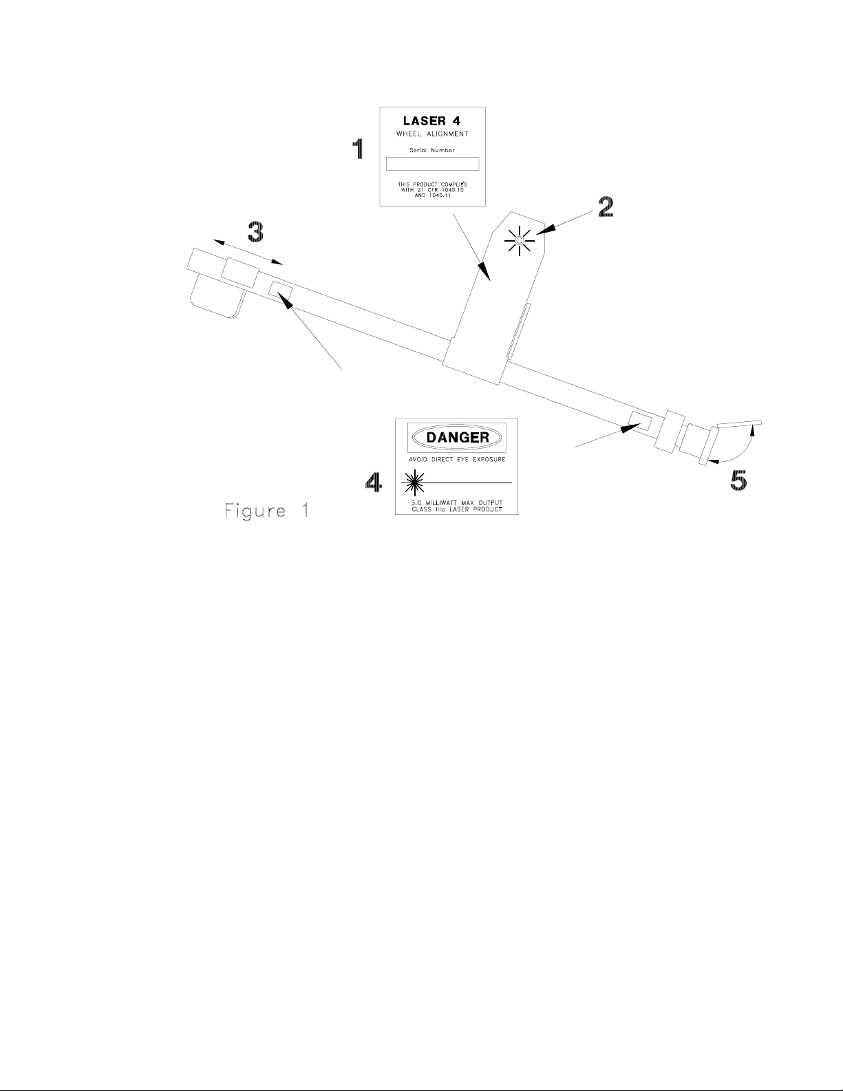
The Laser 4 Plus is a four-wheel alignment system t h a t uses three Class II laser products. These lasers have a
maximum output power of 5.0 milliwatts. The laser tubes meet all government safety standards, although
common sense dictates that one should not stare directly into the beam. Laser precision is unaffected by light,
temperature, and the concentrated light beam is clearly visible anywhere. The following precautions have been
taken to insure the safety of the system (See Fig. 1):
1) Serial Number label is located on underside of casting on power supply cover. Each serial number is
recorded for future identification.
2) LED light comes on as soon as power is activated to laser beam.
3) Slide cover must be slid toward casting to uncover laser beam (LH Toe Gauge only).
4) Caution decals are located on the unit.
5) Flip-open protective cap protects laser unit when not in use.
CAUTION: Use of controls or adjustments or performance of procedures other than those specified herein
may result in hazardous radiation exposure.
Page 2
Page 4
FOUR WHEEL ALIGNMENT
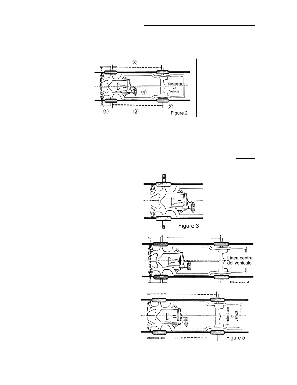
Rear wheels must track and foll ow the front wheels in
a parallel direction with all four wheel adjusted to the
common centerline of the vehicle. (See Fig. 2)
1)Front wheel alignment and
front wheel toe on car
manufacturer’s
specifications.
2)Rear wheel alignment and
rear wheel toe on car
manufacturer’s
specifications.
3)Front wheels track to rear
wheel thrust lines and to
centerline of vehicle.
4)Steering wheel centered in
straight ahead position.
BASIC STEPS TO DO FOUR WHEEL ALIGNMENTS
Step 1
Adjust front wheel camber and caster to car manufacturer’s
settings. (See Fig. 3)
Step 2
Center steering wheel. Adjust front wheel toe to
manufacturer’s setting. (See Fig.4)
Step 3
Adjust f ront wheels to rear wheel in relation to rear axle
position. (See Fig. 5)
Step 4
Adjust rear wheel camber and toe to car manufacturer’s
setting.
Page 3
Page 5
PRE-ALIGNMENT CHECKS
To mai ntain a true alignme nt job; ensure maximum tire mileage a nd steering safety , it is important to p erfor m
certain pre-alignment checks before doing wheel alignment adjustments. They are:
1. Inflate tires to proper inflation pressures.
2. Check car spring height.
3. Check shock absorbers and struts.
4. Inspect steering/suspension parts for wear or looseness. Replace
parts which are worn beyond manufacturer’s accepted tolerances.
5. Check calibrations of the Laser 4 wheel alignment equipment. See
Calibration Procedure section of this manual.
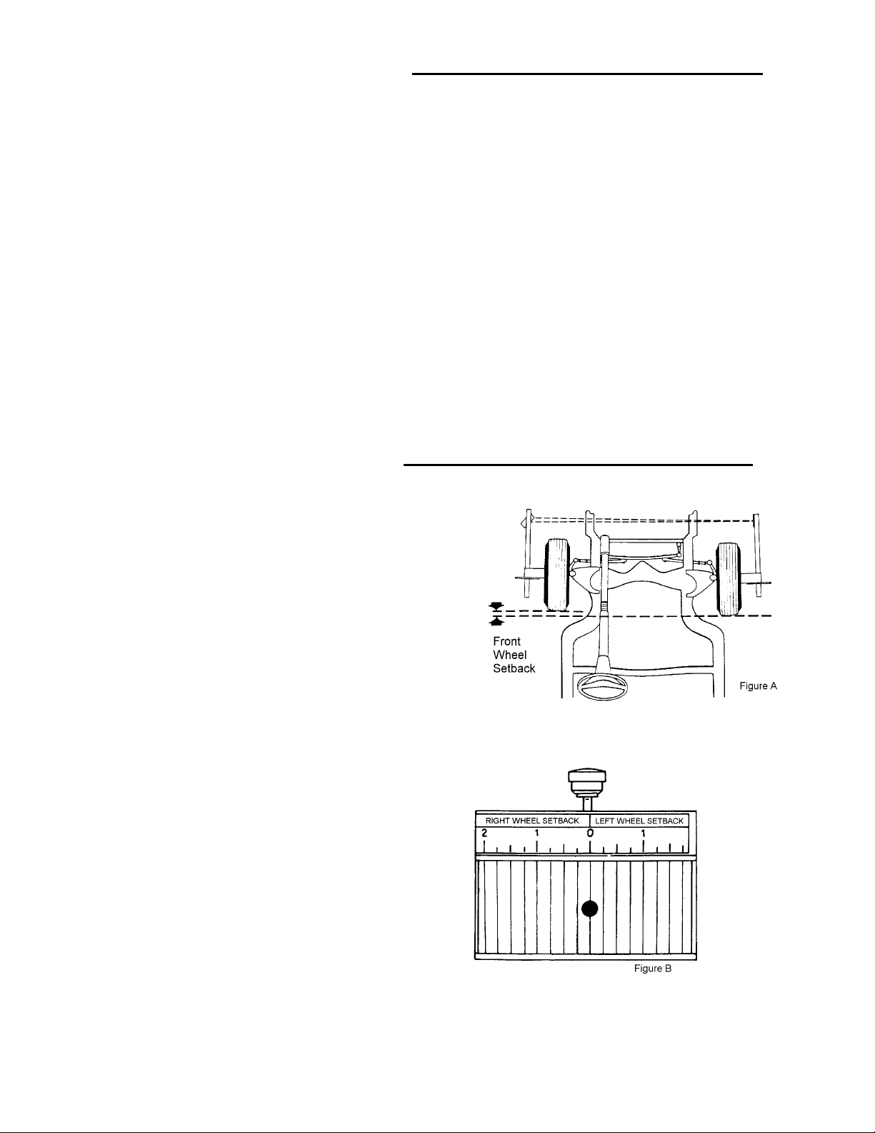
FRONT WHEEL SETBACK
Front wheel setback is a condition in which
one front wheel has been driven or pushed
back, out of alignment, from the opposite
wheel. It is caused by one wheel of the vehicle
striking a curb or pothole in the road forcing
that wheel back from the other (See Fig. A).
To measure front wheel setback with the Laser
4 wheel alignment system, adjust front wheel
toe; center steering wheel, and note the
location of the Laser beam on the wheel
setback scale (See Fig. B) of the passenger side
laser toe gauge. Make sure that the Laser toe
gauges are centered on the wheel clamps. The
scale reads eith er right or left wheel setback.
The front wheel suspension should be adjusted
if the setback is greater than 1/4 inch.
Excessive front wheel setback will cause a
change in caster.
The Laser 4 alignment system automatically
compensates for front wheel setback because
of the use of the tapered, precisely ground
magnets. When toe is adjuste d to zero, the tube
of the optical toe gauges become parallel to
each other. Front wheel toe reading is
unaffected by front wheel setback.
Page 4
Page 6
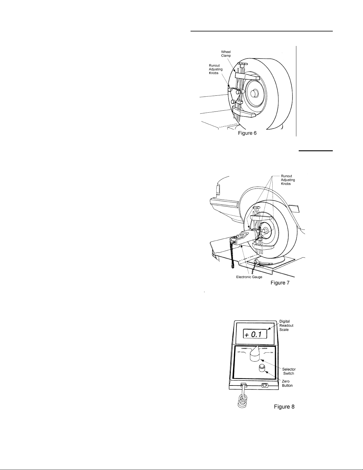
INSTALL WHEEL CLAMPS
Install Wheel Clamps on each wheel. (See Fig. 6) Adjust
the four bars in each clamp for t he best fit to the wheel
rim. Two sets of notches on one end or a threaded pin on
the other end provide for inside or outside mounting to the
wheel rim. Use d ouble-sided foam tape at contact points
on decorative or soft metal rims. Make sure that th e Wheel
Clamps are securely attached.
Select th e configuration which gives the most secure fit
with the least amount of pressure on the wheel rim.
COMPENSATING WHEEL RUNOUT (Laser 4 Plus)
Wheel Clamps must be adjusted to compensate for wheel
runout. This adjustment is made using the three Runout
Adjusting Knobs.
1) Raise wheel and tire from turning gauge or rear wheel
slip plate. Turn wheel so the large wheel clamping
knob is at the top (12 o’clock position).
2) Mount the Electronic Gauge on the Wheel Clamp as
shown (See Fig.7). Center the magnet on the Wheel
Runout Compensating Adapter. Turn the Electronic
Gauge so it is level.
3) Set the selector to CASTER and press the rocker
switch to ON. Press the Zero Button. (See Fig. 8)
4) Rotate the wheel so the wheel clamp adjusting knob
is at the 2 o’clock position. Turn the El ectronic gauge
so it is once ag ain level. Note the value on the Digital
Readout Screen. Ignore the + or - which appears
before the numbers.
Repeat at the 4, 6, 8, and 10 o’clock positions. Relevel the Electronic gauge at each position.
5) Turn the wheel to the position where the largest
numeric reading was observed. Turn the Runout
Adjusting Knobs to decrease this reading by one -half.
Press the Zero Button and repeat step 4, checking for
the largest numeric reading at each of the six
positions.
6) The wheel clamp is properly adjusted when the
Electronic Gauge reads within 0.1 at all six positions.
Page 5
Page 7
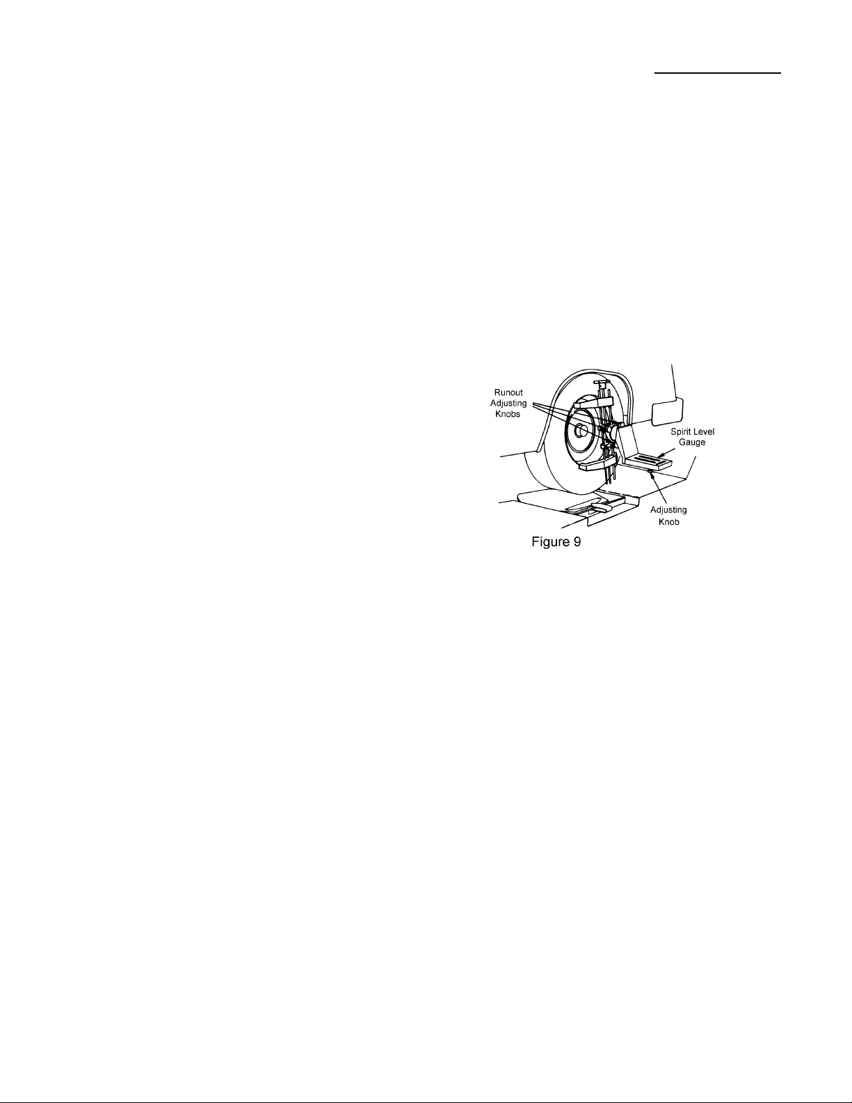
COMPENSATING WHEEL RUNOUT (Laser 4)
Wheel Clamps must be adjusted to compensate for wheel
runout. This adjustment is made using the three Wheel
Runout Adjusting Knobs.
1) Raise wheel and tire from turning gauge or rear wheel
slip plate. Turn wheel so the large wheel clam ping
knob is at the top (12 o’clock position).
2) Mount t he Spirit Level Gauge on the Wheel Clamp.
(See Figure 9) Center the magnet on the Wheel
Runout Compensating Adapter. Turn the Spirit L evel
Gauge so it is level.
3) Zero the Caster Spirit Level using the adjusting knob
on the bottom of the unit.
4) Rotate the wheel so the wheel clamp adjusting knob
is at the 2 o’clock position. Turn the Spirit Level
Gauge so it is once again level. Note the amount of
movement of the bubble away from zero.
Repeat at the 4, 6, 8, and 10 o’clock positions. Relevel the Spirit Level Gauge at each position.
5) Turn the wheel to the position where the largest
movement of the bubble was observed. Turn the
Runout Adjusting Knobs to decrease this reading by
one-half. Zero the Caster Spirit Level and repeat step
4, checking for the largest movement of the bubble
away from zero at each of the six positions.
6) The wheel clamp is properly adjusted when the
bubble does not move away from zero at all six
positions.
Page 6
Page 8

CAMBER READING (Laser 4 Plus)
Camber: The inward or outward tilt of the wheel at the top
Camber is measured in degrees.
Wheel exactly vertical: Zero camber
Top of wheel tilts in: Negative camber
Top of wheel tilts out: Positive camber
A vehicle with Negative Camber is shown in Fig. 10.
Proceed with the following steps to read Camber:
1) Place front wheels in straight ahead position with
steering wheel level. The eng ine must be started if the
vehicle has power steering. Remove locking pins
from the turning radius gauges and rear wheel slip
plates. Rotate each wheel until the large wheel clamp
adjusting knob is at the top.
2) Lower all four wheels until the front wheels rest on
the turning radius gauges and the rear wheels rest on
the rear wheel slip plates. Be sure turning radius
gauges are centered under the front tires.
3) Install brake pedal depressor. The engine must be
running if the vehicle has power brakes.
4) Bounce the vehicle at both front and rear to normalize
the suspension weight.
5) Mount the Electronic Gauge on the left front Wheel
Clamp. Be sure the magnet is centered on the
mounting disk (See Fig. 11).
6) Set the selector to CAMBER and press the switch to
ON (See Fig. 12).
7) Read Camber on the Digital Readout Scale (A
negative 0.3 is indicated in Fig. 12). The numeric read
out will be preceded by a + or - to indica te positive or
negative Camber.
8) Repeat the above procedure on the right front wheel.
If camber adjus tments and specifications are available
for the rear wheels, repeat the above on each wheel.
Page 7
Page 9

Camber Reading (Laser 4)
Proceed with the following steps to read Camber:
1) Place front wheels in straight ahead p osi tion with
steering wheel level. The engine must be started if
the vehicle has power steering. Remove locking
pins from the turning radius g auges and rear wheel
slip plates. Rotate each wheel until the large whee l
clamp adjusting knob is at the top.
2) Lower all f our wheels until the front whe els rest on
the turning radius gauges and the rear wheels rest
on the re ar wheel slip plates. B e sure turning radius
gauges are centered under the front tires.
3) Install brake pedal depressor. The engine must be
running if the vehicle has power brakes.
4) Bounce the vehicle at both front and rear to
normalize the suspension weight.
5) Mount the Spirit Level Gauge on the left front
Wheel Clamp. (See Fig. 13) Be sure the magnet is
centered on the mounting disk.
6) Read Camber at the center of the bubble on the
Camber Scale. The spirit level for Ca mber is loca ted
on the right side of the gauge. (See Fig. 14)
Camber is zero when the center of the bubble is on
zero of the scale.
Camber is positive when the bubble is away from
zero toward the wheel.
Camber is negative when the bubble is away from
zero, away from the wheel.
7) Repeat the above procedure on the right front wheel.
If camber adjustments and specifications are available
for the rear wheels, repeat the above on each wheel.
Page 8
Page 10

CASTER READING (Laser 4 Plus)
Caster: The backward or forward tilt of the ball joint or strut at the top
Caster is measured in degrees:
Spindle support arm straight up and down on the true vertical: Zero Caster
Spindle support arm is tilted forward at the top from true vertical: Negative Caster
Spindle support arm is tilted back at the top from true vertical: Positive Caster
A vehicle with Positive Caster is shown in Fig. 15.
Proceed with the following steps to read Caster:
1) With the Electronic Gauge mounted on the left
front wheel clamp, turn the left front wheel
outward at the front for a 20 degree reading on the
radius gauge. (See Fig. 16)
2) Turn the Electronic Gauge so it is level.
3) Set the selector to CASTER and press the switch to
ON. Press the Zero Button. (See Fig. 18)
4) Turn the wheel inward at t he front for a 20 degree
reading on the radius gauge. (See Fig. 17) This is a
total swing of 40 degrees.
5) Turn the Electronic Gauge so it is level.
6) Read Caster on the Digital Readout Scale (A positiv e
1.0 is indicated in Fig.18). The numeric reading will
be preceded by a + or - to indic ate positive or negative
Caster.
7) Repeat the above procedure on the right front wheel.
Page 9
Page 11

CASTER READING (LASER 4)
Proceed with the following steps to read Caster:
1) With the Spirit Level Gauge mounted on the left front
wheel clamp, turn the left front whe e l o utward at
the front for a 20 degree reading on the radius
gauge. (See Fig. 19)
2) Turn the Spirit Level Gauge so it is level.
3) Adjust the Caster bubble to zero with the adjusting
knob on the bottom of the gauge.
4) Turn the wheel inward at the front for a 20 degree
reading on the radius gauge. This is a total swing
of 40 degrees. (See Fig. 20)
5) Turn the Spirit Level Gauge so it is level.
6) Read Caster at the center of the bubble on the
Caster Scale. The spirit level for Caster is located
on the left side of the gauge. See the figure to the
right. (See Fig. 21)
Caster is zero when the center of the bubble is on zero
of the scale.
Caster is positive when the bubble is away from
zero, away from the wheel.
Caster is negative when the bubble is away from
zero, towards the wheel.
7) Repeat the above procedure on the rig ht front wheel.
Page 10
Page 12

STEERING AXIS INCLINATION
(SAI) READING
(LASER 4 Plus)
SAI: The inward tilt of the ball joint or strut at the top
.
Proceed with the following steps to read SAI:
1) With the Electronic Gauge mounted on the left front
wheel clamp, turn the left front wheel outward at the
front for a 20 degree reading on the radius gauge.
(Refer to Fig.19)
2) Turn the Electronic Gauge so it is level.
3) Set the selector to SAI and press the switch to ON.
Press the Zero Button. (See Fig. 23)
4) Turn the wheel inward at the front for a 20 degree
reading on the radius gauge. This is a total swing of
40 degrees. (See Fig. 20)
5) DO NOT RE-LEVEL THE ELECTRONI C GAUGE.
6) Read SAI on the Digital Readout Scale (A positive
14.5 is indicated Fig. 23)
7) Repeat the above procedure on the right front wheel.
INCLUDED ANGLE
Included Angle: Total of the Camber and SAI Readings
Subtract negative Camber from SAI (as for the above example):
SAI 14.5
Camber -0.3
Included Angle 14.2
Add positive Camber readings to SAI: SAI 14.5
Page 11
Camber +0.5
Included Angle 15.0
Page 13

STEERING AXIS INCLINATION (SAI) READING
(Laser 4)
SAI: The inward tilt of the ball joint or strut at the top
.
Proceed with the following steps to read SAI:
1) With the Spirit Level Gauge mounted on the left front
wheel clamp, turn the left front wheel outward at the
front for a 20 degree reading on the radius gauge. (See
Fig. 24)
2) Pivot the Spirit Le vel Gauge so that the SAI bubble reads
zero on scale “L”. (See Fig 26)
Note: The bottom scale marked “L” is for the left wheel
and the upper scale marked “R” is for the right wheel.
3) Turn the wheel inward at the front for a 20 degree
reading on the radius gauge. This is a total swing of 40
degrees. (See Fig. 25)
4) DO NOT RE-LEVEL THE ELECTRONIC GAUGE.
5) Read center of SAI bubble for SAI readout. (See Fig. 26)
If the SAI reading is higher than the scale on the gauge, turn
the wheel until an 8 degree r eading is reached. Re-adjust the
gauge for a reading of zero and continue turning the wheel.
Add the 8 degrees to the final reading to obtain the actual
SAI reading.
6) Repeat the above procedure on the right front wheel. Use the
scale labeled “R”. (See Fig. 26)
Page 12
Page 14

INSTRUMENTATION SET-UP
Center the Steering Wheel:
Center the steering wheel in the straight ahead position and clamp in place with the Steering Wheel Holder.
The engine must be running to set the steering wheel position on cars with power steering.
Mount the Left & Right Laser Toe Gauges:
1) Determine the manufacturer’s preferred total toe specification for the front wheels. Rotate the tapered
magnet on each Laser Toe Gauge to one-half this specified value. (See Fig. 27)
EXAMPLE: The manufacturer’s preferred total toe specification is 0.08 inches Toe In. Rotate both of
the tapered magnets to one-half this value which is 0.04 inches.
2) Mount the Laser Toe Gauges to the Wheel Clamps. Center the magnet on the Wheel Runout
Compensating Adapter. Connect the safety strap to the Wheel Clamp for extra protection against damage.
(See Fig. 28)
3) Level the Laser Toe Gauges using the spirit level located on the top.
4) Flip the power switch to ON and open the protective covers on the laser beams.
Mount the Rear Retro-screens:
1) Determine the manufacturer’s preferred total toe specification for the rear wheels. Rotate the tapered
magnet on each of the Rear Retro-screens to one-half this specified value. (See Fig. 27)
2) Mount the left and right R ear Retro-screens to the Wheel Clamps. Center the magnet on the Wheel
Runout Compensating Adapter. Connect the safety strap to the Wheel Clamp for extra protection against
damage.
Page 13
Page 15

FRONT WHEEL TOE READING
Toe: The difference in distance between the front and rear of the front wheels
Toe-in: Distance between front of wheels is less than distance between rear of wheels
Toe-out: Distance between front of wheels is greater than distance between rear of wheels
Adjust Laser Beam Mirror & Target:
The Left Laser Toe Gauge projects a laser beam onto the
right mirror (A). This beam is reflected back to the
graduated toe scale on the Left Lase r Toe Gauge.(See Fig.
29)
Adjust the laser beam vertically t o the cente r of the mirror
(A) by using the knob (E) on the Left Laser Toe Gauge.
Rotate the laser beam assembly inside the tube of the L eft
Laser Toe Gauge. Re-tighten knob.
If the laser beam, reflected back from the mirror (A),
doesn’t strike the graduated toe scale, loosen both knobs
(R) on the Right Laser Toe Gauge (See Fig. 30). Rotate the
mirror housing (A) until the laser beam image strikes the
graduated toe scale. Re-tighten both knobs.
Figure 30
Reading Front Wheel Toe:
Read Front Wheel Toe on the graduated toe scale on the
Left Laser Toe Gauge. (See Fig. 31)
Toe is within spec if the laser beam image is in the ce nter
of the scale at zero.
Figure 31
One-half of the manufacture r’s to tal toe specification is already dialed in with each of the magnets, so a
reading of zero on these scales means the toe is correctly adjusted to the manufacturer’s specification.
Page 14
Page 16

TOE READING ILLUSTRATIONS
Page 15
Page 17

FRONT WHEEL ALIGNMENT VEHICLE CENTERLINE
1) Project the laser beams from the Left and Right Toe
Gauges onto the Rear Retro-screens. If the beam does
not strike the rear mirror, check the level of the Laser
Toe Gauge. (See Fig. 32)
2) Note the readings on the scales of the rear screens.
Add both readings and divide by two.
3) Adjust both tie rods or tie rod adjusting sleeves
equally so that the rear screens register the desire d
reading determined in Step 2.
EXAMPLE:
One rear wheel screen registers 5 (See Fig. 33) and
the other one registers 7 (See Fig. 34), the total is 12.
Divide by 2 and adjust both tie rods equally until the
laser beam falls on 6 on each retro screen.
4) Re-check front wheel toe to be sure it remains on
zero. If not, re-adjust front wheel toe to zero. Recheck the rear retro-screens for equal readings.
This is a “Two Wheel Alignment”
Page 16
Page 18

THRUST ANGLE ALIGNMENT
1) Check that both Laser Toe Gauges are level. The laser beams should be visible on the rear Retro-screen
mirrors (See Fig. 35).
2) Rotate the rear Retro-screen a ssemblies out of level, if necessary , so that the laser beams will be refle cted
back to the front Toe Gauges and be visible on the Thrust Angle Scales.
3) Note the readings on the Thrust Angle Scales. Add both readings and divide by two.
4) Adjust both tie rods or tie rod adjusting sleeves equally so that the Thrust Angle Scales register the
desired reading determined in Step 3.
EXAMPLE:
One Thrust Angle Scale registers 4 (See Fig. 36)and the other one registers 6 (See Fig. 37), the total is
10.
Divide by 2 and adjust both tie rods equally until the laser beam falls on 5 on each Thr u st Ang le Scale.
(See Fig. 39 and Fig. 40)
This is a Thrust Angle Alignment where the front wheel position is corrected for rear wheel misalignment.
Page 17
Page 19

Total Vehicle Four-Wheel Alignment
1) Check that both Laser Toe Gauges are level. The laser beams should be visible on the rear Retro-screen
mirrors.(See Fig. 38)
2) Rotate th e rea r Ret ro-scree n assemblies out of level if necessa ry, so that the la ser beams will be reflected
back to the front Toe Gauges and be visible on the Thrust Angle Scales.
3) Note the reading on each of the Thrust Angle Scales. Adjust the toe of each rear wheel until the laser
beam image on the corresponding Thrust Angle Scale is in the middle at the number 5. (See Fig. 39 and
Fig. 40)
This completes a four-wheel alignment.
Page 18
Page 20

CALIBRATION PROCEDURE
Mount and level the Calibration Bar on Calibration Stands or the rear of the Storage Cart
Calibration of Front Wheel Toe Laser Beam (See Figure 42)
1) Rotate the tapered magnets on the Left and Right T oe
Gauges to zero.
2) Mount the Left and Right Toe Gauge s o n t h e ends of
the Calibration Bar. Be sure the centers of the
magnets fit over the raised machined surfaces at the
ends of the Calibration bar. (See Fig. 41)
3) Level both Toe Gauges and check the laser beam on the mirror screen (A). If the laser beam image is not
located midway up on the mirror screen (A), loosen the knob (E) on the Left Toe Gaug e and slide it up
or down. This moves the laser beam image vertically until it is on the mirror.
4) The center of the laser beam image should be on zero on the screen (A). If not, alternately adjust Allen
set screws of the laser diode bulb reta iner on the Left Toe Gaug e until the center of the beam image reads
zero on the Right Toe Gauge screen (A).
There are four Allen set scre ws on the laser diode retainer. The top and b ottom set screws (D) control the
vertical movement of the beam image. The left and right screws (B) control side-to-side movement of
the beam image.
5) Adjust the mirror (A) up or down as required so the reflected laser beam image is on the fron t toe sc al e.
Loosen knobs (R) to make any required adjustments.
6) Adjust Allen set screw s (F ) un til the center of the la ser beam image r eads zero on the front toe scale (C).
Page 19
Page 21

CALIBRATION PROCEDURE
The Gauges are now parallel - “Toe reads zero”
Calibration of Right & Left Toe Gauge Laser Beams
1) Rotate all tapered magnets on the Toe Gauges and
Rear Retro-screens to zero
2) Mount the Left Toe Gauge and Left Retro-screen to
the machined surfaces on the side of the C alibrati on
Bar. (See Fig. 43)
Page 20
Page 22

CALIBRATION PROCEDURE
Calibration of Right & Left Toe Gauge Laser Beams (continued)
3) Level the Toe Gauge and project the laser beam
image on the rear Retro-screen. (See Figure 44) The
center of the beam image must be on 6 and midway
up the mirror. If not, alternately loosen and tighten
Allen set screws on the laser diode retainer.
There are four Allen set screws on the laser diode
retainer. (See Figure 45) The top and bottom set
screws (D) control the vertical movement of the beam
image. The left and right screws (B) control si de-toside movement of the beam image.
4) Check the location of the reflected laser beam image
on the Thrust Angle Scale on the Laser Toe gauge.
With the Rear-retro Screen level, the center of the
image should be mid-way up and on 5 on the Thrust
Angle Scale.
If not, adjust the two screws (M) (See Fig. 44) until
the image is on 5 and adjust screw (L) until the im age
is mid-way up on the Thrust Angle Scale.
5) Remove the Left Toe Gauge and Left Retro-screen.
Mount the Right Toe Gauge and Right Retro-screen
and repeat steps 1 through 4.
The Retro-screen is now at a perfect 90 degree angle to the front Toe Gauge and the laser beam image
indicates zero toe on the Thrust Angle Screen.
Page 21
Page 23

BATTERY REPLACEMENT
The Laser 4 is powered by eight “C” batteries; four batteries located in each Toe Gauge. Alkaline batteries
are recommended for extended life.
The batteries should be replaced when the laser beam image becomes dim or can no longer be seen.
To replace the batteries (See Figure 46):
1) Flip the Laser Toe Gauge switch to OFF.
2) Place the Laser Toe Gauge on a workbench with the underside of the casting facing up.
3) Loosen the battery cover locking knobs and open the cover.
4) Replace the batteries foll owing the di agram in th e battery holder. Flip the switch t o ON t o be s u r e t h e
laser diode operates. Flip the switch to OFF.
5) Close the cover and secure with the battery cover locking knobs.
Page 22
 Loading...