

Page 1

OPERATION MANUAL
ESX-2
Fuel System Cleaner
RTI Technologies, Inc
4075 East Market St.
York, PA 17402
800-468-2321
www.rtitech.com
Manual P/N 035-80873-00 (Rev A)
Page 2

Table of Contents
Component Description ............................2
Safety Precautions................................3
Keypad Functions ................................4
Fuel System Identification ..........................6
Port Fuel Injection (PFI) Setup.......................7
Port Fuel Injection (PFI) Cleaning Procedure ........... 10
Throttle Body Injection (TBI) Setup .................. 11
Throttle Body Injection (TBI) Cleaning Procedure ....... 14
Continuous Injection System (CIS) Setup ............. 15
Continuous Injection System (CIS) Cleaning Procedure . . 18
Carburetor System Setup.......................... 19
Carburetor System Cleaning Procedure ............... 22
Vehicle Diagnostic ............................... 23
Intake System Cleaning ........................... 26
Maintenance ................................... 27
Parts Identification ............................... 28
Flow & Wiring Diagram............................ 29
BEFORE FIRST TIME USE
Pour one-half bottle (4 ounces) of the RTI FUEL SYSTEM CLEANER
into the Fill Port.
Then pour gasoline into the Fill Port until the level is at the EMPTY
mark in the Fuel Level Window.
This will ensure precise concentration of fuel to cleaner.
Page 1
Page 3
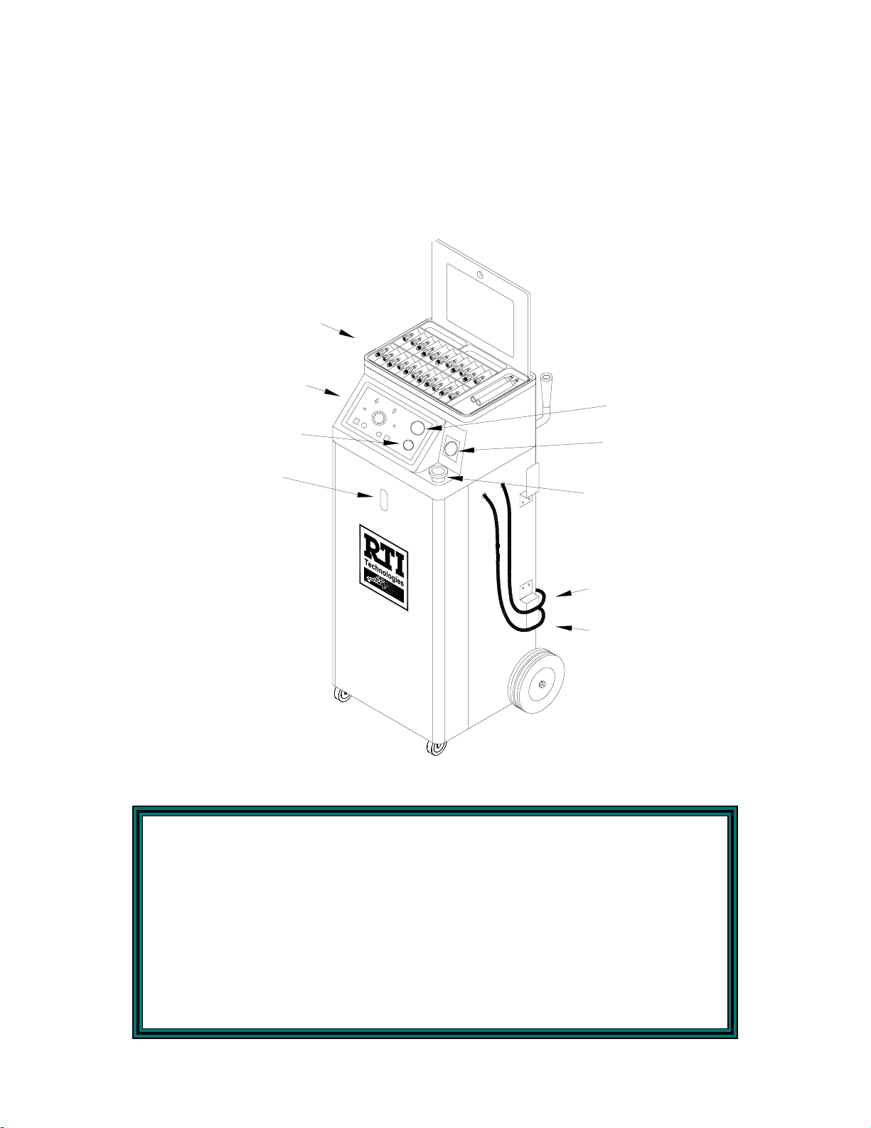
Component Descriptions
Unpack all components. Use laminated placard to verify fitting adapter quant ities. Items not shown
are one RTI filter as well as 1 case (twel ve bottles) of RTI FUEL SYSTEM CLEANER. Unpack RTI
FUEL SYSTEM CLEANER and RTI filter. Store contents in the rear storage compartments of the
ESX. (see Page 28)
Contact RTI if any items are missing or damaged.
FITTING ADAPTER SET
KEYPAD
PRESSURE
CONTROL REGULATOR
FUEL LEVEL
WINDOW
FUEL
PRESSURE GAUGE
VACUUM GAUGE
FILL PORT
10 FT RED HOSE
10 FT BLACK HOSE
BEFORE FIRST TIME USE
Pour one-half bottle (4 ounces) of the RTI FUEL SYSTEM CLEANER
into the Fill Port.
Then pour gasoline into the Fill Port until the level is at the EMPTY
mark in the Fuel Level Window.
This will ensure precise concentration of fuel to cleaner.
Page 2
Page 4

Safety Precautions
WARNING: Failure to follow these precautions can result in serious
injury or death.
• Read and understand the Operation Manual completely before operating this unit.
• Always wear proper eye and skin pr otection when operating and maintaini ng this equipment.
• Take precautions to keep clothing, hair, hands, hoses, etc. away from all moving parts of the
vehicle.
• Fuel systems can be under high pressure, even after the engine has been turned of f, and
engine parts can be extremely hot. Always use extreme caution when connecting and
disconnecting hoses and adapters.
• Always keep a fire extinguishing device nearby when working with flammable liquids.
• NOTE: Vehicle exhaust contains Carbon Monoxide, which is lethal and odorless.
Choose a well ventilated work area and avoid inhaling any fumes when operating the
equipment.
• Check engine oil and coolant level. Refill if low. Do not perform the cleaning if either is low.
• Flush solutions are combustible and are harmful if swallowed. If swallowed call a doctor
immediately and do not induce vomiting. If Flush Solution gets in the eyes flush with water
immediately. For contact with skin wash with soap and water. Apply skin lotion if necessary
to sooth irritation.
• Immediately clean up any gasoline or chemical spills and use a proper container for disposal.
• Comply with local, state, and federal regulations for fluid disposal.
• Material Safety Data Sheets (MSDS) must be obtained on all chemicals and placed in a shop
file for reference.
BEFORE FIRST TIME USE
Pour one-half bottle (4 ounces) of the RTI FUEL SYSTEM CLEANER
into the Fill Port.
Then pour gasoline into the Fill Port until the level is at the EMPTY
mark in the Fuel Level Window.
This will ensure precise concentration of fuel to cleaner.
Page 3
Page 5
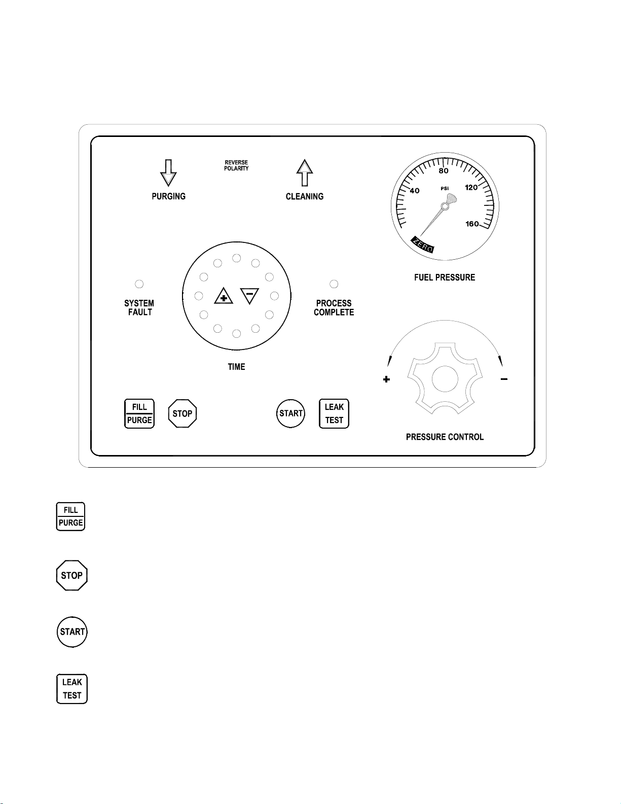
Keypad Functions
The ESX is an automatic fuel system cleaning machine that has state-of-the-art controls.
Operation of this machine is intuitive and easy to master . Below is a list of the keypad functions.
60
55
50
5
10
45
40
35
30
15
20
25
Fills tank inside the ESX unit from th e vehicle fuel system. Also used to purge or
relieve the pressure in the pressure line in the fuel system before disconnecting.
Stops any procedure the moment it is pushed. Also acknowledges the completion
of a process and is used to stop the buzzer.
Held to set pressure for the cleaning processes which in turn begins the cleaning
procedure, also can be used to empty the system contents.
Holds pressure in the li nes w hile the timer counts dow n a default or adj usted time.
The default time is 5 minutes.
Page 4
Page 6
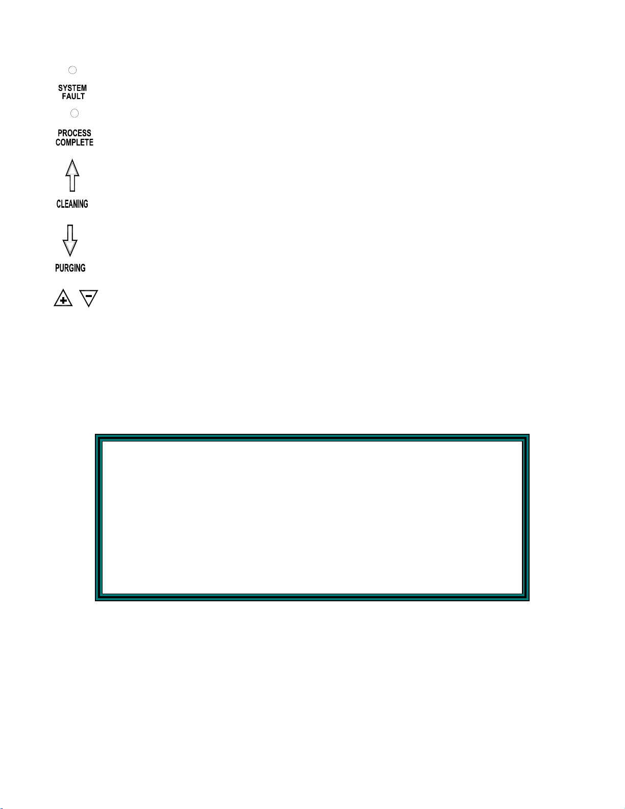
Keypad Functions
Illuminates whenever there is an error with the selected procedure.
Illuminates when the selected process is complete. The buzzer will sound
continuously when this is illuminated.
Illuminates when the ESX is pumping out of the red line. Examples of this are the
cleaning procedure and when emptying the internal tank.
Illuminates when the ESX is pulling from the red line. E xamples of this are the
purging procedure and when filling from the vehicle fuel system.
Increases and decreases by 5 minute i ntervals the remaining time on the LED timer.
BEFORE FIRST TIME USE
Pour one-half bottle (4 ounces) of the RTI FUEL SYSTEM CLEANER
into the Fill Port.
Then pour gasoline into the Fill Port until the level is at the EMPTY
mark in the Fuel Level Window.
This will ensure precise concentration of fuel to cleaner.
Page 5
Page 7
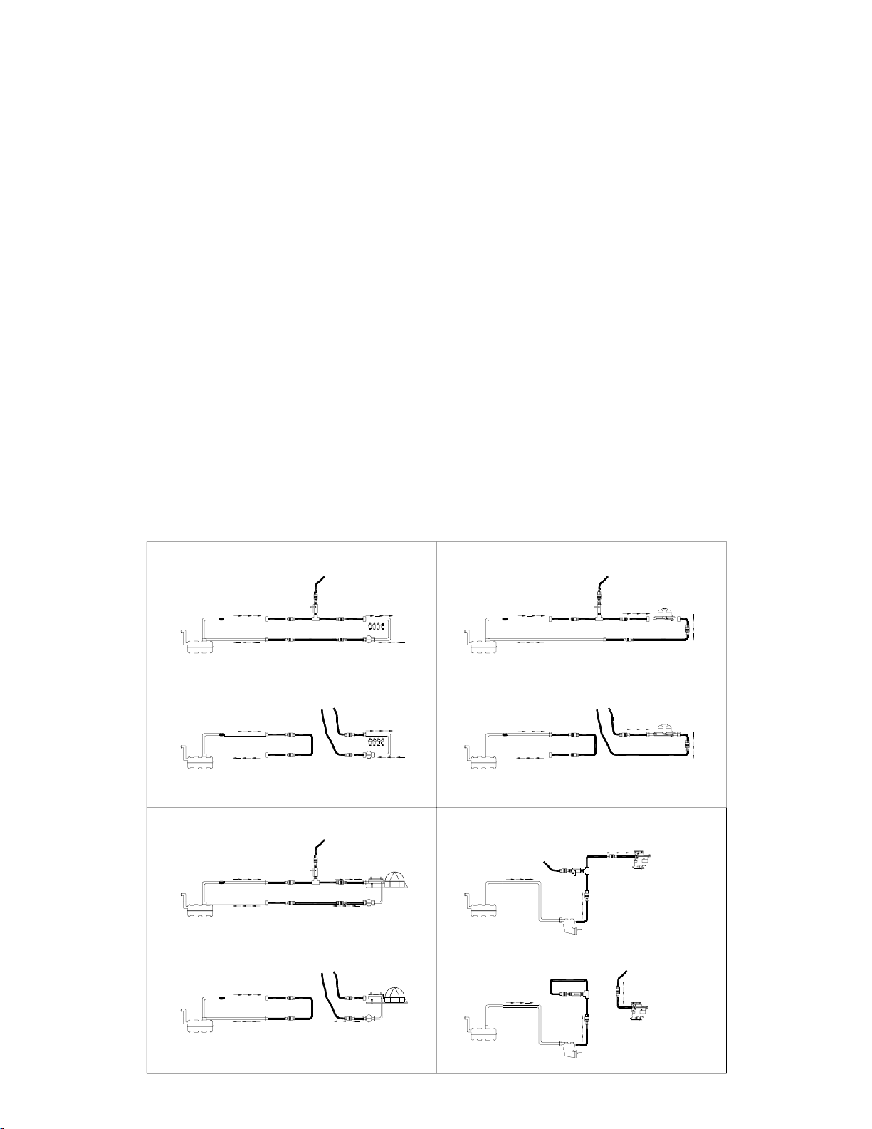
Fuel System Identification
The Fuel System type must be determined before proceeding with any cleaning or diagnostic
procedures. The following four systems are the only types that can be serviced w ith the RTI ESX
unit.
Port Fuel Injection (PFI)- This system uses a single electronic injector per cylinder,
mounted such that fuel spray is directed into the intake port. (See Page 7)
Throttle Body Injection (TBI) - Centrally mounted, like the carburetor system, but utiliz es
one or two electronic injectors. (See Page 11)
Continuous Injection System (CIS) - Look for the fuel distributor with solid steel or flex
steel lines running from the fuel distributor to each individual i njector . The fuel distributor
controls the amount of fuel sprayed into the intake port while the injector controls opening
and closing pressure. (See Page 15)
Carburetor System - Sizes and shapes vary, but these systems are easily identified by
locating the choke plate underneath the air filter housing. (See Page 19)
PORT FUEL INJECTION FIG. A
ESX RED HOSE
PRESSURE LINE
VEHICLE FUEL TANK
FILTER
RETURN LINE
ADAPTER
ADAPTER
TEE ADAPTER
LOOP ADAPTER
ADAPTER
ADAPTER
PRESSURE LINE
FUEL RAIL
FUEL
PRESSURE
REGULATOR
RETURN LINE
PORT FUEL INJECTION FIG. B
ESX RED HOSE
PRESSURE LINE
LOOP
ADAPTER
ADAPTER
FUEL RAIL
FUEL
PRESSURE
REGULATOR
RETURN LINE
VEHICLE FUEL TANK
FILTER
PRESSURE LINE
RETURN LINE
ADAPTER
ADAPTER
ESX BLACK HOSE
ADAPTER
CONTINUOUS INJECTION SYSTEM FIG.A
ESX RED HOSE
ADAPTER
ADAPTER
FUEL
PRESSURE
REGULATOR
FUEL DISTRIBUTOR
VEHICLE FUEL TANK
PRESSURE LINEFILTER
RETURN LINE
ADAPTER
ADAPTER
TEE ADAPTER
LOOP ADAPTER
PRESSURE LINE
RETURN LINE
CONTINUOUS INJECTION SYSTEM FIG.B
ESX RED HOSE
ADAPTER
LOOP
RETURN LINE
ADAPTER
FUEL
PRESSURE
REGULATOR
FUEL DISTRIBUTOR
VEHICLE FUEL TANK
FILTER PRESSURE LINE
RETURN LINE
ADAPTER
ADAPTER
ESX BLACK HOSE
ADAPTER
THROTTLE BODY FIG. A
FILTER
PRESSURE LI NE
VEHICLE FUEL TANK
RETURN LINE
THROTTLE BODY FIG. B
PRESSURE LINE
FILTER
VEHICLE FUEL TANK
RETURN LINE
CARBURETOR FIG. A
ESX RED HOSE
SUPPLY LINE
VEHICLE FUEL TANK
CARBURETOR FIG. B
SUPPLY LINE
VEHICLE FUEL TANK
ADAPTER
ESX BLACK HOSE
ADAPTER
ADAPTER
COMING FROM
FUEL PUMP
FUEL PUMP
LOOP ADAPTER
COMING FROM
FUEL PUMP
FUEL PUMP
LOOP
ADAPTER
TEE ADAPTER
TEE
ADAPTER
ADAPTER
ESX RED HOSE
ADAPTER
ESX RED HOSE
ADAPTER
ESX RED HOSE
GOING INTO
THE CARBURETOR
PRESSURE LINE
ADAPTER
PRESSURE LINE
ADAPTER
CARBURETOR
GOING INTO
THE CARBUR ETOR
CARBURETOR
THROTTLE BODY UNIT
ADAPTER
LOOP ADAPTER
THROTTLE BODY UNIT
ADAPTER
RETURN LINE
RETURN LINE
Page 6
Page 8
Port Fuel Injection (PFI) Setup
The following steps will prepare the ESX for the cleaning procedure. Make sure the vehicle fuel
gauge reads at least 1/8th of a tank before continuing.
Note: Do not proceed with this setup or any cleaning procedure if the engine oil or coolant
level is low. If necessary add appropriate amount of coolant and/or oil to the engine.
Note: If Intake System Cleaning is desired refer to page 26 for proper instructions.
1. Start the vehicle and allow engine to reach normal operating temperature. Turn vehicle
OFF when the proper temperature is reached.
2. Turn Pressure Control regulator counterclockwise until it is completely open.
3. Connect red (positiv e) cl amp on power cable to red ( positi ve) terminal on v ehicl e battery .
Connect the black (negative) clamp to a ground on vehicle frame as far from the battery
as possible. A ll LED’s on keypad should illuminate for one second and buzzer should
pulse. If not, check connections and make sure REVERSE POLARITY LED is not
illuminated. If REVERSE POLARITY LED is illuminated reverse the battery connections.
4. Remove vehicle gas cap to relieve fuel tank pressure.
5. With the engine no longer running, disconnect the vehicle fuel lines from the fuel rail. There
are now four open ends to connect to: the Pre s s u r e L i n e from the fuel ta nk, the other
Pressure Line going to the rail, the Return Line from the fuel rail, and the other Return
Line to the fuel tank.
6. Connect the proper adapters to the above listed connection points as shown in the
following illustration.
ESX RED HOSE
FILTER
PRESSURE LINE
ADAPTER
ADAPTER
TEE ADAPTER
LOOP ADAPTER
ADAPTER
ADAPTER
PRESSURE LINE
FUEL RAIL
VEHICLE FUEL TANK
RETURN LINE
FUEL
PRESSURE
REGULATOR
RETURN LINE
Page 7
Page 9

Port Fuel Injection (PFI) Setup
7. Attach the Tee adapter to both pressure line adapters, the valve should be in the closed
position. Then connect the ESX Red H ose to the valve on the Tee adapter as shown in the
previous illustration.
8. Attach Loop adapter to both return side adapters as shown in the previous illustration. Note
that the ESX Black Hose is not used at this time.
9. Start the vehicle, turn the Tee adapter valv e counterclockwise to open it. C heck for leaks.
Watch the Fuel Pressure gauge on the ESX control panel. A drop in pressure could
indicate a leak.
CAUTION - CAUTION - CAUTION
-DIAGNOSTICS-
The fuel system is now ready to perform diagnostic tests. The Leakdown Test has to be
performed prior to the pre-cleaning procedure to eliminate the possibility of a leaky
injector. If an injector is leaking and the operator continues without testing, a cylinder
may fill with gasoline and cause serious engine damage or possible engine failure. For
instructions on how to perform all of the diagnostic tests, refer to the Vehicle
Diagnostic section (see Page 23 ). Once completed, continue with Step 10 below.
10. Press and hold the Fill/Purge button on the Keypad until the Fuel Level window
indicates an increase of 1/4 in the ESX fuel tank. If the vehicle stalls, turn the valve on
the Tee adapter 1/8 turn clockwise. Restart the vehicle and slowly open the valve, by
turning counterclockwise, until the engine starts to stutter. Ease the valve back until the
engine smooths and continue filling. If the vehicle repeatedly stalls repeat this step until
ESX fuel tank is 1/4 full.
11. Turn OFF the vehicle.
12. Add 8 oz. of RTI FUEL SYST EM CLEANER, through the ESX fill port for e very 1/4
added to the ESX fuel tank.
13. Press and hold the Fill/Purge button for five seconds to relieve the pressure in the ESX
Red Hose.
CAUTION: Flammable liquid can squirt out of pressurized fuel lines when connecting
or disconnecting. Always wear eye protection. Obtain zero pressure before
connecting or disconnecting any fuel lines or adapters. Always wear
chemical resistant gloves when connecting or disconnecting fuel lines.
Wrap a shop rag around the pressure point when connecting or
disconnecting. Avoid exposure to flames, sparks, hot engine parts, and/or
ignition sources. By not following the above cautionary steps the operator
will be subjecting himself to serious injury or possible death.
Page 8
Page 10

Port Fuel Injection (PFI) Setup
14. Carefully disconnect the Loop adapter from the return lines. Close the valve on the Tee
adapter and carefully disconnect the Tee adapter from the ESX Red Hose and the
pressure lines.
15. Connect one end of the Loop adapter to the pressure line coming from the vehicle fuel
tank. Connect the other end of the loop adapter to the return line going back to the fuel
tank. This forms a loop making it unnecessary to disconnect the fuel pump. This
connection is illustrated below.
ESX BLACK HOSE
FILTER PRESSURE LINE
ADAPTER
LOOP
ADAPTER
ADAPTER
RETURN LINE
VEHICLE FUEL TANK
ESX RED HOSE
ADAPTER
ADAPTER
PRESSURE
REGULATOR
PRESSURE LINE
FUEL RAIL
FUEL
RETURN LINE
16. Connect the ESX Red Hose to the pressur e line g oing i nto the fuel rail. C onnect the ESX
Black Hose to the return line coming from the fuel rail. These connections are shown in the
illustration above.
Page 9
Page 11

Port Fuel Injection (PFI) Cleaning Procedure
The following steps will circulate the cleaning mixture through the Port Fuel Injection System,
cleaning the fuel rail, injector screens and pressure regulator.
1. Verify that the Port Fuel Injection Setup section is complete.
2. Press and hold the Start button.
3. Turn the ESX Pressure Control regulator clockwise until the Fuel Pressure Gauge displays
at least 4 psi or the Cleaning Arrow LED stays illuminated. This will clean the PFI unit,
injector screens, fuel rail, and pressure regulator and filter any contaminants through the
ESX filtering system.
4. Release the Start button and continue to turn ESX Pressure Control regulator clockwise
until it is completely closed. Make a note of the Fuel Pressure gauge reading. This is the
true operating pressure of the vehicle pressure regulator without vacuum assist when the
engine is running at normal operating temperature.
5. Press the + button to increase or the - button to decrease the time on the ESX LED timer
display until the 10 minu te LED is illuminated.
Caution: If a Leakdown test has not been performed, do not proceed with the following
steps. Refer to the Setup procedure for the correct instructions.
6. After time has expired on the rail cleaning process press the START button until the
pressure rises again.
7. Press the + button to increase or the - button to decrease the time on the ESX LED timer
display until the 30 minute LED is illuminated. Run time may be adjusted depending on the
condition of the vehicle fuel system.
8. Start the vehicle to begin the engine cleaning procedure. At this time if the vehicle is
equipped with a cold start injector you may use an injector pulser to energize the cold start
injector a few times to clean it.
9. When the time expires, the unit will automatically shut off and purge itself for five seconds.
This will shut off the engine and illuminate the PROCESS COMPLETE LED as well as
sound the buzzer. Turn the vehicle ignition OFF.
10. Turn the Pressure Control regulator counterclockwise to open it and press and hold the
FILL/PURGE button for five seconds to relieve pressure in the ESX Red Hose.
11. Disconnect loop adapter and use a shop rag at all connection points before disconnecting.
12. Disconnect the battery leads, hoses, and adapters. Reconnect all of the vehicle fuel lines.
Reinstall the vehicle fuel cap.
13. Start the vehicle and verify that there are no leaks in the fuel system.
14. Always test drive the vehicle for three miles or run at 3000 rpm for two to three minutes to
flush all RTI FUEL SYSTEM CLEANER out of the vehicle fuel and exhaust system.
Page 10
Page 12

Throttle Body Injection (TBI) Setup
The following steps will prepare the ESX for the cleaning procedure. Make sure the vehicle fuel gauge
reads at least 1/8th of a tank before continuing.
Note: Do not proceed with this setup or any cleaning procedure if the engine oil or coolant
level is low. If necessary add appropriate amount of coolant and/or oil to the engine.
Note: If Intake System Cleaning is desired refer to page 26 for proper instructions.
1. Start the vehicle and allow engine to reach normal operating temperature. Turn vehi cle OFF
when the proper temperature is reached.
2. Turn Pressure Control regulator counterclockwise until it is completely open.
3. Connect red (positive) clamp on power cable to red (positive) terminal on vehicle battery.
Connect the black (negative) clamp to a ground on vehicle frame as far from the battery as
possible. All LED’s on keypad should illuminate for one second and buzzer should pulse. If
not, check connections and make sure REVERSE POLARITY LED is not illuminated. If
REVERSE POLARITY LED is illuminated reverse the battery connections.
4. Remove vehicle gas cap to relieve fuel tank pressure.
5. With the engine no longer running disconnect the vehicle fuel lines from the fuel rail. There ar e
now four open ends to connect to: the Pressure Line from the fuel t ank, the other Pressure
Line going to the throttle body, the Return Line from the throttle body, and the other
Return Line to the fuel tank.
6. Connect the proper adapters to the above listed connection poi nts as shown in the following
illustration.
ESX RED HOSE
THROTTLE BODY UNIT
FILTER
PRESSURE LINE
ADAPTER
TEE ADAPTER
ADAPTER
PRESSURE LI N E
ADAPTER
LOOP ADAPTER
RETURN LINE
ADAPTER
VEHICLE FUEL TANK
RETURN LINE
Page 11
Page 13

Throttle Body Injection (TBI) Setup
7. Attach the Te e adapter to both pressure line adapters, the valve should be in the closed
position . Then connect the ESX Red Hose to the valve on the Tee adapter as shown in the
previous illustration.
8. Attach Loop adapter to both return side adapters as shown in the previous illustration. Note
that the ESX Black Hose is not used at this time.
9. Start the vehicle, turn the Te e adapter valve counterclockwise to open it. Check for leaks.
Watch the Fuel Pressure gauge on the ESX control panel. A drop in pressure could indi cate
a leak.
CAUTION - CAUTION - CAUTION
-DIAGNOSTICS-
The fuel system is now ready to perform diagnostic tests. The Leakdown Test has to be
performed prior to the pre-cleaning procedure to eliminate the possibility of a leaky
injector. If an injector is leaking and the operator continues without testing, a cylinder may
fill with gasoline and cause serious engine damage or possible engine failure. For
instructions on how to perform all of the diagnostic tests, refer to the Vehicle Diagnostic
section (see Page 23 ). Once completed, continue with Step 10 below.
10. Press and hold the Fill/Purge button on the Keypad until the Fuel Level window i ndicates an
increase of 1/4 in the ESX fuel tank. If the vehicle stalls, turn the val ve on the Tee adapter 1/8
turn clockwise. Restart the vehicle and slowly open the valve, by turning counterclockwise,
until the engine starts to stutter. Ease the valve back until the engine smooths and continue
filling. If the vehicle repeatedly stalls repeat this step until ESX fuel tank is 1/4 full.
11. Turn OFF the vehicle.
12. Add 8 oz. of RTI FUEL SYSTEM CLEANER, through the ESX fill port for every 1/4 added to
the ESX fuel tank.
13. Press and hold the Fill/Purge button for five seconds to relieve the pressure in the ESX R ed
Hose.
CAUTION: Flammable liquid can squirt out of pressurized fuel lines when connecting or
disconnecting. Always wear eye protection. Obtain zero pressure before
connecting or disconnecting any fuel lines or adapters. Always wear chemical
resistant gloves when connecting or disconnecting fuel lines. Wrap a shop rag
around the press ure point w hen connecting or disconnecting. Avoid exposure
to flames, sparks, hot engine parts, and/or ignition sources. By not following the
above cautionary steps t he operator will be subjecting himself to serious injury
or possible death.
Page 12
Page 14

Throttle Body Injection (TBI) Setup
14. Carefully disconnect the Loop adapter from the return lines. Close the valve on the Tee
adapter and carefully disconnect the Tee adapter from the ESX R ed Hose and the pressure
lines.
15. Connect one end of the Loop adapter to the pressure line coming from the vehicle fuel tank.
Connect the other end of the loop adapter to the return line going back to the fuel tank. This
forms a loop making it unnecessary to disconnect the fuel pump. This connection is illustrated
below.
ESX RED HOSE
PRESSURE LINE
ADAPTER
THROTTLE BODY UNIT
RETURN LINE
ADAPTER
VEHICLE FUEL TANK
FILTER
ESX BLACK HOSE
PRESSURE LINE
ADAPTER
LOOP
ADAPTER
ADAPTER
RETURN LINE
16. Connect the ESX Red Hos e to the pressure line going into the TBI unit. Connect the ESX
Black Hose to the return line coming from the TBI unit. These connections are shown in the
illustration above.
Page 13
Page 15

Throttle Body Injection (TBI) Cleaning Procedure
The following steps will circulate the cleaning mixture through the Throttle Body Injection System
cleaning the throttle body, injector screens and pressure regulator.
1. Verify that the Throttle Body Injection Setup section is complete.
2. Press and hold the Start button.
3. Turn the ESX Pressure Control regulator cl ockwise until the Fuel Pressure Gauge displays at
least 4 psi or the Cleaning Arrow LED stays illuminated. This will clean the TBI unit, injector
screens, throttle body, and pressure regulator and filter any contaminants through the ESX
filtering system.
4. Release the Start button and continue to turn ESX Pressure Contr ol regulator clockw ise until
it is completely closed. Make a note of the Fuel Pressure gauge reading. This is the true
operating pressure of the vehicle pressur e regulator w ithout vacuum assist when the engine
is running at normal operating temperature.
Caution: If a Leakdown test has not been performed, do not proceed with the following
steps. Refer to the Setup procedure for the correct instructions.
5. Press the + button to increase or the - button to decrease the time on the ESX LED timer
display until the 10 minu te LED is illuminated.
6. After time has expired on the rail cleaning process press the START button until the pressure
rises again.
7. Press the + button to increase or the - button to decrease the time on the ESX LED timer
display until the 30 minute LED is illuminated. Run time may be adjusted depending on the
condition of the vehicle fuel system.
8. Start the vehicle to begin the engine cleaning procedure.
9. When the time expires, the unit will automatically shut off and purge itself for five seconds.
This will shut off the engine and illuminated the PROCESS COMPLETE LED as well as sound
the buzzer. Turn the vehicle ignition OFF.
10. Turn the Pressure Control regulator counterclockwise to open it and press and hold the
FILL/PURGE button for five seconds to relieve pressure in the ESX Red Hose.
11. Disconnect loop adapter and use a shop rag at all connection points before disconnecting.
12. Disconnect the battery leads, hoses, and adapters. Reconnect all of the vehicle fuel lines.
Reinstall the vehicle fuel cap.
13. Start the vehicle and verify that there are no leaks in the fuel system.
14. Always test driv e the vehicle for three miles or run at 3000 rpm for two to three minutes to flush
all RTI FUEL SYSTEM CLEANER out of the vehicle fuel and exhaust system.
Page 14
Page 16

Continuous Injection System (CIS) Setup
The following steps will prepare the ESX for the cleaning procedure. Make sure the vehicle fuel
gauge reads at least an 1/8 of a tank before continuing.
Note: Do not proceed with this setup or any cleaning procedure if the engine oil or coolant
level is low. If necessary add appropriate amount of coolant and/or oil to the engine.
Note: If Intake System Cleaning is desired refer to page 26 for proper instructions.
1. Start the vehicle and allow engine to reach normal operating temperature. Turn vehicle
OFF when the proper temperature is reached.
2. Turn the Pressure Control regulator counterclockwise until it is completely open.
3. Connect red (positiv e) cl amp on power cable to red ( positi ve) terminal on v ehicl e battery .
Connect the black (negative) clamp to a ground on vehicle frame as far from the battery
as possible. A ll LED’s on keypad should illuminate for one second and buzzer should
pulse. If not, check connections and make sure REVERSE POLARITY LED is not
illuminated. If REVERSE POLARITY LED is illuminated reverse the battery connections.
4. Remove vehicle gas cap to relieve fuel tank pressure.
5. With the engine no longer running, disconnect the vehicle fuel lines from the fuel rail. There
are now four open ends to connect to; the Pre s s u r e L i n e from the fuel ta nk, the other
Pressure Line going to fuel distributor, the Return Line from the fuel distributor, and
the other Return Line to the fuel tank.
6. Connect the proper adapters to the above listed connection points as shown in the
following illustration.
ESX RED HOSE
FUEL DISTRIBUTO R
FILTER PRESSURE LINE
ADAPTER
ADAPTER
TEE ADAPTER
LOOP ADAPTER
PRESSURE LINE
ADAPTER
ADAPTER
VEHICLE FUEL TANK
RETURN LINE
RETURN LINE
FUEL
PRESSURE
REGULATOR
Page 15
Page 17

Continuous Injection System (CIS) Setup
7. Attach the Tee adapter to both pressure line adapters, the valve should be in the closed
position. Then connect the ESX Red H ose to the valve on the Tee adapter as shown in the
previous illustration.
8. Attach Loop adapter to both return side adapters as shown in the previous illustration. Note
that the ESX Black Hose is not used at this time.
9. Start the vehicle, turn the Tee adapter valv e counterclockwise to open it. C heck for leaks.
Watch the Fuel Pressure gauge on the ESX control panel. A drop in pressure could
indicate a leak.
CAUTION - CAUTION - CAUTION
-DIAGNOSTICS-
The fuel system is now ready to perform diagnostic tests. The Leakdown Test has to be
performed prior to the pre-cleaning procedure to eliminate the possibility of a leaky
injector. If an injector is leaking and the operator continues without testing, a cylinder
may fill with gasoline and cause serious engine damage or possible engine failure. For
instructions on how to perform all of the diagnostic tests, refer to the Vehicle
Diagnostic section (see Page 23 ). Once completed, continue with Step 10 below.
10. Press and hold the Fill/Purge button on the Keypad until the Fuel Level window indicates
an increase of 1/4 in the ESX fuel tank. If the vehicle stalls, turn the valve on the Tee
adapter 1/8 turn clockwise. Restart the vehicle and slowly open the valve, by turning
counterclockwise, until the engine starts to stutter. Ease the valve back until the engine
smooths and continue filling. If the vehicle repeatedly stalls repeat this step until ESX fuel
tank is 1/4 full.
11. Turn OFF the vehicle.
12. Add 8 oz. of RTI FUEL SYSTEM CLEANER, through the ESX fill port for every 1/4 added
to the ESX fuel tank.
13. Press and hold the Fill/Purge button for five seconds to relieve the pressure in the ESX
Red Hose.
CAUTION: Flammable liquid can squirt out of pressurized fuel lines when connecting or
disconnecting. Always wear eye protection. Obtain zero pressure before
connecting or disconnecting any fuel lines or adapters. A lways wear chemical
resistant gloves when connecting or disconnecting fuel lines. Wrap a shop
rag around the pressure point when connecting or disconnecting. Avoid
exposure to flames, sparks, hot engine parts, and/or ignition sources. By not
following the above cautionary steps the operat or will be subjecting himself
to serious injury or possible death.
Page 16
Page 18

Continuous Injection System (CIS) Setup
14. Carefully disconnect the Loop adapter from the return lines. Close the valve on the Tee
adapter and carefully disconnect the Tee adapter from the ESX Red Hose and the
pressure lines.
15. Connect one end of the Loop adapter to the pressure line coming from the vehicle fuel
tank. Connect the other end of the loop adapter to the return line going back to the fuel
tank. This forms a loop making it unnecessary to disconnect the fuel pump. This
connection is illustrated below.
ESX RED HOSE
ADAPTER
ADAPTER
RETURN LINE
FUEL
PRESSURE
REGULATOR
FUEL DISTRIBUTOR
VEHICLE FUEL TANK
FILTER
ESX BLACK HOSE
PRESSURE LINE
ADAPTER
LOOP
ADAPTER
ADAPTER
RETURN LINE
16. Connect the ESX Red Hose to the pressure line going into the fuel distributor. Connect the
ESX Black Hose to the return line coming from the fuel distr ibutor. These connections are
shown in the illustration above.
Page 17
Page 19

Continuous Injection System (CIS)
Cleaning Procedure
The following s t e ps will circulate the cleaning mixture through the CIS fuel distributor cleaning the top
portion of the fuel distributor and pressure regulator.
1. Verify that the Continuous Injection System Setup section is complete.
2. Press and hold the Start button.
3. Connect r ed (posi ti ve) clamp on power cable to r ed ( posit ive) terminal on vehicle batter y. Connect
the black (negative) clamp to a ground on vehicle frame as far from the battery as possible. All LEDs
on keypad should illuminate for 1 second and buzzer should pulse. If not, check connections and
make sure REVERSE POLARITY LED is not illuminated. If REVERSE POLARITY LED is
illuminated reverse the battery connections.
4. Release the Start button and continue to turn ESX Pressure Control regulator clockwise until it is
completely closed. Make a note of the Fuel Pressure gauge reading. This is the true operating
pressure of the vehicle pressure regulator without vacuum assist when the engine is running at
normal operating temperature.
Caution: If a Leakdown test has not been performed, do not proceed with the following steps.
Refer to the Setup procedure for the correct instructions.
5. Press the + button to increase or the - button to decrease the time on the ESX LED time r d i splay
until the 10 minut e LED is illuminated.
6. After time has ex pired on the rail cleani ng process press the START button until the pressure r ises
again.
7. Press the + button to increase or the - button to decrease the time on the ESX LED timer display
until the 30 minute LED is illuminated. Run time may be adjusted depending on the condition of the
vehicle fuel system.
8. Start the v ehicle to beg in the engine cleani ng procedure. At thi s time if the vehi cle is equi pped with
a Cold Start Injector you may use an Injector Pulser to energize the Cold Start Injector a few time
to clean it. When the cleaning process is halfway complete, step on the vehicle accelerator quickly
three to four times and the hold at 2000 RPM for 30 seconds.
9. Do not allow the CIS fuel system to run out of fuel. Turn off the v ehicle engine before the time
expires on the ESX timer. When the time expires the unit will automatically shut off and purge itself
for five seconds. This will illuminate the PROCESS COMPLETE LED as well as sound the buzz er.
10. Turn the Pressure Regulator counterclockwise to open it and press and hold the FILL/PURGE button
for five seconds to relieve pressure in the ESX Red Hose.
11. Disconnect loop adapter and use a shop rag at all connection points before disconnecting.
12. Disconnect the battery leads, hoses, and adapters. Reconnect all of the vehicle fuel lines. Rei nstall
the vehicle fuel cap.
13. Start the vehicle and verify that there are no leaks in the fuel system.
14. Always test drive the v ehi cle for thr ee mi les or r un at 3000 r pm for two to three minutes to flush all
RTI FUEL SYSTEM CLEANER out of the vehicle fuel and exhaust system.
Page 18
Page 20

Carburetor System Setup
The following steps will prepare the ESX for the cleaning procedure. Make sure the vehicle fuel
gauge reads at least an 1/8 of a tank before continuing.
Note: Do not proceed with this setup or any cleaning procedure if the engine oil or
coolant level is low. If necessary add appropriate amount of coolant and/or oil
to the engine.
Note: If Intake System Cleaning is desired refer to page 26 for proper instructions.
1. Start the vehicl e and allow engine to r each normal operating temperature. Turn vehicle OFF
when the proper temperature is reached.
2. Turn the Pressure Control regulator counterclockwise until it is completely open.
3. Connect red (positive) clamp on power cable to red (positive) terminal on vehicle battery.
Connect the black (negative) clamp to a ground on vehicle frame as far from the battery as
possible. All LED’s on keypad should illuminate for one second and buzzer should pulse. If
not, check connections and make sure REVERSE POLARITY LED is not illuminated. If
REVERSE POLARITY LED is illuminated reverse the battery connections.
4. Remove vehicle gas cap to relieve fuel tank pressure.
5. With the engine no longer running, di sconnect the vehicle fuel lines at the car buretor inlet or
at the fuel pump outlet. There are now two open ends to connect to: the hose coming from
the fuel pump, the other hose going into the carburetor.
6. Connect the pr oper adapters to the abov e listed connection points as show n in the following
illustration.
GOING INTO
THE CARBURETOR
ESX RED HOSE
TEE
ADAPTER
SUPPLY LINE
COMING FROM
FUEL PUMP
ADAPTER
VEHICLE FUEL TANK
CARBURETOR
FUEL PUMP
Page 19
Page 21

Carburetor System Setup
7. Attach the Tee adapter to adapters. Then connect the ESX Red Hose to the valve on the Tee
adapter as shown in the previous illustration.
8. Note that the ESX Black Hose is not used at this time.
9. Start the vehicle, turn the Tee adapter valve counterclockwise to open it. Check for leaks.
Watch the Fuel Pressure gauge on the ESX control panel. A drop in pressure could indicate
a leak. If there are no leaks, note the fuel gauge pressure at this time.
-DIAGNOSTICSThe fuel system is now ready to perform diagnostic tests if desired.
For instructions on how to perform these tests, refer to the Vehicle
Diagnostic section (see Page 23 ). If fuel system diagnostics are not
desired, continue with the cleaning procedure beginning with Step 10 below.
10. Press and hold the Fill/Purge button on the Keypad until the Fuel Level window i ndicates an
increase of 1/4 in the ESX fuel tank. If the vehicle stalls , turn the valve on the Tee adapter 1/8
turn clockwise. Restart the vehicle and slowly open the valve, by turning counterclockwise,
until the engine starts to stutter. Ease the val ve back unti l the eng ine smooths and continue
filling. If the vehicle repeatedly stalls repeat this step until ESX fuel tank is 1/4 full.
11. Turn OFF the vehicle.
12. Add 8 o z. of RTI FUEL SYSTEM CLEANER, through the ESX fill port fo r every 1/4 added
to the ESX fuel tank.
13. Verify that the ESX Pressure Control regulator is completely open (counterclockwi se). Press
and hold the Fill/Purge button for five seconds to relieve the pressure in the ESX Red Hose.
CAUTION: Flammable liquid can squirt out of pressurized fuel lines when connecting or
disconnecting. Always wear eye protection. Obtain zero pressure before
connecting or disconnecting any fuel lines or adapters. A lways wear chemical
resistant gloves when connecting or disconnecting fuel lines. Wrap a shop
rag around the pressure point when connecting or disconnecting. Avoid
exposure to flames, sparks, hot engine parts, and/or ignition sources. By not
following the above cautionary steps the operator will be subjecting
themselves to serious injury or possible death.
14. Close the valve on the Tee adapter and then carefully di sconnect the Tee adapter from the
ESX Red Hose.
Page 20
Page 22

Carburetor System Setup
15. Disconnect the female end of the Tee adapter from the carburetor and connect it to itself at
the Tee adapter valve. This stops the flow of fuel from the vehicl e to the carburetor during the
cleaning process. This connection is shown in the illustration below.
ESX RED HOSE
LOOP ADAPTER
GOING INTO
THE CARBURETOR
SUPPLY LINE
CARBURETOR
COMING FROM
FUEL PUMP
VEHICLE FUEL TANK
ADAPTER
FUEL PUMP
16. Connect the ESX Red hose to the adapter going into the carburetor. This connection is shown
in the illustration above.
Page 21
Page 23

Carburetor System Cleaning Procedure
The following steps will circulate the cleaning mixture through the carburetor.
1. Verify that the Carburetor Fuel System Setup section is complete.
2. Press and hold the Start button.
3. Slowly turn the ESX Pressure Control regulator clockwise until the Cleaning Arrow LED stays
illuminated or the Fuel Pressure Gauge displays a t l east 4 psi. The pressure m ay have to be
increased to the pressure previously noted in step 9 of the Carburetor Fuel System Setup.
4. Release the Start button and press the + button to increase or the - button to decrease the time
on the ESX LED timer display until the 30 minute LED is illuminated. Run time may be adjusted
depending on the condition of the vehicle fuel system.
5. Start the v ehicle to begin the eng ine cleaning procedur e. When the cleaning process is halfway
complete, step on the vehicle accelerator qui ckly three to four times and the hold at 2000 RPM
for 30 seconds.
6. When the time expires the unit will automatically shut off and purge itself for five seconds. This
will shut off the engine and illuminate th e PROCESS COMPLETE LED as well as sound the
buzzer. Turn the vehicle ignition OFF.
7. Turn the Pressure Control regulator counterclockwise to open it and press and hold the
FILL/PURGE button for five seconds to relieve pressure in the ESX Red Hose.
8. Close valve on Tee adapter and use a shop rag at all connection points before disconnecting.
9. Disconnect the battery leads, hoses, and adapters. Reconnect all of the vehicle fuel lines.
Reinstall the vehicle fuel cap.
10. Start the vehicle and verify that there are no leaks in the fuel system.
11. Always test driv e the v ehicl e for three mil es or run at 3000 r pm for two to thr ee minutes to flush
all RTI FUEL SYSTEM CLEANER out of the vehicle fuel and exhaust system.
Page 22
Page 24

Vehicle Diagnostics
Fuel System Pressure Test - PFI, TBI, CIS, and Carburetors
1. Verify that Steps 1-9 from the appropriate fuel system setup have been completed.
2. Verify that the engine is running and check all connections for leaks.
3. Make a note of the fuel pressure readi ng from the ESX Fuel Pressur e gauge. This is
the vehicle running pressure. If the pressure is erratic or the vehicle is slow to reach
maximum pressure, the vehicle fuel filter may be clogged or its fuel pump may be
weak.
4. Return to the appropriate Fuel System Cleaning procedure to continue the cleaning
process. Otherwise, continue with the steps below.
5. Turn off the vehicle.
6. Close the valve on the Tee adapter and use a shop r ag at all connection points before
disconnecting. Disconnect the battery leads, hoses, and adapters. Reconnect all of the
vehicle fuel lines and reinstall the vehicle fuel cap.
Fuel Volume Test - PFI, TBI, CIS, and Carburetors
1. Verify that Steps 1-9 from the appropriate fuel system setup have been completed.
2. Verify that the engine is running and check all connections for leaks.
3. Press and hold the Fill/Purge button on the Keypad until the Fuel Level window
indicates an increase of 1/4 in the ESX fuel tank. If the vehicle stalls, turn the valv e on
the Tee adapter 1/8 turn clockwise. Restart the v ehicle and slow ly open the valv e, by
turning counterclockwise, until the engine starts t o stutter. Ease the valve back until
the engine smooths and continue filling. If vehicle repeatedly stalls repeat this step
until ESX fuel tank is 1/4 full. The fuel volume flow is sufficient if a 1/4 tank of fuel
appears in the Fuel Level window within 15-20 seconds.
4. Release the Fill/Purge button. Note: If proper fuel lev el is not reached w ithin the 15 20 seconds, this could indicate a blocked or clogged fuel filter or fuel line on the
vehicle.
5. Return to the appropriate Fuel System Cleaning procedure to continue the cleaning
process. Otherwise, continue with the steps below.
6. Turn off the vehicle.
7. Close the valve on the Tee adapter and use a shop rag at all connection points before
disconnecting. Disconnect the battery leads, hoses, and adapters. Reconnect all of the
vehicle fuel lines and reinstall the vehicle fuel cap.
Page 23
Page 25

Vehicle Diagnostics
Deadhead Test - PFI, TBI
DO NOT PERFORM THIS TEST ON THE CIS FUEL SYSTEM.
1. Verify that Steps 1-9 from the appropriate fuel system setup have been completed.
2. Verify that the engine is running and check all connections for leaks.
3. Bend the Loop adapter in half for one second to create a restriction in the pressure line
and then release it.
4. Observe the ESX Fuel Pressure gauge. This will give a good indication of the
maximum output capabilities of the pump.
5. Return to the appropriate Fuel System Cleaning procedure to continue the cleaning
process. Otherwise, continue with the steps below.
6. Turn off the vehicle.
7. Close the valve on the Tee adapter and use a shop rag at all connection points before
disconnecting. Disconnect the battery leads, hoses, and adapters. Reconnect all of the
vehicle fuel lines and replace the vehicle fuel cap.
Vacuum Pressure Test - PFI, TBI, CIS, and Carburetors
This test should be performed in conjunction with the cleaning process.
1. Verify that Steps 1-9 from the appropriate fuel system setup have been completed.
2. Verify that the engine is running and check all connections for leaks.
3. Attach the ESX Vacuum hose to any manifold vacuum source on the vehicl e and leave
it in place throughout the cleaning process.
4. Make a note of the reading on the ESX Engine Vacuum gauge before and after the
cleaning process is completed on the vehicle.
Note: The vacuum gauge allows the operator to have a comparison point from before
the ESX cleaning service and after the ESX cleaning service without the use of
other diagnostic equipment. The operator should see a significant improvement
after the cleaning procedure is completed.
Page 24
Page 26

Vehicle Diagnostics
Leakdown Test - PFI, TBI, CIS
1. Verify that Steps 1-9 from the appropriate fuel system setup have been completed.
2. Verify that the engine is running and check all connections for leaks.
3. Turn off the vehicle.
4. Note the pressure reading on the ESX Fuel Pr essure gauge. The pressure should stay
the same or increase marginally due to heat expansion (refer to the manufacturer’s
specifications for a CIS system, the pressure may initially drop).
If there is a pressure drop, this indicates a leak in the system. Re-pressurize the system
to isolate the leak. Use steps below to re-pressurize fuel system.
A. Press and hold the Start button.
B. Turn the ESX Pressure Control regulator clockwise until the ESX Fuel
Pressure gauge displays 3/4 of the pressure noted in Step 4.
C. Release the Start button.
D. Press the - button to decrease time until the LED timer displays fiv e minutes.
E. Press the Leak Test button on the ESX Keypad.
If needed, use the steps above to re-pressurize the fuel system during the
Leakdown Test.
5. Wi th the system re-pressurized, locate the pressure line adapter closest to the Tee
adapter and the vehicle fuel tank. Bend the pressure line adapter in half and squeeze
tightly. If the pressure stabilizes, this indicates a leak in either the pressure fuel line or
a bad one-way check valve in the vehicle fuel pump.
6. Locate the return line adapter closest to the vehicle pr essure regulator. Bend the return
line in half and squeeze tightly. If the pressure stabilizes, then this indicates a leak in the
vehicle pressure regulator. This problem should be resolved by the cleaning process
because it is generally dir t r el ated. H owever if there is fuel in the v acuum li ne from the
regulator, this indicates a leaking diaphragm.
7. If the steps above do not stop the leak, bend both adapters simultaneously. If a
leakdown is still present, the leak is probably the result of one or more injectors leaking.
This problem should be resolved by the cleaning process because it is generally dirt
related.
8. Close the valve on the Tee adapter and use a shop rag at all connection points before
disconnecting. Disconnect the battery leads, hoses, and adapters. Reconnect all of the
vehicle fuel lines and reinstall the vehicle fuel cap.
Page 25
Page 27

N
Intake System Cleaning
Caution: Take extreme care when performing this process. Failure to follow the
precautions and instructions may result in engine f ailure. Always wear proper
eye and skin protection when operating and maintaining this equipment.
1. Veri fy that ESX tank l evel is at least at the 1/4 full mark and that ther e ar e 8 oz of RTI FUEL
SYSTEM CLEANER to every 1/4 tank.
2. Connect red (positive) clamp on power cable to red (positive) terminal on vehicle battery.
Connect the black (negative) clamp to a ground on vehicle frame as far from the battery as
possible. All LED’s on keypad should illuminate for one second and buzzer should pulse. If
not, check connections and make sure REVERSE POLARITY LED is not illuminated. If
REVERSE POLARITY LED is illuminated reverse the battery connections.
3. Warm up vehicle to operating temperature.
4. Shut off vehicle and disconnect air cleaner or air inlet hose.
5. Turn the Pressure Control regulator on the control panel fully counterclockwise.
6. Connect ESX intake cleaner gun to the Red Hose on the ESX.
7. Hold down the Start button on the ESX control panel while simultaneously turning the
Pressure Control regulator closed or clockwise unti l the ESX Sy stem Pressure gaug e reads
120 psi (the operator can adjust the regulator to achieve a more desirable spray pattern).
Release the Start button.
8. Take a shop rag and place it over the spray nozzle of the intake cleaner gun and hold the
push button trigger down for 3-5 seconds to purge all air out of the system. This allows the
intake cleaner gun to operate correctly.
9. Start the vehicle.
10. Spray air intake, choke plate, air horn, etc. with a generous amount of cleaner mixture. If
the engine starts to stutter or stall, discontinue spraying for 3-5 seconds or until the engine
idle resumes. Continue cleaning as long as necessary.
11. Once cleaning is complete, turn the engine off and reinstall air cleaner or air inlet hose.
12. Press the Stop button on the ESX control panel. After automatic purge, hold down the
manual Fill/Purge button and then depress the push button trigger on the intake cleaning
gun. This will drain all fluid from the intake cleaning gun.
13. Disconnect intake cleaning gun and return to appropriate setup procedure.
PUSH BUTTON TRIGGER
NOZZLE
RED HOSE
CONNECTIO
Page 26
Page 28

MAINTENANCE
The ESX will provide many years of reliable service if properly maintained. The following checklist
will ensure that the ESX will run at peak efficiency and present an image to your customers that
your shop performs high tech fuel system cleaning services.
1. Use tool tray for storage of tools and adapters only.
2. Keep the exterior surface clean. Use a mild all purpose cleaner to wipe fuel and dirt off the
cabinet.
3. Do not all ow the unit to sit outside in direct sunlight or inclement weather. Excessive exposure
to sunlight or moisture will cause serious damage and will void the warranty.
4. Periodically check all internal (by lifting out the tool tray) and external hoses for leaks or
excessive wear. Any weak hoses should be replaced immediately to avoid possible injury.
5. Check air pressure in rear tires periodically (should be 30 psi), add air if needed.
ESX fuel filter removal and replacement:
The ESX Fuel Filter should be replaced every 30 cleaning cycles. Follow the steps listed below
for a safe and proper filter change.
1. Turn the ESX Pressure Regulator clockwise until it is completely closed.
2. Connect red (positive) clamp on power cable to red (positive) terminal on vehicle battery.
Connect black (negativ e) clamp to a ground on v ehicle frame as far from battery as possible.
3. Connect any fitting adapter to the ESX R ed Hose and place opened end into an appropriate
container.
4. Press and hol d the Start button on the ESX keypad until the fuel from the ESX fuel tank has
been emptied into the storage container.
5. Release the Start button and allow the ESX to finish procedure.
6. Dispose of or store fuel within local and federally approved methods.
7. Unscrew used RTI fuel filter from the mounting base on the rear of the unit.
8. Apply g rease to the seal of new filter and hand tighten i nto the filter into the mounti ng base.
The ESX is now ready for fuel system cleaning services.
Page 27
Page 29

PARTS IDENTIFICATION
Part No. Description
1 024-80080-00 Keypad Overlay ESX
2 024-80081-00 Circuit Board ESX (12VDC)
3 025-80333-00 2-Way Solenoid (Viton)
1/4 FPT (12VDC)
4 022-80111-00 Pressure Switch 4-6 psig
1
2
5
6
5 026-80238-00 Gauge 30"- 0 PSIG (2 1/2")
7
6 026-80252-00 Gauge 0 - 160 PSIG (2 1/2")
8
7 021-80164-00 Spout Fill Assy ATX/ESX
8 022-80113-00 Needle Valve (Viton)
9
1/4 FPT X 1/4 MPT
9 022-80114-00 Relief Valve 115 PSIG
1/4 FPT X 1/4 FPT (Viton)
10 026-80251-00 Pump Gear .33 GPM 12VDC
3
4
11 310-80024-00 RTI FUEL SYSTEM CLEANER
Case of 12 (8 oz bottles )
12 026-80253-00 RTI SPIN-ON FUEL FILTER
10
12
11
Page 28
Page 30

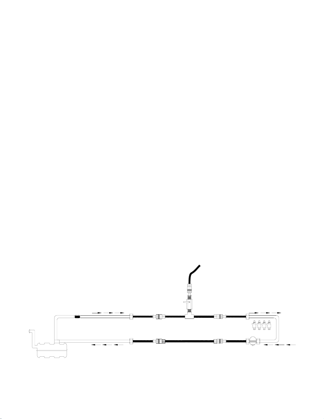
FLOW & WIRING DIAGRAM
Page 29
 Loading...