

Page 1
Operation Manual
ELF-1
E
vap Leak Finder
RTI Technologies, Inc.
10 Innovation Drive
York, Pennsylvania 17402 USA
Phone: 717-840-0678
Web-site: rti@rtitech.com
035-81259-00
Page 2

SAFETY PRECAUTIONS & HIGH PRESSURE WARNINGS
i Pay close attention to ALL warnings, as serious injury or
damage could result! Throughout the ELF-1 Operation
Manual, the symbol shown at right will designate where
particular attention should be paid and caution should be
exercised.
i Be aware that even at the relatively low pressures delivered
by the ELF-1, improper use can cause permanent damage to
some systems and components, and can be hazardous to the
operator and others in the vicinity.
i Under no circumstances should the Pressure Regulator be set fully open at 15
PSI when initially applying pressure from the ELF-1 to a system of any kind.
Always start with a very low pressure and gradually increase it. Always observe
the amount of component deflection taking place under pressure.
i Never leave any system or component under high pressure. Avoid leaving the
ELF-1 hoses and power cables connected to the vehicle under test when not
in use for extended periods of time.
i When conducting EVAP testing of the vehicle fuel vapor recovery system, it is
STRONGLY RECOMMENDED that a non-combustible inert gas – such as
nitrogen – be used instead of shop air. Use of shop air may create a HIGHLY
DANGEROUS situation which will support the combustion of the volatile fuel
vapors in the EVAP system, resulting in serious personal injury and damage.
i Always follow the vehicle manufacturer’s recommendations and any required
test procedures when testing the vehicle EVAP system.
i EVAP testing must comply with any applicable Federal and State regulations.
i Always wear safety goggles when applying pressure to a system or component.
i Do NOT tamper with or modify any of the ELF-1 components, including hoses,
cables or other replacement parts. This will void the warranty, and may cause
the unit to malfunction or to incur damage to the vehicle under test or other
property.
i Never use the ELF-1 on an engine that is running.
i The ELF-1 should ONLY be used with RTI Patented Fluid
Part Number: 438100 (4 oz bottle) or 438115 (6 Bottles)
i The ELF-1 should only be operated and stored in the upright position.
Page 3
INDEX
Use Caution when Working with High Pressure ......................... 1
Leak Testing Techniques ........................................................... 1
Control Devices .......................................................................... 2
Initial Set up ............................................................................... 3
Calibration & Internal Leak Check .............................................. 3
Modes of Operation
1 PSI Mode .......................................................................... 3
3 PSI Mode .......................................................................... 4
4-15 PSI Mode .................................................................... 5
Flow Meter ................................................................................. 5
Air Flow Valves .......................................................................... 5
Leak Flow Confirmation ............................................................. 5
Pressure & Air Flow Charts ........................................................ 6
Fog Chemical - Low Level ......................................................... 7
The Many Uses for ELF-1
EGR Valves ......................................................................... 7
Fuel Injectors ....................................................................... 7
Base Gaskets ...................................................................... 7
Air Intake Mass Flow Sensor ............................................... 7
Vacuum Lines - Intake Manifold - Plenum ........................... 8
Engine Mechanical - Head Gasket - Cooling System .......... 8
Engine Mechanical - Head Gasket Between Cylinders ....... 8
Engine Mechanical - Head Gasket - Coolant to Oil ............. 9
Engine Mechanical - Cylinder Condition .............................. 9
Oil Leaks ............................................................................. 9
Evaporative Emissions Systems ......................................... 10
HVAC Controls ................................................................... 10
Hoses & Heater Cores ........................................................ 10
Air Conditioning Systems ................................................... 10
Parts List - With Part Numbers ........................................... 11
SAFETY PRECAUTIONS & HIGH PRESSURE WARNINGS
PLEASE!
Review the important information on the preceding page.
SAVE ORIGINAL PACKAGING IN CASE ELF-1 NEEDS TO BE RETURNED TO RTI FOR REPAIRS
Page 4

USE CAUTION WHEN WORKING WITH HIGH PRESSURE
ELF-1 is capable of supplying over 15 PSI of pressure when the Pressure Regulator
is fully opened. While this may not seem to be a very high pressure reading when
compared to some pressure levels, it is very high when exposed to systems and
components that were not designed for high pressure.
Components such as a fuel tank will certainly be distorted at 15 PSI, and may even
rupture. Technically, 1 PSI, when fed into a 12 inch cube (tank) has a net force of 144
lbs on each side of the cube. Therefore, a 15 PSI feed into the same cube will have
(15 x 144) 2160 lbs of force applied to each side.
Consider the dimensions of a fuel tank. If the dimensions were say 9 inches high by 18 inches deep
by 30 inches long - the top and bottom (18 x 30) would each have a total force of 540 lbs (at 1 PSI) and
8100 lbs (at 15 PSI) pushing against them.
Consider raising a 4,500 lb car on a hydraulic lift, with a piston that is about 10 inches in diameter. The
piston area is (Pi R2) or 79 square inches. Multiply this by an air supply of 125 PSI (125 x 79) and the
potential force of 9,875 lbs forces the piston (and the car) into the air.
That’s the basic principle that causes a piston to lift many times its potential. The same principle may
be a destructive force when used incorrectly. USE PRESSURE CAREFULLY.
ELF-1 has been designed and built by automotive technicians, for automotive technicians. It is NOT
a tool for an amateur or do-it-yourselfer.
It is essential that the operator reads and understands the instructions provided here, as well as the
concepts of pressure and flow testing. Failure to read and understand ALL of the following information
will result in unsatisfactory performance from ELF-1. It may also lead to damaging systems and
components via excessive air pressure.
LEAK TESTING TECHNIQUES
ELF-1 uses a specially formulated fog liquid. The results are different than any previous smoke-based
leak detector.
ELF-1 is not a smoke machine. It generates a highly reflective fog that can be spotted easier when
exiting a leak. A white light is supplied that will reflect off the reflective fog to quickly home in on any
leaks.
The simple technique for using the white light most effectively is as follows:
Turn the light on when ready to begin locating a leak. Shine the light in the direction of the suspected
leak to spot any air movement in the light beam, then move the beam in the direction of the leak.
The smaller the leak, the faster the stream of fog will be, making it more difficult to see. Move a little
further away from the suspect area if air movement is not detected. As the fog movement slows down,
it will gather and be more visible.
Because of the formulation of the fog, it is quite likely that the leak may be located as the internal
pressure of the system/component being tested drops to near zero. At or near zero, the fog is not being
forced out of the leak, it therefore will drift out slowly and accumulate in the area of the leak. This is an
excellent opportunity to find the leak at this time.
Repeat the process if the fog dissipates before the leak is seen. This requires a quick (2-3 seconds)
shot of fog to set the process in motion again. This may be repeated as often as necessary.
Page 1
Page 5
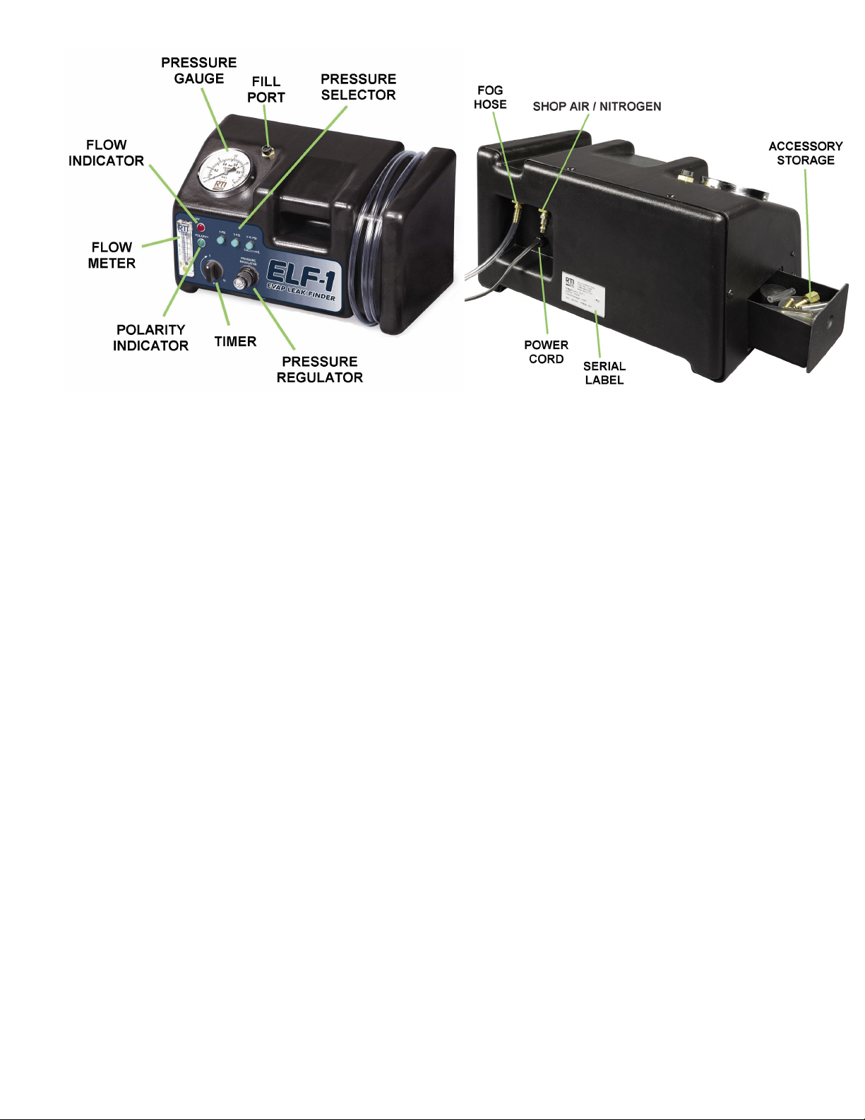
CONTROL DEVICES
Pressure Regulator: Regulates air pressure. Pull control knob away from cabinet and rotate in
desired direction. It locks in position when the control knob is released.
Timer: Power is turned on when the knob is turned clockwise to set a time period
up to ten minutes. It can be turned counterclockwise to turn off power.
Polarity Indicator: Illuminates when power cable is correctly connected to a 12 VDC battery.
Always ensure the red clamp is attached to the positive battery post and
the black clamp is attached to the negative battery post.
Flow Meter: A small floating ball indicates when air is flowing. The ball indicates a
positive air flow if there is a leak internally to ELF-1 during initial setup or
in the external system during a leak test.
Flow Indicator: Illuminates as the system under test is being pressurized when in the 1 or
3 PSI mode. Turns off when 1 or 3 PSI is attained. It will illuminate
continuously when in the 4-15 PSI mode.
Pressure Gauge: Indicates pressure of the air or fog.
Fill Port: Unscrew cap to fill ELF-1 with Fog Chemical.
Pressure Selector: Three selectors - 1, 3 or 4-15 PSI. Any one of the buttons can be pressed
to select the pressure of the fog during a leak test.
Page 2
Page 6

INITIAL SET UP
It is essential that ELF-1 is set up properly each time it is used. Failure to adhere to
the following instructions will result in inaccurate diagnosis and potential damage
(and possible destruction) to individual systems and components.
The Pressure Regulator is adjustable from a minimum of zero PSI to a maximum of
15 PSI. Extreme care must be taken to ensure that pressure settings in all modes
are appropriate for the system or component being tested.
Always turn the Pressure Regulator all the way counter-clockwise to zero before
connecting the air (or nitrogen) supply and before putting ELF-1 away.
ELF-1 ships with 2 ounces of Fog Chemical inside the unit. A 4 ounce bottle
for refilling also ships with the unit. DO NOT ADD any Fog Chemical until
needed (when fog is not produced). Refer to the instructions on Page 7.
CALIBRATION AND INTERNAL LEAK-CHECK
It is necessary to establish that there are no leaks inside ELF-1 before starting to locate a leak in an
external system.
Ensure that the Pressure Regulator is turned all the way counter-clockwise. Pull the Pressure Regulator
control knob away from the cabinet and turn.
Attach the battery clips to the battery and connect to shop air (or nitrogen) supply.
Set the Timer to 5 minutes.
Press the 4-15 PSI Pressure Selector (CALIBRATE is printed under the selector as a reminder).
Place finger over end of the clear hose and slowly turn the Pressure Regulator clockwise until the
pressure on the Pressure Gauge indicates 10 PSI.
If the pressure rises above 10 PSI, release air from hose by momentarily lifting finger. Turn the
Pressure Regulator counter-clockwise one turn and start again.
While a very small amount of leakage is allowed, the pressure must remain steady for the remainder
of the timer setting. ELF-1 is ready for use once this is accomplished. Should pressure drop too quickly,
excessive internal leakage is indicated.
MODES OF OPERATION
1 PSI MODE
This mode is for basic testing of evaporative emissions system integrity. Most manufacturers label their
EVAP systems with a 1 PSI maximum warning. When this mode is selected, pressure is internally
diverted through the 1 PSI cut-out switch. Flow is automatically stopped once 1 PSI is reached within
ELF-1 and the system being tested. More pressure is not applied until the 1 PSI pressure switch resets.
The pressure switch resets when the pressure drops to approximately 0.8 PSI. ELF-1 will begin
supplying pressure again once the pressure drops below this value.
The Flow Indicator will be illuminated whenever flow is enabled. It goes off when the mode pressure
limit is reached.
Page 3
Page 7

Fog will be flowing when the Timer is activated and the Fog Tube is connected to the system. The Flow
Indicator will be illuminated. The actual flow will be displayed on the Flow Meter, and increasing
pressure will be indicated by the Pressure Gauge.
Pressure will reach 1 PSI and the pressure switch will stop any further flow assuming that there is no
leak in the system. The Flow Indicator will go off. Observe the Pressure Gauge to see if the 1 PSI of
pressure is dropping. A leak is indicated if the pressure drops.
If the system can hold this pressure for 3 minutes it can be assumed that there is no leak.
Should there be a leak in the system, the pressure will decrease about 0.20 PSI and the pressure
switch will activate causing ELF-1 to begin applying pressure.
Constant on/off cycling of ELF-1 indicates that a leak is present. The size of the leak can be estimated
by using the Flow Meter, the Pressure Gauge and the Leak Chart on Page 6.
ELF-1 will not shut off automatically if the system never reaches 1 PSI. This indicates that the system
being tested is not filled or the leak is so large that the amount of fog flowing from ELF-1 into the
system can not raise the pressure to 1 PSI.
Some systems may have a relief valve that relieves pressure in the system well
under 1 PSI. Volkswagens, for example, relieve at about 0.4 PSI. It may be
necessary to remove the line or pinch it off to seal the system.
Further Investigation: Select the 4-15 PSI mode and very slowly increase the
fog flow with the Pressure Regulator. When the Flow
Meter ball stays in one steady position, the current
pressure and air flow indicated can be used to determine
the size of the leak using the Leak Chart.
3 PSI MODE
ELF-1 operates exactly the same in the 3 PSI mode as it does in the 1 PSI
mode. The major difference is that the pressure switch will stop flow at 3 PSI.
The pressure switch resets when the pressure drops to approximately 2.6 PSI. ELF-1 will begin
supplying pressure again once the pressure drops below this value
The 3 PSI mode may be more useful for testing EVAP systems that have established leaks.
The pressure Gauge may occasionally indicate a higher pressure than
selected. This is the result of pressure backing up from the fuel tank and
system flexing. This is not harmful to ELF-1 and may be ignored.
Page 4
Page 8

4 - 15 PSI MODE
When in this mode, internal pressure switches are by-passed enabling full control over the amount of
pressure and/or volume that ELF-1 will supply.
It is very important that the Pressure Regulator is turned all the way down
(counterclockwise) before applying fog in this mode. Failure to observe proper
procedures may result in damage, distortion and destruction of components
not designed to be pressurized to 15 PSI.
Never hook ELF-1 to any system or component with the regulator setting in an
unknown position. A sudden, excessive increase in pressure will result in
damage to the component.
FLOW METER
The markings on the front of the Flow Meter provide an approximate indication of the amount of air
(Standard Cubic Feet per Hour) that is being fed into the system being tested.
The 0.020 & 0.040 markings are indicative of the approximate amount of flow that would be allowed
by a leak of that size at 1 PSI. This represents a round hole of 0.020 inch or 0.040 inch. Variation can
be expected from leak to leak as most leaks are not simple, round holes.
Once a leak has been established, switch to the 3 PSI mode (more fog delivery) or stay in the 1 PSI
mode if the leak has been spotted.
AIR FLOW VALUES
The air flow will generally be in the 15 to 18 SCFH range when the Pressure Regulator is set correctly.
It is possible to measure the rate of a leak by adjusting the Pressure Regulator while in the 1 or 3 PSI
mode. Flow has been adjusted to match the leak when ELF-1 is continually cycling.
ELF-1 can deliver well over 30 SCFH, when the Pressure Regulator is opened fully. A typical empty
fuel tank may be in the 4 cubic feet area. It would appear that it would take about eight minutes (60\30
x 4) to fill the tank. However, under real conditions, with no resistance, the tank will reach about 1 PSI
in about 2 to 3 minutes.
LEAK FLOW CONFIRMATION
This feature incorporates a highly accurate Flow Meter which is used with one of the two internal
automated pressure switches to assess the suspected leak.
Hook up the fog tube with adapter to the system to be tested. Select one of the two controlled pressure
ranges (1 PSI or 3 PSI). The button will illuminate when pressed.
When the selected pressure is reached, the application of pressure is automatically cut out, indicating
that the system has reached the target pressure.
Any leak will lower the pressure that is trapped in the system. When this occurs, the sensitive pressure
switch cuts the fog supply back in. As the system cuts back in, the ball in the Flow Meter is blown high
up in the display, indicating that there is in fact a leak. This may be repeated as often as required. The
more frequently the ball bounces the larger the leak.
Page 5
Page 9

PRESSURE & AIR FLOW CHARTS
The following information is an outline of the relationships between the flow of air, the pressure applied
and the size of a leak that influences them.
In all cases assume that any leak size described is the equivalent area of the diameter of the leak. Of
course few leaks are round, but all have an open area of leakage.
LEAK CHART 1
LEAK SIZE PSI SCFH
0.020 1 0
0.020 2 0
0.020 3 0
0.020 4 1
0.020 5 2
0.020 6 3
0.020 7 4
0.020 8 5
0.020 9 6
0.020 10 7
0.020 11 8
0.020 12 10
0.020 13 12
0.020 14 13
0.020 15 15
Leak Chart 1 provides a better idea of how air flow
and pressure are influenced by the size of the leak.
This chart represents a 0.020 inch diameter leak,
which is so small, it will not register on the Flow
Meter until 4 PSI is applied. At this point it registers
just 1 SCFH (Standard Cubic Feet per Hour).
As the applied pressure is increased, so does the air
flowing through the leak increase.
Unfortunately, such a leak has the effect of
dissipating fog and making it difficult to see. It’s
there, but very fine. The white light will be helpful in
this scenario.
LEAK CHART 2
LEAK SIZE PSI SCFH
Leak Chart 2 shows the increase in air flow for a
0.040 1 9
0.040 2 12
0.040 3 16
0.040 4 18
0.040 5 20
The above Leak Charts are for illustration of flow rates at different
pressures for two different sizes of leak.
Do not increase pressure beyond the maximum rated pressure of the
vehicle component being tested.
0.040 inch leak.
Note the large difference in air flow, even though the
diameter of the leak is just doubled. The actual flow
increases dramatically.
Page 6
Page 10

FOG CHEMICAL - LEVEL LOW
A new charge of fog chemical needs to be added when ELF-1 stops providing fog. Remove the cap
from the fill port on the top of ELF-1 and add 3 ounces from the 4 ounce bottle. Re-order a new bottle
for the future. The one ounce left in the bottle is a reserve in case a new bottle was not ordered.
Order RTI Part Number: 438100 (4 oz Bottle) or 438115 (6 Bottles)
Never overfill ELF-1. The unit will need to be returned to the factory and is not covered under warranty.
ELF-1 ships with 2 ounces of Fog Chemical inside the unit. A 4 ounce bottle
for refilling also ships with the unit. DO NOT ADD any Fog Chemical until
needed (when fog is not produced).
THE MANY USES FOR ELF-1
EGR VALVES
One of the most common uses for ELF-1 is detecting vacuum or exhaust leaks in and around EGR
valves. Frequently a drive ability or emissions related problem (especially NOx related) may be caused
by an inoperative EGR Valve (defective diaphragm, leaking solenoid, leaking vacuum line). By applying
ELF-1 to the diagnosis, a visual result will be seen quickly.
It’s also possible to fill the exhaust system from the tailpipe forward to reveal EGR related leaks. This
will of course locate any exhaust leaks at the same time. Treat each branch separately for true dual
exhausts. Plug one of the tailpipe outlets if the branches are joined.
FUEL INJECTORS
A port fuel vehicle that has been overheated may have hardened or broken O-rings around one or more
injectors. Inserting fog into the intake manifold (plenum) will easily point this condition out, once again
making a difficult diagnosis, relatively easy. Don’t forget that some intake and exhaust valves will be
open, so fog may eventually appear at the exhaust and potentially at or around the throttle body area.
BASE GASKETS
Fog introduced into the intake manifold at virtually any point will fill the area and find a way out if it is
available. A carburetor or throttle body base gasket that is leaking will be easy to spot. In some cases
(when a supplied adapter is not suitable), it will be worthwhile to remove the air cleaner and seal the
air intake with a plastic bag and a few wraps of tape.
AIR INTAKE WITH MASS AIR FLOW SENSOR
As many port fueled vehicles age, the potential for a drive ability problem, related to false air, increases.
False air occurs when a leak between the mass airflow sensor and the throttle body occurs. This could
be the result of degenerating air intake material, or as simple as a clamp that has lost adjustment or
tension and no longer seals.
False air allows unmeasured oxygen into the intake, which leans out the air to fuel ratio while lowering
the average oxygen sensor readings. The natural tendency therefore is for the on-board computer to
add additional fuel, which the engine does not need and cannot completely burn. Over time, this
situation will eventually lead to an overloaded or failed catalytic converter.
Fill the intake manifold with fog with the engine off. As the manifold fills, fog will migrate past the throttle
plate and into the intake ducting between the throttle body and the air cleaner. Carefully observe any
leaking fog. Any leaks between the air flow sensor and the throttle body are false air leaks.
Page 7
Page 11

VACUUM LINES - INTAKE MANIFOLD - PLENUM
Today’s vehicles are true engineering marvels. The sealing on and in the various systems has improved
tremendously over the last 10 to 15 years. Systems that leaked on a regular basis no longer leak at all,
and occasional leaks have become harder to find. Oil leaks are now almost as rare as fuel leaks and
can be much harder to pinpoint.
On-board computer systems may be instrumental in masking a drive ability problem. Frequently these
are repaired or components are replaced (such as a catalytic converter) that have failed with no
apparent reason.
The previous section discussed false air. Likewise, an intake leak can cause components to fail, drive
ability problems and difficult-to-diagnose emissions problems, especially idle related problems.
The most ideal manner to check an intake manifold is to go in through the fuel pressure regulator
vacuum hose, if it’s available. The PCV hose or main power brake booster hose are okay too. Remove
the hose at the regulator and use the large clear hose to adapt. Fill the manifold with fog. After about
30 seconds, any fog observed in the engine compartment must be investigated. Pay particular attention
under the plenum if possible. A frequency type leak detector will often pick out potential leaks in this
area, but can not usually pinpoint them.
Of course, a suspected leak at a vacuum line or any vacuum controlled device can be easily spotted
once it is filled with fog.
Never assume that there is only one leak at a time.
The above procedure does not take into consideration vacuum lines or
devices controlled by a solenoid or a temperature or vacuum valve. They
should be treated individually.
ENGINE MECHANICAL - HEAD GASKET - COOLING SYSTEM
A head gasket, or similar failure, may be diagnosed by filling either the crankcase or the cooling system
with fog. There are a number of ways to approach this diagnosis.
Fog will not always displace liquid. The area should be drained to
check for any liquid leak.
If it’s suspected that coolant is being lost from the cooling system into a combustion chamber, try the
following.
Drain the cooling system lower than the head gaskets. Remove the suspect spark plugs. Use the
appropriate adapter to seal the radiator filler neck with ELF-1 in the radiator. Allow about two minutes
of operation then carefully observe the intake area, the spark plug holes and the tailpipe area. If fog is
observed at either exhaust or intake, a cracked head or valve seat may be indicated. Fog from a spark
plug hole indicates a head gasket leak.
ENGINE MECHANICAL - HEAD GASKET BETWEEN CYLINDERS
Removing the spark plugs will reveal the fog path from one side of the leak to the other. Bring one of
the suspected cylinders up to TDC on compression and apply ELF-1 to that cylinder. Fog will appear
at the cylinder if the gasket or cylinder head leak is between cylinders or at the intake or exhaust,
depending on the current position of the valve train. Repeat the procedure for the other cylinder for an
absolute diagnosis.
Page 8
Page 12

ENGINE MECHANICAL - HEAD GASKET - COOLANT TO OIL
If coolant is found in the engine oil, there are a number of potential paths that could leak to cause this
condition. While impossible to be definitive about the exact path, it is usually possible to confirm that
the condition exists.
Applying ELF-1 to the radiator (after draining the coolant) will eventually cause fog to appear at either
the oil filler location, the dipstick tube or the PCV valve. If all three components are left in the open
position, observing where the fog first appears may provide clues to the path of the leak.
ENGINE MECHANICAL - CYLINDER CONDITION
A compression test is often performed where the cylinders were uneven but there appears to be no
mechanical problem. Any leakage can be observed by applying ELF-1 to each cylinder.
Remove all of the spark plugs, remove the air cleaner from the carburetor - throttle body, pull the
dipstick tube and the oil filler cap. Perform a dry compression test and record the readings.
Starting with the lowest reading cylinder, bring each cylinder to TDC on compression before applying
ELF-1. Apply for about one minute to each cylinder in turn. Ideally, there should be no fog anywhere
except inside the cylinder being evaluated. Fog at the throttle area indicates intake valve leakage. Fog
at the exhaust would indicate exhaust valve leakage and fog at the oil filler or dipstick tube would
indicate piston ring leakage.
OIL LEAKS
Even on a very dirty engine, filling the crankcase with fog via the dipstick tube will eventually reveal any
oil leaks. This allows planning the repair better, knowing what needs to be done. Previously discussed
were recent improvements in sealing methods employed by the manufacturers. Often an oil leak will
not be obvious, as in replacing a valve cover gasket a number of times, only to eventually find that the
intake manifold is the real culprit.
Note that ELF-1 can pump up to 15 PSI into a test area. Do not apply
excessive pressure into an oil system. It is possible to damage or
dislodge seals and gaskets with excessive pressure.
Apply ELF-1 to the dipstick tube for a minute or so, then watch the results. Fog will eventually appear
at the real leak, not necessarily where most of the oil is. Of course, always observe the old rule that the
leak will usually be at the highest physical point of the wet area, even though in some cases it can not
be seen.
Adapters are supplied to plug off the PCV System (both Valve & Fresh Air Intake). If the oil leak isn’t
found with low pressure testing, there is the option of increasing the pressure, by plugging off the PCV
System and trapping the fog in the oil system.
There are no published specifications for pressurizing an oil system. Some
large area seals and gaskets will be under stress if they are exposed to
excessive pressures. Use extreme caution
Page 9
Page 13

EVAPORATIVE EMISSIONS SYSTEMS
Basically there are two types of EVAP Systems. Vacuum operated and electronically operated. Both
types are designed to ensure that gasoline fumes from the fuel tank do not get into the atmosphere.
Earlier vacuum operated systems simply provide a vacuum signal from the engine, which opens a valve
(diaphragm) on the top of the canister that allows the stored (adsorbed) gasoline fumes to be sucked
into the engine once it is running.
Electronic systems use a computer controlled solenoid in place of the older vacuum control valve.
Additionally OBDII Systems utilize an in-tank vacuum/pressure sensor that is monitored by the on-board
computer, as well as additional venting solenoids. Most manufacturers recommend that any pressure
applied to the system be kept below 1 PSI. ELF-1 will accomplish this in the 1 PSI mode.
The quickest & simplest method, regardless of which type of system being testing,
is to fill the system through the EVAP port with the appropriate adapter. This will
allow fog to fill the entire system, without disturbing it, thus checking the gas cap
too. In some cases, opening the gas cap while filling the system with fog may be
advantageous, since this may help distribute fog more evenly throughout the
system.
A Custom brass EVAP port adapter is supplied.
ELF-1 provides sufficient volume to fill the entire system in just a few minutes.
An alternate option is to fill the tank via the fuel cap. It is recommended that a shop cloth be used as
a gasket, along with the appropriate supplied rubber adapter. The cloth will also protect against losing
the adapter in the tank.
Success in locating leaks with higher pressures can be realized by isolating or removing components
from the vehicle and increasing the pressure. Such defects as faulty or failed seam welds in plastic
evap canister housings may be found in this manner.
HVAC CONTROLS
Vacuum controlled HVAC systems may leak. In many cases it’s even possible to hear the leak.
Pinpointing it under a crowded dashboard may be more difficult. Applying fog to the main vacuum
source will usually point out the leak.
HOSES & HEATER CORES
While in most cases a heater hose leak is obvious, many later vehicles have hoses and piping routed
in hard to see and reach locations. Tighter engine bays and newer configurations have forced the use
of metal tubing to replace the rubber type heater hose. Frequently, disconnecting just one end of a
heater hose (empty of coolant) and applying ELF-1 to it, will provide an answer to a leak location. If not,
by disconnecting both heater hoses at their source, then plugging one end, ELF-1 will fill the area and
will often reveal the leak.
Heater cores can be tested quite simply. Drain and disconnect the lower hose. Turn on the ignition and
the blower motor on low with defrost selected if possible. Apply ELF-1 to the heater hose while
observing the closest defroster duct. In some cases, it may be necessary to run the engine for this test.
If so, remove both heater hoses from the heater core and join them together (usually with a flushing
T). Plug one of the heater core pipes and apply fog to the other. Start the vehicle with the defroster and
low blower speed selected.
AIR CONDITIONING SYSTEMS
Not suitable for evaporator or refrigerant line porosity leaks.
Page 10
Page 14

Parts List - With Part Numbers
Complete Adapter Set: 438130
High Intensity White Light Fog Chemical - 1 Bottle: 438100
438140 Fog Chemical - 6 Bottles: 438115
8 ft Clear Fog Hose: 438125
Page 11
 Loading...