

Page 1

OPERATION
&
MAINTENANCE
MANUAL
CSC Series
Coolant Service Center
Manual P/N 035-80318-00
Page 2

Introduction
The CSC10R is a time saving member of RTI 's family of coola nt handling equipment. This portable unit
safely drains and refills automotive engine cooling systems in a portion of the time it takes for
conventional methods. When properly opera ted, this unit induces no air or pressure into the engine's
cooling system. No hose cutting or tee is required - gravity and the engine's own water pump perform
the service.
The filtration-type Recycling Center incorporated into the rear of the unit takes this process one step
further. A special formulated advan ced inhibitor package is added to the filtered coolant for adjustment
of the pH and to replenish depleted inhibitors, buffers, anti-foaming agents, and dyes. Once mixed, the
properly recycled coolant meets or exceeds ASTM standards.
YOUR RESPONSIBILITY
The user of a CSC10R is solely r esponsible for all environmental and safety concerns, or laws pertaining
to the use and disposal of antifreeze/coolant handled or produced by this equipment.
Do your part for the environment. Recover, recycle when possible, and dispose of wastes in a proper
manner.
Waste co olant must be evaluated prior to recycling... DO NOT process if waste coolant contains
non-antifreeze contaminates such as OIL, GASOLINE, SOLVENTS, etc.
Table of Contents
Introduction ..................................................................1
Safety Precautions .............................................................2
Assembly ....................................................................3
Sequence of Operation..........................................................4
Performing a Quick Change......................................................5
Use of Evacuation Pump ........................................................6
Attach to Vehicle ..............................................................6
Special Cooling Systems ........................................................7
Performing the Quick Change ....................................................8
Draining the Waste Coolant Drum ................................................9
Using the Recycling Center .....................................................10
Evaluating Waste Coolant for Recycling...........................................10
Starting the Recycling Process...................................................11
Adding Reinhibitor ...........................................................11
Maintenance Schedule .........................................................12
Warranty....................................................................13
Parts List ...................................................................14
Freeze Point Adjustment Chart ..................................................15
- 1 -
Page 3

Safety Precautions
| WARNING:
FAILURE TO FOLLOW THESE PRECAUTIONS CAN RESULT IN
SERIOUS INJURY OR DEATH.
`
` Read and understand the operation manual completely before operating this unit.
``
` Always wear proper eye and skin protection when operating and maintaining this equipment.
` Hazardous voltages present. Use onl y with a grounded electrical outlet and grounded extension
cords. Do not remove the ground prong from the plug.
` Take precaution s to keep clothing, hair, hands, hoses, etc. Away from all moving parts on the
vehicle.
` Automotive cooling sys tems can be under pressure and extremely hot. Allow the cooling sy stem to
cool down and use extreme caution when removing caps and hoses.
` Antifreez e/coolants and inhibitors are poisonous to people and animals and are also corrosive. Clean
up any spills immediately.
` Before using the RTI Automotive Re inhibitor for CSC10R, read all warnings and precautions on the
bottle's label.
| CAUTION:
FAILURE TO FOLLOW THE PRECAUTIONS AS OUTLINED IN THE
OPERATION MANUAL CAN RESULTS IN DAMAGE TO THE ENGINE,
VEHICLE OR EQUIPMENT WHICH WILL NOT BE SUPPORTED OR
COVERED UNDER WARRANTY.
` Do not allow waste coolant drum to overflow. Immediately clean up any coolant or reinhibitor spills.
Damage to the vehicle and equipment can result from the corrosiveness of coolan t and reinhibitors.
` Continuous monitoring of the Quick Change process is required. Leaving the vehicle unattended
while operating this equipment can result in damage to the engine, vehicle, and/or equipment.
` The dirty waste coolant MUST meet sp ecific requirements in order to produce an acceptable recycled
coolant product. the use of processed waste coolant that does not meet the requirements can result
in damage to the equipment or the vehicle's engine.
- 2 -
Page 4
Assembly
INSTALLATION OF SWIVEL CASTERS
Loc at e t he 4 swivel c asters and ba g of har dware that we re shipped in the F ill Bucke t on top of the unit.
Verify that the hardware bag contains 8 bolts, 8 lock-washers, and 8 nuts.
Have a helper tilt the unit on its bottom edge to install each caster. Insert the bolt from the top, secure
the washer and nut on the bottom. Tighten with a 1/2" wrench or socket.
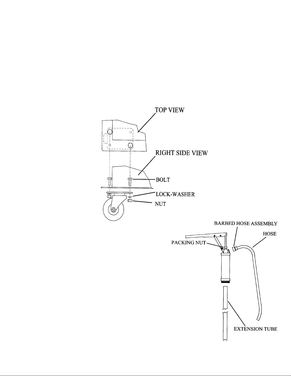
HAND PUMP ASSEMBLY
1. Remove pump from box.
2. Screw barbed hose assembly onto the pump outlet.
Attach the section of hose to the barb and tighten clamp.
3. Screw the extension tube to the bottom of the pump and
fully extend the tube.
4. Securely tighten packing nut at the top of the pump
to prevent leakage.
5. Screw pump into large opening on supplied 15 gallon
Clean Coolant Drum.
- 3 -
Page 5
Sequence of Operation
The CSC10R is a device designed to perform quick and simple
engine coolant changes on automobiles and light trucks. When
properly operated, this Quick Change can be accomplished in as
little as ten minutes. The following is the normal sequence of
operation for the CSC10R. Refer to the "Performing A Quick
Chang e" and "Using The Recycling Center" section of this manual
for complete instructions before operating your unit.
PREPARE FOR THE QUICK CHANGE - A
vehicle is pulled into the service area and the CSC10R is
positioned. An appropriate amount of new recycled coolant is
mixed in the CSC10R Fill Bucket.
USE THE EVACUATION PUMP - Waste coolant is removed
from the ve hicle's ra diator and overflow bottle using the CSC10R
Suction Hose.
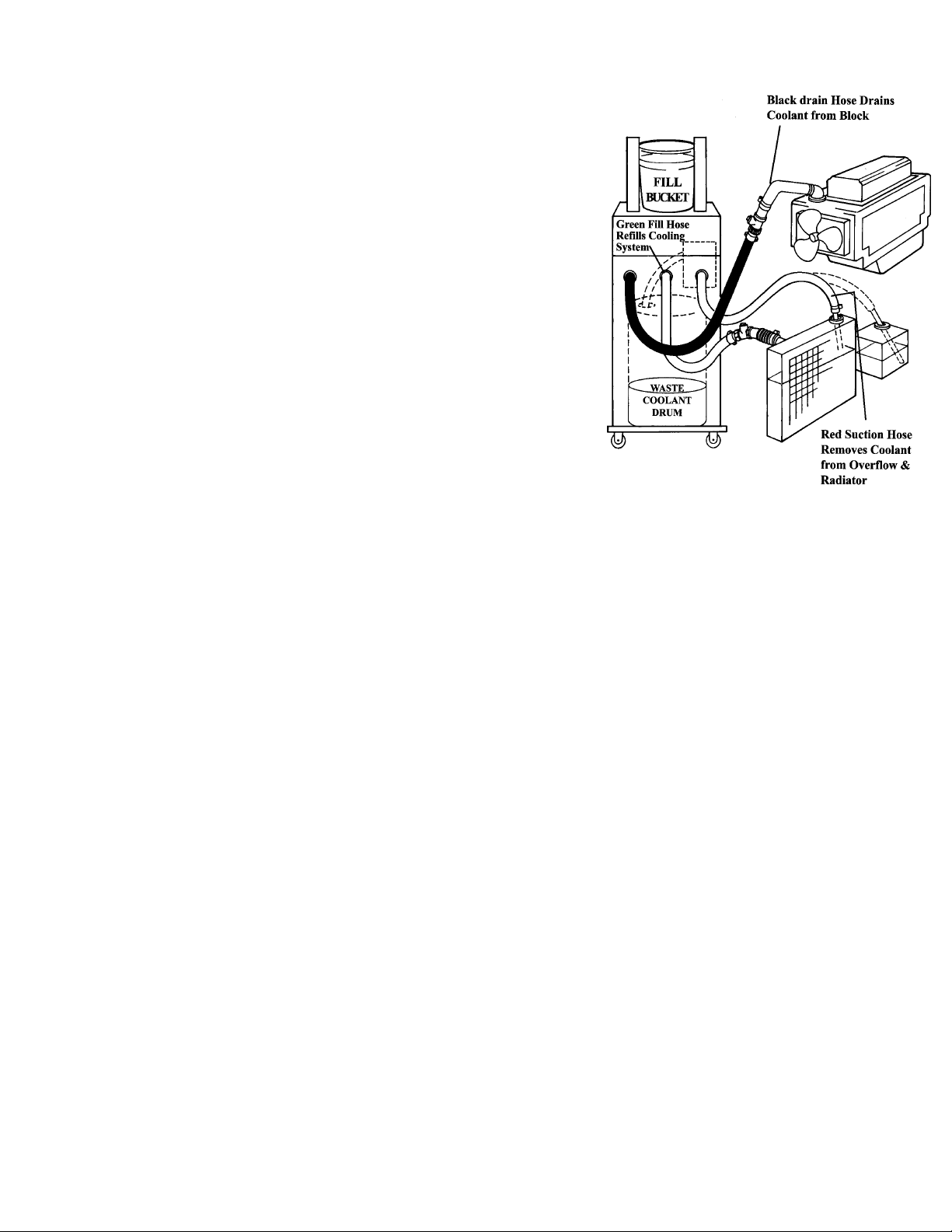
ATTACH THE CSC10R - The GREEN Fill Hose and BLACK Dra in hose are attached to the vehicle's
cooling system through a removed upper radiator hose. No hose cutting or tees are required.
PERFORM THE QUICK CHANGE - While the Drain Valve on the BLACK Drain Hose is closed,
the Fill Valve on the GREEN Fill Hose is opened and the vehicle's engine started. The Drain Valve is
opened, and the level in the Fill Bucket will drop as the new coolant displaces the waste coolant. the
waste coolant drains through the BLACK Drain Hose and into the Waste Coolant Drum in the rear of
the unit. When only two quarts of new coolant remain i n t h e CSC10R Fill Bucket, the Fill and Drain
Valves are closed, and the vehicle's engine is turned off.
DISCONNECT THE CSC10R - The CSC10R is removed from the vehicle and the vehicles's radiator
hose is re-attached.
TOP OFF - The ra diat or and over flow bottle are filled to the proper leve ls using the GREEN Fill Hose.
The engine is started to check for leaks.
RECYCLE - Once the CSC10R Waste Coolant Drum contains twelve to fifteen gallons of waste
coolant, it is time to recycle. The valve on the YELLOW Hose is o pen ed and inserted into the Clean
Coolant D ru m. T he Process Switch is turned on, and in less than ten minutes, the filtering process is
complete.
REINHIBIT - After the filtering cycle is complete, the recycled coolant is mixed with water or
antifreeze to obtain the desired freeze/boil protection. RTI's Automotive Reinhibitor for CSC10R is
added to adjust the pH and to replenish depleted corrosion inhibitors, buffers, anti-foaming agents, and
dyes. This process produces a quality recycled coolant that meets or exceeds ASTM standards.
- 4 -
Page 6

Performing A Quick Change
Following these guidelines will allow a Quick Change on most vehicles. Due to the variety of
automobile and light truck coolant system designs, slig ht variations of this procedure may be necessary.
PREPARE FOR OPERATION
1. Pull the vehicle into the servi ce area. Set the vehicle's heater controls to t he highest tem perature
setting and turn off the heater fan.
2. SHUT OFF THE VEHICLE'S ENGINE and raise the hood.
3. Verify that the Fill Valve on the GREEN Fill Hose and the Drain Valve on the BLA CK Drain Hose
of the CSC10R are both in the CLOSED position.
| WARNING
Wear proper eye and skin protection such as safety glasses and gloves.
4. Determine the total cooling system capaci ty of th e vehicle. P repare a mixture of new or recycled
antifreeze and water equal to the system capacity. Pour the mixture into the Fill Bucket. Place the
lid on the Fill Bucket.
NOTE: Most engine manufacturers' recommend a mixture of 50% antifreeze and 50% water.
Use distilled or demineralized water to prevent scale and mineral build-up.
5. Check the level in the Waste Coolant Drum in the rear of the CSC10R to v eri fy tha t it is not too full
to hold another coolant change.
| CAUTION:
Do not allow the Waste Coolant Drum to overflow. Immediately clean up any spills.
Damage to the vehicle and equipment can result from the corrosiveness of the coolant.
6. Wheel the CSC10R to the front of the vehicle and plug the electric cord into a 115 volt, 60 Hz
grounded receptacle. Use a 16 gauge (minimum) grounded extension cord if necessary.
NOTE: The CSC10R relies on gravity to fill the vehicle's cooling system. The TOP of the
vehicle's radiator must be L OWER than the BOTTOM of the Fill Bucket on the CSC10R
for the coolant change to occur.
- 5 -
Page 7

USE OF THE EVACUATION PUMP:
| WARNING:
Automotive cooling systems can be under pressure and extremely hot. Allow the vehicle's
cooling system to cool down and use extreme caution when removing caps and hoses. Consult
the vehicle manufacturer for recommended procedure on removing the radiator cap.
1. Squeeze the vehicle's upper radiator hose to determine the amount of pressure in the system. If the
hose is hot and hard, allow the cooling system to cool down before proceeding.
2. Carefully remove the vehicle's radiator cap.
3. Insert the Plastic Wand on the RED Hose into the radiator. Turn the CSC10R Evacuation Pump (the
switch is located on the front bevel of the unit) and remove the liquid from the radiator until the
liquid level is below the UPPER radiator hose (a pproximately two quar ts). Turn off the Evacuation
Pump and replace the radiator cap.
|||| CAUTION
Do not remove too much liquid from the radiator.
Allowing air to enter the LOWER radiator hose can
result in damage to the vehicle's engine.
|||| CAUTION
Never allow the Evacuation Pump to operate without
liquid. Running the pump dry will cause premature
wear or damage to the pump and is not covered under
warranty.
4. Locate the vehicle' s coolant overflow bottle and remove its cap. Insert the P lasti c Wand on the RED
Suction H os e into the ove rflow bottle, turn on the Evac uation Pump, and remove as muc h liquid as
possible. Turn off the pump and return the RED Suction Hose to its clip. Replace th e c ap o n the
overflow bottle.
HINT: If the overflow bottle contains sludge, loosen it with water sprayed from a hose.
ATTACH THE CSC10R TO THE VEHICLE - CONVENTIONAL COOLING SYSTEMS:
1. Loosen the hose clamp that holds the UPPER radiator hose to the radiator. Use a nut-driver,
screwdriver, or hose clamp pliers (depending on the type of clamp) to loosen the clamp.
2. Pull loose and remove the UPPER radia tor hose from the vehicle's radiator. Be careful not to damage
the radiator inlet or hose while removing.
- 6 -
Page 8

3. Attach the BLACK Drain Hose from the CSC10R to the removed, open end of the UPPER radiator
hose by inserting its Step Adapter into the UPPER radiator hose. With a hose clamp, seal the UPPER
radiator hose tightly to the "best fit" step on the Step Adapter.
HINT: In some cases, the size difference between the UPPER
radiator h ose and the Step Adapter may seem too large. I t
is OK to tigh t e n down the hose clamp to seal up to a 1/4"
gap. A "worm-gear" type clamp tightened with a nut
driver works best.
4. Attach the "best fit" Fle xible Hose Adapter to the radi ator's inlet
and secure it tightly using the supplied hose clamp. Be careful
not to damage the radiator's inlet.
5. Attach the GREEN Fill Hose from the CSC10R by inserting its
Step Adapter into the open end of the Flexible Hose Adapter.
With a hose clamp, seal the Flexible Hose Adapter tightly to the
"best fit" step on the Step Adapter.
|||| CAUTION
Check and ensure that all hoses, rags, tools, or other objects
will be clear from moving parts of the vehicle.
ATTACH THE CSC10R TO THE VEHICLE - SPECIAL COOLING SYSTEMS:
HINT: Some vehicles with non-conventional cooling systems require a different procedure for
attaching the CSC10R. Some examples are:
Mid or rear engine vehicles with the radiator in the front of the vehicle
Radiators that do not allow access to the upper radiator hose.
Pressurized overflow systems where the overflow bottle is capped, not the radiator.
1. Loosen the hose clamp that holds the UPPER radiator hose to the thermostat housing on the engine.
Use a nut-driver, screwdriver, or hose clamp pliers (depending on the type of clamp) to loosen the
clamp.
2. Pull loose and remove the UPPER rad i a t o r h ose from the vehicle' s thermostat housing inlet. There
may be liquid in the hose - place a supply of rags under the hose to catch any spilled coolant. Be
careful not to damage the radiator hose while removing.
3. Attach the GREEN Fill Hose from the CSC10R to the removed, open end of the UPPER radiator
hose by inserting its Step Adapter into the UPPER radiator hose. With a hose clamp, seal the UPPER
radiator hose tightly to the "best fit" step on the Step Adapter.
- 7 -
Page 9

HINT: In some cases, the size difference between the UPPER radiator ho se and the Step Adapter may
seem too large. It is OK t o t ighten down the hose clamp to seal up to a 1/4" gap. A "wormgear" type clamp tightened with a nut driver works best.
4. Attach the "best fit" Flexible Hose Adapte r to the thermostat housing's inlet and secure it tightly
using the supplied hose clamp.
5. Attach the BLACK Drain Hose from the CSC10R by inserting its Step Adapter into the open end
of the Flexible Hose Adapter. With a hose c lamp, seal the Flexible Hose Adapter tig htly to the " best
fit" step on the Step Adapter.
|||| CAUTION
Check and ensure that all hoses, rags, tools, or othe r obj ec ts will be c lear from moving parts
of the vehicle.
PERFORMING THE QUICK CHANGE:
|||| WARNING
Keep clothing, hair, hands, etc. away from all moving parts of the vehicle.
|||| CAUTION
Continuous monitoring of the Quick Change process is required. Leaving the vehicle
unattended while operat ing this equipment can result in damage t o the engine, vehicle and/or
equipment.
1. OPEN the Fill Valve on the GREEN Fill Hose. The lev e l i n th e Fill
Bucket will begin to drop, then stop. Keep the Drain Valve on t he
Black Drain Hose closed at this time.
2. Start the engine of the vehicle.
3. OPEN the Drain valve on the Black Drain Hose. Watch the level in
the Fill Buc ket. I f the level does not drop, or stops dropping, CLOSE
the Drain Valve. After approximately 30 to 60 seconds, RE-OPEN
the Drain Valve. Repeat this procedu re until two quarts remain in the
Fill Bucket.
NOTE: Opening and closing the Drain Valve as descr ibed will protect
vehicles with the thermostat located ahead of the water pump
("reverse flow" cooling systems). This procedure prevents the
old coolant from being pumped out of the engine block
prematurely when the new coolant is restricted by a closed
thermostat.
HINT: The coolant change can occur only if the vehicle's thermostat is open. To help get the vehicle
up to normal operating temperature, it may be necessary to raise the rpm's of the engine to
warm it up before the level in the Fill Bucket will continue to drop.
- 8 -
Page 10

4. CLOSE the Fill Valve on the Green Hose.
5. Allow the eng ine to run for 10 seconds after closing the Fill Valve, th e n
TURN THE E N GINE OFF. This lowers the coola nt level in the ra diator
to help prevent coolant from spilling when re-attaching the UPPER
radiator hose.
|||| CAUTION:
Failure to turn vehicles engine off ten seconds after closing Fill Valve
can result in damage to the vehicle.
6. CLOSE the Drain Valve on the BLACK Drain Hose.
7. Remove the CSC10R from the vehicle. reconnect the UPP E R radiator hose to the radiator (or the
thermostat housing for "special" cooling systems) and clamp securely.
8. Remove the vehicle's radiator cap and top off the radiator using the r emaining coolant in the Fill
Bucket. While holding the GREEN Frill Hose ove r the ra dia t o r ' s ope ning , SLOWLY open the Fill
Valve to allow the top off coolant to flow. Also, open t h e v ehicle's coolant ove rflow bottle and fill
to the proper level. return both caps and secure.
9. Start engine of the vehicle and check for leaks.
DRAINING THE WASTE COOLANT DRUM:
It may be necessary to occasionally drain the Was te Coolant Drum without recycling (e.g., waste coolant
does not meet minimum standards for recycling).
1. Remove the BLACK hose from the large opening of the
Waste Coolant Drum (located in the back of the machine)
and place it into a receiving container.
2. Insert the wa nd fr om the RED hose into the la rge opening
on the Waste Coolant Drum until it reaches the bottom.
3. Turn ON the Evacuatio n Pump (located on the front bevel
of the unit).
4. Allow the pump to run until all liquid is removed from the
Waste Coolant Drum.
5. Turn OFF the Evacuation Pump and return BLACK and
RED hoses to their original positions.
| CAUTION
Never allow the pump t o operate without liquid. Running the pump dry will cause premature wear
or damage to the pump and is not
covered under warranty.
- 9 -
Page 11

Using The Recycling Center (Optional)
The Coolant Recycling Center is located on the back of the CSC10R. Recycle when the Waste Coolant
Drum contains between 12 and 15 gallons. Do not allow drum to overflow.
|||| CAUTION:
Waste coolant MUST be evaluated prior to recycling. Improperly recycled coolant which does
not meet standards can result in damage to the equ i pment or the veh icl e's en gin e and i s not
supported under warranty.
|||| CAUTION:
Do not recycle hot coolant. the waste coolant must be below 1200F. Recycling hot waste coolant
can result in equipment damage.
EVALUATING WASTE COOLANT FOR RECYCLING:
1. Check the large opening on the Waste Coolant Drum for oil flo ating on the surface of the waste
coolant. Remove any oil present previous to recycling and dispose of properly.
2. Open the valve on the Yellow Hose and place it into the large opening on the Waste Coolant Drum.
3. Press the Process Switch to ON position. Allow pump to run for approx im ately 20 seconds then
switch to OFF position. This step clears the filter of liquid from the previous batch.
4. Remove nozzle from drum and pump approximately 20 ounces into the triangular measuring cup.
Observe for excessive foaming (bubbles which do not readily break or standing foam).
5. Check sample for appearance/odor, freeze point and pH.
THE FOLLOWING STANDARDS MUST BE MET TO PRODUCE AN ACCEPTABLE
RECYCLED COOLANT:
r APPEARANCE / ODOR of the waste coolant must have the distinct and characteristic appearance
and odor of antifreeze/coolant.
DO NOT process if the waste coolant contains any non-antifreeze contaminants such as oil,
gasoline, solvents, etc.
DO NOT process if waste coolant appears milky or is excessively foamy.
r FREEZE POINT of waste coolant must be at least -50F or lower. Coolants with freeze points from
-40 to +320F do not contain sufficient ethylene glycol.
r pH of waste coolant must be at least 8. Use supplied pH test strips.
WASTE COOLANT WHICH DOES NOT MEET THE ABOVE STANDARDS SHOULD NOT
BE RECYCLED and should be disposed of according to local, state and federal regulations.
- 10 -
Page 12

START THE RECYCLING PROCESS:
1. Plug the electric cord into a 115 volt, 60 Hz, grounded receptacle.
Use a 16 gauge (minimum) grounded extension cord if necessary.
2. Open the Valve on the CSC10R YELLOW Hose and insert the hose
into the small opening of the Clean Coolant Drum (extra 15 gallon
drum supplied with the unit).
3. Press the Process Switch to the ON position at the Recycling Center
(rear of unit) to start the Recycling Pump.
4. When the CSC10R Waste Coolant Drum is empty, push the Process
Switch to the OFF position.
5. Remove the YELLOW Hose from the Clean Coolant Drum. Close the
Valve and return the h ose to its Hose Clip on the side of the CSC10R.
NOTE: If the filtering process takes more than 10 minutes or stops completely, the filters require
changing. refer to the "Maintenance Schedule" section of this manual f or complete instructions.
|||| CAUTION:
Never allow the Filter Pump to operate without liquid. running the pump dry will cause
premature wear or damage to the pump and is not covered under warranty.
The filtered coolant is now ready for reinhibiting. Add RTI's Automotive Reinhibitor For CSC10R
according to the bottle's label or the "Adding The Inhibitor" section of this manual.
ADDING THE REINHIBITOR
Once the coolant has been processed through the Recycling Center, the final step is to reinhibit the
coolant to adjust the pH and replenish depleted corrosion inhibitors, buffers, anti-foaming agents and
dyes.
|||| WARNING:
The reinhibitor package is poisonous and corrosive. Before using the RTI Automotive
Reinhibitor for CSC10R, read all warnings and precautions on the bottle's label.
1. Using the supplied Hand Pump, pump a small amount of the processed coolant into the Measuring
Cup and measure the freeze point using the Coolant Tester or a Refractometer.
2. Adjust the freeze point to obtain the desired freeze/boil protection. Most engine manufacturers
recommend a freeze pr ot ect ion around -340F. If the freeze point is between -400F and -600F, add
water to raise the freeze point. Use distilled or demineralized water to prevent scale and mineral
build-up. If the freeze po int is between -30
point.
0
F and -40F, add straight antifreeze to lower the freeze
- 11 -
Page 13

3. Add 4 fluid ounces of Automotive Reinhibitor For CSC10R for each gallon of processed coolant.
Mix well, by placing hose from hand pump into small opening on drum and recirculating.
4. After add ing t he initial amount of reinhibitor, measure the pH of the processed coolant using the pH
Dip Sticks (supplied) or a pH meter. The desired pH is between 9.2 and 10.6.
5. If the measured pH is b elow this range, add additional 1 fluid ounce of reinhibitor per gallon of
processed coolant and mix well. Repeat this step until the pH is within the target range OR until a
TOTAL of 8 fluid ounces of reinhibitor has b e e n a d ded for each g allon of processed coolant. Only
add as much inhibitor as needed.
The recycled coolant is now ready for use!
Maintenance Schedule
EVERY USE:
CLEAN ANY SPILL S - Antifreeze/coolants and reinhibitor can be corr osive to the unit's painted finish.
Thoroughly wipe, rinse and dry any spills immediately.
WEEKLY:
FLUSH EVACUATION PUMP - Fill a bucket with cool, clean water. Insert the Plastic Wand on the
RED Suction Hose into the bucket. Turn ON the Evacuation Pump (located o n th e front bevel of the
unit). Turn OFF the Evacuation Pump when the bucket is empty.
CHANGE AS REQUIRED:
REPLACE FILTERS - If the filtering process
takes more than 10 minute or stops completely , the
filters require changing.
1. Disconnect the power cord.
2. Unscrew the filter housing. Remove used
cartridge and discard properly.
3. Rinse the filter housing with water and dry.
Remove the O-ring from the housing and wipe
groove and O-ring clean.
4. Lubricate the O-ring with a coating of clean petroleum jelly.
5. Place the O-ring back in place, pressing it down into the groove with two fingers.
- 12 -
Page 14

NOTE: This step is important to ensure proper filter seal. Make sure the O-ring is sealed level in the
groove in the housing.
NOTE: If the O-ring appears damaged or crimped, replace it at this time.
6. Inse rt a new F ilter Cartridge into the housing making sure that it slips down over the sump standpipe.
Be certain that the 25 micron filter is installed in the left housing, and the 5 m icro n filter is installed
in the right housing.
7. Screw housing onto the cap and hand tighten. DO NOT OVER TIGHTEN.
REPLACE PUMP IMPEL LER - If loss of pump performance is noticed due to pump being run dry , wear
or damage from foreign objects, replace impeller.
NOTE: Unit has two pumps. One is located at the rear of the unit, the other is located behind the panel
of the Recycling Center.
1. Disconnect power.
2. Remove cover plate from the pump head (held in place
with four Phillips Head screws).
3. Remove old impeller.
4. Lubricate the new impeller with petroleum jelly.
5. Push the impeller onto the motor shaft and at the same
time twist in a clockwise direction. This will bend the
blades in the direction for proper operation.
6. Replace the cover using a new gasket, tightening all screws evenly and snug ly. Do not over tighten.
WARRANTY
When operated in strict accordance with these instructions, this unit is warranted for one (1) year from
date of shipment against defects in material and workmanship to t h e orig inal purchaser. A dated proof
of purchase is required. All warranty claims are FOB factory, York, PA. Liability under this warranty
is expressly limited to the repair or replacement (at RTI's option) of the p roducts or parts thereof and is
in lieu of any other warranties, either expr ess or implied. This warranty does not apply to parts broken
due to accident, misapplication, abuse, tampering, or alteration. If this warranty does not apply, the
purchaser shall bear all costs for labor, material and transportation.
TECHNICAL SERVICE HOTLINE: 800-468-2321 (ext. 259)
- 13 -
Page 15
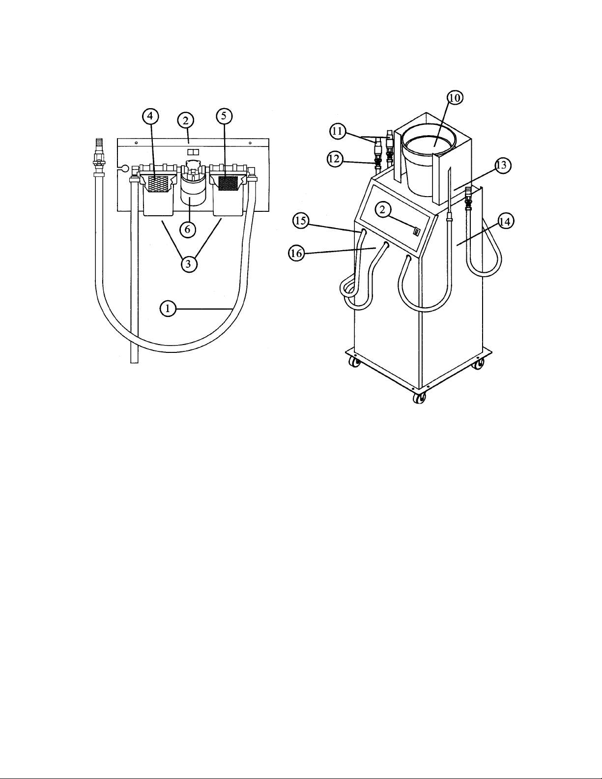
Coolant Service Center/Recycler
Parts List
Item Description Part Number
1 Filter Outlet Hose Assembly 070-80008-00
2 On/Off Switch 070-80009-00
3 Filter Housing 070-80010-00
4 & 5 20 pc Filter Pack 070-80007-00
(10) 25 & (10) 5 Micron
6 Filter Pump & Motor Assembly 070-80013-00
7* pH Measuring Sticks 070-80012-00
8* CSC10R Reinhibitor 070-80006-00
9* Filter Housing Wrench 070-80014-00
10 Fill Bucket 070-80015-00
11 Step Adapter 070-80016-00
12 Ball Valve 070-80017-00
13 Plastic Wand 070-80018-00
14 RED Pump Hose 070-80019-00
15 BLACK Drain Hose 070-80020-00
16 GREEN Fill Hose 070-80021-00
18* Pump Impeller Kit 070-80022-00
19* Evacuation Pump & Motor Assembly 070-80013-00
* Items Not Shown on Drawing
- 14 -
Page 16

FREEZE POINT ADJUSTMENT CHART
STEP 1 - CHECK FREEZE POINT OF PROCESSES COOLANT
STEP 2 - DETERMINE NUMBER OF GALLONS OF PROCESSED
COOLANT IN CLEAN COOLANT DRUM. THE DRUM HAS
GALLON MARKINGS ON THE SIDE.
0
STEP 3 - ADJUST FREEZE POINT TO -34
QUARTS OF ANTIFREEZE USING THE CHART BELOW.
STEP 4- ADD PROPER AMOUNT OF REINHIBITOR PER
INSTRUCTIONS ON BOTTLE LABEL OR MANUAL.
F BY ADDING REQUIRED
GALLONS OF PROCESSED COOLANT
FREEZE
POINT
-250F 1.8 1.5 2.5 3.5 4.5
0
F1.534.567.5
-20
0
F246810
-15
0
F 2.5 5 7.5 10 12.5
-10
0
F 3.5 7 10.5 13.5 17
-5
3
GALLONS6GALLONS9GALLONS12GALLONS15GALLONS
U
U QUARTS OF ANTIFREEZE TO ADD U
UU
U
UU
RTI TECHNOLOGIES, INC. York, PA 17402
- 15 -
 Loading...