

Page 1

Bench Mounted Lathe
RTI TECHNOLOGIES, INC.
Division of A’Gramkow
York, PA 17402
800-468-2321 (ext. 259)
Manual P/N 035-80470-00
Page 2

Table of Contents
I Introduction ........................................... 1
II Safety............................................... 2
III Checking out the Parts .................................. 3
Figure 1 Standard Accessories .......................... 4
Figure 2 Optional Accessories .......................... 5
IV Initial Set-up .......................................... 6
Figure 3a Tip Holder and Cutting Tip Setup ................ 7
Figure 3b Mounting the Tool Holder ...................... 8
Figure 4 Drive Belt Position and Adjustment ................ 9
V Cutting Brake Rotors .................................. 10
Figure 5 Mounting a Hubless or Composite Rotor with
less than 6.95" inside hat diameter .............. 12
Figure 6 Mounting a Hubless or Composite Rotor with
Larger than 6.95" inside hat diamet er ............ 13
Figure 7 Mounting a Rotor with hub ..................... 14
VI Cutting Drums........................................ 15
VII Locking the Tool Slide ................................. 15
Figure 8 Mounting Hubless Drums ...................... 16
Figure 9 Mounting Drums with Hubs ..................... 17
Figure 10 Setup of Drum Cutting Tool ................... 18
Figure 11 Tool Slide Lock............................. 19
VIII Changing Spindle Speed ............................... 20
IX Adjusting Chain....................................... 20
X Changing Cutting Tips ................................. 20
XI General Maintenance .................................. 20
XII Technical Support ..................................... 20
Page 3

I. Introduction
Thank you for your purchase of a BRC500/550 brake lathe. Congratulations on your choice! The
BRC500/550 is designed to outperfor m every other com par able brake lathe in all respects.
The BRC550 is just like the BRC500 except that the BRC 550 comes with an exclusive RTI feature
that we call “offset step feed”. The offset step feed can be turne d on or off. When off, the BRC550
operates in the same way as the BRC500. When the offset step feed is on, the feed for the brake
disc cutting tools is turned on and off intermittently so as to create a non-directional finish
automatically. Non-directional finish is normal ly only an issue when cutting at high feed rates. The
BRC500 when set at low feed rates for a finish cut will produce a surface finish so good, that no
directional pattern is noticed.
The BRC500 was designed as a completely new product, with the new re quirements for brake disc
turning for moder n late m odel automobiles and lig ht truck s in m ind. T he BR C 500 is designed to
minimi ze run out. In fact “near zero” run out can be easily achieved. Minimizing brake disc run o ut
is an important aspect of modern brake service. Additionally, the BRC500 is designed to allow you
to produce a surface finish that is superior to that on most new rotors. The BRC500 can
consist ently produce bett er than 35 m icro inches where most ot her lathes can do no bet ter than
40 or 50 micro inches. This smoot h surface finish is required for fast br eak in and maximum
stopping power. Brake lathes designed in the past (even many that are sold today) cannot in most
cases match the results of the BRC500.
Another major design innovation with the BRC500 is the simplicit y of the set-up using a new
concept in adaptor and arbor design. You will note that t he BRC500 uses a special “hub surface
locator” along with a special high mass “outboard supporting cone” and a special 1 3/16" (30 mm)
“big arbor” . With this one basic standard set-up, composite and hubless rotors with a hat diameter
of less than 6.95 inches (176 mm) can be turned--this set-up and the big arbor with 40% more
strength than competitor’s arbors is one of the secrets to achieving near zero run out and a
superior finish. For larger rotors on HD trucks, a larger set of adaptors is required as an option--the
set-up being similar. For hub-type rot ors, a set of bear ing ra ce co nes are supplied as st andard.
Drums are set-up in a manner almost the sam e as with rotors. Chang eover t ime from dr ums to
rotors or from rot or s t o dr um s is less than one minute.
Running the BRC500 is simple. It can be set for one of two spindle speeds. In most cases you will
use the 110 RPM slow speed, but by making a fast belt change, the speed can be increased to 220
RPM to allow an extra superior finish on small passenger car rotors. The BRC500 can be used as
a “single pass-one cut” machine by selecting a feed rate setting of 2.5-3. This is the recommended
technique for drums. However, RTI recommends a “two pass” machining process for rotors, with
a setting of 5-6 f or a r ough “foundation” cut j ust deep enough to clean up the r ot or, and an extra
fine finish cut, with a depth of only 0.001-0.002" (0.025-0.05 mm) per side and a setting for the feed
of 1, taking f ull advantage of the special elect ronics and cutting tool design of the BRC500/550.
This two pass technique will not remove any more material than necessary, and even though it may
take a few minutes longer, it will result in a more perfect rotor in every respect.
The precision machined components of the BRC500/550 are produced by our affiliate, Hunger in
Germany, using the most modern and sophisticated machine tools in the world. For more than 30
years, Hunger has been the leading automotive brake lathe manufacturer in Germany. The
electrical controls are made in the USA, with f inal assembly of the electr ical control component s
and assembly/testing of the com plete lathe done by RTI in the USA.
Page 1
Page 4

II. Safety
Before we go to the next step, some reminders about safety
A. Avoid a major injury because of an unexpected start-up!
The BRC500 comes with a special mushroom type r ed “off/stop” switch. Be sure tha t
this switch is always pushed in when the lathe in not operating. This is particularly
important when mounting rotors or drums on the lathe or when changing the belt/s.
When pushed in, even if someone pushes the green “on/start” button, the lathe will not
start. The “off/stop” switch must be pulled out before the lathe can start.
B. Avoid a major injury from rotating machinery!
The BRC500 has a 1 HP spindle motor with a g reat deal of power and tor q ue. Do not
wear loose c lothi ng that could be entangled in the rotating par ts. Be sure that long hair
is properly secured so that it can not be entangl ed in the r otating parts. Do not place
any part of your body near the r otating part s of the B RC500 when in operation. Alw ays
be aware of the location of the red emergency stop switch so that the lathe can be
stopped immediately.
C. Protect your eyes!
Small metal chips will fly off from the rotor or drum during machining. Be sure to wear
your safety glasses at all times when the BRC500 i s in operation. Use the same safety
glasses that you are required to use when grinding metal.
D. Avoid possible electrical shock or unsafe operation!
Like any elec t rical appliance, nev er operate the BR C 500 when it is wet, or w hen y ou
are standing in water. Always unplug the BRC500 when servicing t h e electrical parts
of the BRC500. Be sure the receptacle for t he electrical plug is a three prong grounded
type, that it is the correct voltage for the BRC500/550 (110V, 60Hz in the North
America), that it is protected by a fuse or circui t breaker with the correct rating (15 Amp
maximum in North America), and that it is protected with a Ground Fault Interrupter
(GFI) dev ice. The BRC500/550 is protected by a fuse. Replace this fuse only with one
that is the same rated capacity.
E. Avoid all fire hazards!
The BRC500 is equipped with a special thermal overload device for your safety.
However, if for any reason the lathe spindle is jammed or locked up and stops
suddenly, be sure to turn the power off and unplug the l athe immediately, before fix ing
the cause of the problem.
Page 2
Page 5

III. Checking out the parts
A. The BRC500/550 lathe comes standard with:
Main lathe housing assembly
Foundation mounting bolts (Qty=4)
30 mm diameter Arbor with four Allen head cap scr ews
Standard Adaptors (See Figure 1)
Large open end wrench for Arbor nut
T-Handle wrench for square locking screws on cutting tip holders and bars
Small Allen Wr ench for locking belt pulley
Hand-held mini-lubrication pump for slideway nipples
15 mm (1/2") Positive Rake disc cutting tip holders (Qty=2, one right & one left )
Positive Rake Cutting Tips (Qty=10)
Drum cutter bar with Tip Holder
Vibration dampening rubber ring for discs
Vibration dampening belt for dr ums
Cleaning brush
B. The optional bench comes with:
Top Panel
End Panels (Qty=2)
Mid Panels (Qty=2)
Nuts and bolts for assembly
Assortment of studs f or st or age of accessories
C. The optional merchandising and lig ht kit comes with:
Uprights (Qty=2)
Peg type back board
Sign
Flourescent light
Chains for hanging light (Qty=2)
Nuts and bolts for assembly
D. The optional HD truck adaptor kit includes (See Figure 2):
Hub Surface Locator for rotors with inside hat diameter greater t han 6.95" (176 mm)
Outboard Supporting Cone to mat ch t he large Hub Surface Locator
The 3-5/8" to 4-7/8" ( 92- 123m m ) Inboard Centering Cone should be ordered separately.
Call RTI or your distributor for other accessories that are available.
Page 3
Page 6
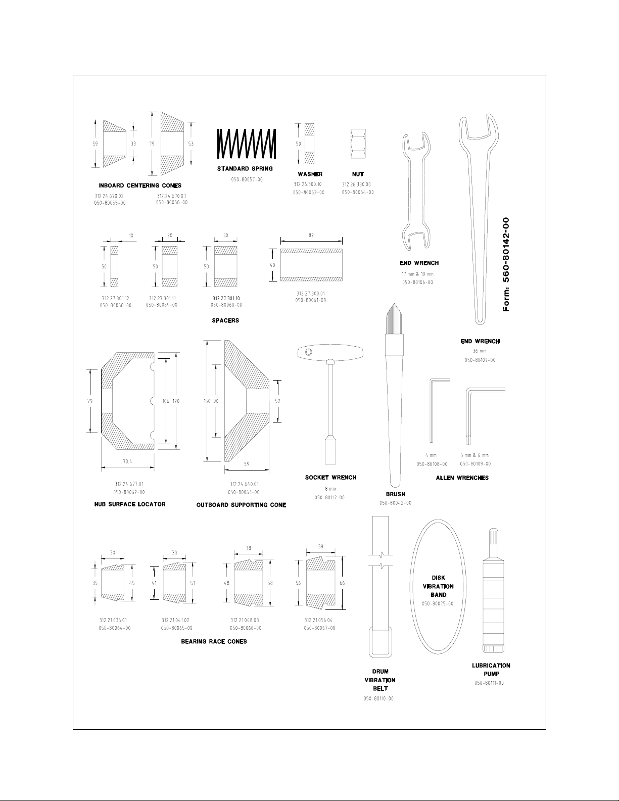
Figure 1 Standard Accessories
Page 4
Page 7
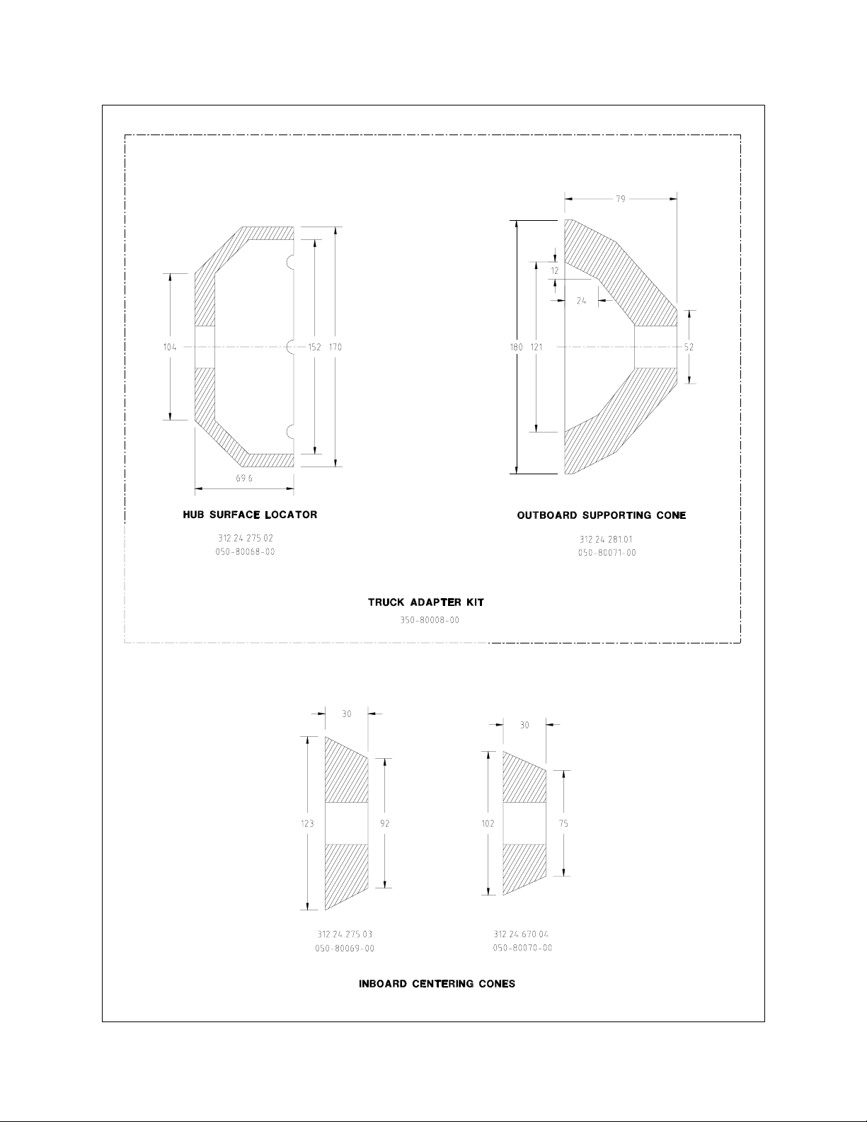
Figure 2 Optional Accessories
Page 5
Page 8

IV. Initial Set-Up
A. Cleaning. The BRC500/550 is shipped with a rust preventative material on the unpainted
surfaces. Clean these surfaces, removing the rust preventative with a cleaning solvent. Do not use
a solvent that will dissolve the paint. Do not remove grease from the Feed Screws. After cleaning,
apply a light machine tool oil to lubricate the cleaned surfaces. You will need to move the tool slide
outward to its maximum extension and move it side to side with the two hand wheels. (Be sure the
black feed engagemen t k nobs in t he hand wheel hubs are pulled out.) Then, using the supplied
hand-held mini-lubrication pump, inject a small amount of oil in the slideway nipples. (This cleaning
and lubrication should be done periodically as part of normal ma int enance. )
B. Mounting. The BRC500/550 can be lifted using the eyebolt supplied, installed in the front of the
main lathe casting. (Caution, the tool slide should be as close to the main lathe housing as
possible. If not the unit may tend t o tip over when lifting or moving be for e it is mounted on t he
bench.) The BRC500/550 can be mounted to a heavy duty work bench. The (4) special bolts are
suppli ed with the lathe and are mounted through the bench to the bottom surface of the main lathe
casting. An optional heavy duty steel bench designed for t he BRC500/ 550 is available from RTI .
In addition, an optional merchandising kit, with a backboard and 46" flourescent light is also
available from RTI.
C. Installing the Arbor. T he precision arbor flange is mounted to the spindle flange using (4)
special Allen head cap screws. Be sure the arbor flange and t he spindle flange are clean. The
arbor flange mounting screws must be tightened securely to 30-35 lb-feet of torque in a cross
sequence using a 6 mm Allen W rench. A t orque wrenc h i s r ecommended. T he threads for the
arbor flange bolts are right hand and those on the end of the arbor are left hand, so you can use
the arbor nut to hold the arbor with the arbor nut wrench supplied when tightening ar bor flange
mounting screws. Clean the threads of the bolts and the spindle flange, then use blue Loctite on
the threads of the screws to insure they remain tight. They should be checked periodically as part
of normal maintenance. If t he cap screws are not tig ht, vibr a t i on an d a poor sur f ace f inish when
turning drums and r ot ors will result. O ne important aspect of the BRC500/550' s precision is the
correct torque of t he ar bor flange mounting screws.
D. Installing t he Cutting Tool Holders. The BRC500/550 comes with an extra str ong and rigid
cutting tool holder assembly. The cylindrical bar, with the flat machined por tion on top, is to be
inserted into one of the large cylinder bores of the cross slide. The inner bore, closest to the main
housing is for extra small rotors. The ou ter bore is for medium and large rotors. Use the outer bore
for most rotors. Clean all unpainted surfaces on t he bar, inside the bores, and on t he tool holder
arms as well as th e tip hol ders and tips to be installed, removing the rust preventative with a
cleaning solvent. Do not use a solvent that will dissolve t he paint on t he painted surfaces. After
cleaning, apply a light machine tool oil to lubricate the cleaned surfaces. After inserting the bar into
the bore so that the bar is approximately flush with the right side of the bore, and the tool holders
are horizontal or pointing slightly down, tight en the small square lock nuts using the T- Handle
wrench (See Figure 3a). Then, install the t ips on the tip holders with the screws provided. (With
positive rake tips, be s ure the tips are right side up and the back face is flat against the tip holder
machined back surface.) Then install the tip holders o n the tool holder arms, tightening the square
lock nuts with the T-Handle wrench. (See Figure 3b)T his set up is now alm ost ready for cutting
brake rotors/discs. The drum set up will be discussed later. Clean all other accessories, including
the drum cutting tool holder and apply a light oil.
E. Remove the black plastic transmission cover and position the belt on the slow speed (110 RPM)
setting. (See Figure 4) Re- inst all t he transmission cover.
Page 6
Page 9

Figure 3a Tip holder and cutting t ip set - up for rotors (positive rake)
Page 7
Page 10

Figure 3b Mounting the Tool Holder
Page 8
Page 11

Figure 4 Drive Belt position and adjustment .
Page 9
Page 12

V. Cutting Brake Rotors/Discs
A. Hubless Rotors. Figure 5 shows the most common adaptor set-up. Inst all the Hub Surface
Locator onto the arbor with the smallest diameter flat surface against the arbor flange. The largest
diamete r flat surface with the slots now simulates the flat surface of the hub of the vehicle. (Unlike
other lathes, on the BRC500/550, special care has been taken to grind both surfaces of the Hub
Surface Locator so that there is near zero run out of the larg e diam eter f lat surf ace. ) Now install
the Spring, Inboard Supporting Cone and brake rotor/disc as shown. The Inboard Supporting Cone
will be pushed toward the rotor by the spring and will keep the rotor centered. Install the Outboard
Supporting Cone and clamp the total assembly by installing spacers as needed and tightening the
left hand thread of t he arbor nut. Be sur e to spacers extend slightly past the arbor shoulder, use
the special washer, and do not over-tighten the nut. Figure 5 shows the set up using the standard
adaptors for brake rotors with an inside hat diameter less than 6.95" (176 mm). Figure 6 shows
the same set up using the optional HD truck adaptors for larger rotors. The standard adaptors can
be used for larger rotor s, but in some rare cases the opt ional adaptors are needed to minimize
vibration on extra large rotors with extra thin hat web sections.
B. Composite Rotors. One revolutionary aspect of the special adaptors designed for the
BRC500/550 is that these adaptors work very well for composite type rotors as well. No special
care or set up for composite rotors is required. The secret is the fact th at the rotor hat web section
is clamped tightly with full metal to metal contact between the Hub Surface Locator, rotors hat web,
and the Outboard Supporting Cone.
C. Vibration Dampening. The B RC500/550 comes with a Vibration Dampener rubber ring. This
should be installed onto the largest outside diameter of the rotor. Ther e are m any other types of
vibrat ion dampener types, including a device using two (2) rubbing blocks. On any rotor larger than
10" (255 mm) some type of vibration dampening devi c e is recommended to av oid ex cessive hi gh
pitched noise or vibration when machining the rotor.
D. Rotor and Hub Assembly. See Figure 7 f or the set up fo r ro tor s with the hub installed. Here
instead of clamping to the ro t or hat web section, the clamping is to the bearing races in the hub.
To insure that there is no abnormal run out, first be sure that the bearing races are in good
condition with no pitting and then after first tightening the arbor nut, loosen it very slightly and retighten.
E. Check Spindle/Arbor/Rotor Rot ation. Plug the power cord into a receptacle with the correct
power rating and safety features as descr ibed in t he Safety section of this manual.
Be sure all items are clear of the spindle/ arbor/rotor assembly, and be sure that t he black knobs
in the center of both
the green start button. Check for proper rotation. Stop the spindle/arbor/rotor’s rotation by pushing
the red mushroom stop switch.
F. Setting up for cutting. With the black knob inside the hand wheel pulled out, manually turn the
wheel, moving the cutting tool slide and th e cu tt in g tips t o a position almost t ouching the r otor’s
largest diameter. Note that there are two locking levers, one on the top of each cutting tool holder
along with a graduated adjusting knob to the left. By locking down one lever, with the other
loosened, turning the adjusting knob will move the tool holder with the lever loosened. Move each
tool holder so that the cutting tips are ve ry close, but not touching each side of the rotor--then move
the tool slide and cutting tips so that they are approx imately 1/4" (6 mm) inside the rotor’s largest
diameter braking surface.
hand wheels are pulled outward. The start the lathe momentarily by pushing
Page 10
Page 13

G. Initial surface cut. W ith the cutting tips appr oximately 1/4" (6 mm) in side th e rotor’s largest
diameter braking surface, with each tip close but not touching the rotor’s surfaces, start the lathe
by pushing the green start switch. With the rotor now rotating, by loc king down one lever of the two
tool holder locking levers, with the other loosened, turn the adjusting knob to move the tool holder
with the lever loosened until the cutting tip just “kisses” the rotor surface. This can be determined
by sound and sight. Lock down the lever and loosen the other tool holder lever, moving the cutting
tip with the adjusting knob similarly until the second cutting tip also just “kisses” the rotor surface.
Now, manually move the tool slide outward by turning the hand wheel very slowly . This will remove
any “ridge” on the outside edge of the rotor. (If the ridge is particularly large, this may require that
the cutting tips be moved outward and then inward with several passes. In this case, after removing
the ridge, stop the lathe rot at ion and r epeat the initial surface cut set up.)
H. Checking rotor surface. Once the in itial surface cut set-up is complete and the ridge is removed,
manually move the tool slide inward by turning the hand wheel very slowly. (If the depth of cut
increases significantly as the cutting tip moves inward, the rotor is warped or tapered. In this case,
stop and move the cutting tool outward away from the rotor surface to compensate.) When both
cuttings tips reach past the smallest diameter of the braking surfaces, stop the manual rotation of
the hand wheel. (Note that it is common for one cutting tip to reach this point before the other. As
long as one tip does not touch the rotor hat, continue until the manual rotation of the hand wheel
until both tools are inside the edge of the braking surfaces on both sides of the rotor. If one tip hits
the rotor hat b ef ore this is accom plished, it will be necessary to slide that cutting tip’s tip holder
back by loosening the two square locking nuts.)
I. Setting Depth of Cut and Speed. Note that the adjusting knob is calibrated with numbered “large”
graduations. These long lines denote 0.004" (0.10 mm) of tool holder and tip movement. The
shorter lines half way in b etween theref or e denote 0. 002" (0. 05 mm ). At this point , t he operator
has the choice of a “one pass” or a “multi- pass” t echnique. In order to per f orm a “one pass” cut ,
the operator must estimate t he depth of cut that will remove run out , taper, and grooves noted
during the rotor surface checked during manual hand wheel rotation, and to determine if that cut
will or will not res ult in the rotor being too thin (Less than manufacturer’s discard thickness.) Since
this is a complex procedure to estimate the exact depth, without cutting more than is needed and
wasting valuable rotor thickness, it is recommended that the a “multi-pass” technique be used. To
perform the first pass of a “multi-pass” technique, move each cutting tip inward 0.004" (0.10 mm)
or one large graduation by unlocking one lever, rotating the adjusting knob, locking that lever and
repeating the procedure for the other tool holder. (Note the total movement of the knob should be
0.008" (0.20 mm) after both tools are moved.) Now rotate the feed control knob to the setting of
“6 = Rough”, set the feed sele ction to “disc=out”, and push the black k nob in the center of the
handwheel inward. The tools will move outward rapidly while cutting. (For a “one-pass” technique
the depth set is as required and the feed control setting is “2-3=medium ”.) If this firs t “ rough cut”
does not cut the entire surface of the rotor and remove all grooves, then move the tool slide inwa rd
manually and repeat the procedure as required. Don’t forget to pull out and then push in the black
knob. Once there is a rough cut surface over the entire rotor surface and all grooves are removed,
now check to see if the rotor is too thin. If another at least another 0.008" (0.20 mm) could be
removed without the rotor being thinner than the discard thickness, then up to 0.004" (0.10 m m)
can be removed (0.002" = 0.05 mm each side) leaving some material for future wear of the rotor.
If so, move the tool slide inward manually and set each tool for a 0.002" (0.05 mm) “finish cut”. Set
the feed control at “1 = Fine”. (For the BRC550 also engage the Offset Step Feed.) This will result
in an extremely smooth surface finish.
Page 11
Page 14

Figure 5 Mounting a Hubless or Composite Rotor with less than 6.95" (176 mm) inside hat diamete r
Page 12
Page 15

Figure 6 Mounting a Hubless or Composite Rotor with larger than 6.95" (176 mm) insid e ha t dia mete r
Page 13
Page 16

Figure 7 Mounting a Brake Rotor with Hub
Page 14
Page 17

VI. Cutting Drums
A. Mounting. Mounting a brake drum on the arbor is similar to mounting a br ake rot or/disc. Se e
Figures 8 and 9. In order to have clearance for the drum, you will first need to loosen the (2) square
locking screws holding the rotor cutting tool holder assembly and either: 1) Remove the entire rotor
cutting tool holder assembly from the tool slide, or 2) Rotate the assembly 180 degrees so the tool
holders point away from the arbor and re-tig hten the locking scr ews. Rotating the assembly is
recommended and will give enough clearance for all but lar ger drums.
B. Install and Position Cutting T ool. Move the tool slide inward manually. Install t he drum cutting
tool bar in the slot of the tool slide. Position the bar so that the cutting tip extends toward the drum,
past the edge of the tool slide as necessar y to cut the ent ire drum surf ace. T hen lock t he bar in
place with the square locking screws. Normal operation is with the large drum cutting tool toward
the drum. (See Fig ur e 10 ) Fo r larg er drums, it may be necessary to reverse the posit ion of the
cutting tool bar, using one of the rotor cutting tool holders installed on the bar as shown.
C. Vibration Dampener. Install t he vibrat ion dam pening belt to minimize noise and vibration.
D. Setting Depth of Cut and Speed. Using the hand wheel on the right side of the lathe, move the
cutting tip inside the drum and position the cut ting tip 1/4" (6 mm) inside the lip of the drum.
Manually remove the rid ge and move the tool manually inward using the same general procedure
as with rotors/discs so as to establish the initial cutting position. The manual “feed” movement of
the cutting tool is with the side handwheel that moves the tool slide side to side. Depth of cut of the
cutting tool is set manually using the handwheel in the front of the lathe that moves the tool slide
in and out. The graduated hub on this handwheel will indicate the precision movement to set the
depth of cut. Once the depth of cut is set as desired, set the feed at “2-2.5=medium”. Set the feed
selector switch to “left to right” and push the black knob in the center of the side handwheel inward
so that the tool slide mov es to the right automatically. The same general procedures as to checking
for discard thick ness of a rotor/ disc apply to the discard diameter of a drum. T he same general
issues of “one-pass” and “multi-pass” cutting also apply. The major difference of operation is simply
that the au to feed for drums is from left to right instead of in to out and the depth of cut is set using
the outer handwheel.
VII. Locking the Tool Slide
In order to ensure the very best precision, the BRC500/550 has the provision to allow the operator
to lock the tool slide during cutting. (See Figure 11) This is more important for cutting rotors where
near zero run out is desired. Therefore the locking provision for the side to side movement of the
tool slide durin g rotor/disc machining is accomplished by tightening the black plastic knob. To lock
the in/out movement of the t ool slide when cutting drums, an Allen type wrench is required. The
tool slide locks push a small aluminum pad against the tool slide guide. D o not over tighten the lock
or the pad may be damaged. Be sure the tool slide lock is only engag ed during t he f inal cut and
is disengaged when the cut is complete!
Page 15
Page 18

Figure 8 Mounting Hubless Drums
Page 16
Page 19

Figure 9 Mounting Drums with Hubs
Page 17
Page 20

Figure 10 Set Up of Drum Cutting Tool
Page 18
Page 21

Figure 11 Tool Slide Lock
Page 19
Page 22

VIII. Changing Spindle Speed
All drum cutting and most rotor cutt ing should be done at 110 RPM or the slow speed setting as
shown in Figure 4. (This 110 RPM is faster than the slow and medium setting of most competitor’s
lathes.) For advanced level operation, cutting rotors with less than 10" (255 mm) the BRC500/550
is designed to allow for an extra fast 220 RPM fast setting. The faster speed will produce a better
surface finish, but tool life will be reduced. To change the belt position and spindle speed, first
loosen the Allen type l oc k sc rew on the pulley arm and then loosen and move the pulley arm stop
adjustment screw to the right. Chang e the belt position, tighten and m ove the pulley arm stop
adjustment screw to the left, locking the pulley arm by finally re-tightening the A llen type lock screw
on the pulley arm. Be sure both the narrow primary belt and the wider se condar y belts are both
tight and do not slip. There should be about 1/16 “ (1 mm) of movement in the belt when
approximately 10 pounds (5 Kg) of force is applied in the middl e of the belt. The belt should not be
too tight. This is evident if more than 20 pounds (10 Kg) of force is required t o deflect the belt or
chain 1/16" (1 mm)
IX. Adjusting Chain
The BRC500/550 uses a special roller chain for the final drive of t he spindle so that the full 1 HP
of the spindle motor can be used, with no vibration and no slippage. This chain may require
adjustment during the life of the lathe. The correct t ension will result in the chain deflecting from
at least 1/16" (1 mm) to a maximum of 1/4" (6 mm) when approximately 10 pounds (5 Kg) of force
is applied to the middle of the chain. Too much play may result in vibration and excess noise. To
adjust the chain, the top center pulley has an eccentric cam. To make the adjustment, the control
box must be removed to gain access to the lock nut for the eccentric cam. Re-check the t ension
of the middle belt.
X. Changing Cutting Tips
RTI’s Positive Rake Cutting Tips have three corners. There is a top and bottom. The tips will only
work when the top is up. When viewed from the side, the top is evident based on the fact that the
taper should from the top edge to the bottom with the top edge protruding more. The cutting tip
edge on each corner is worn and should b e changed when the surface finish no longer meets
requirements or when the corner is chipped or damaged. When one corner is worn, simply loosen
the tip, turn it 120 degress and r e- inst all ( See Figure 3).
XI. General Maintenance
There is no sug gested m aintenance to the BRC500/550 other than: 1) Keep the entire lathe,
especially the slideways, clean, removing cutting chips with the cleaning brus h supplied after each
use; 2) Clean and lube the slideways as noted in the Initial Set Up Section at least once per week;
3) Check belt and chain tension at least once per week; and 4) Lube the two feed screws and drive
chain with a moly based grease, as needed.
XII. Technical Support
For the life of the BRC500/ BRC550, you are entitled to free over the phone t echnical support.
Please call if you have any questions. Our number is 800-486-2321 or 717-840-0678 (Extension
259). If we are not immediately available due to extra heavy phone traffic, we will call you back the
same day . (8 AM to 6 PM ET). We look forward to speaking to you. We are happy to hear from our
customers.
Page 20
 Loading...