

Page 1
Hub Arm Assembly
RTI TECHNOLOGIES, INC.
York, PA 17402
800-468-2321 (ext. 259)
Manual P/N 035-80608-00
Page 2

Table of Contents
1 Introduction ....................................1
2 Safety ........................................2
3 Material List....................................3
4 Mounting of Hub & Centering Plate Storage Bracket ....4
5 Component Storage .............................5
6 Mounting the Cranks on the Centering Plate ..........6
7 Mounting Centering Plate to the Wheel Hub ...........7
8 Preliminary Runout Compensation Adjustment .........8
9 Mounting the Hub Arm ..........................10
10 Mounting the Lathe Head ........................11
11 Attaching the Drive Motor ........................12
12 Connecting Power ..............................13
13 Final Runout Compensation Adjustment .............14
14 Removing Hub Arm Assembly ....................15
BRC35 Lathe + BRC440 Hub Arm = BRC475
BRC40 + BRC440 Hub Arm = BRC480
Page 3

1 Introduction
Thank you for your purchase of a Lathe and Hub Arm Assembly. Congratulations on your
choice! The BRC Lathe and Hub Arm Assembly is designed to outperform every other
comparable hub mounted brake lathe in all respects.
The BRC was designed as a completely new product. The special hub adaption method
designed by RTI for the BRC is brand new and substantially improved.
The BRC is designed to be easy to use. Once the unit is mounted to the hub it operates in
much the same way as a typical bench mounted lathe. Mounting the unit on the hub of the
vehicle requires the axis of the BRC drive b e aligned or compensated to the hub axis of the
vehicl e. The preci sion of this alignment or compensation for the BRC or any other hub mounted
lathe will determine the rotor run out that is finally achieved.
The time to achieve the necessary compensation or alignment of the BRC is minimal. Less
than two minutes per wheel to g et around 0.002 in. (0.050 mm) of run out and only slig htly more
time to achieve “near zero” or less an 0.001 in. (0.025 mm) of run out. The BRC hub plate is
attached to the hub of the vehicle by means of 3, 4, 5 or 7 special cranks and the
compensation is achieved by simpl y lengthening or shortening the length of these cranks using
a dial indicator to determine the correct setti ng. M inimi zi ng brake r otor r un ou t i s an i mp ortant
aspect of modern brake service. Elimination of pedal pulsation issues on whee ls with preloaded wheel bearings requires less than 0.001 in. (0.025 mm) of run out. If the wheels do not
run on pre-loaded wheel bearings, run out of 0.002 in. (0.050 mm) is acceptable.
Running the BRC is simple. It has two spindle speeds and a variable feed rate.
The BRC can be used as a “single pass- one cut” machine. Howev er, RTI recommends a “tw o
pass” machining process with a rough “foundation” cut ju st deep enough to clean up the rotor
and an extra fine finish cut, with a depth of only 0.001 to 0.002 in. ( 0.025 to 0.05 mm) per side,
taking full advantage of the special cutting to ol desig n of the BRC This two pass technique wil l
not remove any more material than necessary, and even though it may take a few minutes
longer, it will result in a more perfect rotor in every respect.
Technical Support
800-468-2321 (Extension 259)
Page 1
Page 4

2 Safety
A. Avoid a major injury because of an unexpected start-up!
Be sure that the BRC i s not plug ged in and supplied with el ectrical power when the lathe in not
operating. This is particularly important when mounting the unit and performing the
compensation adjustments. In addition, the BRC has an Emergency Stop button on the spindle
drive motor.
B. Avoid a major injury from rotating machinery!
The BRC has a spindle motor with a great deal of power and torque. Do not w ear loose clothing
that could be entangled in the rotating parts. Be sur e that long hair i s pr ope rl y secured so that
it can not be entangled in the rotating parts. Do not place any part of your body near the
rotating parts of the BRC when in operation. Always be aware of the location of the Emergency
Stop button so that the lathe can be stopped immediately.
C. Protect your eyes!
Small metal chips fly off the rotor during mach inin g. Be sure to w ear safety glasses at all times
when the BRC is in operation. Use the same safety glasses that are required when grinding
metal.
D. Avoid possible electrical shock or unsafe operation!
Like any electrical appli ance, never operate the BR C when i t is w et , or w he n you ar e standing
in water. Be sure the receptacle for the electrical plug is a three prong grounded type, that it
is the correct voltage for the BRC ( 110V, 60Hz in the North America), that it is pr otected by a
fuse or circuit br eaker w ith the cor rect rati ng (15 Amp max i mum in Nor th America) , and th a t i t
is protected with a Ground Fault Circuit Interrupter (GFCI).
E. Avoid all fire hazards!
If for any reason the lathe spindle is jamm ed or locked up and stops suddenly , be sure to turn
the power off and unplug the lathe immediately, before fixing the cause of the problem.
Page 2
Page 5
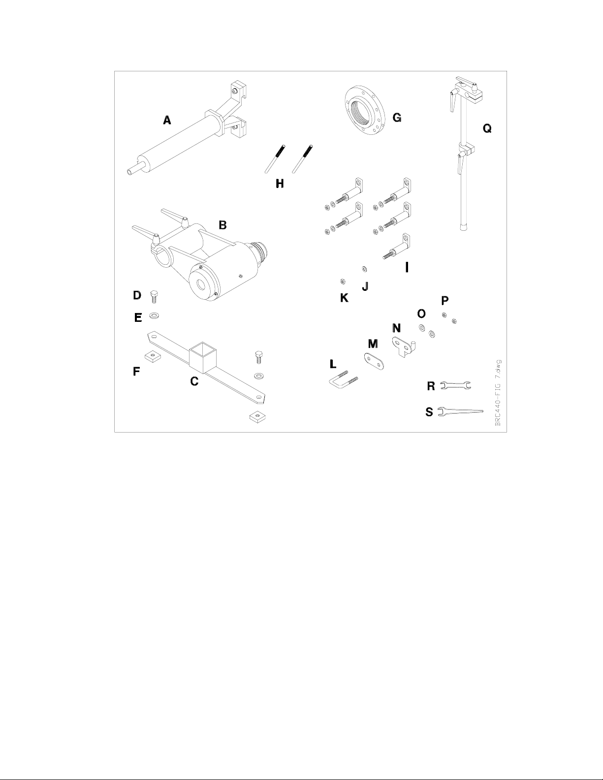
3 Material List
Item Description Quantity
A Arm Assembly 1
B Hub Assembly 1
C Storage Bracket - Hub Arm 1
D Bolt (M10 -1.25 x 15) 2
E Washer 11m m ( ID x 20mm OD) 2
F Square Nut 2
G Centering Plate 1
HTommy Bar 2
I Crank - 90mm (Incl. Adj usting Nut) 5
J Washer (10m m ID x 19mm OD) 5
K Nut (M10 -1.25) 5
LU-Bolt 1
M Rear Plate 1
N Front Plate 1
O Washer (8mm ID x 16mm OD) 2
P Nut (M8 -1.25) 2
Q Adjustable Suppor t Cane 1
R Wrench 17 mm & 19 mm 1
S Wrench 27 mm 1
Page 3
Page 6
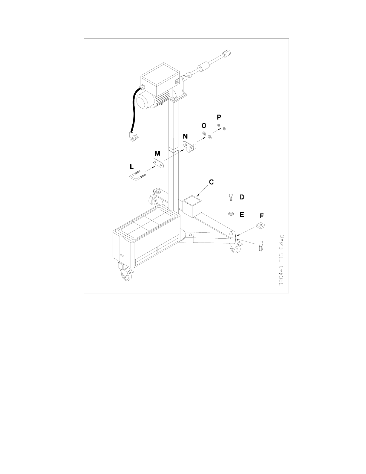
4 Mounting of Hub & Centering Plate Storage Brackets
4.1 Place Square Nut (F) inside each leg and mount the Hub Arm
Storage Bracket (C) using Bo lts and Washers (D-E). Position
the bracket as shown, noting that the ends are cut to match
the angle of each leg. Place plasti c end cap into end of leg s.
4.2 Mount the Centering Plate Bracket (L-M-N-O-P). Position
bracket at the top of the lower column of the Drive S tand. The
hook should face towards the Hub Arm Storage Bracket ( C ) .
Page 4
Page 7

5 Component Storage
5.1 Store Centering Plate with Cranks on hook (A).
5.2 Store Hub Arm Assembly on bracket (B)
5.3 Store Tommy Bars and extra Cranks in box on bracket (C).
Page 5
Page 8

6 Mounting the Cranks on the Centering Plate
6.1 A scribe mark (A) is located on each Crank and l arge nut. Turn t he large
nut onto the Crank as far as possible, finger tight. The scribe mark
should be aligned on the large nut and the barrel of the Crank. Then,
loosen the large nut one full turn, once again ali gning the sc r i be ma r ks.
Do this on all Cranks.
6.2 Numbers (B) are stamped on the Centering Plate next to the holes for
mounting the Cranks. Mount four cranks in the holes numbered 4 for a
four-lug wheel. Mount five cranks in the holes numbered 5 for a five-lug
wheel. Mount three cranks i n th e h ol es number ed 3 for a six -lug w heel.
Insert the Cranks into the appropriate holes, install the washers, and
small nuts. Finger tighten the small nuts.
6.3 Position the legs (C) of all the Cranks so they point in the counterclockwise direction.
Page 6
Page 9

7 Mounting Centering Plate to the Wheel Hub
7.1 Place t he l ar ge holes in the leg s of the Cranks over the wheel l ugs
and install the lug nuts (A) finger tight.
7.2 Tighten the lug nuts to the manufacturer’s recommended wheel
installation torque.
7.3 Place the Vi bration Dampener Rubber Ring (B - supplied with B RC
Lathe Assembly) around the rotor. Other types of vibration
dampeners can also be used. It is always important to prevent
vibration which could cause unsatisfactory surface finish when
cutting the rotor.
Page 7
Page 10

8 Preliminary Runout Compensation Adjustment
8.1 Mount a Dial Indicator (A) rigidly on the hub knuckle assembly. The stylus of the Dial
Indicator must be in contact with surface B as shown. Lig htly tap t he Di al Indi cator to
ensure the needle returns to the same spot to verify it is mounted securely.
8.2 Rotate the Centering Pl ate 360 degr ees several times w hile watching the total swing
of the Dial Indicator needle. Set the mark (C) on the bez el of t he Di al Indi cator to the
MIDDLE of this total swing as shown.
The goal is now to adjust the large and small nuts (D) on the Cranks so that the
TOTAL swing of the needle is 0.004 in. (0.1 mm) or less.
Page 8
Page 11

8 Preliminary Runout Compensation Adjustment (Continued)
8.3 Rotate the Centering Plate until the Dial Indicator needle is at the lar g est number of
the total swing, as shown.
8.4 Nuts on the two cranks are next adjusted to move the needle one-half the distance
between the present reading and the mark on the bezel.
8.4.1 Slightly turn (1/16 rotation or less) small nut A in direction of arrow.
8.4.2 Tighten large nut B by turning in direction of arrow.
8.4.3 Slightly turn (1/16 rotation) large nut D (not visible) in the direction of arrow.
8.4.4 Tighten small nut C by turning in direction of arrow.
8.5 The needle will have moved towards the mark on the bezel, hopefully about one-half
the distance from its starting point. Colored bands on the Cr anks can be used to keep
track of position if the Centering Plate must be turned to aid in adjusting the nuts.
8.6 Repeat Steps 8.3 and 8.4 until the TOTAL swing of the needle during a 360 degr ee
rotation of the Centering Plate is 0.004 in. (0.1 mm) or less. Near zero swing will make
the final adjustments, after the lathe is mounted, much easier.
Page 9
Page 12

9 Mounting the Hub Arm
9.1 Lift the Hub Arm Assembly (A) and carefully insert the threaded end into the
Centering P la te (B). Turn the Centering Plate cl ockwis e as indicated above unti l just
tight. DO NOT use the Tommy Bars to tighten.
9.2 Slide the Adjustable Support Cane (C) onto the Pin (D).The Hub Arm Assembly can
be rotated 360 degrees to allow the best access for cutting the rotor.
9.3 Extend the Adjustable Support Cane using Locking Handle (E) to support the Hub
Arm Assembly.
Page 10
Page 13

10 Mounting the Lathe Head
10.1 Loosen Socket Hex Bolts (A) and slide the Lathe Head into the slots as shown
above. Finger tighten the Socket Hex Bolts.
10.2 Loosen Locking Handles (C) and s lide the Tube (B) to center the Lathe Head on the
Rotor.
10.3 Continue adjusting the Tube (B) and the Lathe Head until the cutting tips are
centered on the Rotor.
10.4 Check that the Lathe Head is slid in towards the cen t e r of the R o tor far enough so
the cutting tips will reach the inner diameter of the rotor surface to be cut.
10.5 Tighten both Socket Hex Bolts (A) and both Locking Handles (C).
Page 11
Page 14

11 Attaching the Driv e Motor
Note: The above shows a cut- awa y of the Hub Arm Assembly to illustrate the connection
between the Drive Motor Shaft and the Pin and Ball in the Hub Arm Assembly.
11.1 Adjust the Drive Motor Stand so the Motor Shaft (A) is aligned with the hol e in the
Hub Arm Assembly.
11.2 Slide the Shaft (A) of the Drive Motor into the Hub Arm Assembly. It may be
necessary to turn the shaft to align the slot in the end fitting with the pin (B) in the
Hub Arm Assembly.
11.3 Push the Drive Motor Shaft into the Hub Arm Assembly until the Ball (C) is felt
snapping into the indent in the fitting on the end of the shaft.
Page 12
Page 15

12 Connecting Power
Note: The above shows the completed set-up of the Hub Ar m Assembly, Lathe Head, and
Drive Motor.
12.1 Push in the Emergency Stop Button on the Drive Motor Control Box.
12.2 Connect the Power Cord (A) to an appropriately grounded power source.
12.3 Connect the Coiled Cord (B) from the socket on the side of the Drive Motor Control
to the socket on top of the Lathe Head.
Page 13
Page 16

13 Final Runout Compensation Adjustment
13.1 Mount a Dial Indicator (A) rigidly on the hub knuckle assembly. The stylus of the
Dial Indicator must be in contact with surface B as shown. Lightly tap the Dial
Indicator to ensure the needle returns to the same spot to verify it is mounted
securely.
13.2 Manually rotate the rotor several revolutions and observe the total runout as
indicated on the Dial Indicator.
13.3 Adjust the large and smal l nuts (C) as described in Section 8 until the TOTAL swing
of the needle is as close to 0.002 in (0.050 mm) as possible.
Refer to the BRC Lathe Operation Manual for instructions on turning rotors.
Page 14
Page 17

14 Removing Hub Arm Assembly
14.1 Insert Tommy Bars (A) as shown above.
14.2 Rotate Tommy Bars as shown to release Hub Arm Assembly from the Centering
Plate.
Page 15
 Loading...