

Page 1

OPERATION
MANUAL
RTI
BRC40
ON-THE-CAR
BRAKE LATHE
RTI TECHNOLOGIES, INC.
4075 East Market Street
York, PA 17402
Manual P/N 035-80588-00
September 1998
Page 2

BRAKE LATHE
BRC40
CONGRATULATIONS... You have purchased one of the finest lathes for on-the-
car machining of brake rotors available at any price.
GREAT RESULTS WITH THE BRC40 ARE AHEAD...
O New, smaller size gives easy access to rear wheel rotors.
O Light weight makes mounting easy.
O Fast to set up and simple to operate.
O Professional, high quality on-the-car brake rotor turning with "total
alignment" every time.
O Uses two reference points - hub axis and caliper mount geometry. Brake
pads will now be perfectly aligned with the rotor.
O Components have maximum flexibility of assembly to allow
customization for individual preferences during setup.
O Integral, high strength storage container keeps accessory items in one
convenient location; no more hunting for tools.
O Mobile stand features a broad range of adjustment; turn rotors while the
car sits on floor jacks or on a hydraulic lift.
RTI
RTI
RTIRTI
TECHNOLOGIES, INC.
TECHNOLOGIES, INC. Page 1
TECHNOLOGIES, INC.TECHNOLOGIES, INC.
Page 3

CONTENTS
Warranty ...................................... Page 3
Lathe & Accessories ............................. Page 4
Drive Stand & Motor............................. Page 6
Main Features .................................. Page 8
Mounting the Lathe .............................. Page 10
Attaching the Drive Motor ........................ Page 12
Control Devices................................. Page 13
Turning a Rotor ................................. Page 14
Slideway Adjustment ............................ Page 17
Summary ...................................... Page 18
WARNING
The Wheel Connection Shaft is connected to the Motor Shaft
with a Universal Coupling.
The Collar provided on the Connecting Shaft must be slid
over the Universal Coupling when not in use.
Serious injury may result if power is applied to the Motor
while the Wheel Connection Shaft is hanging loose.
Page 2 RTI
RTI
RTIRTI
TECHNOLOGIES, INC.
TECHNOLOGIES, INC.
TECHNOLOGIES, INC.TECHNOLOGIES, INC.
Page 4

WARRANTY
Fill out and return the Warranty Card within 90 days to activate warranty and free lifetime
technical support.
WARRANTY... The BRC40 is warranted to be free of defects in workmanship and
materials for a period of one year from date of purchase by original
purchaser.
If the product fails within this period, it will be repaired or replaced at the
manufacturer's option, provided (1) factory authorization has been issued
and (2) the product is submitted with proof of purchase.
Liability under this warranty is expressly limited to repairing or replacing
the product or parts thereof.
This warranty does not apply to product or parts broken due to accident,
overload, abuse, tampering, or alteration.
If this warranty does not apply, the retail purchaser shall pay all costs for
labor, material, and transportation.
FOR SERVICE OR TECHNICAL ASSISTANCE
717-840-0678 (Extension 259)
FAX 717-755-8304
RTI
RTI
RTIRTI
TECHNOLOGIES, INC.
TECHNOLOGIES, INC. Page 3
TECHNOLOGIES, INC.TECHNOLOGIES, INC.
Page 5

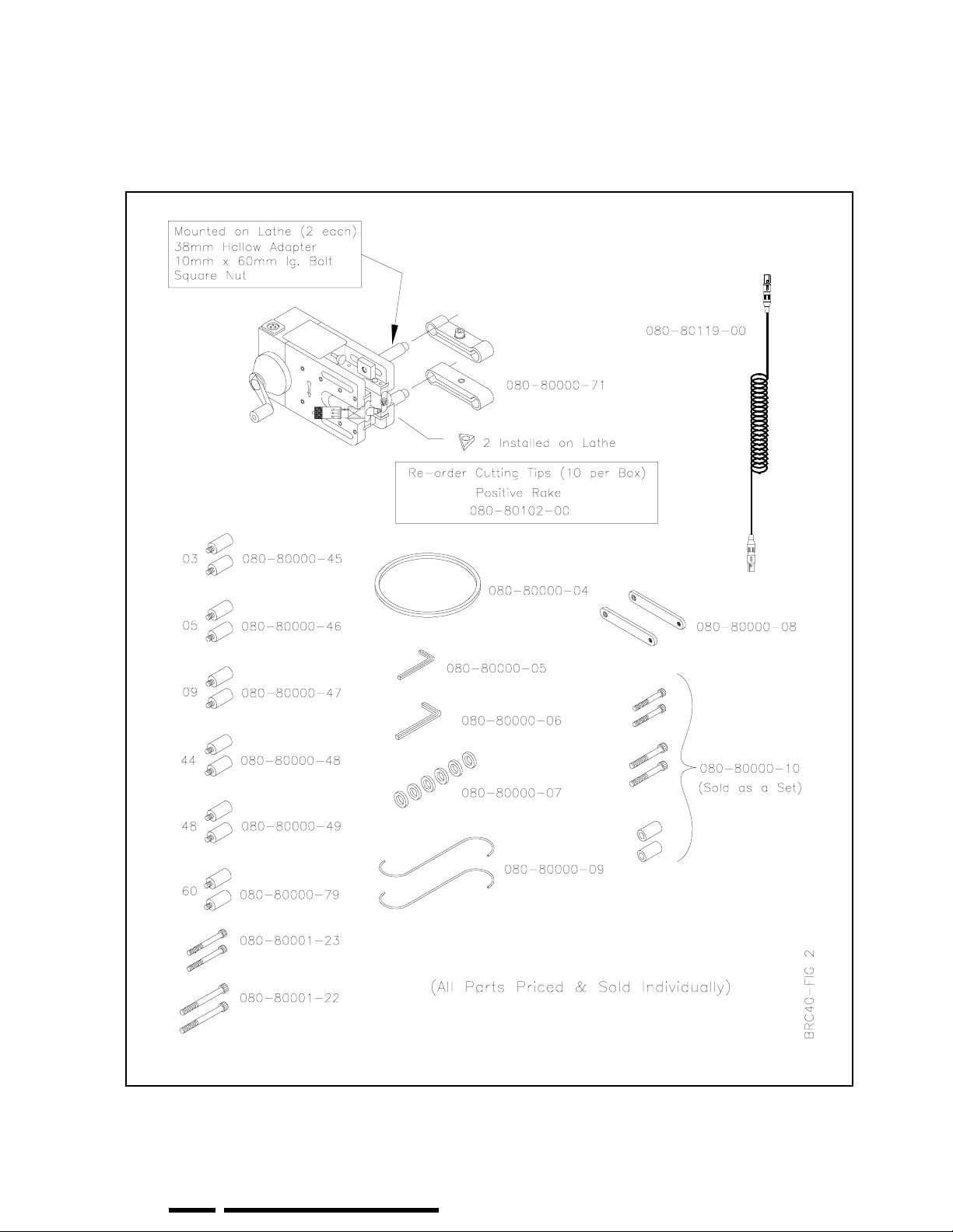
LATHE & ACCESSORIES
BRC40
RTI
Part No.
080-80000-71 Bracket Twin Cylinder (80mm) 2
080-80000-04 Band Silencer 1
080-80000-05 Wrench Hex Key (6mm) 1
080-80000-06 Wrench Hex Key (8mm) 1
080-80000-07 Spacer Mounting 6
080-80000-08 Bar Threaded 2
080-80000-09 Hook “S” Shaped 2
Adapter Hollow (48mm lg.) 2
080-80000-10 Bolt 8mm x 1.25 (70mm lg.) 2
Bolt 10mm x 1.50 (70mm lg.) 2
080-80001-22 Bolt 10mm x 1.50 (90mm lg.) 2
080-80001-23 Bolt 10mm x 1.50 (80mm lg.) 2
080-80000-45 Threaded Adapter 03 (M10 x 1.25) 2
Description Qty
080-80000-46 Threaded Adapter 05 (M10 x 1.50) 2
080-80000-47 Threaded Adapter 09 (M12 x 1.50) 2
080-80000-48 Threaded Adapter 44 (M11 x 1.50) 2
080-80000-49 Threaded Adapter 48 (M9 x 1.25) 2
080-80000-79 Threaded Adapter 60 (M14 x 2.00) 2
080-80119-00 Cord 12 Volt Coiled - 2 Conductor w/ Ground 1
Refer to next page for illustration of above components.
Page 4 RTI
RTI
RTIRTI
TECHNOLOGIES, INC.
TECHNOLOGIES, INC.
TECHNOLOGIES, INC.TECHNOLOGIES, INC.
Page 6
LATHE & ACCESSORIES
BRC40
RTI
RTI
RTIRTI
TECHNOLOGIES, INC.
TECHNOLOGIES, INC. Page 5
TECHNOLOGIES, INC.TECHNOLOGIES, INC.
Page 7

DRIVE STAND & MOTOR
BRC40
RTI
Part No.
Motor Gear Drive (Complete Assembly) Voltage: 110 or 220 VAC
110 volt unit has been tested and approved for 100 volt operation in
Japan
080-80130-00 Power Cord (110 Volt) 1
080-80002-00 Motor Mount 1
080-80002-01 Inner Column 1
080-80002-02 Outer Column 1
080-80003-03 Base 1
080-80003-01 Short Leg 2
080-80003-02 Long Leg 1
080-80000-21 Swivel Caster 3
080-80002-08 Locking Handle 1
080-80000-23 Accessory Box Support 1
080-80000-24 Bolt M6 x 1mm x 35mm Lg. 4
Description Qty
1
080-80000-25 Bolt M8 x 1.25mm x 60mm Lg. 3
080-80002-05 Bolt M10 x 1.50mm x 15mm Lg. 3
080-80003-04 Bolt Allen Socket Head M10 x 1.50mm x 25mm Lg. 3
080-80003-06 Plastic Cap 3
080-80000-29 Washer M6 8
080-80000-30 Washer M8 6
080-80000-31 Washer M10 4
080-80000-32 Nut M6 x 1.00mm 4
080-80000-33 Nut M8 x 1.25mm 3
080-80000-34 Nut M10 x 1.50mm 1
080-80002-07 Nut Square M10 x 1.50mm 6
Refer to next page for illustration of above components.
Page 6 RTI
RTI
RTIRTI
TECHNOLOGIES, INC.
TECHNOLOGIES, INC.
TECHNOLOGIES, INC.TECHNOLOGIES, INC.
Page 8

DRIVE STAND & MOTOR
BRC40
RTI
RTI
RTIRTI
TECHNOLOGIES, INC.
TECHNOLOGIES, INC. Page 7
TECHNOLOGIES, INC.TECHNOLOGIES, INC.
Page 9

MAIN FEATURES
BRC40
Page 8 RTI
RTI
RTIRTI
TECHNOLOGIES, INC.
TECHNOLOGIES, INC.
TECHNOLOGIES, INC.TECHNOLOGIES, INC.
Page 10

CAUTION
Check for any end-play in the wheel
bearing before mounting the BRC40 Brake
Lathe.
A loose wheel bearing may cause a poor
surface finish.
If bearing play is adjustable, tighten nuts
slightly before machining, and then readjust to factory specifications afterward.
If there is play in a non-adjustable bearing,
it should be replaced before machining the
rotor.
Most non-adjustable bearings are doublerow ball bearings that require pre-load.
Tapered roller bearings found on the front
of most rear wheel drive vehicles are
designed to operate with end-play.
RTI
RTI
RTIRTI
TECHNOLOGIES, INC.
TECHNOLOGIES, INC. Page 9
TECHNOLOGIES, INC.TECHNOLOGIES, INC.
Page 11

MOUNTING THE LATHE
1. Place automobile in NEUTRAL with
parking brake OFF and raise on lift.
Start on passenger side and remove
wheel nuts and wheel.
2. Place Spacers on wheel studs as
shown in Figure 1. Replace and
tighten nuts to manufacturer’s
specification using torque wrench.
3. Remove the brake caliper and hang
it out of the way using an S-Hook.
4. Remove all rust and dirt from the
brake caliper bolt area. Failure to
clean these surfaces will result in
unsatisfactory machining.
5. Select Threaded Adapters with
threads matching brake caliper
mounting bolts.
Insert and tighten Threaded Adapters
in the brake caliper bolt mounting
holes.
Some caliper mounting holes are not
threaded. In these cases, use Hollow
Adapters, Threaded Bars, and Bolts.
Refer to Figure 2.
Some caliper mountings may require
special adapters included in the
Deluxe Adapter Kit.
Figure 1 Mounting of Spacers & Wheel Nuts
Figure 2 Mounting of Threaded or Hollow Adapters
Page 10 RTI
RTI
RTIRTI
TECHNOLOGIES, INC.
TECHNOLOGIES, INC.
TECHNOLOGIES, INC.TECHNOLOGIES, INC.
Page 12

MOUNTING THE LATHE
6. Place Twin Cylinder Mounting
Brackets on each of the Adapters
mounted in the preceding step.
Do not tighten the Allen Socket
Bolts in the Mounting Brackets.
7. Hang the Lathe on the lower Twin
Cylinder Mounting Bracket as
shown in Figure 3.
Figure 3 Hang the Lathe
8. Swing the Lathe upwards and
slide the top Twin Cylinder
Mounting Bracket onto the Lathe
mounting bracket. See Figure 4.
9. Position the Lathe so that the
Lathe centerline is slightly below
the center of the wheel hub and
the brake rotor is centered
between the side plates of the
Lathe. Refer to Figure 5.
10. Tighten Allen Socket Bolts in both
Twin Cylinder Mounting
Brackets.
Figure 4 Mounting the Lathe
Figure 5 Positioning the Lathe
RTI
RTI
RTIRTI
TECHNOLOGIES, INC.
TECHNOLOGIES, INC. Page 11
TECHNOLOGIES, INC.TECHNOLOGIES, INC.
Page 13

ATTACHING THE DRIVE MOTOR
1. Tighten Wheel Nuts on all but two
studs. Attach the Wheel Drive
Brackets, with Spacers, to the two
vacant wheel studs as shown in
Figure 6. Leave the two wheel
nuts slightly loose.
2. Slide the sleeve on the connecting
shaft of the Drive Motor away
from the universal coupling so the
shaft is free to articulate.
3. Position the Drive Motor Stand
and connect the Wheel Drive
Brackets to the end of the Drive
Motor Shaft.
4. Tighten the wheel nuts so the
Wheel Drive Brackets are on the
centerline of the wheel hub.
Figure 6 Mounting the Wheel Drive Brackets
5. Carefully adjust the Drive Motor
Stand so the shaft aligns with the
axis of rotation of the wheel.
Refer to Figure 7 for proper setup
and alignment.
6. Set the locks on the Drive Motor
Stand casters. Check that adjusting
handles on the stand are tight.
7. Slide the vinyl cover over the
Wheel Drive Brackets.
This cover must remain in place
during operation of the Wheel
Drive Motor.
8. Connect the coiled Power Cable
between the Wheel Drive Motor
and the Lathe.
Figure 7 Aligning the Wheel Drive Motor
Page 12 RTI
RTI
RTIRTI
TECHNOLOGIES, INC.
TECHNOLOGIES, INC.
TECHNOLOGIES, INC.TECHNOLOGIES, INC.
Page 14

CONTROL DEVICES
FEED DIRECTION SWITCH
Direction of travel of the cutting tools is
controlled by a 3-position switch on the
Lathe Control Panel. Pressing the top
activates INFEED (towards the center of
the rotor) and pressing the bottom
activates OUTFEED (away from the
center of the rotor). Between these
positions is the OFF position.
INFEED STOP
This switch (See Item J on Page 8) stops
travel of the cutting tools when moving
towards the center of the rotor during
automatic operation.
POWER ON LIGHT
This light will be on when the lathe is
feeding in or out (Feed Direction Switch
pressed for INFEED or OUTFEED). The
brightness will vary depending on the
setting of the Feed Rate Switch (1 is dim,
9 is brightest).
The light will be OFF if the Infeed Stop is
pushed in all the way.
EMERGENCY STOP
The Emergency Stop Button stops the
Drive Motor and Lathe. Turn and pull
(See arrows on knob) to reset. Some
switches do not require turning.
FEED RATE SWITCH
Rate of travel (feed) of the cutting tools is
controlled by the variable Feed Rate
Switch on the Drive Motor Control Panel
(1 is slow, 9 is fast).
DRIVE MOTOR SWITCH
Figure 8 Lathe Controls
The Drive Motor turns the rotor
clockwise or counter-clockwise in one of
two speeds (1 is slow, 2 is fast). This 5position switch is located on the Drive
Motor Control Panel. The middle position
is OFF.
RTI
RTI
RTIRTI
TECHNOLOGIES, INC.
TECHNOLOGIES, INC. Page 13
TECHNOLOGIES, INC.TECHNOLOGIES, INC.
Figure 9 Drive Motor Controls
Page 15

TURNING A ROTOR
1) Mount the Lathe and attach the
Drive Motor per the instructions in
the preceding section.
The Silencer Band can be
mounted around the outer edge of
the rotor to reduce noise during
machining if desired. This must
be done before mounting the
Lathe.
2) Set the Feed Direction Switch on
the Lathe Control to OFF (middle
position).
3) Set the Drive Motor Switch on the
Drive Motor Control to OFF
(Marked “0").
4) Check that the coiled Power Cable
is connected between the Drive
Motor and the Lathe.
5) Check that the Emergency Stop
Button is reset to ON (if not, turn
and release to reset).
6) Plug the power cord on the Drive
Motor into a 120 vac supply.
7) Turn the Drive Motor Switch
clockwise to number 1. The rotor
should be turning in the direction
shown in Figure 11.
If not, turn the Drive Motor
Switch counter-clockwise to
number 1.
8) Press the Shift Lock Button and
move the AUTO/MAN Shift to
MANUAL.
9) Using the Hand Wheel, move the
cutting tool tips to about ½ in.
(10mm) inward from the outer
edge of the Rotor.
Figure 10 Lathe Controls
Figure 11 Direction of Rotor Rotation
TURNING A ROTOR
Page 14 RTI
RTI
RTIRTI
TECHNOLOGIES, INC.
TECHNOLOGIES, INC.
TECHNOLOGIES, INC.TECHNOLOGIES, INC.
Page 16

10) Use the Cut Depth Micrometer to
move both cutting tool tips towards
the rotor until they just touch the rotor
surface.
11) Turn the hand wheel to manually feed
the cutting tools outward toward the
edge of the rotor to remove any rust
build-up on the outer edge.
12) Manually feed the cutting tools
inward towards the center of the rotor
to a point slightly beyond the contact
surface of the brake pads. Use care as
the depth of cut may vary due to
runout in the surface of the rotor.
13) Push the Auto Infeed Stop button all
the way in. Twisting the knob while
pushing inward makes this step
easier. This sets the point where the
cutting tools will stop during
automatic feed towards the center of
the rotor in the following steps.
Figure 12 Lathe Controls
14) Press the Safety Lock and move the
AUTO/MAN Shift to AUTO.
15) Turn both Cut Depth Micro-meters
clockwise one large division to move
the cutting tool tips into the faces of
the rotor by 0.004 inch (0.1 mm)
Figure 13 illustrates that 0.004 inch is
the distance between two numbers on
the micrometer.
16) Turn the Feed Rate Switch on the
Drive Motor Control to 9 (fast feed).
17) Press the top (OUTFEED) of the
Feed Direction Switch on the lathe.
The lathe cutting tools will
automatically feed outward, making a
rough cut on the rotor.
Figure 13 Cut Depth Micrometer
RTI
RTI
RTIRTI
TECHNOLOGIES, INC.
TECHNOLOGIES, INC. Page 15
TECHNOLOGIES, INC.TECHNOLOGIES, INC.
Page 17

TURNING A ROTOR
18) When the cutting tools have moved
outward beyond the edge of the
rotor, press the bottom (OUTFEED)
of the Feed Direction Switch on the
lathe to place the switch in the OFF
position.
19) Momentarily turn off the Drive
Motor and check the surface of the
rotor. It should have a rough cut
surface across the entire face on both
sides. If not, make another rough cut,
otherwise proceed to the next step
for a finish cut.
20) Turn both Cut Depth Micro-meters
clockwise one small division to
move the cutting tool tips towards
the face of the rotor by 0.002 inch
(0.05 mm) Figure 14 illustrates that
0.002 inch is the distance between
two of the closest marks.
21) Turn the Feed Rate Switch on the
Drive Motor Control to 2 (slow
feed).
22) Press the top (INFEED) of the Feed
Direction Switch on the lathe. The
lathe cutting tools will automatically
feed inward making a finish cut on
the rotor. The cutting tools will
automatically stop at the setting
determined in Step 13 by setting the
Auto Infeed Stop button.
Figure 14 Cut Depth Micrometer
When a satisfactory surface finish has been obtained, press the
Safety Lock and move the AUTO/MAN Shift to MANUAL.
Back the cutting tool tips away from the rotor by turning the Cut
Depth Micrometers counter-clockwise.
Use the handwheel to back the cutting tools to a position beyond
the outer edge of the rotor.
Remove the Lathe and repeat the operation on the other side of
the vehicle.
One rough cut and one finish cut are
normally sufficient for most applications.
If not, repeat rough and/or finish cuts as
required.
Page 16 RTI
RTI
RTIRTI
TECHNOLOGIES, INC.
TECHNOLOGIES, INC.
TECHNOLOGIES, INC.TECHNOLOGIES, INC.
Page 18

SLIDEWAY ADJUSTMENT
Figure 15 Slideway Adjustment
Periodically check the “snugness” of the Tool Holders in the Slideways. When fully extended from the Lathe,
there should be no movement of the Tool Holders when pulled up or pushed down. Unsatisfactory surface finish
on rotors is often an indication that the Slideways need adjustment.
Carefully study Figure 15 to understand the dynamics of adjusting the tension of the Slideways on the Tool
Holders.
1) Loosen the eight smaller “B” screws by approximately 1/16 turn.
2) Loosen the four larger “A” screws by approximately 1/16 turn.
3) Tighten the eight “B” screws evenly to obtain the “snug” feel of the Tool Holders. Check the operation
and feel by manually moving the Tool Holders in and out with the handwheel.
4) Tighten the four “A” screws to lock the setting of the slideways.
RTI
RTI
RTIRTI
TECHNOLOGIES, INC.
TECHNOLOGIES, INC. Page 17
TECHNOLOGIES, INC.TECHNOLOGIES, INC.
Page 19

SUMMARY
The BRC40 will provide many years of dependable brake rotor
machining with proper care and use.
This manual describes basic operating procedures for quick and easy use
of the BRC40.
As with any fine piece of machinery, experienced operators will quickly
discover new and more versatile methods of operation.
The BRC40 can be set up in various configurations for optimum access
to control devices and tool adjustments. No one way is necessarily the
best for all vehicles.
Cutting tool heads can easily be removed and re-mounted for reverse
cutting applications.
The BRC40 operates up-side-down just as well as right-side-up. Just
remember to set the cutting tools slightly below the centerline of the hub
so the rotor turns downward to the cutting tips.
Adaption to special vehicles may require special accessories.
Page 18 RTI
RTI
RTIRTI
TECHNOLOGIES, INC.
TECHNOLOGIES, INC.
TECHNOLOGIES, INC.TECHNOLOGIES, INC.
 Loading...