

Page 1
OPERATION MANUAL
Brake Fluid Exchanger
IMPORTANT:
Test drive
vehicle after
BFX-1
service to verify
proper brake
system
performance.
Manual P/N 035-80997-00 (Rev A)
RTI Technologies, Inc
4075 East Market St.
York, PA 17402
800-468-2321
www.rtitech.com
Page 2

Table of Contents
Component Description .................. 2
Safety Precautions ...................... 3
System Priming ........................ 4
Exchange ............................ 5-8
Empty Used Tank....................... 9
Fill New Tank .......................... 9
Parts Identification ......................10
Flow Diagram & Electrical Schematic........11
EC Declaration of Conformity for Machinery . . 12
IMPORTANT: Test drive vehicle after service to verify proper
brake system performance
Page 1
Page 3
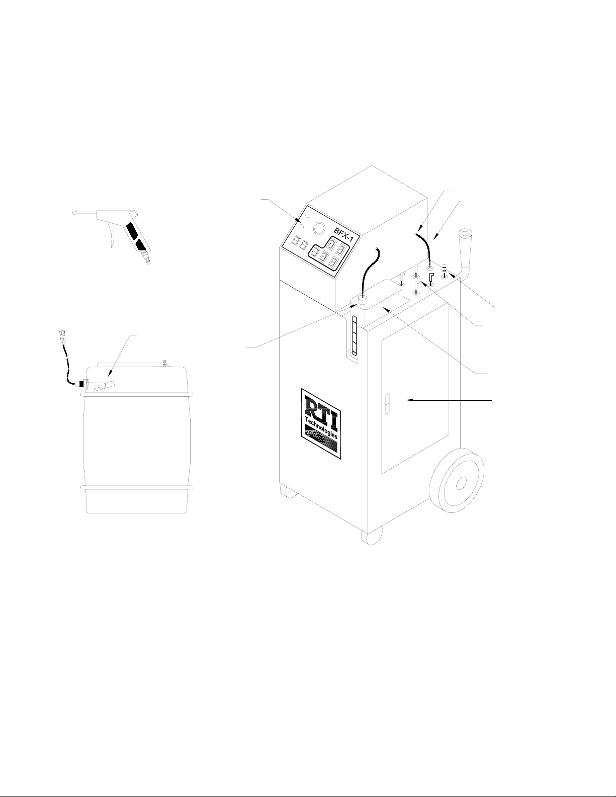
Component Description
Unpack all components and verify quantities per this illustration and adapter list on page 6.
Contact RTI if any items are missing.
Fill Gun
UsedTank
Float
Control Panel
New Tank
Float
Parking Stud
Vacuum Hose
Fill Hose
(4) Bleeder Hoses
New Tank
Hose Storage
Access Door
Used Tank
(Accessed through rear)
IMPORTANT: Test drive vehicle after service to verify proper
brake system performance.
Page 2
Page 4

Safety Precautions
WARNING: Failure to follow these precautions can result in
serious injury or death.
• Read and understand the Operation Manual completely before operating this unit.
• Always wear proper eye and skin protection when operating and maintaining this
equipment.
• Only disassemble or reassemble unit parts when directed by an RTI representative.
• Clean any spills that may occur immediately. Brake fluid is corrosive and is a high slip
hazard.
• Avoid exposure with painted surfaces. Brake fluid is corrosive and will damage the
finish on most painted surfaces. Use of fender covers is recommended.
• Always use vehicle specified brake fluid. Failure to do so may cause brake system
damage. The BFX is designed to use DOT 3 or 4 brake fluid. Use of any other fluid type is
not recommended and may void warranty.
• Comply with local, state and federal regulations for fluid disposal.
• Material Safety Data Sheets (MSDS) must be obtained on all chemicals and placed in a
shop file for reference. Note: MSDS can be found on the RTI web site www.rtitech.com.
• It is important to test drive every vehicle after the service to verify proper brake system
operation. Failure to do so could result in undetected brake system failure.
CAUTION: Failure to follow the precautions as outlined in the Operation Manual can
result in damage to the engine, vehicle or equipment which will not be
supported or covered under warranty.
IMPORTANT: Test drive vehicle after service to verify proper
brake system performance.
Page 3
Page 5

System Priming
Note: The System Priming Procedure is only necessary before the first time use of the
BFX or when changing brake fluid types. Between normal operation cycles, this
procedure will not be necessary.
1. Connect red (positive) clamp on power cable to red (positive) terminal on vehicle battery.
Connect the black (negative) clamp to a good ground. A good ground can be located by
following the negative cable from the battery to where it is connected to the chassis.
Warning: Handle battery connection cable with extreme caution. Batteries generate
explosive gases during normal operation. Working in the vicinity of a leadacid or other automotive battery is dangerous. Wear eye protection. Never
smoke or allow a spark or flame in the vicinity of the battery. Do not connect
the black power clip to the negative post of the battery to avoid a spark.
2. Fill New Tank with desired brake fluid.
3. Connect Fill Gun to Fill Hose.
4. Disconnect coupler on Used Fluid Tank Line and remove the cap.
5. Turn on FILL MASTER CYLINDER switch.
6. Place outlet tip of Fill Gun into the Used Fluid Tank opening and squeeze Fill Gun
trigger.
7. Continue until fluid is moving smoothly through the Fill Gun tip and into the Used Tank
without turbulence (air bubbles) visible in the Fill Hose.
8. Turn off FILL MASTER CYLINDER switch.
9. Disconnect Fill Gun from the Fill Hose.
10. Replace Used Tank cap and connect coupler.
IMPORTANT: Test drive vehicle after service to verify proper
brake system performance.
Page 4
Page 6

Exchange
BEFORE SERVICE: Verify that the Brake System does not have any malfunctions. If the
system is found to be malfunctioning verify that the malfunction will not
interfere with the exchange process. Perform all necessary repairs prior
to exchanging.
1. Verify that the vehicle engine is off.
2. Verify new and used fluid tank levels. Add new fluid or empty used as required.
3. Verify that all Switches and Attention Lights on the BFX control panel are OFF.
4. Connect red (positive) clamp on power cable to red (positive) terminal on vehicle
battery. Connect the black (negative) clamp to a good ground. A good ground can be
located by following the negative cable from the battery to where it is connected to the
chassis.
Warning: Handle battery connection cable with extreme caution. Batteries generate
explosive gases during normal operation. Working in the vicinity of a leadacid or other automotive battery is dangerous. Wear eye protection. Never
smoke or allow a spark or flame in the vicinity of the battery. Do not connect
the black power clip to the negative post of the battery to avoid a spark.
5. Remove master cylinder cover and inspect the master cylinder for damage. Repair any
damage found before continuing.
6. Turn on EMPTY MASTER CYLINDER switch and use the Vacuum Hose to remove all
of the fluid from the master cylinder.
7. Turn off EMPTY MASTER CYLINDER switch when master cylinder is empty and return
Vacuum Hose to Parking Stud.
Note: Failure to park Vacuum Hose on Parking Stud will result in minimum to no
vacuum at bleeder hoses.
8. Connect Fill Gun to Fill Hose. Turn on FILL MASTER CYLINDER switch and squeeze
trigger on Fill Gun to dispense fluid until master cylinder level is at the fill/max mark.
Turn off FILL MASTER CYLINDER and disconnect Fill Gun from the Fill Hose.
Note: To avoid fluid discharge from Fill Gun do not squeeze trigger after disconnecting
from Fill Hose.
9. Connect Master Cylinder Adapter.
IMPORTANT: Test drive vehicle after service to verify proper
brake system performance.
Page 5
Page 7

Exchange continued
A. Identify appropriate adapter for the Master Cylinder being serviced from list below.
B. Seat adapter on the Master Cylinder and tighten snugly.
C. Connect Fill Hose Coupler to the adapter coupler .
BA01 Chrysler & Others
025-88001-00
3 tab, twist on with expandable
O-ring fits most Chrysler
models. 2001+ PT Cruiser,
2002+ Grand Voyager, 1996+
Voyager LE, 1994+ Voyager
SE, Dodge: Power Ram,
Caravan, 2003+ Viper, 2001
Neon Jeep 1996+ Wrangler, 1996+ Grand Cherokee, 1999+
Wrangler Sport and others.
BA02 Ford
025-88002-00
2 tab, twist on with expandable O-ring fits all
Ford models with a two tab plastic twist on
cap.
BA03 Ford & Others
025-88003-00
Ford with 3 tab plastic twist cap. Chrysler
New Yorker, 1999-2002 Crossfire, 1999+
300 M, 1999+ Grand Voyager, 2001+
Sebring.Dodge 2001 Neon, 1999+
Stratus, Jeep Cherokee 1995 Hyundai
1995+ Sonata, 1995+ Accent, 2001+
Elantra Mazda 1999+ MPV, 1995+
121Mitsubishi 2003 Lancer, Outlander, 1999+ Wagons Nissan
1995+ 100SX, 200 SX, 1995+ Maxima Subaru 1989+ Outback,
1998+ Impreza, 1999+ Forrester
BA05 European
025-88005-00
European Vehicles with the threaded master
cylinder reservoir. Chrysler 2003+ Crossfire
Ford 1995 Cougar, Escort, Focus, Probe,
Galaxy, Festiva Suzuki Samarai Toyota 2003
Corolla
BA07 Universal
025-88006-00
All Vehicles with a round master cylinder.
BA08 Honda & Others
025-88007-00
Honda, Acura reservoirs with round
opening. Honda 1992+ Prelude,
1991+ Legend, All Civics. Isuzu
1989+ Trooper, 1989+ Monterey,
1989+ Frontera
BA10 Toyota & Others
025-88009-00
Toyota reservoirs with round opening.
BA11 Toyota & Others
025-88010-00
Toyota reservoirs with round opening.
BA12 Universal Cast
025-88011-00
For rectangular cast iron master
cylinders. Inside Dimensions: 7 in. x
4.5 in.
BA04 GM
025-88004-00
General Motors with 3 tab plastic twist cap.
Cadillac 1996+ Northstar, Eldorado, Seville SLE,
STS, 2001+ CTS, 2003+ SRX, XLR. Chevrolet
1996+ Corvette, 1999+ Blazer, Camaro, 1999+
Transport, 2003+ Tahoe. Mazda 2001+ MPV,
2001+ Tribute Pontiac Firebird all models,
Transport.
BA09 Honda
025-88008-00
Honda reservoirs with round opening. Honda
1985+ Accord, 1991 Prelude, 1999 + NSX-T
IMPORTANT: Test drive vehicle after service to verify proper
brake system performance.
ST100 GM & Chrysler
025-88012-00
GM and Chrysler
Page 6
Page 8

Exchange continued
10. Turn on FILL MASTER CYLINDER switch. Verify that fluid is flowing through the Fill
Hose into the Master Cylinder and that the pressure stops and holds at approximately
12 psi as shown on the BFX Pressure Gauge.
Note: If pressure does not remain constant as indicated on Pressure Gauge, check
master cylinder adapter for leaks and tighten.
11. Verify hose and
battery cable
clearance, then raise
vehicle.
NEW TANK
EMPTY
PRESSURE
VACUUM BLEEDER
12. Connect Bleeder
Hoses to the bleeder
USED TANK
FULL
ON
ON
valves located on
each wheel cylinder.
Match color code on
each bleeder line to
the graphic located
on the BFX Control
Panel.
EMPTY
MASTER
CYLINDER
ON ON
FILL
MASTER
CYLINDER
EXCHANGE
BRAKE
FLUID
ON
OFF
ON
OFF
ON
13. Turn off FILL
MASTER
OFF OFF OFF
OFF
OFF
CYLINDER switch.
BFX 1
14. Turn on EXCHANGE
BRAKE FLUID switch.
15. Using the four VACUUM BLEEDER switches, vacuum each wheel bleeder. Always
follow the OEM recommend service for the correct sequence. Select appropriate
switch and turn on. Loosen corresponding bleeder until adequate flow is observed.
16. Monitor flow and color of fluid in Bleeder Hose and turn off VACUUM BLEEDER switch
when fluid becomes clear or the desired amount of fluid has been exchanged.
Warning: Monitor both the NEW TANK EMPTY and USED TANK FULL Indicator Lights.
If either illuminates during service, immediately turn all switches off, add new
or remove used fluid as needed and continue with procedure.
Note: The appearance of air bubbles in the Bleeder Hoses is due to air being pulled
around the thread of the bleeders. This is a common occurrence and does not
indicate a malfunction with the process.
IMPORTANT: Test drive vehicle after service to verify proper
brake system performance.
Page 7
Page 9

Exchange continued
17. When the fluid in all 4 Bleeder Hoses has been adequately exchanged turn all four
VACUUM BLEEDER switches on, close the bleeder valves and turn off the EXCHANGE
BRAKE FLUID and VACUUM BLEEDER switches.
18. Remove Bleeder Hoses from bleeders, return to unit and lower vehicle.
19. Remove Master Cylinder Adapter from the master cylinder
20. Disconnect Fill Hose from the Master Cylinder Adapter.
21. Adjust level in the master cylinder by using the Vacuum Hose and the EMPTY MASTER
CYLINDER switch to lower or the FILL MASTER CYLINDER switch and the Fill Gun on
the New Fluid Hose to raise.
22. Remove battery connections and install the master cylinder cover.
23. Test the brake system for proper pedal pressure. Press pedal to
floor, hold for 5 seconds, release and inspect bleeders for leaks.
Tighten bleeder if needed and retest. Take vehicle on test drive.
IMPORTANT: Test drive vehicle after service to verify proper
brake system performance.
Page 8
Page 10

Empty Used Tank
1. On the Used Fluid Tank, disconnect the fluid line coupler as well as the electrical float
switch connection.
2. Twist the cap counterclockwise to remove.
3. Empty into an appropriate bulk waste container.
4. Replace cap on Used Fluid Container (turn clockwise).
5. Connect fluid line coupler as well as the electrical float switch connection and place tank
in rear of BFX.
Note: Follow all federal and local laws and regulations when disposing of hazardous
material.
Warning: Not removing the electrical connection can cause serious damage that may
make the BFX nonoperational.
Fill New Tank
1. On the New Tank, remove the New Tank Float Stopper and pour new brake fluid into
the opening.
2. Replace Stopper into New Fluid Tank securely.
Note: For varying new tank heights slide the New Tank Float Stopper up or down the
New Tank Float until the appropriate height is obtained.
Warning: Failure to properly set the height of the New Tank Float Stopper can result in
a New Tank Float malfunction which could allow air into the brake system.
Warning: Brake fluid is Hygroscopic (absorbs moisture). It is recommended that the
new fluid container is emptied if unit will not be operated for an extended
period of time.
IMPORTANT: Test drive vehicle after service to verify proper
brake system performance.
Page 9
Page 11

Parts Identification
7
2
1
BFX 1
3
PRESSURE
NEW TANK
EMPTY
USED TANK
FULL
EMPTY
FILL
MASTER
MASTER
CYLINDER
CYLINDER
ON ON
OFF OFF OFF
EXCHANGE
BRAKE
FLUID
VACUUM BLEEDER
ON
ON
OFF
OFF
ON
ON
OFFONOFF
5 (x4)
4
9
6
8
10
X 4
15
16
11
12
13
14
Part No. Description
1 025-80358-00 Indicator Light Red 12VDC
2 325-80016-00 Pressure Gauge Assy (BFX-1)
3 024-80076-00 Switch Rocker SPDT (On-On)
17
4 024-80075-00 Switch Rocker DPDT (On-On)
5 024-80066-00 Rocker Switch SPDT
(On-On)Visi-Red
6 325-80027-00 Wand/Gun Assy (BFX)
7 026-80358-00 Sight Glass 1/4 FPT (Nylon)
8 325-80030-00 Vacuum Pump w/terminals Assy
18
9 325-80029-00 Supply Pump w/terminals Assy
10 023-80344-00 Adapter Brake Nipple x 3/16 Barb
11 325-80031-00 Press Switch 9-12 psi SPST
19
EPDM 1/4 MPT w/Terminals
12 024-80091-00 Relay 40 Amp SPDT 12VDC
13 025-80361-00 Manifold 4 Valve 12VDC 1/4FPT
14 325-80005-00 New Tank Assy (BFX-1)
15 024-80099-00 Float Switch Assy (New Tank)
16 360-81763-00
025-80342-10
Fuse Holder ATO Panel Mount
Fuse 10 Amp ATO Fast Blow
17 320-80005-00 Cord Power 14/2 SPT3 Battery
Clamps 12FT
18 325-80022-00 Float Switch Assy (Used Tank)
19 325-80004-00 Used Tank Assy (BFX-1)
IMPORTANT: Test drive vehicle after service to verify proper
brake system performance.
Page 10
Page 12

Flow Diagram & Electrical Schematic
USED
FLUID
#1
#2
#3
#4
S1
S3
S2
S4
M2
USED BRAKE
FLUID
TANK
INLINE
FILTER
FS1
NEW BRAKE
FS2
M1
FLUID
TANK
FIXED
ORIFICE
PRESSURE
SWITCH
(12 PSI)
PS1
PRESSURE
GAUGE
(0-30PSI)
NEW
FLUID
SUPPLY
CR2
FS1
FS2
CR1
FILL
MASTER
CYLINDER
SW1
EXCHANGE
SYSTEM
SW2
F1
CR1
CR2
NEW TANK
EMPTY
L2
ONOFF
ONOFF
ONOFF
EMPTY
MASTER
CYLINDER
SW3
PS1
HOSE #1
SW4
ONOFF
HOSE #2
SW5
ONOFF
HOSE #3
ONOFF
SW6
HOSE #4
SW7
ONOFF
ONOFF
M1
M2
S1
S2
S3
S4
USED TANK
FULL
L1
USED FLUID L EVEL RELAY
NEW FLUID L EVEL RELAY
NEW TANK EMPTY LIGHT
NEW FL UID SUPP L Y PUM P
USED FLUID PUMP
SOLENOID S1
SOLENOID S2
SOLENOID S3
SOLENOID S4
USED TAN K F ULL LIG HT
IMPORTANT: Test drive vehicle after service to verify proper
brake system performance.
Page 11
Page 13

EC Declaration of Conformity for Machinery
Herewith declares that:
- BFX-1 Brake Fluid Exchanger
- is in conformity with the provisions of the Machinery Directive (directive
98/37/EC) and with the national implementing legislation
Directive 98/37/EC
RTI Technologies, Inc.
4075 East Market Street
York, Pennsylvania 17402 USA
Phone: 717-840-0678
- is in conformity with the provisions of the following other EC directives:
Electromagnetic Compatibility (EMC) Directive 89/336/EEC
Electromagnetic Emissions EN 61000-6-4: 2001
Electromagnetic Immunity EN 61000-6-2: 1999
The BFX-1 is certified to the EMC Directive like the ATX-2 tested by:
TÜV America Inc.
1775 Old Highway 8 NW Ste. #104
New Brighton, MN 55112
Phone: 651-638-0262
Thomas L. Crandall
Vice President - Technology
Dated: January 10, 2005
Page 12
 Loading...