

Page 1

OPERATION
&
MAINTENANCE
MANUAL
AC2880
Refrigerant Handling System
Manual P/N 035-80751-00
Page 2

TABLE OF CONTENTS
Startup & Safe Operation .................... 1
Introduction to the AC2880 ................... 2
Configuration ............................. 3
Control Panel ............................. 4
Keypad Functions ......................... 5
Fill Charge Cylinder ........................ 6
Recycle ................................. 7
Deep Vacuum ............................ 8
Purge Air - Drain Oil ........................ 9
Charge ................................. 10
Automatic ............................... 11
Stored Data ............................. 13
Set Over Charge Amount ................... 14
Maintenance ............................ 15
Parts Lists .............................. 16
Troubleshooting Fill Cylinder Procedure ........ 19
CONGRATULATIONS
You have purchased one of the finest Recovery, Recycling, and
Charging Machines available!
Your AC2880 was proudly manufactured for MATCO Tools by
RTI Technologies Inc., York, PA.
Fill out and return the Warranty Card within 90 days to activate
the warranty and free lifetime technical support.
TECHNICAL SUPPORT
800-468-2321 (Ext. 259)
tech@rtitech.com
Page 3

STARTUP & SAFE OPERATION
' Do not use a damaged unit. Check for shipping damage and place a claim with carrier if damage is
discovered.
' Return the Warranty Card to activate technical support service and warranty coverage.
' The AC2880 should not be operated or serviced by any person who has not read all the contents of
this manual.
' This manual describes normal operation and maintenance for the AC2880. Failure to read and
comply with these instructions or any one of the limitations noted herein can result in serious injury
and/or property damage. The instructions should not be interpreted to anticipate every possible
contingency.
' It is the responsibility of the owner/user to operate the AC2880 in accordance with all laws and
specifications which may apply.
' Recover, recycle, and charge only the refrigerants for which the AC2880 is configured.
' Avoid breathing refrigerant or lubricant vapor. Exposure may irritate eyes, nose and throat. Ventilate
work area if accidental system discharge occurs.
' Wear safety glasses and protective gloves. Refrigerant has a very low boiling point and can cause
frostbite.
' Follow the AC2880 operating procedures sequentially to avoid prematurely disconnecting hoses or
opening valves which may release refrigerant to the atmosphere.
' Do not expose the AC2880 to moisture or operate in wet areas.
' Use the AC2880 in locations with ventilation that provides at least four air changes per hour.
' Hoses must have shutoff devices within 12 inches of the connection point to the A/C to minimize the
introduction of air into the AC2880 and the release of refrigerant when being disconnected.
' Avoid using an extension cord with the AC2880. If necessary use a good condition, three wire
grounded, #14 AWG or larger extension cord of the shortest possible length.
' Disconnect power before performing any maintenance or service on the AC2880.
' Do not connect the red or blue hoses to the liquid port of a cylinder of refrigerant to fill the charge
cylinder. Doing so may cause the compressor to fail and void the warranty.
' Do not connect the AC2880 to the liquid side of any A/C with a capacity greater than 4 lbs.
Refrigerant in A/C Systems having larger capacities must be recovered from the vapor side only.
Special Considerations with R134a
R134a has been shown to be nonflammable at ambient temperature and atmospheric pressure.
However, tests under controlled conditions have indicated that at pressures above atmospheric and with
air concentrations greater than 60 percent by volume, R134a can form combustible mixtures.
While it is recognized that an ignition source is also required for combustion to occur, the presence of
combustible mixtures is a potentially dangerous situation and should be avoided.
Under no circumstances should any equipment be pressure tested or leak tested with air and R134a
mixtures. Do not use compressed air for leak detection in R134a systems.
Page 1
Page 4

INTRODUCTION TO THE AC2880
The AC2880 is a complete dual refrigerant management center featuring state-of-the-art electronic
control with digital weight scale measuring of refrigerant. Operation of the AC2880 is intuitive and very
easy to master. Operational functions of the AC2880 can be performed individually or in an automatic
sequence.
This Operation Manual first describes each of the functions and then gives an overview of combining the
functions into an automatic sequence. Some functions have options where the controller display will
prompt the technician for input during the setup programming.
Following is an overview of the operation and features of the AC2880:
FILL CHARGE CYLINDER
Liquid recycled or new refrigerant is quickly transferred from a cylinder on the rear of the AC2880 to
the internal charge cylinder. Following the first setup filling or a calibration procedure, 1.1 lbs. more
refrigerant than displayed is used due to priming of internal components.
RECYCLE
Refrigerant is recovered from the A/C, impurities (particulates, oil, moisture and air) are removed and
the refrigerant is stored in the internal charge cylinder. The recovery process stops when the AC2880
senses an 8 InHg vacuum at the A/C. A programmable wait time (minimum of two minutes) then
starts. If pressure in the A/C rises during this time period due to vaporization of residual liquid
refrigerant, the AC2880 will restart to recover this refrigerant. When the AC2880 stays off continually
for the full wait time, the recovery procedure is complete.
DEEP VACUUM
The length of time for the deep vacuum procedure is programmable. The time remaining is displayed
during the deep vacuum procedure. An optional vacuum leak test and add oil function are available
during the programming of the deep vacuum procedure. The technician is prompted for a Yes/No
response to each. The vacuum leak test starts after the vacuum process is completed. The amount
of time the vacuum is held is displayed so the technician can monitor the pressure for any increase
due to a leak in the A/C. The add oil process prompts the technician to add oil after the vacuum
and/or vacuum leak test procedure.
PURGE AIR - DRAIN OIL
Excess air and recovered oil must be removed from the AC2880 after all refrigerant has been
recovered from the A/C. Temperature and pressure readings are examined and air is released using
the purge switch. Oil is drained into the oil drain bottle for measuring to determine the need to
replenish the A/C.
STORED DATA
The AC2880 monitors filter life and will prompt the technician when filters need to be replaced.
Recycled and charged refrigerant amounts are recorded and totaled during each A/C service
procedure. These totals can be monitored to manage refrigerant usage. Refrigerant transferred
directly into the charge cylinder from the fill port is not added to the total recycled refrigerant.
OVER CHARGE AMOUNT
A one ounce over charge is added during each charge procedure to compensate for refrigerant loss
in the service hoses. This can be programmed to accommodate different operating conditions.
Page 2
Page 5
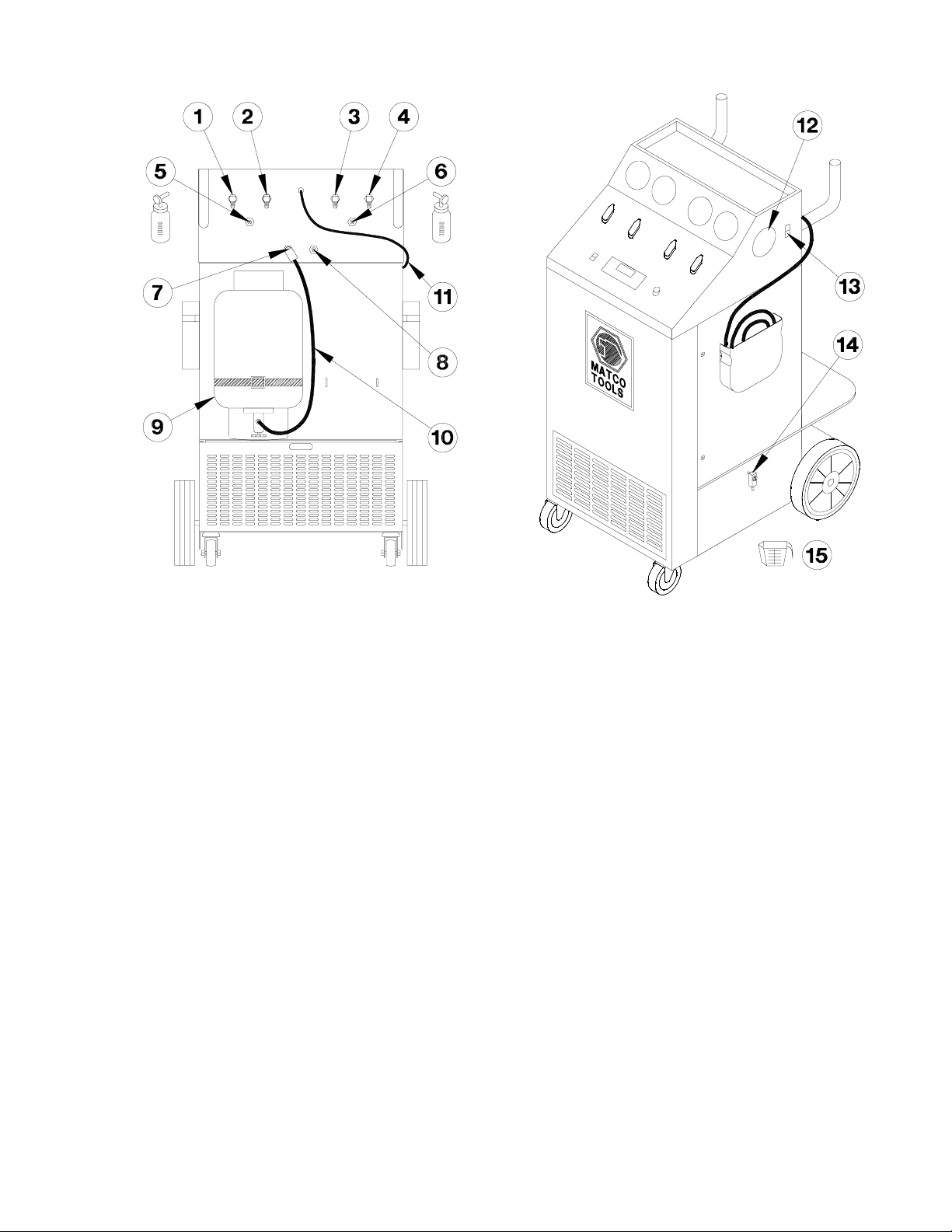
CONFIGURATION
1 Port for R134a High Side Red Hose 10 Yellow Hose
2 Port for R134a Low Side Blue Hose 11 Power Cord
3 Port for R12 High Side Red Hose 12 Purge Gauge R134a
4 Port for R12 Low Side Blue Hose 13 Purge Switch
5 Port for Oil Charge - R134a High Side 14 Oil Drain Valve
6 Port for Oil Charge - R12 High Side 15 Oil Measuring Cup
7 Fill Port for R134a (Attach Anti-Blowback Valve end of Yellow Hose to port)
8 Fill Port for R12 (Attach Ball Valve end of Yellow Hose to port)
9 Cylinder of New Refrigerant
Notes: Item 9 - Cylinder of new or recycled refrigerant must be connected to put LIQUID
refrigerant into the Fill Port.
Item 7 & 8 - End of Yellow Hose with anti-blowback valve (R134a) or ball valve (R12)
must be connected to the respective Fill Port to prevent release of refrigerant when the
hose is disconnected.
Page 3
Page 6
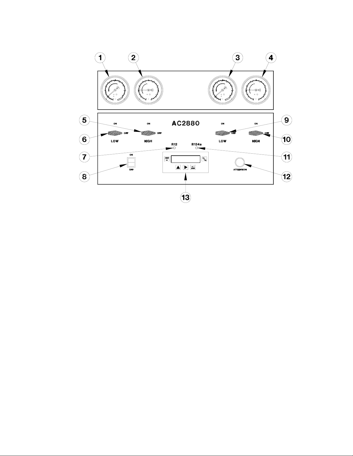
CONTROL PANEL
1 Low Pressure Gauge - R12
2 High Pressure Gauge - R12
3 Low Pressure Gauge - R134a
4 High Pressure Gauge - R134a
5 High Side In/Out Valve - R12
6 Low Side In/Out Valve - R12
7 Function Indicator Light - R12 selected with Cursor Key
8 Power Switch - Illuminated
9 Low Side In/Out Valve - R134a
10 High Side In/Out Valve - R134a
11 Function Indicator Light - R134a selected with Cursor Key
12 Attention Indicator Light
13 Keypad
Page 4
Page 7

KEYPAD FUNCTIONS
Scroll Key Press to scroll through function options
or to increase numeric values shown on
the display.
Cursor Key Press to scroll flashing cursor on the
display prior to numeric or Yes/No
entries. Also used to select R12 or
R134a refrigerant.
Enter Key Press to confirm data entry.
Reset Key Press to halt program sequence and
return to Main Menu.
Units Key Press to change unit of measure for
weight displays.
- CAUTION -
Always use fingers to operate keypad.
Use of sharp objects will cause damage.
Page 5
Page 8

FILL CHARGE CYLINDER
NNNN NNNN NNNN EXTREMELY IMPORTANT NNNN NNNN NNNN
Always connect Yellow Hose (10) to Cylinder (9) first and
then connect other end of hose with anti-blowback valve
to Fill Port (7 or 8) on AC2880.
This procedure is used to quickly transfer refrigerant from a
cylinder of recycled or new refrigerant into the AC2880 charge
cylinder. The fill process will continue until the charge cylinder
fills to 13 lbs. Press the [RESET] key during the fill process if a
smaller total amount of refrigerant is desired.
1. Connect a cylinder of recycled or new refrigerant to the
appropriate fill port on the rear of AC2880 using the yellow
hose. An adapter is provided to permit connection to a
cylinder of R134a having a 1/4 flare fitting.
Liquid refrigerant must be transferred into the charge
cylinder. Therefore, connect to the liquid port of a DOT
cylinder of recycled refrigerant and leave cylinder upright or
connect to the port of new refrigerant and invert cylinder.
PROBLEMS ?
Refer to Page 19 should
problems be encountered using
the Fill Cylinder procedure.
Pressure differential between
the cylinder of new refrigerant
and the internal AC2880 charge
cylinder greatly affect the
efficiency and speed of the Fill
Charge Cylinder procedure.
2. Open valve on cylinder connected to the fill port.
3. Turn on power.
4. Press [>] key four times.
5. Observe displays as shown to the left and enter data when
prompted.
6. Press [#] key to move from one display to the next.
Data Entry & Error Messages
The fill process will stop if the cylinder of recycled or new
refrigerant is emptied. Press the [RESET] key to return to the
main menu.
HIGH PRESSURE - SEE MANUAL (Note A)
This message will be displayed periodically during the fill
process. Do not be concerned as this is normal.
CYLINDER FULL - GO TO CHARGE (Note B)
If the charge cylinder fills to the maximum capacity of 17.5 lbs.
during the fill process this message will be displayed. Press the
[#] key to return to the main menu and go to the charge
procedure to transfer refrigerant to an A/C or an external
cylinder.
Page 6
Page 9

RECYCLE
1. Connect red and blue hoses to A/C and open valves.
2. Turn on power.
3. Press [>] key one time.
4. Observe displays as shown to the left and enter data when
prompted.
5. Press [#] key to move from one display to the next.
Data Entry & Error Messages
RECYCLE HOLD TIME
The AC2880 will recover refrigerant from the A/C until a stable
vacuum is sensed for at least two minutes. Times greater than
two minutes can be entered for the recycle hold time. The time
entered will be saved as the default.
HIGH PRESSURE - SEE MANUAL (Note A)
A condition of high pressure during the recycle process will
cause this message to be displayed. Turn the power off and
contact RTI Technical Service for assistance.
CYLINDER FULL - GO TO CHARGE (Note B)
If the charge cylinder fills to a maximum capacity of 17.5 lbs.
during the recycle process this message will be displayed. Press
the [#] key to return to the main menu and go to the charge
procedure to transfer refrigerant to an external cylinder.
Page 7
Page 10

DEEP VACUUM
1. Connect red and blue hoses to A/C and open valves.
2. Turn on power.
3. Press [>] key two times.
4. Observe displays as shown to the left and enter data when
prompted.
5. Press [#] key to move from one display to the next.
Data Entry & Error Messages
A/C HAS PRESSURE - GO TO RECYCLE (Note A)
This message will be displayed if there is still refrigerant in the
A/C. This refrigerant must be recycled before a deep vacuum
can be performed.
ENTER VACUUM TIME
Sets total time a vacuum will be drawn on the A/C.
PERFORM VACUUM LEAK TEST (Note B)
Yes - process will stop to allow checking for leaks. The display
will show total time since the vacuum pump shut off. A leak is
indicated if by an increasing pressure on the gauges.
CLOSE VALVES AND ADD OIL NOW (Note C)
Yes - process will stop so that oil can be added. Attach a filled
oil charge bottle to the oil charge port. When prompted, close
In/Out valves and open the valve on the bottle until the desired
amount of oil is drawn into the A/C. Go immediately to the
charge process.
Page 8
Page 11

0F R12 R134a
PURGE AIR - DRAIN OIL
30 42 40
32 44 42
34 46 44
36 48 46
38 50 49
40 52 51
42 54 54
44 57 56
46 59 59
48 61 61
50 64 64
52 66 67
54 69 70
56 72 72
58 74 76
60 77 78
62 80 82
64 83 85
66 85 88
68 88 92
70 92 95
72 95 97
74 98 104
76 102 107
78 105 110
80 108 114
82 112 118
84 115 123
86 118 127
88 123 130
90 127 135
92 130 140
94 135 145
96 138 148
98 143 153
100 147 157
102 150 163
104 155 167
106 160 173
108 165 180
110 168 185
112 173 190
114 178 195
116 183 200
118 188 207
120 193 213
IMPORTANT: Air must be purged and oil drained after each
recycle procedure. Failure to do so will cause excess air to
be introduced into the A/C during charge and the AC2880
will fill with excess oil causing serious operational
problems.
During automatic operation only, the AC2880 will stop after
the deep vacuum procedure and display PURGE AIR AND
DRAIN OIL as a reminder.
1. Turn on power.
2. Press the purge switch for five seconds.
3. Slowly open oil drain valve and drain oil into measuring cup.
Leave valve open and go to next step.
4. Measure the room temperature.
5. Find the corresponding pressure for this temperature on the
appropriate R12 or R134a purge chart.
6. Compare this pressure from the chart with that indicated on
the purge gauge on the side of the AC2880. If the gauge
shows a higher pressure, press the purge switch until the
pressure drops to the pressure shown in the chart.
7. Close oil drain valve.
8. Press the purge switch for five seconds to complete the
purge procedure.
Purge Chart
Page 9
Page 12

CHARGE
1. Connect red and blue hoses to A/C and open both hose
valves.
2. Open either the low or high side In/Out valve on the AC2880
according to the A/C manufacturer’s recommendation for
charging the system.
3. Do not run the A/C during the charge procedure.
4. Turn on power.
5. Press [>] key three times.
6. Observe displays as shown to the left and enter data when
prompted.
7. Press [#] key to move from one display to the next.
Data Entry & Error Messages
ENTER CHARGE AMOUNT
Enter the charge amount according to the manufacturer’s
specification.
LOW LEVEL, GO TO FILL CYLINDER (Note A)
This message will be displayed if the amount of refrigerant in the
AC2880 charge cylinder is less than the charge amount entered.
Press [#] key to return to the main menu. Go to the Fill Cylinder
procedure to add refrigerant to the charge cylinder.
CHARGE COMPLETE - EVACUATE HOSES
This screen is displayed at the completion of the charge
procedure. Press [#] key to return to the main menu.
Both high and low In/Out valves on the AC2880 can now be
closed. Start the A/C and monitor the performance.
Close both hose valves when A/C performance monitoring is
complete. Disconnect hoses from A/C. A recycle procedure
should be performed to evacuate refrigerant from the hoses.
Page 10
Page 13

AUTOMATIC
1. Connect red and blue hoses to A/C and open valves.
2. Turn on power.
3. Press [#] key to select automatic mode.
4. Observe displays as shown to the left and enter data when
prompted.
5. Press [#] key to move from one display to the next.
Data Entry & Error Messages
RECYCLE HOLD TIME
The AC2880 will recover refrigerant from the A/C until a stable
vacuum is sensed for at least two minutes. Times greater than
two minutes can be entered for the recycle hold time. The time
entered will be saved as the default.
ENTER VACUUM TIME
Sets total time a vacuum will be drawn on the A/C.
PERFORM VACUUM LEAK TEST
Yes - process will stop to allow checking for leaks.
ADD OIL
Yes - process will stop so that oil can be added.
ENTER CHARGE AMOUNT
Enter the charge amount according to the manufacturer’s
specification.
LOW LEVEL, GO TO FILL CYLINDER (Note A)
This message will be displayed if the amount of refrigerant in the
AC2880 charge cylinder is less than the charge amount entered.
Press [#] key to return to the main menu. Go to the Fill Cylinder
procedure to add refrigerant to the charge cylinder.
Page 11
Page 14

AUTOMATIC (Continued)
HIGH PRESSURE - SEE MANUAL (Note B)
A condition of high pressure during the recycle process will
cause this message to be displayed. Turn the power off and
contact RTI Technical Service for assistance.
CYLINDER FULL - GO TO CHARGE (Note C)
If the charge cylinder fills to a maximum capacity of 17.5 lbs.
during the recycle process this message will be displayed. Press
the [#] key to return to the main menu and go to the charge
procedure to transfer refrigerant to an external cylinder.
PUMP OFF ''
Process will stop to allow checking for leaks if Y was entered at
PERFORM VACUUM LEAK TEST on previous page. The
display will show total time since the vacuum pump shut off. A
leak is indicated if by an increasing pressure on the gauges.
PURGE AIR AND DRAIN OIL
Process will stop so that air can be purged and oil drained. Refer
to previous section on purging air and draining oil for
instructions.
IMPORTANT: Air must be purged and oil drained. Failure to
do so will cause excess air to be introduced into the A/C
during charge and the AC2880 will fill with excess oil
causing serious operational problems.
CLOSE VALVES AND ADD OIL NOW (Note E)
'' MIN - CONTINUE (Note D)
''''
Process will stop so that oil can be added if Y was entered at
ADD OIL? on previous page. Attach a filled oil charge bottle to
the appropriate oil charge port. When prompted, close In/Out
valves and open the valve on the bottle until the desired amount
of oil is drawn into the A/C.
Page 12
Page 15

STORED DATA
1. Turn on power.
2. Press [>] key five times.
3. Observe displays as shown to the left.
4. Press [#] key to move from one display to the next.
Information Displayed
FILTER HOURS
This display shows total hours that refrigerant has been recycled
through the filtering system of the AC2880.
After every 25 hours, the display (shown to the left) will remind
the technician that one or both filters should be changed as soon
as possible. This will be displayed continually, prior to the main
menu until reset.
Refer to the section on maintenance for instructions on changing
filters.
The CHANGE FILTER message should then be reset as follows:
While the FILTER HOURS message is displayed, press and
hold the [<] key and then press the [RESET] key.
TOTAL RECYCLED
The total refrigerant recycled by the AC2880 is displayed. This
total can not be reset to zero.
This total does not include refrigerant added directly to the
charge cylinder through the rear fill port using the fill cylinder
procedure.
TOTAL CHARGED
The total refrigerant charged by the AC2880 is displayed. This
total can not be reset to zero.
Page 13
Page 16

SET OVER CHARGE AMOUNT
A one ounce over charge is added during each charge
procedure to compensate for refrigerant loss in the service
hoses. This can be programmed to accommodate different
operating conditions as follows:
1. Remove rear panel by releasing the two black latches on
each side of the AC2880.
2. Close all valves and turn on power.
3. Press [>] key five times.
4. Observe displays as shown to the left and refer to the
illustration below for the following steps.
5. Look into the AC2880 from the R12 side and locate metal
covered circuit board mounted on the underside of the top
panel.
6. Remove calibration tool.
7. Insert un-threaded end of calibration tool into access hole
and GENTLY PRESS the calibration switch.
8. Press [>] key one time.
9. Enter amount desired for over charge - note the unit of
measure is kg. (1 ounce = 0.02835 kg)
10. Press [#] key to accept the new value for over charge.
11. Replace calibration tool and rear panel.
Calibration Tool Part Number 360-81214-00
Page 14
Page 17

MAINTENANCE
The AC2880 will provide many years of faithful service if properly maintained. Following is a checklist
of items which will ensure the AC2880 performs at peak efficiency and presents an image to your
customers that your shop performs high tech A/C service.
^ Use tool tray for storage of tools and accessory adapters. Do not place tools on the front surface
of the unit.
^ Coil and store hoses in the storage pockets on the side of the AC2880 when not in use. Avoid
hanging hoses over the top of the unit.
^ Keep the exterior surfaces clean. Use a mild all purpose cleaner to wipe oil and dirt off the
cabinet.
^ Do not allow the unit to sit outside in direct sunlight or inclement weather. Excessive moisture
may cause damage and will void the warranty.
^ The AC2880 is not intended to be used for mobile A/C service where the unit is transported to
customer sites. Excessive vibration will shorten component life.
^ Be gentle when moving the AC2880 around the shop. Tip the unit and ease the front casters over
any obstacles such as door jams and potholes.
^ Periodically remove the rear cover and check for refrigerant leaks inside the AC2880 using a leak
detector. A small leak found early will prevent future undetected loss of refrigerant.
^ Use regulated, clean shop air to remove debris from the fins of the condenser coils. Be careful
and do not disturb any internal components.
^ Periodically remove front louvered panel and check oil levels in both compressors. Oil should be
visible in the oil sight tube when the compressor is not operating. If oil is not visible, call RTI
Technical Support 800-468-2321.
^ Change filters when the display indicates a filter change is due.
FILTER CHANGE
After every 25 hours, the display will remind the technician that filters should be changed as soon as
possible. This will be displayed continually, prior to the main menu until reset. There are two filters on
each side of the AC2880. The large inlet filters must be changed after every 25 hours while the smaller
outlet filters must be changed after every 50 hours.
Turn power off and remove rear cover to change filters. The foam insulation on the smaller outlet filter
must be removed from the old filter and installed on the new one.
Check for leaks after replacing filters.
Reset the change filter message as described in the stored data section.
Inlet Filter P/N 026-80077-00 Outlet Filter P/N 026-80069-00
Page 15
Page 18

P/N DESCRIPTION
PARTS LIST - R12 SIDE
AC2880
1 024-80035-00 Rocker Switch SPST
(Mom-On)
2 026-80071-02 Purge Gauge
0-500 psig
3 360-81309-00 Low Pressure Switch
3psig - 8InHg
4 360-81436-00 Solenoid 1S22 Assy
5 360-81428-00 Internal Cylinder Assy
(DOT)
6 360-81426-01 Assy Heater Belt 120V
7 360-81385-00 Solenoid 1S25 Assy
8 031-80000-00 Load Cell 35Kg
9 360-81307-00 High Pressure Switch
261 psig
10 360-80280-00 Condenser Assy
11 360-81434-00 Manifold Assy R12
12 026-80077-00 Combo Filter 3/8 Flare
(Long)
13 026-80069-00 Combo Filter 3/8 Flare
(Short)
14 024-80037-00 Contactor ½ HP 120V 3
NO & 1 NC
15 360-81381-00 Solenoid 1S12 Assy
16 360-81389-00 Tube Assy Compressor
Inlet R12
17 360-81379-00 Solenoid 1S9 Assy
18 360-81356-01 Compressor Assy 120V
Page 16
Page 19

PARTS LIST - R134a SIDE
P/N DESCRIPTION
AC2880
1 360-81435-00 Manifold Assy R134a
2 026-80077-00 Combo Filter 3/8 Flare
(Long)
3 026-80069-00 Combo Filter 3/8 Flare
(Short)
4 360-81391-00 Tube Assy Compressor
Inlet R134a
5 024-80037-00 Contactor ½ HP 120V
3 NO & 1 NC
6 360-81386-00 Solenoid 2S25 Assy
7 360-81382-00 Solenoid 2S12 Assy
8 360-81356-01 Compressor Assy 120V
9 024-80035-00 Rocker Switch SPST
(Mom - On)
10 026-80071-02 Purge Gauge
0-500 psig
11 360-81309-00 Low Pressure Switch
3psig - 8InHg
12 360-81437-00 Solenoid 2S22 Assy
13 360-81428-00 Internal Cylinder Assy
(DOT)
14 360-81426-01 Assy Heater Belt 120V
15 360-81380-00 Solenoid 2S9 Assy
16 031-80000-00 Load Cell 35Kg
17 360-81307-00 High Pressure Switch
261 psig
18 360-80280-00 Condenser Assy
Page 17
Page 20

PARTS LIST - CONTROL PANEL - AC2880
P/N DESCRIPTION
1 026-80065-03 Low Gauge 30 InHg - 120 psig
2 022-80027-00 In/Out Valve 2-Way Open CCW
3 024-80040-00 Rocker Switch SPDT - Amber 125V
4 024-80059-00 Keypad Membrane
5 026-80071-03 High Gauge 0"-500 psig
6 025-80128-00 Lamp Holder w/Clear Bulb 120V
7 025-80131-00 Lens Assy Amber
8 025-80127-00 Clear Bulb Bayonet Base 120V
9 024-80067-01 Circuit Board (2780E/2880) 120V
Page 18
Page 21

TROUBLESHOOTING FILL CYLINDER PROCEDURE
1. The cylinder of new refrigerant should be at ambient temperature or greater for best
performance of the Fill Cylinder procedure. Make sure the cylinder was not recently moved
from an air-conditioned storage room to a warm work area. Place the cylinder on a block
of wood if necessary to elevate it from a cool concrete floor. Application of a heat belt to
the cylinder will greatly enhance the speed.
2. Verify that the cylinder of new refrigerant is up-side-down as shown in the figure on page
4 and that the cylinder valve is open.
3. If filling the Charge Cylinder from a DOT Cylinder, make sure the hose is connected to the
liquid port and the DOT Cylinder is right-side-up.
4. If the yellow hose was connected to the Fill Port the first time the AC2880 was used,
there may be excessive air in the AC2880 Charge Cylinder. At least 4 lbs. of refrigerant
must be recovered/recycled into the AC2880 Charge Cylinder following the
Recover/Recycle procedure on Page 6. During this process, the air in the AC2880 Charge
Cylinder will be automatically purged.
5. Verify that the cylinder of new refrigerant has liquid refrigerant in it by shaking the cylinder
or weighing the contents. A minimum of 4 lbs. of liquid is required.
6. Verify that the Yellow Hose is connected correctly from the
Cylinder to the Fill Port.
R12 Side (Port 8) ...
The Fill Port is equipped with a valve core. A Depressor
must be present in the end of the hose (see figure) closest
to the shutoff valve. This end of the hose with the shutoff
valve must be connected to fill port 8 on the AC2880.
The depressor in the hose may be adjustable, so extend the
depth of the depressor by using needle-nose pliers.
R134a (Port 7)
Make sure the end of the hose with the anti-blowback valve
is connected to fill port 7.
There may be a machine fault if the above steps do not result in a successful
increase of weight shown on the display after running the Fill Cylinder
procedure for a minimum of 15 minutes.
Contact RTI Technical Support at 800-468-2321 (Ext.259) for help.
Page 19
 Loading...