

MAHLE CWL-20E Operation Manual
Operation Manual
Wireless w
heel lift system
MAHLE CWL-20E
EN
Patents pending

en | 2 |
CWL
-
20E
EVERY PERSON WHO OPERATES THIS
READ THIS MANUAL
EQUIPMENT NEEDS TO KNOW AND
UNDERSTAND ALL OF THE INFORMATION IN
THIS MANUAL – FAILURE TO DO SO COULD
RESULT IN SERIOUS INJURY OR DEATH.
CAREFULLY AND
RETAIN FOR YOUR
RECORDS

CWL-
20E
| 3 |
en
Contents
Contents
1. Safety Regulations ................................................ 4
1.1 Warnings ....................................................... 4
2. Foreword ................................................................ 6
2.1 From the manufacturer ................................. 6
3. Symbols Use .......................................................... 6
3.1 Signal words ................................................. 6
4. FCC Part 15 Statement for User’s Manual ........... 6
4.1 Operation of equipment ................................ 6
5. Responsibilities ..................................................... 7
5.1 Receiving inspection ..................................... 7
5.2 Owner and/or operator responsibilities ......... 7
6. Specifications ........................................................ 7
6.1 CWL-20E ...................................................... 7
7. Product Description .............................................. 8
7.1 Component identification .............................. 8
9. Battery information ............................................. 17
9.1 Battery type (lift unit) ................................... 17
9.2 Battery type (touch screen controller) ......... 17
9.3 Charging the batteries ................................. 17
9.4 Battery life ................................................... 18
10. Emergency procedures ....................................... 19
10.1 Emergency stop .......................................... 19
10.2 Manual lowering .......................................... 19
11. Using Multiple Lifts in the Same Work Area ...... 20
11.1 Adjusting lift communication frequency ...... 20
12. Maintenance and Inspection .............................. 21
12.1 Structural inspection ................................... 21
12.2 Maintenance instructions ............................ 22
12.3 Periodic lubrication ..................................... 22
12.4 Valve cleaning and inspection ..................... 22
8. Operation ............................................................... 9
8.1 Preparing the work area ................................ 9
8.2 Prepare the vehicle ....................................... 9
8.3 Prepare the lift units .................................... 10
8.4 Lift system initialization ............................... 11
8.5 Touch screen controller to lift
communication ........................................... 12
8.6 Main operation screen ................................ 13
8.7 Raising/lowering the vehicle ........................ 14
8.8 Lowering a vehicle to the ground ................ 14
8.9 Single/paired operation ............................... 15
8.10 Park mode .................................................. 16
8.11 Options ....................................................... 16
8.12 Status indicators ......................................... 16
8.13 Changing the touch screen frequency
on the lift units ............................................ 16
12.5 Lift table adjustment ................................... 23
12.6 Sensor adjustment ...................................... 23
12.7 Electronic components ............................... 23
12.8 Control box removal .................................... 24
13. Optional Adapters ............................................... 25
Installing the adapters ........................................... 25
14. Troubleshooting .................................................. 26
15. Maintenance Chart .............................................. 28
16. Notes .................................................................... 30
en | 4 |
CWL
-
20E
Safety Regulations
1. Safety Regulations
1.1 Warnings
Failure to follow all of these safety instructions can
lead to severe injury or death from a sudden loss of
the load. Contact the manufacturer at the numbers or
address printed on the back cover of this manual if
you have any questions.
Anyone who operates this jack must read and
understand all the instructions and warnings
provided with this jack before being allowed to use
it. All operators must be careful, competent, trained,
and qualified in the safe operation of the jack. The
owner (or other responsible individual) must ensure
that any operator observes the proper safety
procedures for using this jack at all times. If the
operator does not read well or is not fluent in English,
the owner / manager must read and review the
instructions and warnings in the manual with the
operator in the operator's native language to be sure
that the operator will use the jack properly.
The owner / manager must keep this manual for
future reference, and make sure the warning labels
on the jack are legible and intact at all times.
Replacement labels and manuals are available from
the manufacturer. Call the manufacturer using the
contact information on the back cover of this manual
if you have any questions.
Make sure the load does not exceed the maximum
capacity of the lift. Maximum capacity is 10,000 lbs.
/ 4,540 kg. per lift. Never use the lift system to raise or
support more than maximum capacity per lift. Never
use a lift as a stand to support more than maximum
capacity per lift.
NEVER modify the product in any way.
Modifications (other than those explicitly discussed in
this manual – e.g., use of optional small wheel
adapters) may cause the lift to perform improperly,
resulting in injury or death.
Always use lift on a hard level surface, capable of
sustaining the load. Be sure surface is clean and free
of debris, cracks, and chips.
The lift system is designed to lift over-the-road
vehicles with rims of at least 21 inches in diameter
(14 inches in diameter if the manufacturer supplied
optional adapters are used). NEVER use the lift
system on vehicles with rims
diameter (14 inches if adapters are used).
less
than 21 inches in
Use the lifts only in pairs of 2 or 4 lift units, on the
opposite ends of the same axle. Never lift using a
single unit.
NEVER use the lift system to raise a vehicle by the
frame or structural member. The lift is designed to
be used only beneath the vehicle tires.
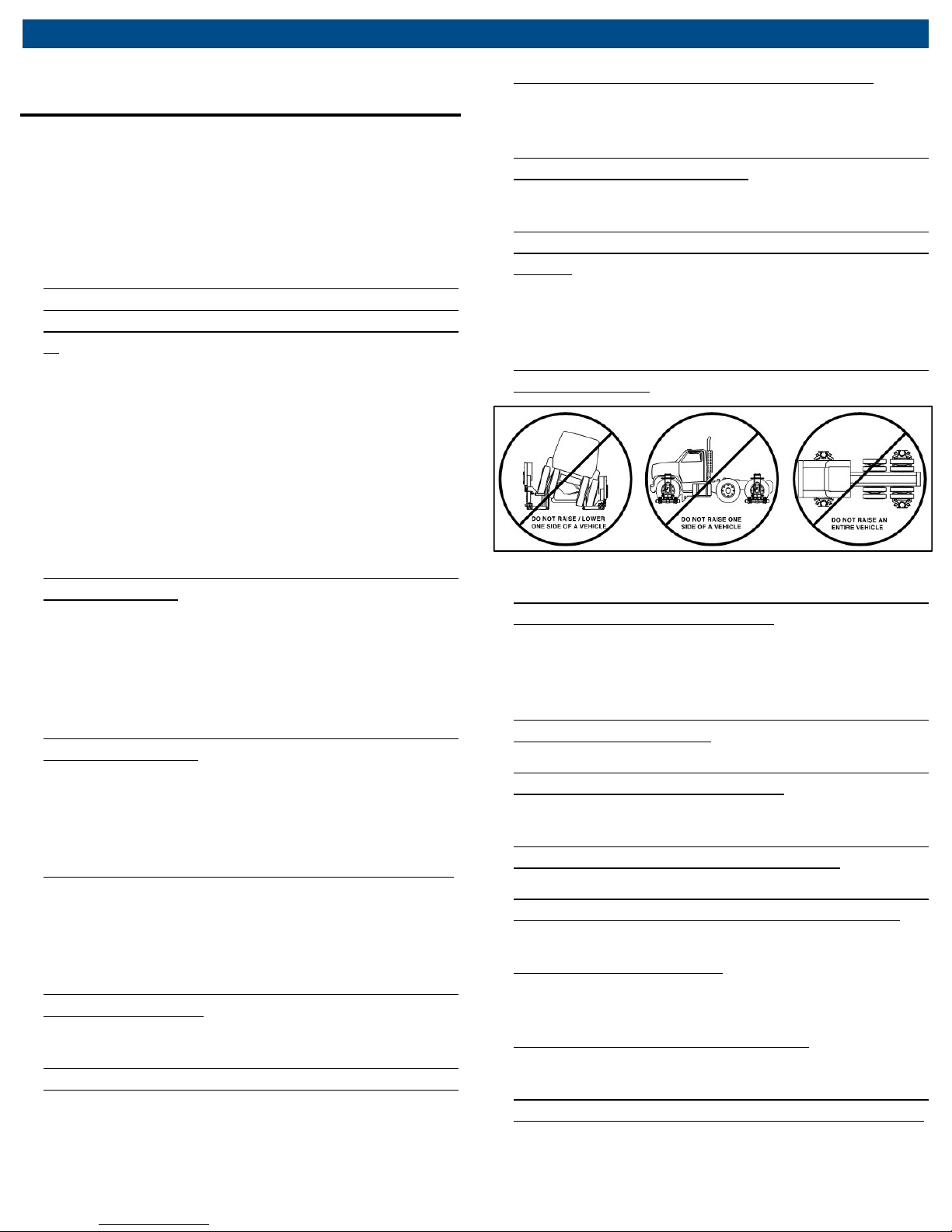
DO NOT raise one end of a vehicle if the opposite
end is supported by stands or another lifting
device. When using two lift units to raise one end of a
vehicle, the opposite end of the vehicle must be in
contact with the ground, transmission in neutral and
parking brake released.
To prevent tipping, never raise or lower just one
side of a vehicle.
Fig. 1: Warnings
DO NOT place hands, feet, other body parts, or
clothing on or near the lift table. There are potential
pinch points that can injure hands and fingers or
possibly grab clothing and pull body parts into pinch
points.
NEVER stand under the lift or vehicle when it is
being raised or lowered.
NEVER operate lift system from a distance that the
work area is not plainly visible, another room, or
from under the vehicle.
NEVER use the lift system in conjunction with any
other equipment used to raise a vehicle.
Never use blocks, adapters, or accessories that
have not been provided by the manufacturer, or
cribbing devices of any kind with this lift system.
To reduce the risk of fire, do not operate equipment
in the vicinity of open containers of flammable liquids
(gasoline).
To reduce the risk of electric shock, do not use on
wet surfaces or expose to rain.
NEVER raise the lift system or an individual lift
when an automatic pin is partially or fully inserted.
If a lift raises against an inserted pin, stop raising
immediately.

CWL-
20E
| 5 |
en
Contents
NEVER use the manual operation procedure as a
normal operation to raise or lower a vehicle. The
manual operation procedure is intended for use only
when the normal controls are not functioning.
NEVER use the lift system as a wheel dolly for the
removal of tires.
Always keep the covers closed on the lift units.
Do not operate equipment with a damaged cord or
if the equipment has been dropped or damaged –
until it has been examined by a qualified serviceman.
If an extension cord is necessary, a cord with a
current rating equal to or more than that of the
equipment should be used. Cords rated for less
current than the equipment may overheat. Care
should be taken to arrange the cord so that it will not
be tripped over or pulled.
Do not operate the lift system with air containing
excess moisture or particulate matter.
NEVER allow the lift system to be used unless all
warning labels and instructional decals are in place
and legible.
NEVER use this jack to lower a vehicle if the
vehicle was raised using another lifting device or
devices. The vehicle should be lowered with the
same equipment that was used to properly raise it
(read and follow the warnings and instructions for this
other equipment).
Always use caution while operating this device and
remain mindful of how the device and load will react
during operation of this device.
Do not let cord or hose hang over edge of table,
bench, or counter or come in contact with hot
manifolds or moving fan blades.
Adequate ventilation should be provided in the work
area.
Keep hair, loose clothing, fingers, and all parts of
body away from moving parts.
Use only as described in this manual. Use only
manufacturer’s recommended attachments.
ALWAYS WEAR SAFETY GLASSES. Everyday
eyeglasses only have impact resistant lenses, they are
NOT safety glasses.
Never use the cord to pull the plug from the outlet.
Grasp plug and pull to disconnect.
Failure to understand and obey this warning may
result in personal injury or death.

en | 6 |
CWL
-
20E
Foreword
Immediate
or
injury.
impending
or
injury
Possible
injury
Possible
Possible property
2. Foreword
2.1 From the manufacturer
Thank you for your purchase. To complement the
offering of A/C, fluid and nitrogen service equipment,
MAHLE Service Solutions has partnered with Gray
Manufacturing to provide the highest quality hydraulic
and pneumatic equipment available for the professional
service technician. This equipment adheres to high
standards promised in the MAHLE guarantee including
the assurance of innovation and reliability that comes
with the Gray Manufacturing name. Please contact
MAHLE Service Solutions’ customer service at (800)
468-2321 or tech.mss@us.mahle.com with any
comments or questions.
3. Symbols Use
3.1 Signal words
Signal words call attention to a safety message or
messages, or a property damage message or messages,
and designate a degree or level of hazard seriousness.
Signal words used in this manual include:
Keyword
DANGER
WARNING
CAUTION
NOTICE
Probability of
occurrence
impending danger
Possible
danger
dangerous
situation
damage to
property
instructions not observed
Death
Death
Minor
damage
Severity of danger if
severe
severe
4. FCC Part 15 Statement for
User’s Manual
4.1 Operation of equipment
This device complies with Part 15 of the FCC rules.
Operation is subject to the following two conditions:
(1) This device may not cause harmful interference, and
(2) This device must accept any interference received,
including interference that may cause undesired
operation.
WARNING!
approved by the party responsible for compliance could
void the user’s authority to operate this equipment.
NOTE: This equipment has been tested and found to
comply with the limits for a Class B digital device,
pursuant to Part 15 of the FCC Rules. These limits are
designed to provide reasonable protection against
harmful interference in a residential installation. This
equipment generates, uses, and can radiate radio
frequency energy and, if not installed and used in
accordance with the instructions, may cause harmful
interference to radio communications. However, there is
no guarantee that interference will not occur in a
particular installation. If this equipment does cause
harmful interference to radio or television reception,
which can be determined by turning the equipment off
and on, the user is encouraged to try to correct the
interference by one or more of the following measures:
Reorient or relocate the receiving antenna.
Increase the separation between the equipment
Connect the equipment into an outlet on a
Consult the dealer or an experienced radio/TV
Changes or modifications not expressly
and receiver.
circuit different from that to which the receiver
is connected.
technician for help.

CWL
-
20E
7 |
en
Responsibilities
5. Responsibilities
5.1 Receiving inspection
Before attempting to operate this equipment, thoroughly
read and understand this manual. Completely remove all
tape and packaging. Inspect the equipment immediately
upon delivery. If shipping damage is evident, inform the
delivering carrier immediately and contact the
manufacturer using the contact information on the back
cover of this manual.
5.2 Owner and/or operator responsibilities
All personnel involved in the use and operation of this lift
system must be careful, competent, trained, and qualified
in the safe operation of this equipment and its proper use
when servicing motor vehicles and their components. It is
the responsibility of the employer, owner, and/or manager
to ensure that all personnel working with and around the lift
system know what they are doing, both during normal
operation and in emergency situations. To ensure all
personnel are properly trained and qualified, the following
items must be done prior to using the lift system:
All personnel must know and understand all
instructions and warnings before working with or
around these lifts. “All personnel” includes operators
as well as people working on or in the vicinity of
vehicles raised by the lift system.
All personnel must read and understand the contents
of the owner’s manual. If any personnel are illiterate or
not fluent in English, the employer, owner, and/or
manager must read and discuss the instructions and
warnings with them in a language they understand,
making sure that all personnel know this information
and observe the proper procedures for use of these
lift units.
The employer, owner, and manager are responsible
for maintaining the manual and all on-product
labeling. Labeling should be legible and intact at all
times. The manual must be readily available to all
personnel. Contact the manufacturer to receive
replacement labeling. Replacement (or extra) copies
of the manual are available from the manufacturer.
The employer, owner, and/or manager must enforce
safe work practices with the lift system in order to
ensure that personnel not only know how to use the
lifts safely, but also that they actually do what they
should.
As part of training, the employer, owner, and/or
manager should have all personnel practice normal
and emergency operating procedures without loads
prior to using the lift system to raise loads.
|
This lift system is not a product that personnel can just
“figure out” on their own. This lift system has been
designed to be easy to use, but it requires thoroughly
trained and knowledgeable personnel to use it safely.
Failure to operate this lift system according to the warnings
and instructions can result in severe injury or death.
It is highly recommended that the lift system be operated
using only clean and dry air. Any particulate matter or
moisture in the air can cause poor performance of the
pneumatic valves and/or lead to premature failure of the
valves. If the air system supplying air to the lift system
delivers air with particulate matter or moisture, a
compressed air dryer and filter should be added.
6. Specifications
6.1 CWL-20E
Model CWL-20E US units Metric units
Maximum capacity (each lift) 10,000 lb 4,540 kg
Maximum air pressure 160 psi 11.0 bar
Minimum air pressure for
rated capacity
Minimum air pressure 85 psi 5.9 bar
Minimum wheel diameter
(w/o adapters)
Minimum wheel diameter (w.
adapters)
Maximum tire to fender
clearance
Weight per lift 610 lb 445.4 kg
Adapter weight 22 lb 10 lb
Ground pressure for each lift
(max. load)
Width 41.6 in 105.7 cm
Depth 45.25 in 115.0 cm
Height (lowered) 53.25 in 135.3 cm
Height (raised) 77.25 in 196.2 cm
Charger voltage required 120VAC / 60Hz 120VAC / 60Hz
150 psi 10.3 bar
19 in 48.3 cm
16 in 40.6 cm
8 in 20.3 cm
275 psi 19.3 kg/cm
2
en | 8 |
CWL
-
20E
Product Description
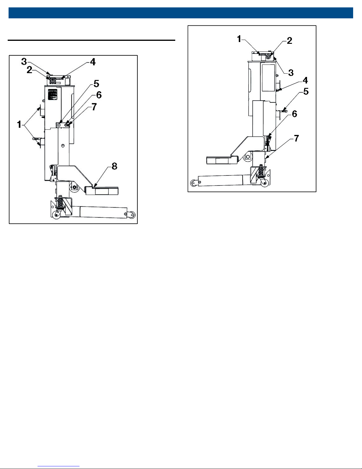
7. Product Description
7.1 Component identification
Fig. 2: CWL-20E side view
1 Hose brackets
2 Master on/off switch
3 Status indicators
4 Screen communication antenna
5 Emergency stop button
6 Communication button
7 Manual raise/lower toggle switch
8 Lift table
Fig. 3: CWL-20E side view 2
1 Lift communication antenna
2 Charger inlet
3 Electronics enclosure
4 Air inlet
5 Air hose
6 Down stop handle
7 Down stop lug
CWL
-
20E
| 9 |
en
Operation
8. Operation
8.1 Preparing the work area
It is important that the surrounding area be properly
chosen and prepared before raising a load.
1. Use the lift system only on hard surfaces capable of
safely supporting the load. The surface must be
strong enough to support the weight of the lift units
and the vehicle being raised. The ground pressure for
each lift unit (at maximum load) is 275 psi (19.3
kg/cm2). The ground pressure listed is an
approximation and may be higher under some
conditions. Hot asphalt can become soft and should
be avoided to prevent property damage or an unsafe
situation.
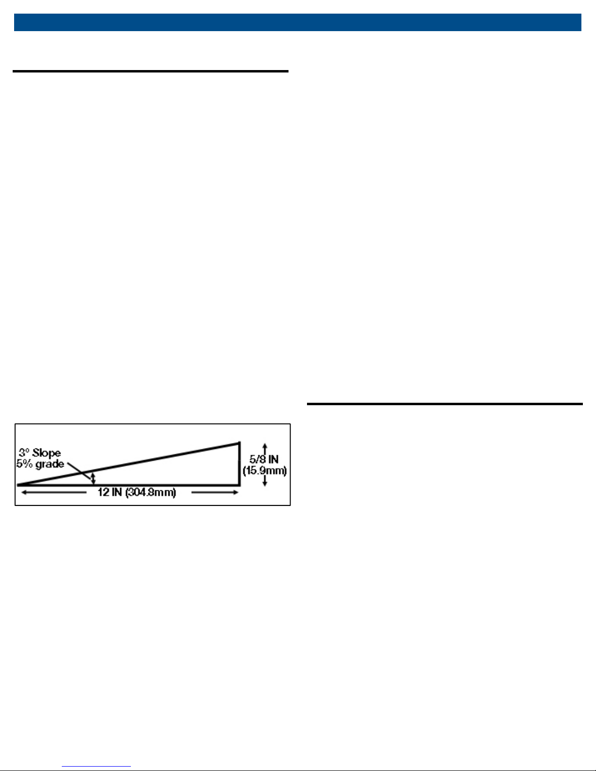
2. Use the lift system only on level, even surfaces. A
level surface is considered to be 3° slope or less. A
surface with 3° slope is equivalent to a 5% grade or
5/8 in. (15.9 mm) rise or drop per horizontal foot
(304.8 mm) (See Fig. 4 below. Note also that for each
degree of slope a surface rises or drops 0.210 in.
(5.33 mm) per horizontal foot (304.8 mm)). The surface
must also be free of ripples, ridges, depressions,
holes, or any undulation (e.g., a seam in a concrete
floor) that would cause only part of the lift unit’s
footprint to be in contact with the floor.
5. If the lift system is used outdoors the operator
assumes all risk. Understanding that these are
portable lifts, it is foreseeable that they can and will be
used outdoors.
WARNING! If lift units are used outdoors the following
conditions must be met:
Do NOT use lift units when wind speeds or gusts
exceed 20 mph to avoid tipping or loss of load.
Do NOT leave lift units unattended when used
outdoors to avoid inadvertent operation by untrained
operators and unforeseen changes in weather
conditions.
Do NOT use lift units outdoors when precipitation of
any type is falling or expected during the time the
units will be used. There is a risk of electric shock if lift
units are used while precipitation is falling.
Do NOT charge lift units while outdoors. Only charge
lift units while indoors to avoid risk of electric shock.
If these conditions cannot be met, move the vehicle
and lift units (separately) to an indoor area where the
lifting operation can be performed safely.
WARNING! NEVER attempt to move or reposition a
lift unit when a vehicle is raised on the lift unit.
8.2 Prepare the vehicle
Fig. 4: Slope of ground under lift
3. Make sure there is adequate clearance above the
highest point of the vehicle (including things like
vehicle exhaust pipes, air dams, etc.) so the vehicle
does not contact any overhead objects when raised
(e.g. ceiling/roof structural components, duct work,
hanging lights, heating/AC units, etc.). The lift system
can raise a vehicle as much as 24” (610 mm, but the
vehicle will extend vertically above this. The height of
the lift unit alone (at maximum lift height) is 77 1/4”
(1,962 mm).
4. Clear the work area (especially the area underneath
the lift unit) of any unnecessary personnel, tools,
equipment and other materials. No unauthorized
personnel should be allowed in the work area where
the lifts are being used.
1. The vehicle’s wheels (or rims; not the tires) should be
at least 19 inches in diameter or else they could fall
through the cradle of the lift table (for example, if the
tires deflate). For wheels 16 to 19 inches in diameter
refer to the “Optional adapters” section on page 25.
2. Check that the tires on the vehicle are properly
inflated and are in road-worthy condition. Make sure
the weight on any single tire does not exceed the
rated capacity of its lift unit, as the total weight of the
vehicle may not be evenly distributed across all lifted
tires. Also, be sure to consider the weight carried by
unsupported axles (i.e. a set of 4 lift units used to
raise a vehicle with three axles).
en | 10 |
CWL
-
20E
Operation
8.3 Prepare the lift units
It is important to prepare the lift units so they can be
used safely together.
1. Make sure the lift system is appropriate for the type
and weight of the vehicle to be lifted. Determine that it
is safe to raise the vehicle by calculating the weight of
the vehicle and the load applied to each lift unit when
the vehicle is raised. NEVER exceed the rated
capacity of an individual lift unit. Also, the lift system
is to be only used in sets where lift units are
positioned on opposite ends of the same axle–
NEVER as a single lift unit or on only one side of a
vehicle.
2. Before each use, you should inspect each lift unit for
any visible signs of wear or damage. See the
“Structural Inspection” section on page 21 for details
about how to inspect the lift unit.
WARNING!
WARNING! If you see any signs of wear or damage,
WARNING!WARNING!
or if there is any indication that the lift unit is not
performing normally, immediately take it out of service
and contact the manufacturer. NEVER use a lift unit
that appears damaged in any way.
3. Before each use, make sure the battery is fully
charged (see the “Charging the batteries” section on
page 17 of this manual). If the battery has not been
given time to fully charge, charge the battery before
use. Failure to fully charge the battery before use can
reduce the life of the battery.
Fig. 5: Position lift table tube against tire
6. Connect an air hose from a compressed air source to
one of the lifts. The air hose from that lift can be
connected to the next lift and so on to daisy chain
them all together. The air hose on the last lift can stay
wrapped on its hose brackets. If desired, separate air
hoses from a compressed air source can be brought
in for multiple lifts. In general, performance will
increase with the number of air hoses brought in.
7. Place the vehicle transmission in neutral and release
the parking brake.
4. Transport the lift units to the work area by wheeling
them manually. A lift unit should be wheeled to the
work area over smooth, level surfaces avoiding any
obstacles or unsafe situations.
WARNING!
WARNING! Jolting caused by the lift unit’s wheels
WARNING!WARNING!
catching on uneven surfaces can cause physical
strain and personal injury.
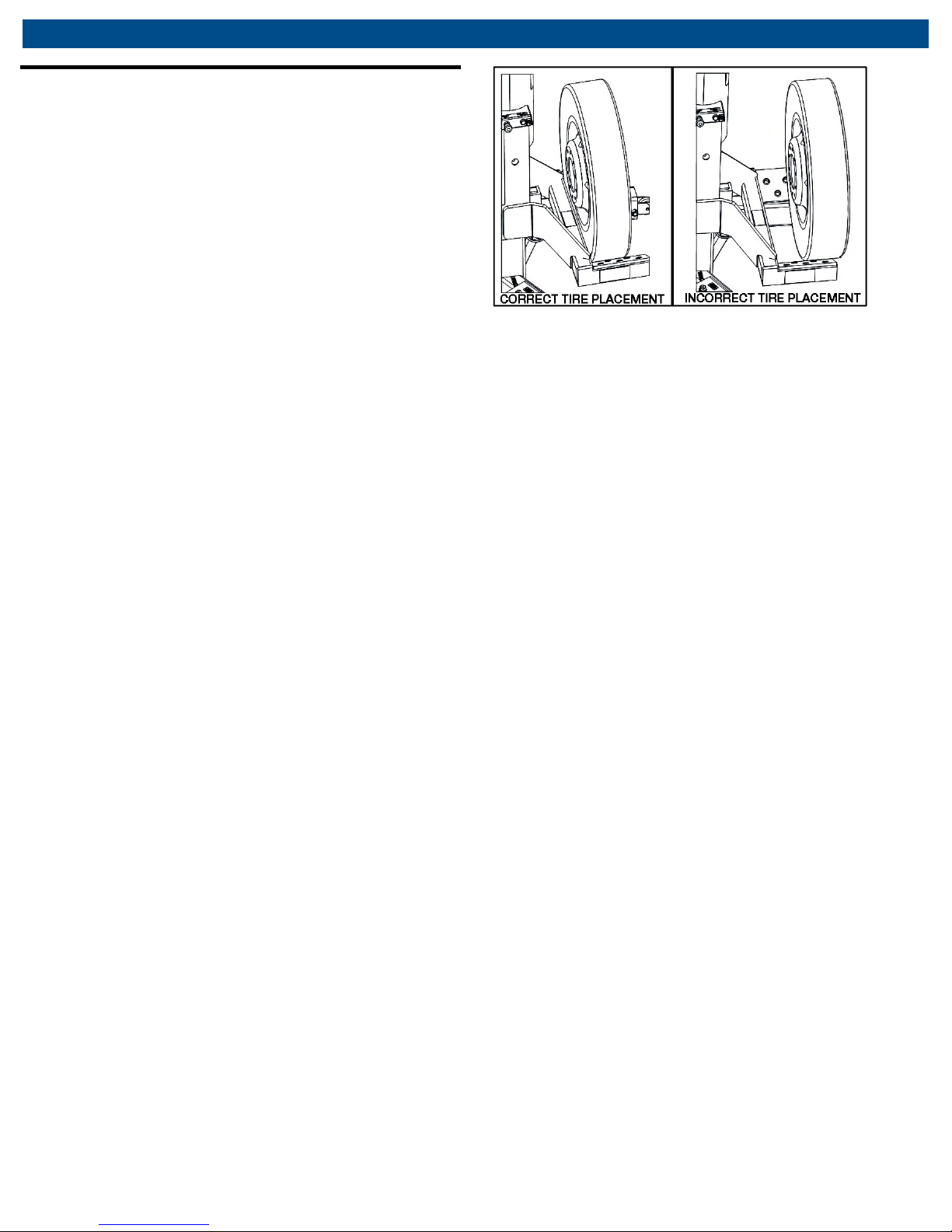
5. Position the lift units so the lift pads cradle the tires at
opposite ends of the same axle. Make sure the lift
pads cradle the tires evenly and are parallel with the
wheel and tire. Position the lift pads under the tire so
the lift table tube contacts the tire (see Fig. 5).
 Loading...