

Operation Manual
Wheel lift system
MAHLE CWL-20
EN
U.S. Patent No. D357,106 & 5,484,134

en | 2 |
CWL
-20
EVERY P
ERSON WHO OPERATES THIS
READ THIS MANUAL
EQUIPMENT NEEDS TO KNOW AND
UNDERSTAND ALL OF THE INFORMATION IN
THIS MANUAL – FAILURE TO DO SO COULD
RESULT IN SERIOUS INJURY OR DEATH.
RETAIN FOR YOUR
CAREFULLY AND
RECORDS

CWL
-20 | 3 |
en
Contents
Contents
1. Safety Regulations ................................................ 4
1.1 Warnings ....................................................... 4
2. Foreword ................................................................ 5
2.1 From the manufacturer ................................. 5
3. Symbols Use .......................................................... 5
3.1 Signal words ................................................. 5
4. Responsibilities ..................................................... 6
4.1 Receiving inspection ..................................... 6
4.2 Owner and/or operator responsibilities ......... 6
5. Specifications ........................................................ 6
5.1 CWL-20......................................................... 6
6. Product Description .............................................. 7
6.1 Component identification .............................. 7
7. Operation ............................................................... 8
7.1 Preparing the lifts and vehicle ....................... 8
7.2 Raising a vehicle ........................................... 8
7.3 Pinning the lifts as stands ............................. 9
7.4 Lowering a vehicle to the ground .................. 9
7.5 Using the lifts with support stands .............. 10
Transferring a load to support stands ................... 10
Removing support stands ..................................... 10
8. Maintenance and Inspection .............................. 11
8.1 Structural inspection ................................... 11
8.2 Air hose inspection ..................................... 11
8.3 Maintenance instructions ............................ 11
8.4 Air control unit cleaning instructions ........... 12
8.5 Lift table adjustment ................................... 12
9. Troubleshooting .................................................. 13
10. Optional adapters ................................................ 13
Installing the adapters ........................................... 13
Using the adapters ................................................ 13
11. Maintenance Chart .............................................. 14
12. Notes .................................................................... 16
en | 4 |
CWL
-20
Safety Regulations
1. Safety Regulations
Use the lifts only in pairs, on the opposite ends of
the same axle.
1.1 Warnings
Failure to follow all of these safety instructions can
lead to severe injury or death from a sudden loss of
the load. Contact the manufacturer at the numbers or
address printed on the back cover of this manual if
you have any questions.
Anyone who operates this jack must read and
understand all the instructions and warnings
provided with this jack before being allowed to use
it. All operators must be careful, competent, trained,
and qualified in the safe operation of the jack. The
owner (or other responsible individual) must ensure
that any operator observes the proper safety
procedures for using this jack at all times. If the
operator does not read well or is not fluent in English,
the owner / manager must read and review the
instructions and warnings in the manual with the
operator in the operator's native language to be sure
that the operator will use the jack properly.
The owner / manager must keep this manual for
future reference, and make sure the warning labels
on the jack are legible and intact at all times.
Replacement labels and manuals are available from
the manufacturer. Call the manufacturer using the
contact information on the back cover of this manual
if you have any questions.
Make sure the load does not exceed the maximum
capacity of the lift. Maximum capacity is 20,000 lbs.
/ 9,070 kg. per lift. Never use the lift system to raise or
support more than maximum capacity per lift. Never
use a lift as a stand to support more than maximum
capacity per lift.
NEVER modify the product in any way.
Modifications may cause the lift to perform
improperly, resulting in injury or death.
Always use lift on a hard level surface, capable of
sustaining the load. Be sure surface is clean and free
of debris, cracks, and chips.
The lift system is designed to lift over-the-road
vehicles with rims of at least 21 inches in diameter
(14 inches in diameter if the manufacturer supplied
optional adapters are used). NEVER use the lift
system on vehicles with rims
diameter (14 inches if adapters are used).
less
than 21 inches in
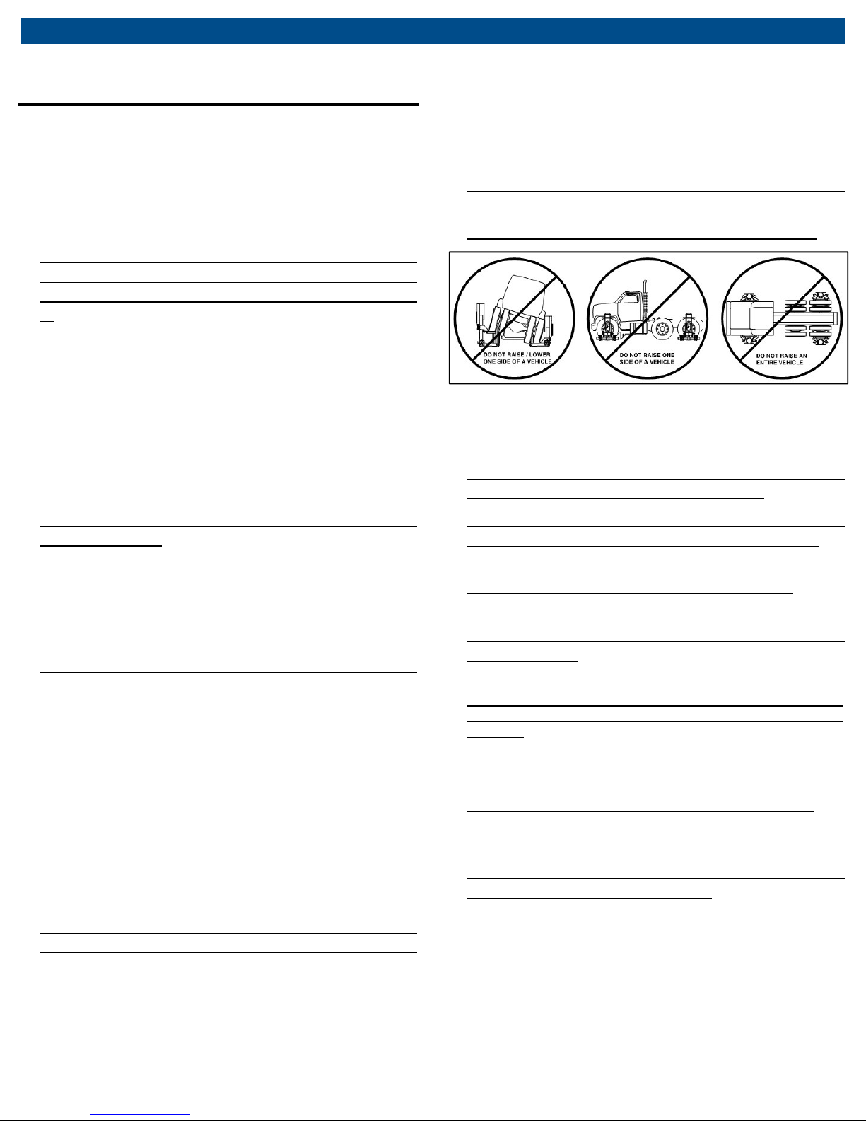
NEVER use the lift system to raise a vehicle by the
frame or structural member. The lift is designed to
be used only beneath the vehicle tires.
To prevent tipping, never raise or lower just one
side of a vehicle.
NEVER lift an entire vehicle with the lift system.
Fig. 1: Warnings
Do not allow any part of your body under the
vehicle until both the lifts are pinned as stands.
NEVER use the lift system in conjunction with any
other equipment used to raise a vehicle.
Never use blocks, adapters, or accessories that
have not been provided by the manufacturer, or
cribbing devices of any kind with this lift system.
NEVER use the lift system as a wheel dolly for the
removal of tires.
NEVER allow the lift system to be used unless all
warning labels and instructional decals are in place
and legible.
NEVER use this jack to lower a vehicle if the
vehicle was raised using another lifting device or
devices. The vehicle should be lowered with the
same equipment that was used to properly raise it
(read and follow the warnings and instructions for this
other equipment).
Always use caution while operating this device and
remain mindful of how the device and load will react
during operation of this device.
Failure to understand and obey this warning may
result in personal injury or death.

CWL
-20 | 5 |
en
Foreword
Immediate
or
injury.
impending
or
injury
Possible
injury
Possible
Possible property
2. Foreword
2.1 From the manufacturer
Thank you for your purchase. To complement the
offering of A/C, fluid and nitrogen service equipment,
MAHLE Service Solutions has partnered with Gray
Manufacturing to provide the highest quality hydraulic
and pneumatic equipment available for the professional
service technician. This equipment adheres to high
standards promised in the MAHLE guarantee including
the assurance of innovation and reliability that comes
with the Gray Manufacturing name. Please contact
MAHLE Service Solutions’ customer service at (800)
468-2321 or tech.mss@us.mahle.com with any
comments or questions.
3. Symbols Use
3.1 Signal words
Signal words call attention to a safety message or
messages, or a property damage message or messages,
and designate a degree or level of hazard seriousness.
Signal words used in this manual include:
Keyword
DANGER
WARNING
CAUTION
NOTICE
Probability of
occurrence
impending danger
Possible
danger
dangerous
situation
damage to
property
instructions not observed
Death
Death
Minor
damage
Severity of danger if
severe
severe

en | 6 |
CWL
-20
Responsibilities
4. Responsibilities
4.1 Receiving inspection
Before attempting to operate this equipment, thoroughly
read and understand this manual. Completely remove all
tape and packaging. Inspect the equipment immediately
upon delivery. If shipping damage is evident, inform the
delivering carrier immediately and contact the
manufacturer using the contact information on the back
cover of this manual.
4.2 Owner and/or operator responsibilities
The owner and / or user must have an understanding of
the manufacturer’s operating instructions and warnings
before using this system. The use of portable lifting
devices is subject to certain hazards that cannot be
avoided by mechanical means, but only by the exercise
of intelligence, care, and common sense. Personnel
involved in the use and operation of equipment shall be
careful, competent, trained, and qualified in the safe
operation of the equipment and its proper use when
servicing motor vehicles and their components.
Examples of hazards are dropping, tipping, or slipping of
vehicles or their components caused primarily by
improperly securing loads, overloading, off-centered
loads, use on other than hard level surfaces, and using
equipment for a purpose for which it was not designed.
Warning information should be emphasized and
understood.
5. Specifications
5.1 CWL-20
Model CWL-20 US units Metric units
Maximum capacity (each lift) 20,000 lb 9,070 kg
Maximum capacity (system) 40,000 lb 18,140 kg
Maximum air pressure 155 psi 10.7 bar
Minimum wheel diameter (w/o
adapters)
Minimum wheel diameter (w.
adapters)
Maximum tire to fender
clearance
System weight 1964 lb 890.9 kg
Weight per lift 982 lb 445.4 kg
Adapter weight 22 lb 10 lb
Width 45 in 114.3 cm
Depth 44 in 111.8 cm
Height (lowered) 63 in 160.0 cm
Height (raised) 93 in 236.2 cm
21 in 53.3 cm
14 in 35.6 cm
8 in 20.3 cm
Air pressure requirements (used in pairs)
The owner / manager must make this manual available to
all personnel using this jack at your direction. They must
read and understand the contents of this manual. If the
operator is not fluent in English, the manufacturer’s
instructions and warnings shall be read to and discussed
with the operator in the operator’s native language by
the purchaser / owner, making sure that the operator
comprehends its contents and observes the proper
procedures for use of this jack.
Owner and / or user must study and maintain for future
reference the manufacturer’s instructions. Owner and /
or user are responsible for keeping all warning labels and
instruction manuals legible and intact. Replacement
labels and literature are available from the manufacturer.
Weight Air pressure
10,000 lbs.
15,000 lbs.
20,000 lbs.
25,000 lbs.
30,000 lbs.
35,000 lbs.
40,000 lbs.
40 psi
59 psi
78 psi
97 psi
116 psi
134 psi
152 psi

CWL
-20 | 7 |
en
Product Description
6. Product Description
6.1 Component identification
Fig. 2: CWL-20 front view
1 Cylinder head plate
2 Handle grips
3 Load retention pin
4 Base post
5 Lift table tube
6 Lift pad
7 Front wheels
Fig. 3: Air control unit components
1 Air control unit
2 Air control levers
Fig. 4: CWL-20 side view
1 Front wheels
2 Roller wheel
3 Downstop lug
4 Downstop pawl
5 Downstop release handle
6 Air hose
7 Air hose holder
8 Swivel caster

en | 8 |
CWL
-20
Operation
7. Operation
WARNING -
To prevent serious injury or death from
a falling vehicle, make sure the vehicle’s rims are at
least 21 inches in diameter (or 14" if adapters are
used). Make sure the tires are properly inflated, to
maintain necessary tire diameter. Make sure weight
on the vehicle axle does not exceed 40,000 lbs.
WARNING -
To prevent serious injury or death from
a falling vehicle, make sure that the hoses avoid all
pinch points and that they do not pass under the
base of a lift. The base lowers slightly as the vehicle
is raised.
7.1 Preparing the lifts and vehicle
1. Before proceeding, review the Safety Instructions
section of this manual.
2. Position the vehicle on a hard, level surface and set
the parking brake.
3. Check that the tires on the vehicle are properly
inflated, to maintain necessary tire diameter.
4. Position the Wheel Lifts so the lift pads are cradling
the tires at opposite ends of the same axle.
Fig. 6: Air control lever
9.
Connect the air hose from the lift on your right to the
right side of the air control unit. Connect the air hose
from the lift on your left to the left side of the air
control unit (see Fig. 6 for connections).
10. Connect the air supply (145 psi max) to the air inlet
port of the air control unit (see Fig. 3 for connection).
7.2 Raising a vehicle
To prevent serious injury or death from a falling vehicle,
operate both air control levers at the same time and
keep the vehicle level as it is raised or lowered.
5. Push the lift pad under the tire until the lift table tube
contacts the tire (see Fig. 5 for identification).
Fig. 5: Lift table tube and pads
6. Release the vehicle’s parking or air brake and place
the transmission in neutral.
7. Uncoil the air hoses from both lifts and route them for
connecting to the air control unit, at either the front or
the rear of the vehicle.
8. Position yourself at the front or rear of the vehicle so
both lifts are visible. Face the vehicle and hold the air
control unit with the air control levers pointing toward
the vehicle and the quick couplers on the underside of
the air control unit. (See Fig. 6 for orientation).
1. Position one unit on each end of the same axle. Make
sure the lift arms fully engage each wheel.
2.
Raise the vehicle by lifting up on both the air control
levers at the same time. Be sure to operate the air
control levers so the vehicle stays level at all times as
it is raised or lowered.
3.
Raise the vehicle until it is 2"- 4" above the desired
working height (the vehicle will lower by that amount
as the downstop lugs engage). Visually confirm that
the downstop pawls will engage downstop lugs at the
same height on each lift. If they will not engage
downstop lugs at the same height, carefully adjust
vehicle level until the lifts are at the same height. See
Fig. 7 and 8 for downstop pawl and lug identification.
Fig. 7: Downstop lug identification

CWL
-20 | 9 |
en
Operation
7.3 Pinning the lifts as stands
1. With the vehicle 2"-4" above the final working height,
carefully lower the lifts by pushing both the air control
levers down at the same time until the downstop
pawls engage the closest downstop lugs.
2. Visually confirm that the downstop pawls are securely
engaged on the downstop lugs of each lift and the
raised axle is level (see Fig. 8).
Downstop
Pawl
Downstop
Lug
Fig. 8: Downstop pawl and lug identification
3. On both lifts, remove the load retention pin from its
holder and insert it through the oblong hole in the lift
stop bar and fully into the corresponding hole in the
downstop lug (see Fig. 9) to pin the lifts as stands.
Load
retention
pin in
holder.
Lift Stop
Bar.
Insert load
retention
pin here to
pin lift as
stand.
Fig. 9: Load retention pin
4. Exhaust all air from both cylinders by pushing both air
control levers down at the same time.
5. Disconnect the air hoses and coil them on the hose
holders on the back of each lift.
7.4 Lowering a vehicle to the ground
To prevent serious injury or death from a falling
vehicle, operate both air control levers at the same
time and keep the vehicle level as it is raised or
lowered.
To prevent serious injury or death, clear the work area
of all tools and equipment. Make sure all personnel
are clear before lowering a vehicle.
1. Use this lift to lower the vehicle only if you used it to lift
the vehicle. Using this lift to lower a vehicle that was
raised with another device (or multiple devices) could
overload the lift to the point of catastrophic failure.
2. Remove the load retention pins and insert them into
their holders.
3. Uncoil the air hoses from both lifts. Be sure the air
hoses are free from all pinch points.
4. Position yourself at the front or rear of the vehicle so
both lifts are visible. Face the vehicle and hold the air
control unit with the air control levers pointing toward
the vehicle and the quick couplers at the bottom of
the air control unit.
5. Connect the air hose from the lift on your right to the
right side of the air control unit and the air hose from
the lift on your left to the left side of the air control unit
(see Fig. 6).
6. Connect the air supply to the air inlet port of the air
control unit (see Fig. 6).
7. Raise both lifts slightly (about 1/2") so the downstop
pawls are raised above the downstop lugs.
8. At each lift, release the downstop pawl by pushing the
downstop release handle toward the lift (see Fig. 10.)
Downstop
Release
Handle
(controls
downstop
pawl).
Push
handle
toward lift
to release
downstop
pawl.
Fig. 10: Push downstop release handle torward lift
9. Lower the lifts by pushing both the air control levers
down at the same time. Be sure to operate the air
control levers so the vehicle stays level. Lower the lifts
to their lowest position do the downstop pawls will
automatically reset.
If you decide to raise the vehicle again before it has
been fully lowered, you must reset the downstop
pawls. To manually reset the downstop pawls, pull
the downstop release handle toward you on each of
the lifts. (See Fig. 7).
10. Place the vehicle transmission in gear (or park) and
engage the brakes.
11. Disconnect the air hoses and coil them on each lift.
12. Move the lifts away from the work area.

en | 10 |
CWL
-20
Operation
7.5 Using the lifts with support stands
To prevent serious injury or death from a falling
vehicle, never put any part of your body under a
vehicle supported by lift system unless the lifts have
the load retention pins properly inserted to pin the lifts
as stands.
Removing support stands
1. Move the lifts into place at opposite ends of the axle
to be lowered and position them so the lift pads will
cradle the tires when contact is made.
2. Carefully follow steps 7-10 under “Preparing the lifts
and vehicle,” section.
To prevent serious injury or death from a falling
vehicle, operate both air control levers at the same
time and keep the vehicle level as it is lowered.
Vehicles that are not supported evenly may shift and
fall. To avoid serious injury or death by crushing,
make sure that the stands used are the same height,
and that they are positioned at the manufacturer’s
recommended locations the same distance from the
lifts on each side of the vehicle.
Transferring a load to support stands
After the vehicle has been raised (following instructions
under the “Raising a vehicle” section) and the wheel lifts
have been pinned as stands (“Pinning the lifts as stands”
section) you can transfer the vehicle to support stands
and remove the wheel lifts, if you choose.
1. Select stands of the same height for each side of the
vehicle. Make sure the stands are capable of
supporting the weight of the vehicle.
2. Identify appropriate manufacturer recommended
locations, suitable for supporting the vehicle on stands,
an equal distance from the lifts on each side of the
vehicle.
3. Clear the work area under the vehicle of all personnel,
then place the stands at the appropriate locations on
each side of the vehicle.
4. Remove the load retention pins and lower the vehicle
down onto the support stands (if the load retention
pins will not pull out easily, raise the vehicle just
enough to free the load retention pins). Make sure the
vehicle comes down evenly on the stands.
5.
When the vehicle is securely supported by the
support stands, lower the lifts to their lowest position
so the downstop pawls are automatically reset.
CAUTION - The downstop pawls will not automatically
reset until lift has been fully lowered. If lift is used
without being lowered completely first, you must
manually reset downstop pawls by pulling the downstop
release handle toward you on each of the lifts.
6.
Disconnect the air hoses and coil them on the air
hose holders on the back of each lift. Pull the lifts
away from the work area
.
3. To raise the lifts, pull up on both air control levers at
the same time. Operate the air control levers so both
of the lift pads contact the tires at the same time.
4. Visually confirm that both lift pads have securely
engaged the tires, and that the lift table tube of each
lift contacts the side of the tire.
5. Raise the vehicle off the support stands by lifting up
on both the air control levers at the same time. Be
sure to operate the air control levers so the vehicle
stays level.
6. Pin the lifts as stands, carefully following the
instructions in “Pinning the lifts as stands,” section.
7. Once the lifts have been pinned as stands, remove
the support stands from under the vehicle; then lower
the vehicle, following the instructions under “Lowering
a vehicle to the ground” section.

CWL
-20 | 11 |
en
Maintenance and Inspection
8. Maintenance and Inspection
WARNING -
knowledgeable person to inspect the jack for signs of
corrosion and / or excessive wear. Visual inspection
should be made before each use of jack, checking for
abnormal conditions. Regular inspections should be
made weekly for daily use and monthly for intermittent
use. Each jack must be inspected immediately if
subjected to an abnormal load or shock. Any jack
which appears to be damaged in any way, is found to
be badly worn, or operates abnormally shall be
removed from service until necessary repairs are
made. Contact the manufacturer using the contact
information printed on the back cover of this manual.
The owner must inspect, or appoint a
If any irregularities or problems are detected during an
inspection, the stand must be removed from service
immediately and repaired. Contact the manufacturer
using the contact information on the back cover of
this manual.
8.2 Air hose inspection
To prevent serious injury or death from a falling vehicle,
or possible serious injury due to bursting air hoses,
replace air hoses only with single-wire reinforced air
hoses from manufacturer, part number 1-271-02002.
The use of any other air hose increases the risk that the
air hose may become pinched or damaged, resulting in
failure of the air hose or of the lift during operation.
Contact the manufacturer.
8.1 Structural inspection
The jack must be removed from service and inspected
for damage immediately if the jack is subjected to an
abnormal shock or load. Never return the Lift system to
service until all damaged components have been
properly repaired or replaced. Always test the lift and
verify proper operation before returning the Lift system
to service. Failure to heed this warning may result in
personal and / or property damage.
To prevent serious injury or death from a falling vehicle,
all inspection and maintenance procedures must be
performed after the jack has been removed from
service. Position the lifts so you have clear access to all
sides of the lift for inspection and service.
Inspect the lifts for any cracks, chips, or signs of
excessive wear. Visually inspect the welds.
Inspect the load retention pins for deformities or
excessive wear — if the deformities or wearing away
of material are easily noticeable without close
inspection, it is excessive. Test the load retention
pins by inserting them through the lift stop bar and
into each downstop lug. If the load retention pin
cannot be inserted fully through the lift stop bar and
into each of the holes in the downstop lugs in all
positions, it is excessively damaged and must be
replaced before the lift can be used again.
Inspect the holes for the load retention pins in the
base post. If these holes show excessive elongation
or wear on the top or bottom surfaces, they must be
repaired before the lift can be placed back into
service. Contact the manufacturer using the contact
information on the back cover of this manual for
repair recommendations.
Inspect the air hoses daily for any signs of cuts,
abrasions, or excessive wear. If any air hose appears
to be damaged, replace it immediately with
manufacturer authorized reinforced steel air hose,
part number 1-271-02002.
Inspect the air fittings daily for cracks and/or
damaged parts. If any show damage, replace them
before putting the Lift system back into service.
8.3 Maintenance instructions
WARNING - All inspection and maintenance procedures
must be performed after the jack has been removed from
service. Failure to do this may result in personal injury
and/or property damage.
All warning and capacity labels should be readable
and complete. Wash external surfaces of jack, labels,
and decals with a mild soap solution.
Lubricate all rotating and sliding portions of the jack
monthly (Fig. 11).
Oil downstop
pivot shaft
and release
springs
monthly
Grease roller wheel monthly.
Grease base post monthly with EP-1 yellow grease.
Grease swivel
casters monthly
Fig. 11: Lubrication points
Oil front wheels
monthly.

en | 12 |
CWL
-20
Maintenance and Inspection
8.4 Air control unit cleaning instructions
Occasionally, pieces of rust, scale or dirt from the airlines
may become lodged under the rubber seals of the air
control unit. This may cause minor air leakage and the lift
system units may slowly raise or lower even though the air
control levers have not been actuated. This minor air
leakage is easily corrected by following the steps below
(refer to Fig. 12 for component identification):
Fig. 12: Air control unit component identification
1. Disconnect the three air hoses attached to the air
control unit.
8.5 Lift table adjustment
The lift system has a 1/2-13 hex head cap screw
mounted inside the top weldment to allow the lift table to
be raised or lowered slightly. The cap screw has been
adjusted at the factory to provide 1/4" to 5/16" of
clearance between the bottom of the lift pads and the
floor.
To raise or lower the lift table, follow the lift table
adjustment steps below:
1. Place the lifts on a level floor in a suitable open area.
2. Raise both lifts onto their lowest downstop.
3. Loosen the jam nut and turn the cap screw a few
turns in the required direction. Clockwise raises the lift
table, counterclockwise lowers it. (See Fig. 13 for
identification.)
Capscrew
Jam Nut
Lift Table
2. Remove the valve bracket.
3. Remove the plug or plugs.
4. Use a stiff wire or pin punch to push the spool out of
the valve body.
5. Carefully examine the rubber seal for any dirt or
foreign material. If foreign material is embedded in the
rubber seal, remove the screw and cup from the end
of the spool, then remove and clean the rubber seal.
Turn the seal over and reassemble it into the cup.
Secure the cup back onto the end of the spool with
the screw.
6. Lubricate the spool with a light chassis grease.
7. Insert the spool with O-ring into the air inlet spool
port.
8. Insert the spool without O-ring into the air exhaust
spool port.
9. Insert the spring(s).
10. Apply thread sealant to the plug(s) and install the
plugs into the valve body. Do not over tighten the
plug(s), as the threads can very easily be damaged.
Fig. 13: Lift table clearance adjustment
4. Tighten the jam nut.
5. Lower the lift to its lowest position and check the lift
table height above the floor.
Repeat the adjustment as needed until each lift has a
minimum of 1/8" clearance between the lift table bottom
and the floor. With the lift table resting on the floor, the
lifts may not easily move around the shop floor.

CWL
-20 | 13 |
en
Tro
ubleshooting
9. Troubleshooting
This section is a list, in which may be encountered and
their solutions. If the solution listed fails to correct the
problem, contact the manufacturer using the contact
information on the back cover of this manual. Please
have the model number, and serial number of your jack
available. The serial number is printed on a tag located
on the right caster brake.
Problem Cause/Solution
•
Fails to lift load
Only one lift raises
Will not cradle tire
Inadequate air pressure; requires 155 psi.
• Lifts are overloaded. Rated capacity is
20,000 lbs. per lift. Use larger-capacity lift.
•
Air hoses are not connected properly,
damaged or pinched.
•
Air control unit is dirty or damaged. See
the “Air control unit cleaning instructions”
section of manual.
•
Air hoses are not connected properly,
damaged or pinched.
• Air control unit is dirty or damaged. See
the “Air control unit cleaning instructions”
section of manual.
• Tire is underinflated or tire diameter is too
large.
• Lift is not fully lowered.
• Vehicle is overloaded. Use other lifting
means.
10. Optional adapters
To prevent serious injury or death from a falling
vehicle, use WL-Adapters only for vehicles with rims
between 14" and 21" in diameter.
Install the WL-Adapters with both hooks in the holes
of the lift pad. Proper installation is shown in Fig. 14.
Installing the adapters
Make sure the wheel rims on the vehicle to be raised are
a minimum of 21" in diameter, unless you are using the
manufacturer supplied adapters with the lift system. With
the adapters, properly positioned on the lift pads,
vehicles with wheel rims of 14" can be safely raised. For
rims of 14-21 inches in diameter, install the adapters as
follows:
Lift will not lower or
lowers erratically
Lift table hits floor
Lift raises slowly
• Vehicle parking brake is set and/or
transmission is in gear.
• Air hoses are not connected properly.
• Air hoses are pinched. Remove load from
lifts using other lifting means; remove air
hoses from pinch point.
• Floor is uneven and/or rough. Raise lift to
lowest downstop.
• Lift table height needs adjustment for
minimum clearance. See the “Lift table
adjustment: section of this manual.
• Low air pressure. Raise air pressure to 145
psi.
• Air control unit is dirty or damaged. See
the “Air control unit cleaning instructions”
section of manual.
• Lifts overloaded. Rated capacity is 20,000
lbs. per lift. Use other lifting means.
Fig. 14: Installing the WL-adapters
Using the adapters
Use the adapters only on vehicles with rims of 14 inches
- 21 inches in diameter. Follow normal operating
instructions to use the lift system with adapters installed.
Fig. 15: Lift table tube identification

en | 14 |
CWL
-20
Maintenance Chart
11. Maintenance Chart
Action Date Details
Receiving inspection
Person
responsible

CWL
-20 | 15 |
en
Maintenance Chart
Action Date Details
Person
responsible

en | 16 |
CWL
-20
Notes
12. Notes

CWL
-20 | 17 | en
Notes

en | 18 |
CWL
-20
Notes

CWL
-20 | 19 | en
Notes

670
-
907
52
MAHLE Aftermarket Inc.
10 Innovation Drive
York, PA 17402 U.S.A.
Phone: (800) 468-2321
Fax: (717) 755-8304
E-mail: tech.mss@us.mahle.com
www.servicesolutions.mahle.com
 Loading...