

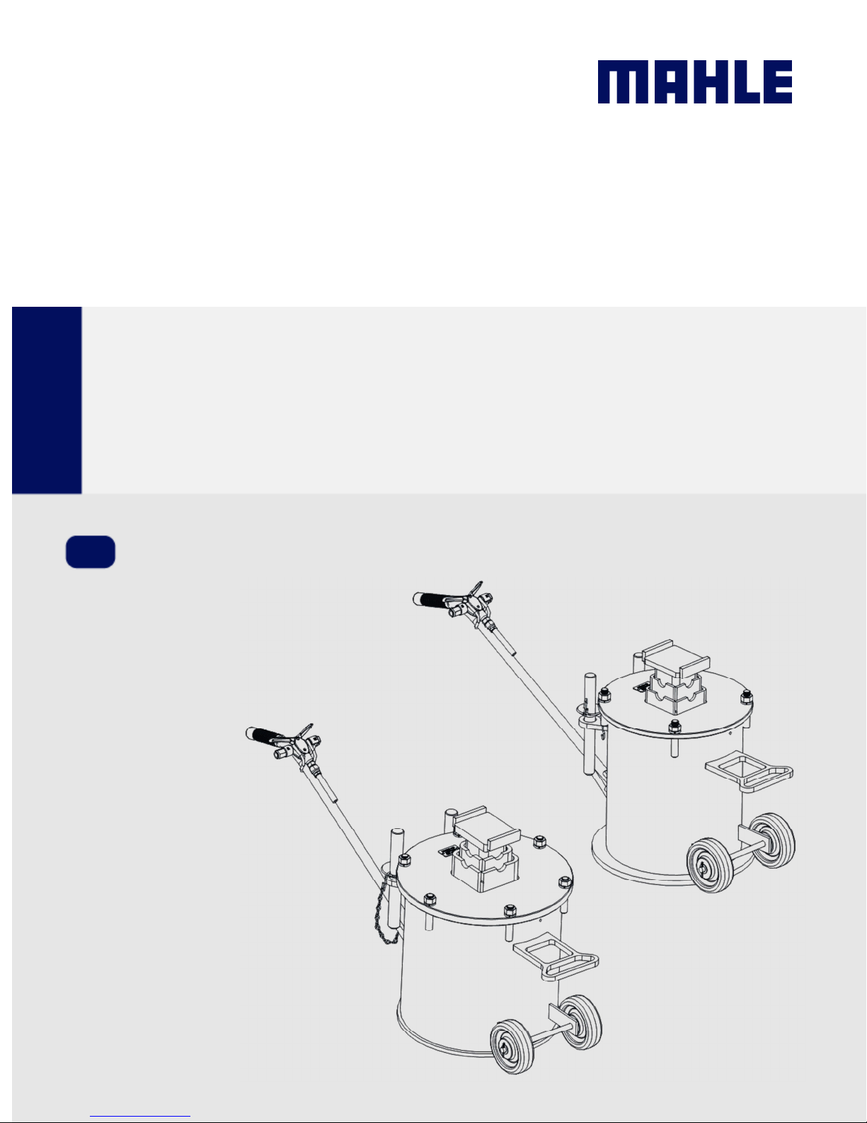
Operation Manual
Truck
Air Jack Stand
MAHLE CLS-10 &
EN
CLS-15

en | 2 |
CLS-10/CLS
-15
EVERY PERSON WHO OPERATES THIS
READ THIS MANUAL
EQUIPMENT NEEDS TO KNOW AND
UNDERSTAND ALL OF THE INFORMATION IN
THIS MANUAL – FAILURE TO DO SO COULD
RESULT IN SERIOUS INJURY OR DEATH.
CAREFULLY AND
RETAIN FOR YOUR
RECORDS

CLS-10/CLS
-
15 | 3 |
en
Contents
Contents
1. Safety Regulations ................................................ 4
1.1 Warnings ....................................................... 4
2. Foreword ................................................................ 5
2.1 From the manufacturer ................................. 5
3. Symbols Use .......................................................... 5
3.1 Signal words ................................................. 5
4. Responsibilities ..................................................... 6
4.1 Receiving inspection ..................................... 6
4.2 Owner and/or operator responsibilities ......... 6
5. Specifications ........................................................ 6
5.1 CLS-10.......................................................... 6
5.2 CLS-15.......................................................... 6
6. Product Description .............................................. 7
6.1 Component identification .............................. 7
7. Operation ............................................................... 8
7.1 Compressed air supply ................................. 8
To Operate a Single Jack ........................ 8
To Operate a Pair of Jacks ...................... 8
7.2 Preparation before operation ........................ 8
7.3 Identify a lift point on the vehicle and position
the jack ......................................................... 9
7.4 Raise the vehicle ........................................... 9
7.5 Support the vehicle. ...................................... 9
8. Maintenance and Inspection .............................. 10
8.1 Inspection – before each use ...................... 10
8.2 Maintenance instructions ............................ 10
9. Troubleshooting .................................................. 11
10. Maintenance Chart .............................................. 12
11. Notes .................................................................... 14

en | 4 |
CLS-10/CLS
-15
Safety Regulations
1. Safety Regulations
1.1 Warnings
Failure to follow all of these safety instructions can
lead to severe injury or death from a sudden loss of
the load. Contact the manufacturer at the numbers or
address printed on the back cover of this manual if
you have any questions.
Before using this jack, be sure you have read and
understood all of the instructions and warnings on the
on product labeling and in this owner’s manual. See
the section entitled “OWNER AND/OR OPERATOR
RESPONSIBILITIES” on page 6 of this manual for
more information.
Inspect the jack before each use. The jack must be
removed from service if damage is detected or if the
jack is subjected to an abnormal shock or load. See
page 10 of this manual for proper “INSPECTION –
BEFORE EACH USE.”
Inspect the work area before each use. Make sure
the jack and vehicle are located on a hard, level
surface capable of supporting the load.
Identify appropriate vehicle lift points before using
the jack. Lift only on areas of the vehicle specified by
the vehicle manufacturer. The lift point must be strong
enough to sustain the lifting force without damage to
the vehicle. The jack must remain in direct contact
with the floor and the lifting pad must be in direct
contact with the vehicle.
Make sure the lift point is securely cradled in the
center (i.e., between the “saddle ears”) of the lift post
saddle— Never lift a load with it resting on top of a
saddle ear of the lift post saddle. Always use the
factory-supplied lift post saddle to raise a load and
never use blocks or cribbing devices in conjunction
with this jack (only adapters and/or attachments
supplied by the manufacturer for this particular jack
can be used). Never place a hand or any other body
part between lift post saddle and vehicle.
Do not exceed the maximum lift height. Never use
more than one optional extension adapter with this
jack.
After lifting the vehicle, never allow any part of your
body to pass under it (and never begin work) until the
ram of the jack is properly pinned and the air is
exhausted. If the air is not exhausted and the jack is
not properly pinned, the jack may rise or drop
suddenly when a heavy object is removed from or
placed on the vehicle, which could cause dangerous
tilting or toppling of the vehicle.
Always use the jack as intended. Never modify or
alter the jack. If this jack does not have sufficient
capacity to lift a load, use a different jack with
adequate capacity. Never attempt to reposition or
rotate the jack or move, dolly, or drive the vehicle
while it is raised. Never use this jack to lower or
support a vehicle if the vehicle was raised using
another lifting device or devices. Do not attempt to
raise a partially-filled tanker or transport containing an
unrestrained load as a sudden load shift could cause
a dangerous tilting or toppling of the vehicle. Never
throw the jack or allow it to fall from an elevated
position, such as from a truck bed.
CAUTION - Use of this jack around corrosive
materials, such as chlorides, will damage inside the
cylinder, causing leakage. SUCH USE INVALIDATES
WARRANTY.
Make sure the load does not exceed the rated
capacity of the jack. The maximum capacity of the
jack is printed on the capacity tag located on the
head plate of the jack.

CLS-10/CLS
-
15 | 5 |
en
Foreword
Immediate
or
injury.
impending
or
injury
Possible
injury
Possible
Possible property
2. Foreword
2.1 From the manufacturer
Thank you for your purchase. To complement the
offering of A/C, fluid and nitrogen service equipment,
MAHLE Service Solutions has partnered with Gray
Manufacturing to provide the highest quality hydraulic
and pneumatic equipment available for the professional
service technician. This equipment adheres to high
standards promised in the MAHLE guarantee including
the assurance of innovation and reliability that comes
with the Gray Manufacturing name. Please contact
MAHLE Service Solutions’ customer service at (800)
468-2321 or tech.mss@us.mahle.com with any
comments or questions.
3. Symbols Use
3.1 Signal words
Signal words call attention to a safety message or
messages, or a property damage message or messages,
and designate a degree or level of hazard seriousness.
Signal words used in this manual include:
Keyword
DANGER
WARNING
CAUTION
NOTICE
Probability of
occurrence
impending danger
Possible
danger
dangerous
situation
damage to
property
Severity of danger if
instructions not observed
Death
Death
Minor
damage
severe
severe

en | 6 |
CLS-10/CLS
-15
Responsibilities
Maximum Lift Height with
Maximum Lift Height with
4. Responsibilities
4.1 Receiving inspection
Before attempting to operate this equipment, thoroughly
read and understand this manual. Completely remove all
tape and packaging. Inspect the equipment immediately
upon delivery. If shipping damage is evident, inform the
delivering carrier immediately and contact the
manufacturer using the contact information on the back
cover of this manual.
4.2 Owner and/or operator responsibilities
The owner of this equipment must read these
instructions and maintain them for future reference and
for instructing any other users of the equipment. The
owner is responsible for keeping all warning labels and
instruction manuals legible and intact. Replacement
labels and literature are available from the manufacturer.
The owner must never authorize or allow anyone to use
this equipment until the operator has read and
understood the information in this manual and on the
accompanying labeling on the equipment itself.
5. Specifications
5.1 CLS-10
Model CLS-10 US units Metric units
Capacity (at 150 psi) 15,000 lb each 6,804 kg each
Capacity (at 200 psi) 20,000 lb each 9,072 kg each
Maximum Lift Height 37.38 in 94.9 cm
Optional Extension Adapter
Minimum Starting Height 17.88 in 45.4 cm
Pin Increment Positions 2.50 in 6.4 cm
Stroke 10 in 25.4 cm
Width 15 in 38.1 cm
Length 22 in 55.9 cm
Weight 139 lb 63 kg
52.38 in 133.0 cm
If this equipment is being used in an occupational setting
(or workplace), the employer should ensure that all
personnel working with and around the equipment know
of the risks associated with its use. Personnel involved in
the use and operation of this equipment shall be careful,
competent, trained, and qualified in the safe operation of
the equipment and its proper use when servicing motor
vehicles and their components. Safety information
provided with this equipment should be emphasized by
the employer and understood by each employee. The
employer must make this manual available to all
personnel using this equipment and all personnel must
read and understand the contents of this manual. If the
operator is not fluent in English, the manufacturer’s
instructions and warnings shall be read to and discussed
with the operator in the operator’s native language by
the employer, making sure that the operator
comprehends its contents and observes the proper
procedures for use of this equipment.
5.2 CLS-15
Model CLS-15 US units Metric units
Capacity (at 150 psi) 20,000 lb each 9,072 kg each
Capacity (at 200 psi) 30,000 lb each 13,608 kg each
Maximum Lift Height 38.25 in 97.2 cm
Optional Extension Adapter
Minimum Starting Height 18.75 in 47.6 cm
Pin Increment Positions 2.50 in 6.4 cm
Stroke 10 in 25.4 cm
Width 16.25 in 41.2 cm
Length 23.75 in 60.3 cm
Weight 194 lb 88 kg
53.38 in 135.6 cm
CLS-10/CLS
-
15 | 7 |
en
Product Description
6. Product Description
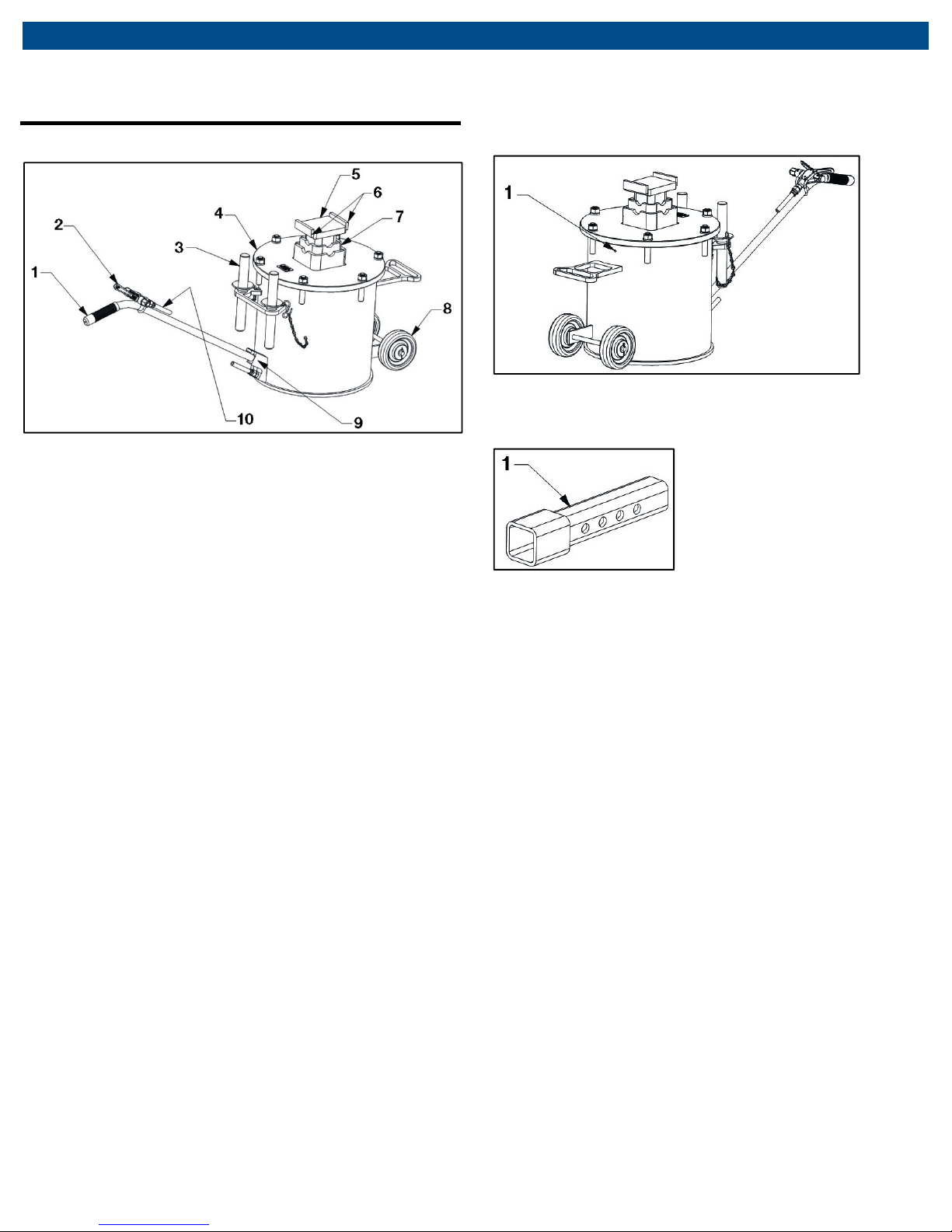
6.1 Component identification
Fig. 1: Top view
1 Handle
2 Air control valve
3 Stand pin
4 Head plate
5 Lift post saddle
6 Saddle ears
7 Piston rod
8 Wheel
9 Handle catch
10 Air line
Fig. 2: Drain hole location
1 Drain hole
Fig. 3: Extension adapter
1 Extension adapter

en | 8 |
CLS-10/CLS
-15
Operation
7. Operation
WARNING - This section discusses the appropriate and
safe methods for using the jack to raise and lower a
vehicle. Safe operation is not limited to simply raising
and lowering a vehicle - it also includes adequate
preparation before the vehicle is lifted. Failure to follow
all of the steps outlined in this section could result in
serious injury or death.
7.1 Compressed air supply
The jack requires a supply of compressed air to
operate.
To Operate a Single Jack
If the jack is being used as a single jack, the following
steps need to be completed prior to use:
1. Connect a quick coupler to the air control valve.
2. Attach an air hose with 200 psi maximum to the quick
coupler. The unit is now ready for use.
7.2 Preparation before operation
1. Make sure the vehicle load does not exceed the rated
capacity of the jack (see Specifications for the jack
model purchased).
2. Inspect the jack for signs of wear or damage (see
“Inspection Instructions” in Section 8). The jack should
be immediately removed from service if you detect any
abnormal conditions or signs of damage that suggest
the jack will not work properly or safely — When in
doubt, don’t use the jack!
If you see any signs of wear or damage, or if there is any
indication that the jack is not performing normally,
immediately take it out of service and contact customer
service at the address and number shown on the back
cover of this manual. NEVER use a jack that appears
damaged in any way.
3. Transport the jack to the work area by wheeling it. You
can push or pull the jack. Wheel the jack across smooth
surfaces only.
3. Actuate the air control valve lever and check that the
lift post raises and lowers as expected.
To Operate a Pair of Jacks
Because these jacks are often used in pairs, operating
the air control valves on both jacks simultaneously from
one airline offers advantages. To utilize a single airline,
assemble the air control valve from each jack according
to the Figure below or contact the manufacturer to
purchase a “Valve Tee Connection” kit (#8855-01009):
Fig. 4: Valve tee connection
Jolting caused by the wheels catching on uneven
surfaces can cause physical strain and personal injury.
4. Examine the work area. Use the jack only on hard, level
surfaces capable of safely supporting the load. The jack
must ALWAYS remain in direct contact with the floor.
NEVER attempt to lift from a polished or greasy floor.
Clear the surrounding area of personnel, tools,
equipment, or any other objects that would interfere with
the use of the jack. If these conditions cannot be met,
move the vehicle and jack to an area where the lift can
be performed safely.
5. Chock the vehicle’s wheels. When raising a vehicle from
one end, always chock the wheels that will remain on
the ground. Make sure at least two wheels of the vehicle
remain in contact with the floor at all times — NEVER
use the jack to raise all four wheels of the vehicle from
the floor.
6. Verify that the vehicle’s engine is not running before
raising it.

CLS-10/CLS
-
15 | 9 |
en
Operation
7.3 Identify a lift point on the vehicle and
position the jack
1. Identify a lift point on the vehicle that is capable of
supporting the load. Lift only on areas of the vehicle
specified by the vehicle manufacturer. The lift point must
be strong enough to sustain the lifting force without
damage to the vehicle.
2. If using only one jack to raise one end of the vehicle,
make sure that the jack is balanced side-to- side.
With one jack, it is extremely important to ensure the
load is level and stable during and after lifting. Loads
that are not balanced can result in tipping of the jack
which can result in loss of the load, leading to
personal injury, death, and/or property damage.
3. Position the unit(s) under the vehicle by using the
handle and place according to the vehicle
manufacturer’s recommended lifting points
7.4 Raise the vehicle
1. Raise the lift post manually on each jack to engage
the manufacturer’s recommended lift point. If using
two jacks as a pair, keep both lift posts at equal
heights. For each jack being used, insert the stand pin
in the nearest hole in the lift post so that the stand pin
fully engages both sides of the piston rod. This
position may not fully engage the lift point on the
vehicle until the unit is pressurized to lift the load.
7.5 Support the vehicle.
1. Make sure the vehicle is stable. If using two units,
make sure the vehicle is level. For each jack being
used, check that the stand pin is fully engaged with
the notches on both sides of the head plate. Slowly
release the air pressure to lower the vehicle so that it
is supported by the stand pins (and not the air
pressure from the jack). Fully discharge the air
pressure from the jack.
2. Before beginning work or placing any part of your
body under the vehicle, check one last time to ensure
the vehicle is stable and level (between a pair of jacks
or on a single jack).
3. When work is completed, reverse the process
described in this section to lower the vehicle.
2. If the lift post is not fully engaged with the lift point,
slowly apply air pressure until the lift post saddle
engages the lift points on the vehicle. Before raising
the vehicle, ensure that the lift post saddle is
positioned such that the lift point is cradled and
captured on both sides by the saddle ears on each
side of the lift post. Never lift a load with it resting on
top of an ear of the lift post saddle.
3. Apply air pressure to continue raising the vehicle. If
using a pair of jacks, use the air control valves to keep
the vehicle level while lifting. Once the proper height
has been achieved, insert the other stand pin through
the hole in the piston rod (for each jack being used),
such that the pins fully engage both sides of the head
plate when lowered.

en | 10 |
CLS-10/CLS
-15
Maintenance and Inspection
8. Maintenance and Inspection
WARNING - The jack must be inspected according to
the requirements of this section. Failure to properly
inspect the jack could lead to severe injury or death.
The owner must inspect or appoint a knowledgeable
person to inspect the jack for signs of corrosion,
damage and/or excessive wear. Contact the
manufacturer at the numbers and address printed on
the back cover of this manual.
All inspection and maintenance procedures must be
performed after the jack has been removed from
service. Failure to do this may result in personal injury
and/or property damage.
8.1 Inspection – before each use
Visual inspection should be made before each use of the
jack, checking for abnormal conditions. Regular
inspections should be made weekly for daily use or
monthly for intermittent use. Any jack that appears to be
damaged in any way, is found to be badly worn, or
operates abnormally shall be removed from service until
necessary repairs are made:
8.2 Maintenance instructions
WARNING - All inspection and maintenance procedures
must be performed after the jack has been removed from
service. Failure to do this may result in personal injury
and/or property damage.
The following procedures should be performed
periodically to properly maintain the jack:
Check that all controls operate freely. Wheels should
rotate freely.
All warning and capacity labels should be readable
and complete. Wash external surfaces of jack, labels,
and decals with a mild soap solution. Do not allow
water to run down the ram or the post and into the
cylinder area. If water or any other liquid enters the
cylinder, tilt the jack so the liquid can drain out the
drain hole (shown in the Component Identification
section).
Lubricate all rotating and sliding portions of the jack
monthly.
Inspect piston rod, lift post, and lift extension adapter
regularly and replace if they are cracked, chipped, or
show signs or excessive wear. Holes for the stand
pins must not be elongated or deformed.
Inspect stand pins for deformities or excessive wear.
Stand pins must be able to inset fully into the posts
and piston rod in all positions.
The piston rod should extend and retract smoothly
through its full range.
Inspect hoses for leaks or kinks. Inspect couplings for
damage or air leakage. Replace damaged or defective
hoses or couplings.
The jack must be removed from service and
inspected immediately if it is subjected to an
abnormal load or a shock load. If any irregularities or
problems are detected during an inspection, the jack
must be removed from service immediately and
repaired. Contact the manufacturer using the contact
information printed on the back cover of this manual.
Remember, if you have any doubt about the safe
condition of this jack, DON’T USE IT!

CLS-10/CLS
-15 | 11 |
en
Troubleshooting
9. Troubleshooting
This section is a list of potential problems and solutions.
If the solution listed fails to correct the problem, call the
manufacturer at the numbers and address printed on the
back cover of this manual. Please have the model
number, and serial number of your jack available. The
serial number is located on the capacity tag on the top of
the head plate.
Problem Cause/Solution
• Inadequate air pressure; Increase air
Fails to lift load
pressure but do not exceed 200 psi.
• Airline leaks; locate and correct leaks.
•
Overloaded; use larger-capacity jack.
Fails to hold load
• Stand pin not engaged.

en | 12 |
CLS-10/CLS
-15
Maintenance Chart
10. Maintenance Chart
Action Date Details
Receiving inspection
Person
responsible

CLS-10/CLS
-15 | 13 |
en
Maintenance Chart
Action Date Details
Person
responsible

en | 14 |
CLS-10/CLS
-15
Notes
11. Notes

CLS-10/CLS
-
15 | 15 |
en
Notes

670
-
90725
MAHLE Aftermarket Inc.
10 Innovation Drive
York, PA 17402 U.S.A.
Phone: (800) 468-2321
Fax: (717) 755-8304
E-mail: tech.mss@us.mahle.com
www.servicesolutions.mahle.com
 Loading...