

MAHLE ArcticPRO ACX2120H Operation Manual
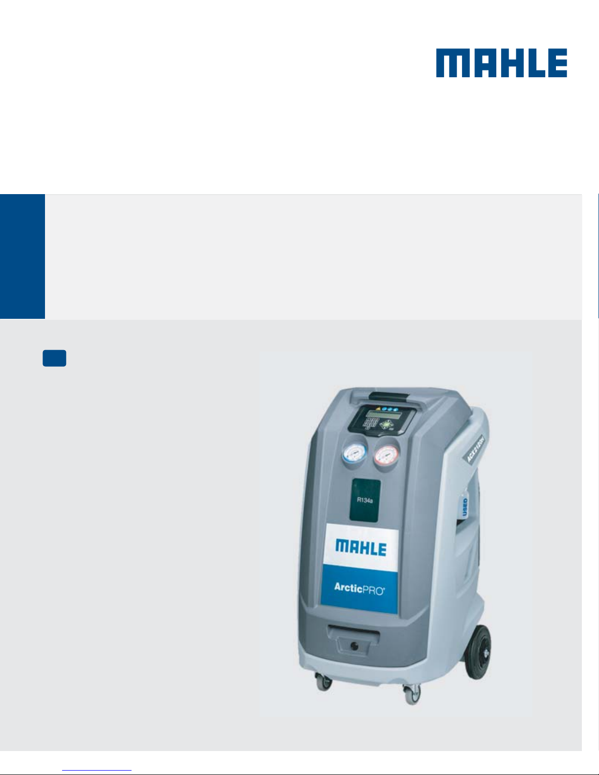
MAHLE ACX2120H
Operation manual
EN
A/C Service Equipment
2 | ACX2120H | en
Contents
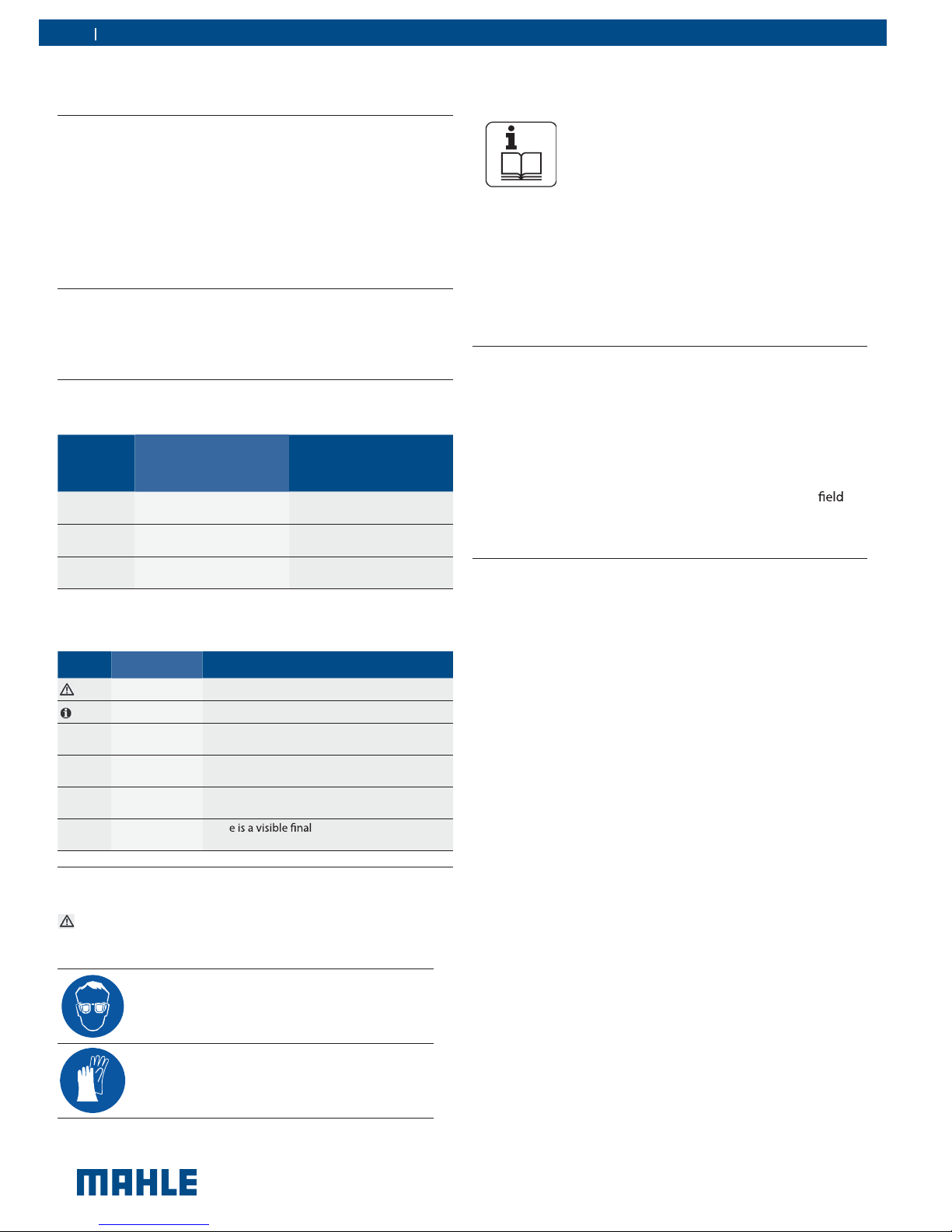
1. Symbols use 4
1.1 In the documentation 4
1.1.1 Warning notices—Structure and meaning 4
1.1.2 Symbols in this documentation 4
1.2 On the product 4
2. Important notes 4
2.1 User group 4
2.2 Agreement 4
2.3 Obligation of contractor 5
2.4 Safety regulations 6
2.4.1 ACX2120H 6
2.5 Safety devices 7
3. 8
Product description
3.1 Application 8
3.2 Scope of delivery 8
3.3 Description of unit 9
3.4 User interface 10
3.4.1 Selection and function keys 10
3.4.2 Input keys 10
3.4.3 Display screen 11
3.4.4 Main menu options 11
3.5 Unit features 11
3.5.1 EcoLOCK
3.5.2 Locking caster brakes 11
3.5.3 Power supply cable and switch 11
3.6 Functional description 12
4. 12
Technical features
5. Equipment installation 13
5.1 Unpacking ACX2120H 13
5.2 Load cell screw release 13
®
quick couplers 11
6. Commissioning 14
6.1 Connections and positioning 14
6.2 First start-up verification 14
7. Setup 15
7.1 ACX2120H 15
7.1.1 EcoLOCK 15
7.1.2 Recharge mode 15
7.1.3 Pressure check 15
7.1.4 Multipass 15
7.1.5 Report saving mode 15
7.1.6 Unit of measure 15
7.1.7 Clock adjustment 16
7.1.8 Setting language 16
7.1.9 Startup screen 16
7.1.10 Default setup 16
8. 17
A/C sevice preparation
8.1 Preliminary operations 17
8.2 Non-condensible gas discharge 17
8.3 Charge modes 17
8.3.1 Quick mode 17
8.3.2 Zero tolerance mode 17
9. 18
A/C system service
9.1 Automatic cycles 18
9.2 Manual cycles 19
9.2.1 Recovery process 19
9.2.2 Vacuum process 19
9.2.3 Recharge 20
9.2.4 Flushing (with optional accessories) 20
9.2.5 Pressure check 20
9.2.6 Hose emptying 20
© MAHLE
Maintenance
10. 21
10.1 Maintenance interval 21
10.2 Filling internal refrigerant cylinder 21
10.3 Self leak test 22
10.4 Cylinder pressure check 22
10.5 Cylinder refrigerant view 22
10.6 Pressure zero 22
10.7 Counters 22
10.8 Long life pump test 23
10.9 Vacuum pump oil change 23
10.10 Replace filter dryer 24
10.11 Multipass 24
10.12 System info 24
10.13 Software update 25
10.14 Refrigerant weight accuracy check 25
10.15 Printer maintenance 26
10.16 Periodic checks 26
11. 27
Spare parts
Disposal
12. 27
12.1 A/C Service unit disposal 27
12.2 Recycled material disposal 27
12.3 Packaging disposal 27
|
ACX2120H | 3
en
Troubleshooting
13. 28
13.1 ACX2120H 28
14. 30
Maintenance forms
14.1 Vacuum pump oil change 30
14.2 Filter dryer change 32
14.3 Refrigerant load cell calibration check 35
14.4 Other checks/maintenance/repairs 37
Notes
15. 39
© MAHLE
4 | ACX2120H | Important notesen
1. Symbols use
1.1 In the documentation
1.1.1 Warning notices - Structure and meaning
Warning notices warn of dangers to the user or people in the
vicinity. Warning notices also indicate the consequences of the
hazard as well as preventive action. Warning notices have the
following structure:
Warning
symbol
The key word indicates the likelihood of occurrence and the
severity of the hazard in the event of non-observance:
Key word Probability of
DANGER Immediate impending
WARNING Death or severe injury
CAUTION Minor injury
KEYWORD - Nature and source of hazard!
Consequences of hazard in the event of failure
to observe action and information given.
X Hazard prevention action and information.
occurrence
Death or severe injury
danger
Possible impending
danger
Possible dangerous
situation
Severity of danger
if instructions not
observed
2. Important notes
Before start up, connecting and operating MAHLE
products it is absolutely essential that the Original
instructions/owner’s manual and, in particular, the
safety instructions are studied carefully. By doing
so you can eliminate any uncertainties in handling MAHLE prod ucts and thus associated safety risks upfront; something which
is in the interests of your own safety and will ultimately help avoid
damage to the device. When a MAHLE product is handed over
to another person, not only the Original instructions but also the
safety instructions and information on its designated use must
be handed over to the person.
2.1 User group
The product may be used by skilled and instructed personnel
only. Personnel scheduled to be trained, familiarized, instructed
or to take part in a general training course may only work with
the product under the supervision of an experienced person.
All work conducted on pressurized equipment may be performed
by persons with sucient knowledge and experience in the
of refrigeration, cooling systems and coolants and, also be aware
of the risks involved in the use of pressurized devices.
2.2 Agreement
1.1.2 Symbols in this documentation
Symbol Designation Explanation
t
t
1.
2.
X
Ö
¨
Attention Warns about possible property damage.
Information Practical hints and other useful information.
Multi-step
operation
One-step
operation
Intermediate
result
Final result Ther
Instruction consisting of several steps.
Instruction consisting of one step.
An instruction produces a visible intermediate result.
result on completion of
the instruction.
1.2 On the product
Observe all warning notices on products and ensure they
m
remain legible.
X Wear protective goggles.
X Wear protective gloves.
By using the product you agree to the following regulations:
Copyright
Software and data are the property of MAHLE or its suppliers
and protected against copying by copyright laws, international
agreements and other national legal regulations. Copying or sell ing of data and software or any part thereof is impermissible and
punishable; in the event of any infringements MAHLE reserves
the right to proceed with criminal prosecution and to claim for
damages.
© MAHLE
Important notes |
ACX2120H | 5
en
Liability
All data in this program is based—where possible—on manufacturer and importer details. MAHLE does not accept liability for the
correctness and completeness of software and data; liability for
damage caused by faulty software and data is ruled out. Whatever
the event, MAHLE liability is restricted to the amount for which
the customer actually pays for this product. This disclaimer of
liability does not apply to damages caused by intent or gross
negligence on the part of MAHLE.
Warranty
Any use of non-approved hardware and software will result in a
to our product and thus to exclusion of any liability
and warranty, even if the hardware or software has in the mean
time been removed or deleted.
No changes may be made to our products. Our products may
only be used in combination with original accessories and original
service parts. Failing to do so, will render null and void all war
ranty claims.
This product may only be operated using MAHLE approved
operating systems. If the product is operated
system other than the approved one, then our warranty obligation
pursuant to our supply conditions will be rendered null and void.
Furthermore, we will not be held liable for damage and conse
quential damage incurred through the use of a non-approved
operating system.
using an operating
2.3 Obligation of contractor
The contractor is obliged to ensure that all measures geared
towards the prevention of accidents, industrial diseases, laborrelated health risks are taken and measures towards making
to work in are carried out.
Specifications for electrical systems (BGV A3)
Electrical engineering in Germany is subject to the accident
prevention regulations of the trade association "Electrical Plant
and Equipment as under BGV A3 (previously VBG 4)". In all
other countries, the applicable national regulations acts or de
crees are to be adhered to.
Basic rules
The contractor is bound to ensure that all electrical equipment
and operating material is set up, modied and maintained by
skilled electricians only or under the guidance and supervision
of a skilled electrician in accordance with electrical engineering
principles.
Furthermore, the contractor must ensure that all electrical equip
ment and operating material is operated in keeping with electrical
engineering principles.
If a piece of electrical equipment or operating material is found to
be defective, i.e. it does not or no longer complies with electrical
engineering principles, the contractor must ensure that the fault
is r
exists, also ensure that the electrical equipment or the electrical
operating material is not used.
immediately and, in the event that imminent danger
Tests (taking Germany as an example)
\
The contractor must ensure that all electrical systems and
equipment are tested by electrician or under the
guidance of
working order:
electrician to ensure they are in proper
— Before star
— After or repair before starting for the time.
— At given intervals. Set intervals such as to ensure that
faults that can be expected to occur are determined in
good time.
\
The test is to take the electrical engineering principles relating
hereto into account.
\
Upon request of the trade association, a test manual is to be
maintained into which specic entries are made.
© MAHLE
6 | ACX2120H | Important notesen
2.4 Safety regulations
2.4.1 ACX2120H
Always carefully study and follow all the safety regulations before
using the MAHLE product.
Avoid all skin contact with the refrigerant. The low
lead to frostbite. Should refrigerant come into con
tact with the skin, remove any moistened clothing
immediately and rinse the area of skin
generous amounts of water.
Avoid all skin contact with the UV dye. Should UV dye come
into contact with the skin, remove any moistened clothing
immediately and rinse the area of skin ted with generous
amounts of water.
R134a is colorless, with weak characteristic smell and heavier
than air. It may
provide for
leave the workshop.
Never inhale refrigerant, dye and oil vapors. The
vapors can irritate the eyes, nose and respiratory
system. If liquid refrigerant or UV dye comes into
contact with the eyes, rinse them thoroughly with
water for 15 minutes. Then obtain medical attention
even if no pain is felt.
into repair pits. Should refrigerant escape,
ventilation (particularly in repair pits) and
Never swallow UV dye. Should it be swallowed inadvertently,
never attempt to induce vomiting. Drink generous amounts of
water and obtain medical attention.
Before connecting the ACX2120H to a vehicle air condition
ing system or an external refrigerant bottle, make sure the
quick-release couplings are not leaking. Only ever use external
refrigerant bottles provided with safety valves and cer
inline with the applicable standards.
Before switching the ACX2120H, make sure all charging
and drainage operations have been completed. This prevents
damage to the unit and reduces risk of refrigerant escaping
into the environment.
Never use compressed air with R134a. Certain mix tures of air and R134a are highly mmable. Such
mixtures are a potential hazard and may lead to
explosions and thus cause damage or injury.
ted with
re or
Refrigerant extracted from a vehicle air conditioning system
may be contaminated with moisture, lubricant, dirt and traces
of other gases.
If the refrigerant has been contaminated by being mixed with
other gases, remove the contaminated refrigerant and add
fresh R134a before using the ACX2120H for A/C service.
R134a is not to be used in areas in which there is a danger
of explosion. Fire, open
Welding and soldering are not permitted.
The ACX2120H unit should not be exposed to excess moisture
or be operated in wet areas.
R134a is not to be mixed with other refrigerants. The mixing of
refrigerants could damage the vehicle air conditioning system.
If high-voltage components or high-voltage wires are
handled incorrectly, there is a risk of fatal injury from
high voltage and the possible transmission of current
through the body.
and smoking are prohibited.
De-energizing is only to be performed by a electri
cian, a
power systems engineer.
electrician for tasks (hybrid) or a
Work on vehicles with high-voltage components is only ever
to be performed in a safe, de-energized condition by persons
with the minimum
work".
"Trained to perform electrical
Even after deactivating a high-voltage vehicle electrical sys
tem, the high-voltage battery may still be live.
Operating condition cannot be established from any running
noise, as the electric machine is silent when stationary.
In gear positions "P" and "N" the engine or electric motor
may start spontaneously depending on the charge of the
high-voltage battery.
Never open or damage high-voltage batteries.
On vehicles that have been in an accident, never touch highvoltage components or exposed high-voltage wires before
deactivating the high-voltage vehicle electrical system.
The ACX2120H must be constantly monitored when in opera
tion. Never leave the ACX2120H unattended when in operation.
Vehicle A/C service using the ACX2120H must be prepared
and implemented such that the vehicle air conditioning system
circuit does not have to be opened (for example by removing
the radiator or engine).
Position the ACX2120H on all four wheels on a vibration-
proof surface so that proper operation of the scales is guaranteed.
The ACX2120H can be secured in position by locking the
caster brake.
© MAHLE
Important notes |
ACX2120H | 7
en
The ACX2120H must always be transported in its operating
position. Never lay the ACX2120H on its side, as oil could
then escape from the vacuum pump or the built in compres sor could be damaged.
There are no additional safety systems for protecting the
ACX2120H against damage resulting from natural catastro phes.
Never remove any components from inside the ACX2120H
except for maintenance or repair purposes.
Follow the pertinent legal regulations or directives to ensure
safe handling of pressurized devices.
We recommend calibrating the scales at least once per year.
Contact customer service for calibration of the scales.
The ACX2120H must be subjected to regular maintenance by
service personnel or authorized agents to ensure the safety
of the unit.
Disconnect power before performing any maintenance or
service to unit.
Never perform any maintenance work which is not expressly
recommended in this manual. Contact customer service if
components have to be replaced other than in the course of
maintenance work.
ACX2120H must be connected to a properly grounded electri -
cal connection.
If there is damage to the ACX2120H, terminate usage imme -
diately and contact customer service.
The service hoses and service quick-release couplings must
be regularly checked for wear and replaced if damaged.
The ACX2120H must be operated in an environment cor-
responding to the directive BGR 157 with respect to the
exchange of air.
Observe local laws or directives as to ensure the safety of the
pressurized device.
For safety reasons it is advisable to use a residual current
operated circuit breaker (r tions:
Parameters
Rated voltage 110 VAC ± 10%
Rated frequency 50/60Hz
Rated current 10A
Rated tripping current 30mA
Tripping switch C
2.5 Safety devices
Description Function
Pressure switch Switches the compressor if the normal operat -
ing pressure is exceeded.
Safety valve The safety valve opens if the design pressure is ex-
ceeded.
Circuit breaker Interrupts the power supply if overcurrent is applied
to the ACX2120H .
Vents The ACX2120H is provided with vents in the bottom
of the housing to ensure the exchange of air even
© MAHLE
8 | ACX2120H | Product descriptionen
3. Product description
3.1 Application
ACX2120H is suitable for vehicles with a conventional engine as
well as for hybrid and electric vehicles. ACX2120H features all the
functions required for vehicle A/C service.
The following functions can be implemented:
Refrigerant recovery and recharging.
Vacuum generation.
Flushing.
m The ACX2120H can only be operated with R134a. The
ACX2120H is not to be used for service work on vehicles
with air conditioning systems employing refrigerants other
than R134a, as this will cause damage. Prior to A/C service
check the type of refrigerant used in the vehicle air condition ing system.
3.2 Scope of delivery
Description
Service hose (high pressure)
Service hose (low pressure)
Quick-release coupling (high pressure)
Quick-release coupling (low pressure)
Used oil bottle
Original instructions
Adapter (external bottle) - US Acme 1/2
Calibration check weight
© MAHLE
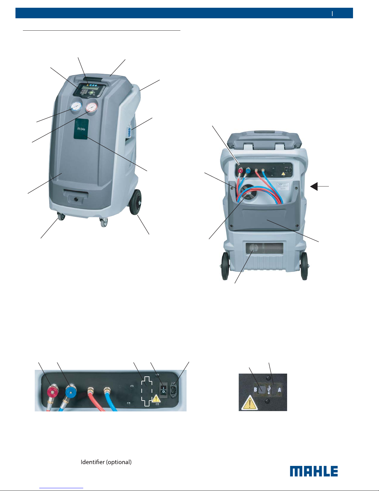
3.3 Description of unit
Product description |
ACX2120H | 9
en
3
2
4
1
5
10
SEE FIGURE A
(SEE BELOW)
6
11
7
1
SEE
FIGURE B
(SEE BELOW)
8
9
2
Fig. 1: Front Left View
1. Rear Handle
2. Tool Tray
3. LCD Display
4. Keypad
5. Low Pressure Gauge
3
6. High Pressure Gauge
7. Front Cover
8. Locking Caster
9. Rear Wheel
10. Used Oil Bottle
11. Printer (optional)
12 354
4
Fig. 2: Rear View
1. Service Hoses
2. Fan
3. Vent
4. Hose Storage
2
1
Fig. A: Rear Connection View
1. High Side Parking Coupler
2. Low Side Parking Coupler
3. Power Switch with circuit breaker
4. Power Cord Connector
5.
Fig. B: USB Ports
1. USB Type B (device port to PC)
2. USB Type A (USB memory stick port)
© MAHLE
10 | ACX2120H | Product descriptionen
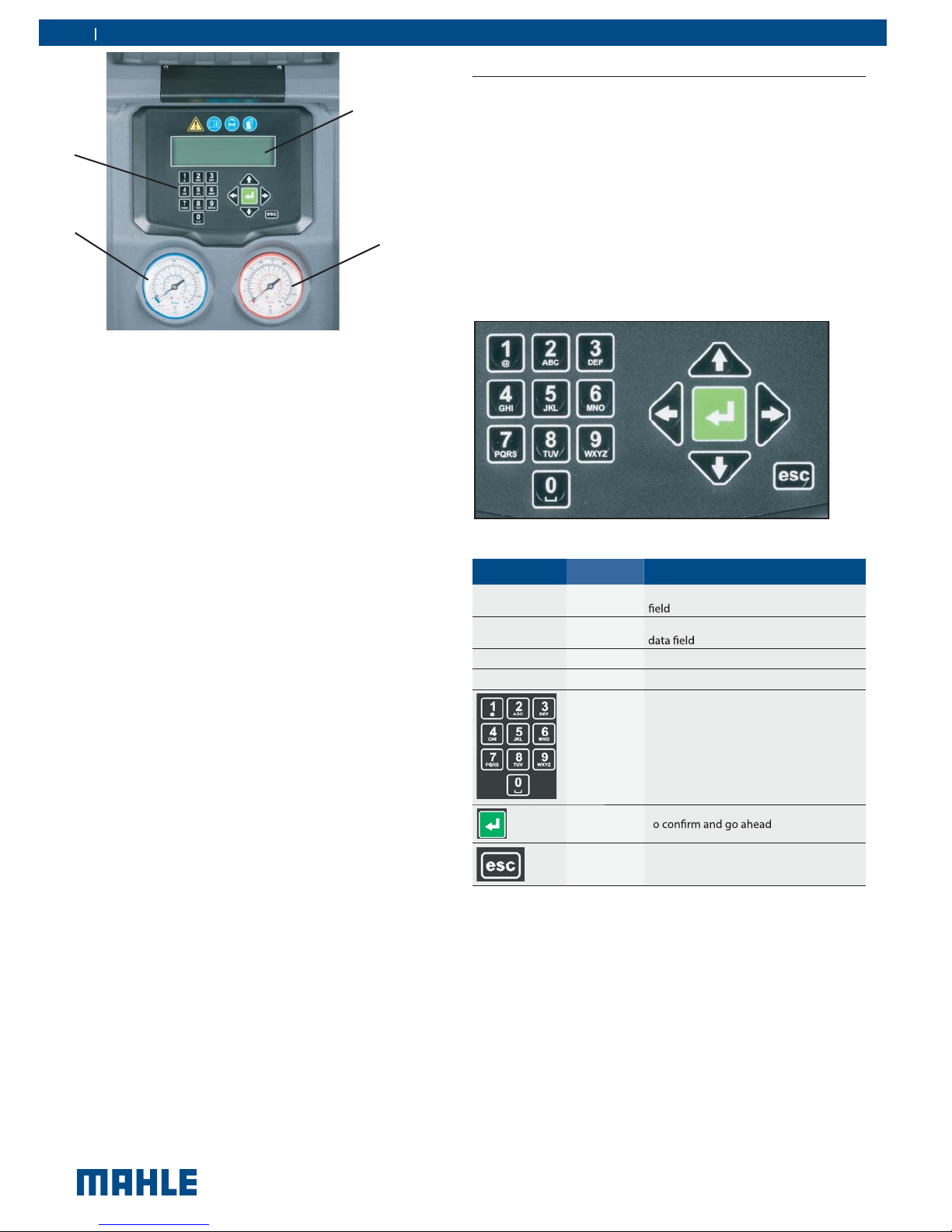
3.4 User interface
3
3.4.1 Selection and function keys
4
All settings, controls and service functions are available in the
pages shown on the LCD display. Data entry and moving of
the cursor is controlled by the keypad. The LCD displays the
2
1
Fig. 4: Display and operating unit
1
High-pressure gauge
2
Low-pressure gauge
3
LCD display
4
Keypad
service equipment's status, the progress of A/C system service and any alarms/error messages. When a button is pressed,
a beep sounds.
The following buttons are available:
The pressure gauges (Fig. 4, Pos. 1, 2) of the display and operat
-
ing unit are used to monitor the pressure during the individual
vehicle A/C service phases. The status of the various service
phases during maintenance is displayed on the LCD screen
(Fig. 4, Pos. 3).
The menu selection and necessary entries are made by way of
the keypad (Fig. 4, Pos. 4) integrated in the panel.
If a situation arises where the unit software requires updated,
MAHLE has a USB stick available for updating the ACX2120H
software. The USB stick can be inserted in the USB socket to
perform updating of the rmware/software.
Fig. 5: ACX2120H keypad
Keys Name Function
©
ª
§
¨
Up
Down
Left Arrow to decrease data value
Right Arrow to increase data value
Keypad/
Input Keys
Enter T
Escape To interrupt the operation in progress
To move up in the menu options or data
To move down in the menu options or
To enter a text with numbers and/or char acters. To enter letters/symbols, push
key multiple times to select one of the let ters available under that key - just as the
keyboard of a phone to compose SMS.
© MAHLE
3.4.2 Input keys
The input keys can be used to enter letters, numbers and special
characters in the input boxes. If a key is pressed several times
in succession in the input box, all the characters which can be
used for this are displayed.
Product description | ACX2120H | 11 en
3.4.3 Display screen
When unit loads, the total refrigerant weight screen will be dis played. Press to go to main menu as displayed in Fig. 6.
To select a function in the menu, press the © or ª ot llorcs ot
name of the desired function. The text name will blink once high lighted, then press the green ENTER key to select.
The menu moves up/down one line for every push of the © or
ª key.
A down arrow will appear in the lower right corner of the screen
as an indication that more menu option are available below
what is displayed on the current screen.
Fig. 6: Main menu screen
If you need to enter free text, the numerical keypad can be used.
The keyboard works like a keyboard of a phone to compose
SMS: press some times to select one of the letters available
under that key.
3.4.4 Main menu options
The main menu of the graphical user interface allows user to
select the following functions:
ACX2120H
3.5 Unit features
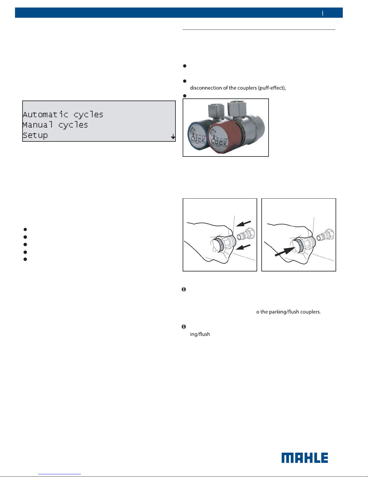
3.5.1 EcoLOCK® quick couplers (optional)
EcoLOCK
mated procedure in the software enables to:
Fig. 7: EcoLOCK® couplers
To connect the coupling, position the coupling on the parking
coupler, pull back the knurled section of the coupling element
and press carefully onto the connection (Fig. 8).
®
is the intelligent coupler, that with the suitable auto -
reduce the amount of non-condensible gases formed inside
the cylinder,
avoid the refrigerant (loss) dispersion in the air during the
check possible Schrader valve leaks before disconnection.
Automatic cycles
Manual cycles
Setup
Maintenance
Service
Each of the menu options will be described in detail later in the
manual.
Fig. 8: Fastening quick release coupling
t The service quick-release couplings are connected to the
service connections of the vehicle air conditioning system
during A/C service. When not in use, the service quick-release
couplings can be connected t
t To remove the service quick-release couplings from the park -
coupler, press the coupling slightly towards the connection and carefully pull the knurled section back to unfasten
it from the coupler.
3.5.2 Locking caster brakes
Rolling of the ACX2120H can be prevented by locking the caster
brakes (Fig. 1, Pos. 8) at the front wheels.
3.5.3 Power supply cable and switch
The power supply cable is connected to the main power input.
When not in operation, the power supply cable can be disconnected and hung on the handle. The ACX2120H is switched on
by toggling the rocker switch to the on position.
© MAHLE
12 | ACX2120H | Technical featuresen
3.6 Functional description
The refrigerant recovered from the air conditioning system passes
through the combo
moisture.
The purpose of the vacuum pump is to generate a vacuum in
the air conditioning system which removes excess moisture and
to detect possible leaks in the vehicle air conditioning system.
Used oil is separated from the recovered vehicle refrigerant and
drained into the used oil bottle.
The vehicle air conditioning system is partly
UV dye to facilitate the detection of leaks in the event of damage
to the vehicle air conditioning system.
The refrigerant in the internal refrigerant bottle is used for
the vehicle air conditioning system.
The purging unit for the non-condensable gases, consisting of
a temperature sensor, pressure sensor, coil and
takes
when the internal refrigerant bottle pressure is higher
than the saturation pressure.
ter to remove suspended particles and
lled with
always
4. Technical features
Description
R134a tank capacity 12L
Service pressure 400PSI
Maximum content 22lbs
Method to weigh gas content Load cell
Recovered oil container 250ml
Vacuum pump 2CFM dual stage
Vacuum pump oil quantity 250ml
Compressor capacity 0.87cu in/14cc
Dr
ter 75kg of recovered R134a
Non-condensible gas purge Automatic via solenoid valve
HP and LP taps Automatic
Display LCD monochrome FSTN 240x64 dots
Keypad Membrane
Software updating USB type A or USB type B direct con -
Printer (optional) Thermal, 24 columns
All functions Automatic and manual
Recycling mode Single or multipass
Memory for customized cycles 100 records
Flushing With integrated solenoid valves
System pressure diagnostics Manual and automatic
Dr
ter replacement alarm Active
Vacuum pump oil replacement
alarm
Full/empty tank check alarm Active
Full oil container check alarm Visual
Empty oil container alarm Visual
Dimension HxWxD 119 x 74 x 74 cm
Dry weight 98kg
Power supply frequency 60Hz
Voltage 120VAC, 1 phase
Total max load 7.5A
Overcurrent protection 12A (circuit breaker)
Operating temperature 50-122°F
Humidity 10-90%RH (non condensing)
Storage temperature and hu midity
Max operating altitude 6562ft
Pollution degree 2
Water degree 0
Cer
nect to PC
Active
-13 to 50°F
10-90%RH (non condensing)
SAE J2788
UL1963
CAN/CSA STD C22.2 NO. 120-M91
© MAHLE
 Loading...