


EN | 1 | ACX150/250 | CONTENTS
1 CONTENTS
1 CONTENTS 1
2 General instructions 3
2.1 General notes 3
2.2 General instructions 3
2.3 Manufacturer identification 3
3 Safety conditions 3
3.1 Personal safety information 3
3.1.1 Definitions 3
3.1.2 Personal safety
information 4
3.2 Important information on
service equipment safety 7
3.3 Safety devices 7
4 Layout of the manual 7
4.1 Use of the manual 7
4.2 Symbols 8
4.2.1 Safety 8
4.3 Glossary 8
4.4 Guidelines for the handling of
refrigerant 9
4.4.1 Precautions for
refrigerant storage 9
4.4.2 Conditions of refrigerant
and system 10
4.4.3 Recycling capacity 10
5 Product description 10
5.1 Application 10
5.2 Scope of delivery 10
5.3 Description of the unit 10
5.4 User interface 11
5.4.1 Main menu 12
5.5 E³ connect quick couplers 13
6 Technical features 14
7 Installation 15
7.1 Equipment installation 15
7.1.1 Unpacking ACX150/250
15
REFRIGERANT SCALE SCREW
RELEASE 16
8 Commissioning 16
8.1 Connections 16
8.1.1 Positioning and
connection 17
8.2 Initial verification 17
8.3 New oil bottle filling 18
8.4 UV dye bottle filling 19
9 Setup 19
10 A/C system charge 20
10.1 Preliminary operations 20
10.2 Non-condensable gas
discharge 21
10.3 Quick mode and zero
tolerance charge mode 22
11 Automatic cycle 22
11.1 Automatic cycle data loading
22
11.2 Automatic cycle data setting 23
12 Manual cycle 24
12.1 Recovery 24
12.2 Vacuum 24
12.3 Charge 24
12.4 Flushing (with optional
accessories) 25
12.5 Hoses drain 25
13 Special test 25
13.1 AC performance test 25
13.2 Refrigerant clean 26
14 Maintenance 26
14.1 Report exporting 26
14.2 Internal cylinder fill 26
14.3 Self leak test 27
14.4 Cylinder refrigerant view 27
14.5 Air purge 27
14.6 Pressures zero 27
14.7 Counters 28
14.8 E³ pump - pump oil change 28
14.9 Dryer filter replacement 29
14.10 System info 30
14.11 System update 30
11.1.1 Database 22
11.1.2 Last cycle 22
11.1.3 My database 23
11.1.4 Direct input 23
11.2.1 Electric Compressor
Function 23
14.8.1 Oil pump visual check 29
© MAHLE

14.12
Maintenance of printer
31
14.13 Periodic checks 31
14.14 Refrigerant type
replacement 32
15 Disposal 32
15.1 A/c service unit disposal 32
15.2 Recycled materials disposal 32
15.3 Packaging disposal 32
16 Spare parts 32
EN | 2 | ACX150/250 | CONTENTS
© MAHLE

EN | 3 | ACX150/250 | General instructions
2 General
instructions
2.1 General notes
All rights reserved.
This manual may not be reproduced, in
part or entirely, either in printed or digital
form.
It may be printed out solely for use by the
user and operators of the equipment to
which it refers.
MAHLE and resources used for the
drawing up of this manual will not be held
responsible for the incorrect use of the
manual while they guarantee that
information in the manual have been duly
checked.
The product can be subject to changes
and improvements. MAHLE reserves the
right to change without notice the
information contained in the manual.
Authorised MAHLE Centre, in
accordance with the practice described
in Chapter 12 of this manual.
This equipment is intended solely for use
by professionally trained operators
familiar with the basics of refrigeration,
refrigeration systems, refrigerants and the
hazards associated with pressurised
equipment.
Careful reading of the present manual by
the owners, the users and the operators
is required for a correct and safe use of
the tool.
The user shall not be entitled to open the
product since maintenance operations
are reserved to the authorised service
centre.
2.3 Manufacturer
2.2 General instructions
Pressure equipment undergoes checks
before commissioning and periodical
checks during operation, in compliance
with rules and law provisions in force in
the country where the tool is used.
The operator is responsible for operating
the equipment in conformity with local
legislation.
The equipment is designed for
recovering and recycling
R1234yf/R134a refrigerant fluid from
automotive A/C plant.
The equipment is intended to be used
by automotive and similar repair and
service workshops.
The switch between the two refrigerant
types, from R134a to R1234yf, can only
be performed by a technician of an
3 Safety conditions
3.1 Personal safety
3.1.1 Definitions
DANGEROUS AREAS:
Any area within or close to the equipment
implying risk for the safety and health of
exposed persons.
EXPOSED PERSON:
Any person completely or partially
standing in a dangerous area.
identification
The ACX equipment is manufactured by:
MAHLE Aftermarket GmbH
Service Solutions Europe
Pragstr. 26 - 46, 70376 Stuttgart,
Germany
Phone: +49 711 501-14003
information
© MAHLE
EN | 4 | ACX150/250 | Safety conditions
OPERATOR:
The person/s charged with operating the
machine for its intended purpose.
CLASSIFICATION OF OPERATORS
The operator can be classified according
to two main categories, which, in some
cases, refer to one single person:
The operator charged with the
equipment operation has the duty to:
o Start up and monitor the
machine's automatic cycle;
o Carry out simple setting
operations;
o Remove the causes of
equipment stop not implying
breakings of members but
simple operating anomalies.
Maintenance technician a technician
trained by an authorised MAHLE
centre, capable of working on the
machine’s mechanical and electrical
components with its guards open to
make adjustments and to service and
repair it.
USER
Body or person legally responsible for the
equipment.
3.1.2 Personal safety information
The MAHLE ACX 150/250 A/C service
station is particularly simple and reliable
due to its adjustments and functions.
When used correctly it presents no
hazard for the operator, provided he
observes the following general safety
instructions and that the service station is
regularly serviced (incorrect
maintenance/use compromise the
equipment's safety). Before operating the
service station for the first time, read
these instructions carefully. If any part of
the instructions is unclear, contact your
reseller or MAHLE.
This service station may be used by only
one equipment operator, familiar with A/C
and refrigeration systems and the hazards
associated with refrigerants and high
pressure equipment.
WORKPLACE: The station can work with
both R134a and R1234yf (the two
refrigerants cannot be stored within the
station at the same time).
Refrigerant R1234yf is defined as
flammable refrigerant.
Nonetheless, although refrigerant R134a
is not defined as flammable, mixtures of
air or oxygen with R134a may become
flammable under very particular
conditions.
The equipment must be operated
outdoor or in a well-ventilated location
(at least 1 air change per hour). The
workshop has to be equipped with
ventilation systems able to ensure air
change in every environment area or
carry out periodical ventilation by
opening the areas.
Use the equipment away from heat
sources or hot surfaces. The equipment
must not be used in explosion risk
environments (potentially explosive
atmospheres). Before using it, put the
equipment on a levelled plane and secure
position, blocking it with suitable wheel
stops.
Do not expose the tool to direct sunrays,
heat sources, rain and jets of water. Do
not smoke near the equipment and during
operations (keep at a distance of at least
1 m).
© MAHLE
EN | 5 | ACX150/250 | Safety conditions
The work area must be monitored by the
operator while the equipment is operating.
ATTENTION: R134a and/or R1234yf
refrigerant fumes/gases are heavier than
air and can gather on the floor or inside
cavities/holes and cause choke by
reducing the oxygen available for
breathing.
At high temperatures, the refrigerant
breaks down releasing toxic and
aggressive substances, harmful for the
operator and the environment.) Avoid
inhaling the system coolants and oils.
Exposure can irritate eyes and the
respiratory tract.
ELECTRICAL CONNECTION: Connect
the power cord solely to a mains supply
which conforms to the ratings on the
machine's nameplate (mounted on its
side). Make sure the mains socket is
grounded.
Maximum impedance allowed in the point
of connection to the mains shall comply
with standard EN 61000-3-11. Starting
currents can cause short voltage drops,
which may affect other equipments under
unfavourable conditions. If impedance in
the point of connection to the mains is
not compliant, this may lead to
interference so please consult the
electrical power network operator before
connecting the equipment.
Never use the service station with a
defective power cord or a different one
from that supplied with the machine. If
damaged, immediately have it replaced
with an original spare part or equivalent
by a MAHLE centre. Before opening the
service station, extract completely the
supply cable from the plug, or you can
get an electric shock.
Do not tamper with or bypass the safety
equipment and settings.
Do not leave the machine powered up
when not in use; shut off the power
supply before leaving the equipment
unused for a long time. Do not forget that
the tool (pressure tool) must always be
protected.
REFRIGERANTS AND LUBRICANTS PERSONAL SAFETY EQUIPMENT AND
PRECAUTIONS: The refrigerants and the
pressure cylinders have to be handled
with care, otherwise there will be possible
health risks.
The operator must wear safety glasses,
gloves and protective clothing suitable to
the work. Contact with the refrigerant can
cause blindness (eyes) and other physical
damages (freezing) to the operator. Avoid
contact with the skin; the refrigerant's low
boiling point (approx. –26 °C for R134a
and approx. -30 °C for R1234yf) can
cause freezing burns.
Further information about safety can be
obtained from the safety sheets of
lubricant and refrigerant producers.
Do not inhale refrigerant or oil vapour.
Keep away from the vent valves and
ventilation coupling, especially when noncondensable gas is being vented.
Never direct the quick couplings (taps)
towards your face or other persons or
animals.
© MAHLE
EN | 6 | ACX150/250 | Safety conditions
OTHER PROHIBITIONS AND USE
LIMITATIONS: Only use pure R134a or
R1234yf refrigerants, refrain from using
on vehicles containing other types of
refrigerants or mixtures of the two
refrigerants or other refrigerants.
Mixture with other types of refrigerant
produces serious damage to the
conditioning and cooling systems. Mixed
refrigerants have to be disposed of
according to the current regulations.
Never use ACX equipment with systems
containing compressed air; mixtures of
R134a or R1234yf with air or oxygen may
be potentially flammable.
Do not modify calibration of safety
devices. Do not remove seals of safety
valves and of control systems. Do not use
external tanks or other storage containers
that are not type-approved or without
safety valves.
Make sure the equipment's aeration and
ventilation ports are not obstructed or
covered while the equipment is operating.
HOSE CONNECTIONS: Hoses may
contain pressurised refrigerant. Before
changing the service couplers, check the
respective pressures in the hoses
(pressure gauge).
Before connection to a car A/C system, to
an external tank/cylinder, check that the
quick couplers are closed (unscrewed HP
and LP valves).
Scrupulously follow the instructions on
the equipment's display.
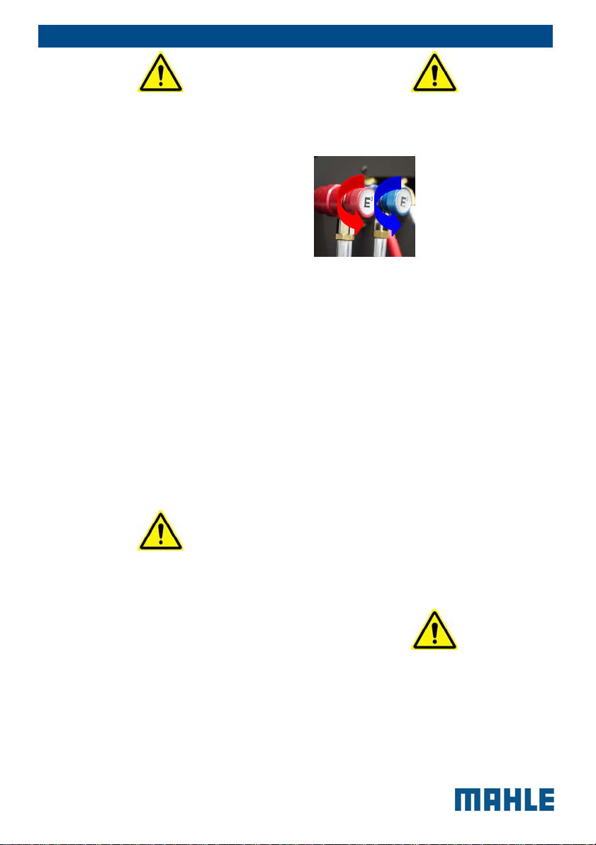
QUICK COUPLERS
CLOSING/OPENING:
Opening (connect to
the vehicle):
clockwise
Closing (detach from
the vehicle):
counter clockwise
MAINTENANCE/GENERAL CLEANING:
The equipment has to be serviced at the
intervals indicated by the equipment itself.
The service station maintenance has to
be performed according to the
procedures described in this manual and
to the current safety regulations.
Use only MAHLE original parts.
When the equipment requires the drier
filter and the vacuum pump oil to be
changed, you have to be careful in the
replacement.
A/C service station maintenance can be
carried out exclusively by a trained
operator or by a service man of a MAHLE
certified seller.
Do not use chemical agents for the
service station cleaning as they could
attack the material or the surface.
STOP FOR LONG PERIOD: Store the
equipment in a safe place, disconnected
from the mains, away from excessive
temperatures, humidity and the risk of
damaging impact.
Contact the Technical Service to run a
safety shutdown of the equipment, and if
© MAHLE

EN | 7 | ACX150/250 | Layout of the manual
scrapping the unit, to drain and recycle
the R134a or R1234yf refrigerant as
required by local legislation.
To resume operation, repeat the
installation (there is no need to register
the unit anew on the website) and run the
commissioning trials and regular
operational checks as required by local
legislation.
3.2 Important information
on service equipment
safety
When using the equipment, the following
operations are not allowed as they might
cause, under certain circumstances,
danger for persons and cause permanent
damage to the equipment itself.
- Do not remove or make
unreadable labels, signs
and/or dangers signs placed
on the equipment and in the
area nearby.
- Do not disable the unit's
safety equipment.
- The electrical system to
which the service equipment
is connected must be
configured as provided by
local legislation.
- Only operators or qualified
staff instructed or certified for
the equipment maintenance
can open the equipment. The
equipment contains parts
which can cause
electrocution: shut off power
to the equipment before
servicing/repairing it.
3.3 Safety devices
ACX 150/250 is equipped with the
following safety devices:
SAFETY PRESSURE SWITCH:
It stops the compressor in case
of excessive pressure.
SAFETY VALVE: The safety
valve opens when the pressure
inside the system reaches a
level higher than the fixed limits.
MAIN SWITCH: Switches the
equipment off by interrupting
the power supply. It is advisable
to pull the power cord plug out
of the mains socket in any case
before starting maintenance
work.
ANY TAMPERING WITH THE
ABOVE-MENTIONED SAFETY
DEVICES IS PROHIBITED.
Failure to observe any of the above
safety instructions voids the
equipment's warranty.
4 Layout of the
manual
4.1 Use of the manual
This manual is an integral part
of the equipment and must be
kept in the equipment's
immediate vicinity by the
purchaser
This manual shall accompany
the equipment in case this is
passed on to a new user.
© MAHLE
The content of this manual has
been drawn up in compliance
with the guide lines of the UNI
standard 10893:2000.
Diffusion, modification or use of
this manual for own aims is
forbidden.
The manual uses symbols which
call the reader's attention to
specific points to facilitate its
use.
It includes all technical,
operating, shutdown,
maintenance, spare parts and
safety information.
In case of doubts on the correct
interpretation of the instructions,
please contact our technical
service to obtain the required
clarifications.
Operations which are
potentially hazardous for the
operator are highlighted with
this symbol.
Such operations can cause
serious injury.
Operations requiring special
attention are highlighted with
this symbol.
Such operations shall be
carried out correctly to avoid
causing damage to objects or
to the surrounding
environment. This symbol also
highlights information to which
special attention must be paid.
Operations which require
careful reading of the manual's
instructions are highlighted
with this symbol.
EN | 8 | ACX150/250 | Layout of the manual
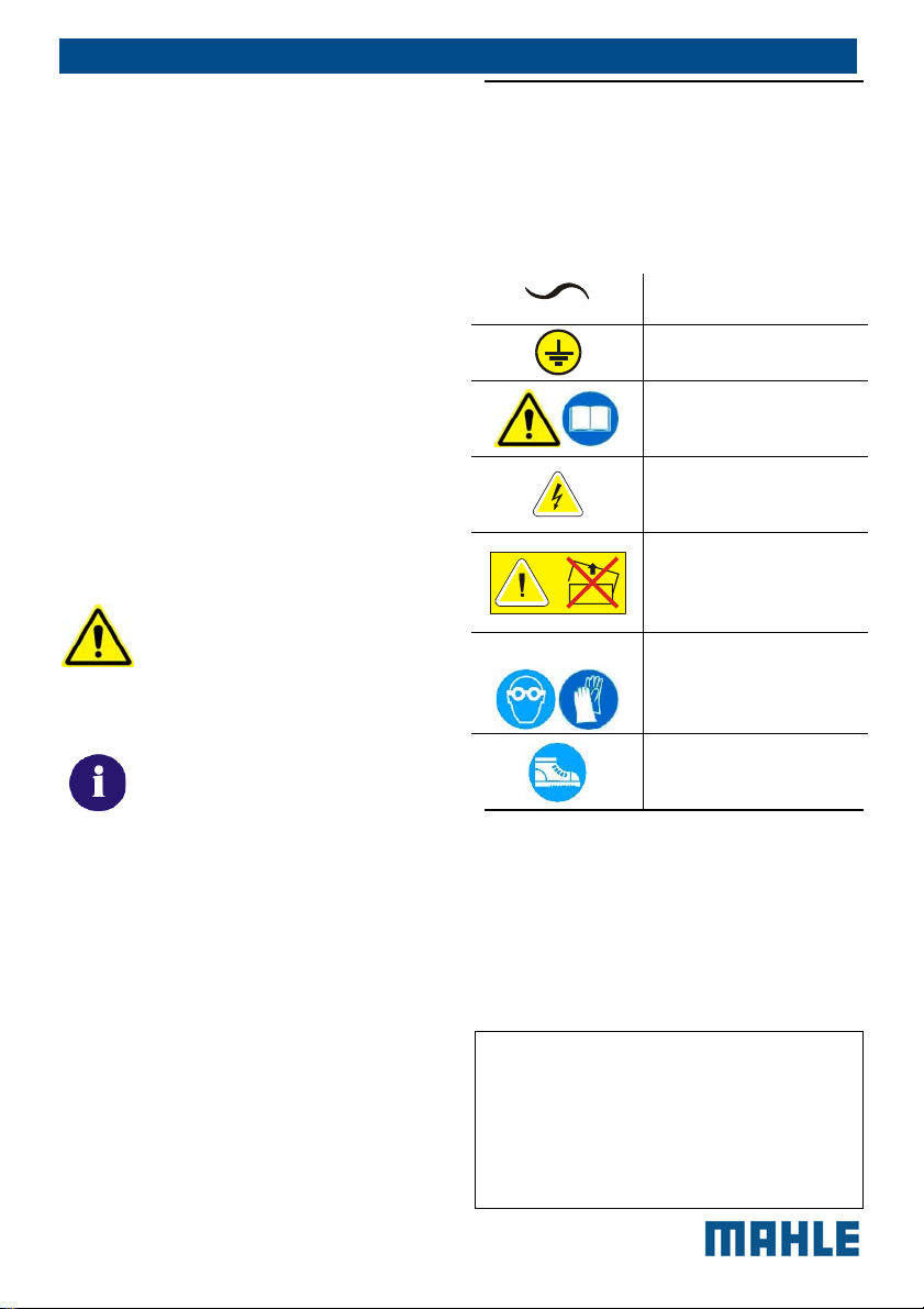
4.2 Symbols
This paragraph describes the safety
symbols which may be posted on the
service equipment.
4.2.1 Safety
ALTERNATING
CURRENT
SAFETY GROUNDING
CONSULT THE
INSTRUCTIONS
MANUAL
ATTENTION!
ELECTROCUTION
HAZARD
CAUTION !: DO NOT
REMOVE THE COVER
(maintenance
technicians only)
USE PROTECTIVE
GLOVES
WEAR PROTECTIVE
GOGGLES
USE ANTI-SMASH
SAFETY SHOES
4.3 Glossary
To make the reading of this manual
easier, we have prepared the list of the
most important technical terms used in
the manual.
Refrigerant: Refrigerant fluid used in
advanced motor vehicle A/C systems.
The following refrigerant fluids
may be used:
R-1234yf CH2CFCF3 2,3,3,3-
Tetrafluoropropene.
R-134a C2H2F4 - 1,1,1,2-
© MAHLE
EN | 9 | ACX150/250 | Layout of the manual
Tetrafluoroethane
A/C system: air conditioning system.
Equipment:
ACX 150/250
service
station for recovering, recycling, draining
and charging the A/C system.
External tank: Refrigerant bottle used to
fill the internal tank.
Internal cylinder: cylinder for refrigerant
storage.
System flushing: Cleaning phase for the
removal of possible polluting substances
from the A/C system or parts of it.
Non condensable gas: Refrigerant
stored in gaseous phase, including air
and nitrogen.
4.4 Guidelines for the
4.4.1 Precautions for refrigerant
Phase: Performance of a single function.
Cycle: Sequence of steps.
Recovery: Extraction of refrigerant from
the vehicle.
Recycling: Cleaning of refrigerant,
includes: separating out oils, removal of
non-condensable gas and
single/multiple pass through filters to
reduce humidity, acidity and particulate
content of the fluid.
Disposal: disposal of refrigerant for
storage followed by
The refrigerant removed from the A/C
system must be handled with care to
prevent or minimise the risk of mixing
with other refrigerants.
This machine is suitable for treating
R134a or R1234yf refrigerants,
individually (not simultaneously).
The external cylinders used to store the
refrigerants must be clearly marked to
prevent mixing different refrigerants.
Cylinders shall be free from oil or other
contaminants and clearly marked so as to
identify the refrigerant contained.
destruction/scrapping by an authorised
waste management centre.
Vacuum cycle: Draining out of a motor
vehicle A/C system and separation out of
condensed matter and humidity, using
only the vacuum pump.
Oil charge: Charge of oil into an A/C
system to ensure the correct charge as
specified by the vehicle's manufacturer.
Charge: filling of refrigerant into the A/C
system in the amount specified by the
manufacturer.
handling of refrigerant
storage
ATTENTION: when handling,
using and storing R-134a or R1234yf refrigerant and dealing
with emergency situations,
MAKE SURE to refer to the
product’s safety sheet.
GET THE SAFETY SHEET
FROM YOUR REFRIGERANT
SUPPLIER AND FOLLOW ITS
INSTRUCTIONS.
REFRIGERANT R1234YF IS
DEFINED AS FLAMMABLE
REFRIGERANT.
© MAHLE
4.4.2 Conditions of refrigerant
and system
The condition of the refrigerant is critical
to the operation of the vehicle's A/C
system. Running repairs properly
following failure or damage safeguards
the quality of the refrigerant itself
(particulates, acids and water).
4.4.3 Recycling capacity
The service equipment's filtering systems
must be replaced regularly (see
maintenance messages) to ensure
effective recycling.
EN | 10 | ACX150/250 | Product description
5 Product
description
5.1 Application
ACX150/250 is suitable for vehicles with a
conventional engine. ACX150/250
features all the functions required for
vehicle A/C service.
The following functions can be
implemented:
Refrigerant recovery and
recharging.
Vacuum generation.
Flushing.
5.2 Scope of delivery
Description
Service hose (high pressure)
Service hose (low pressure)
Quick-release coupling (high pressure)
Quick-release coupling (low pressure)
New oil bottle (2pcs)
UV dye bottle
Used oil bottle
Original instructions
Adapter for external bottle
connection
Hose Flushing Adapter
(built-in)
Safety goggles
Safety gloves
Dust cover
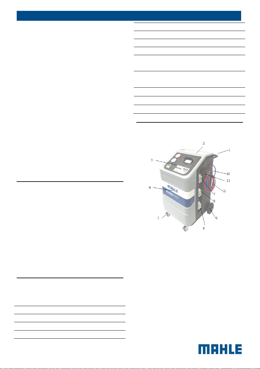
5.3 Description of the unit
Fig.1: Left-Front view
1
Rear handle and grip
2
Tool tray and storage
3
Display and operating unit
4
ACX150/250 front housing
5
Locking caster
6
Rear wheel
7
New oil bottle
8
UV dye bottle
9
Used oil bottle
10
Low-side parking
11
High-side parking
12
Service hose
© MAHLE
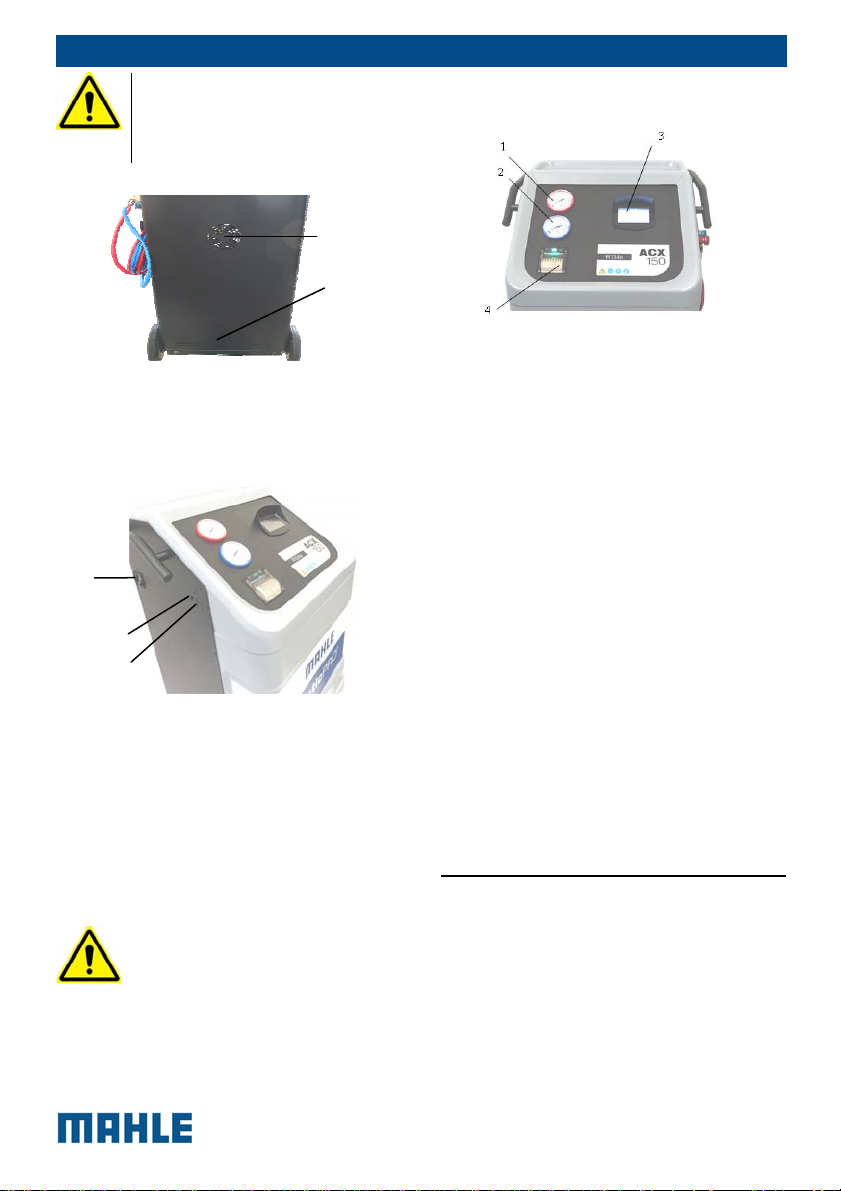
EN | 11 | ACX150/250 | Product description
DO NOT USE THE UNIT
UNLESS THE CHARGING
HOSES (HP – LP) ARE
CORRECTLY CONNECTED
1
2
Fig. 2: Rear view (detail)
1
Fan
2
Vents
1
2
3
Fig. 3: Right-front view (detail)
1
Power cord connector and
Power switch
2
USB type B (Device port to PC)
3
USB type A (Host port to USB
Memory Stick)
The USB type-A connector
can only be used with USB
2.0 portable memory devices
with Mass storage service for
reports export and station
update, or for connection to
MAHLE refrigerant identifier.
Do not connect other types
of devices, such as USB
keyboards or other units.
Fig. 4: Display and operating unit
1
High-pressure gauge
2
Low-pressure gauge
3
LCD Display with Touch screen
4
Printer
The pressure gauges (Fig. 4, Pos. 1, 2)
of the display and operating unit are
used to monitor the pressure during the
individual vehicle A/C service phases.
The status of the various service phases
during maintenance is displayed on the
multicolor LCD screen (Fig. 4, Pos. 3).
The menu selection and the necessary
entries are made by way of the touch
screen (Fig. 4, Pos. 3) integrated in the
LCD display. MAHLE supplies a USB
stick for updating the ACX150/250
software. If required, the USB stick can
be inserted in the USB type A socket
(Fig. 3, Pos. 4) to perform updating of
the firmware/software.
5.4 User interface
All settings, controls and service
functions are available on the touch
screen display. It also displays the service
equipment’s status, the progress of A/C
system service and any alarms and error
messages.
© MAHLE
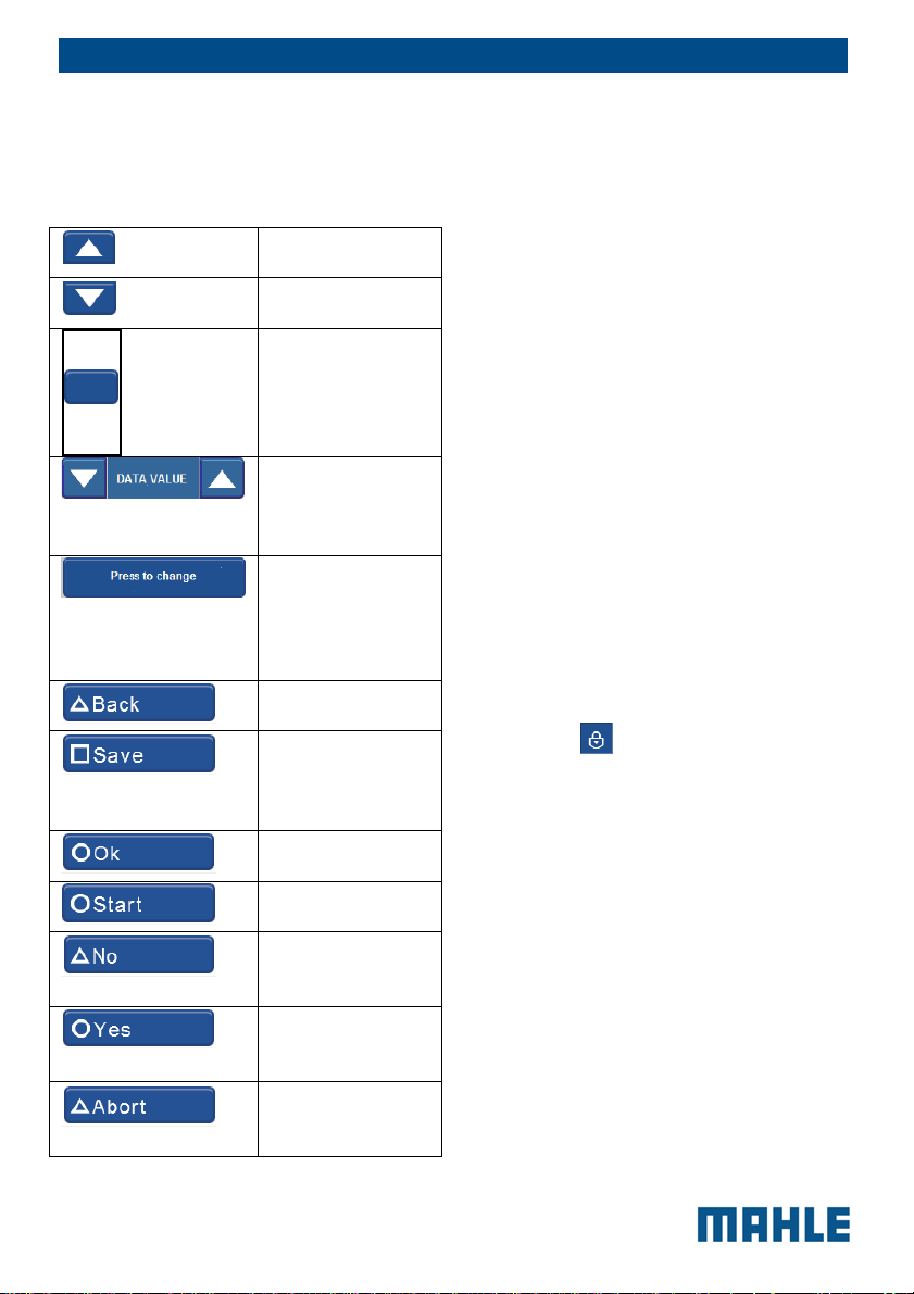
The touch screen is the basic operator
interface and can be operated with the
fingers.
When a button is pressed, a beep sounds.
The following functions keys are available:
To move up in the
menu options
To move down in
the menu options
Scroll bar to
move in the menu
options
Arrows to
decrease or
increase the data
value
To enter in the
data changing or
switching the
data to next
option
To return to the
previous page
To save the
programmed
cycle in a
personal memory
To confirm and to
go head
To begin the
cycle
To answer NO to
the displayed
question
To answer YES to
the displayed
question
To interrupt the
operation in
progress
EN | 12 | ACX150/250 | Product description
To select a function in the menu press the
text name of the function, the selection
occurs when the finger is released, the
selected entry is pointed out with a
different colour (from grey to blue) and
the menu screen page changes.
If there are descriptions that need more
space on the screen page, for example
the manual cycle list (see the screen page
below), or in case of setup, it is possible
to display the different entries by moving
the scroll bar to the right side. For this
reason, it is necessary to touch the blue
point on the scroll bar and slide up or
down with the finger.
Lift the finger when you are on the
desired position.
By touching the arrows, the menu moves
one line up or down depending on
whether it is touched on the arrow up or
on arrow down.
If you need to enter free text or identify a
set of data, a keypad automatically
appears (for example, for entering
workshop data (if the printer is present) or
at the end of the service cycle).
If this key
switch to the symbols keyboard.
is active, it is possible to
5.4.1 Main menu
The Main menu of the graphical user
interface allow to select the following
functions:
Automatic cycle
Manual cycle
Special tests
Setup
Maintenance
Service
Each function will be described in the
next chapters.
© MAHLE

EN | 13 | ACX150/250 | Product description
5.5 E³ connect quick
couplers
E³ CONNECT is the INTELLIGENT
COUPLER, that with the suitable
automated procedure in the software
enables to:
reduce the non condensable gas
formation inside the cylinder ;
avoid the refrigerant dispersion
in the air during the
disconnection (puff effect);
check possible SCHRADER
valve leaks before disconnection.
To connect the coupling, position the
coupling on the parking coupler, pull
back the knurled section of the
coupling element and press carefully
onto the connection.
© MAHLE

6 Technical features
Cylinders for R134a or R1234yf
fluids
R134a or R1234yf
cylinder capacity
Maximum
operating
pressure (PS)
PED category
(Dir.97/23/EC)
Weight of
refrigerant content
Safety valve
Type AIRTEK -
Calibration
pressure
PED category
(Dir.97/23/EC)
Containers for oil and detection dye
Recovered PAG
oil container
New PAG oil
container
UV detection dye
container capacity
Pneumatic circuit
Vacuum pump
flow rate
Vacuum level 0.02 mbar
Vacuum pump oil
life
Refrigerant
recovery
compressor cubic
capacity
20 l
20 bar
III
Scale
VS14NPT20HN
BRPED4 20bar
R 1/4 NPT
20 bar
IV
250 ml
250 ml, with OIL
CARE valve
250 ml, with OIL
CARE valve
170 l/min double
stage
60h – extensible
to max 1000 h
with Pump
Monitoring
System
procedure
14 cc
EN | 14 | ACX150/250 | Technical features
Drier filter Every 150Kg of
refrigerant
recovered
Non condensable
gas discharge
Automatic, with
solenoid valve
HP and LP taps Automatic
Safety pressure switch
Type 13/18bar
1/4SAE
Trip pressure 18 bar
PED category
IV
(Dir.97/23/EC)
Pneumatic fittings
Net length of
4,5 m
external HP and
LP hoses
HP and LP
pressure gauges
Analog 80 mm,
pulse-free, 1.0
class
Display Graphic 4,3”
TFT WideScreen
480x272, 65536
colours
Keypad Touch screen
Software updating USB type-A with
USB 2.0 key
USB type-B with
direct
connection to
PC.
Printer (optional) Thermal, 24
columns
Functions and features
Recovered oil
measurement
Automatic
weighing, 1 g
res., 5 g acc.
New oil automatic
charge
With automatic
scale, 1 g res.,
5g acc.
UV dye automatic
Timed
charge
Electric
compressor
With integrated
flushing system
function
© MAHLE
EN | 15 | ACX150/250 | Installation
Flushing “Regular”
function
(standard)
High intensity
flushing
available with
external
accessory
(option)
Database Autodata,
complete
electronic (cars
and industrial
vehicles only)
AC Performance
Test
Recovered oil
measurement
Sound level < 70 dB (A)
Battery type for
internal Real time
clock
Overall dimensions
WxDxH 1050 x 655 x
Loadless weight about 87 kg
Power supply
Frequency 50 Hz
Voltage 230 V ~
Power 800 W
Protection Thermal
Installation
category
Environmental conditions
Operating
temperature
Humidity 10-90% R.H.
Ambient pressure 75 kPa until 106
Manual and
automatic
Automatic
weighing, 1 g
res., 5 g acc.
Lithium CR-
2032 3V
180mAh 3g.
850 mm
10-50°C
(non
condensing)
II
kPa
7 Installation
7.1 Equipment installation
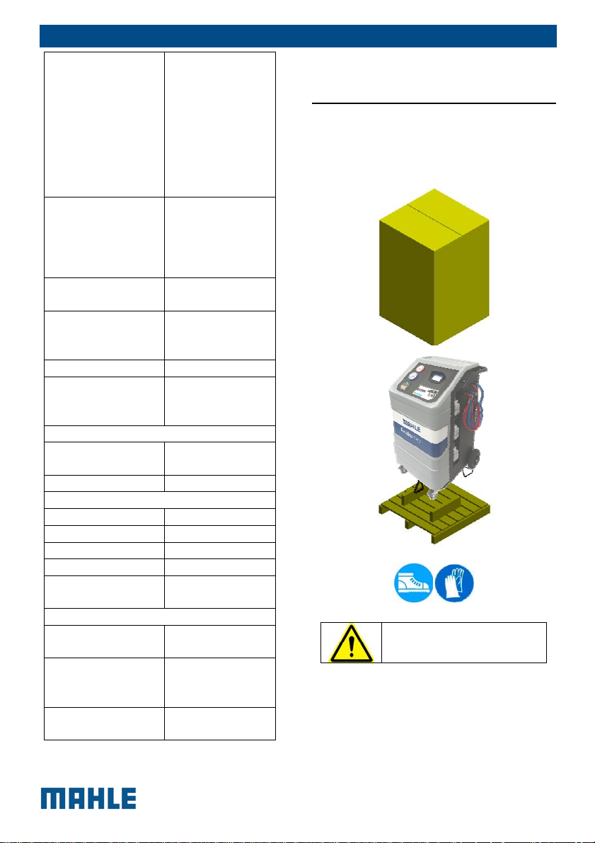
7.1.1 Unpacking ACX150/250
The manufacturer disclaims all
responsibility for damage to objects
and/or persons resulting from the
equipment being wrongly removed from
the pallet, or from the operation being
made by unsuitable personnel, with
RISK OF OVERTURNING
© MAHLE
improper means/protections and
without complying with the existing
laws on manual handling of loads and
with the operations described in this
manual.
Cut the strap and remove the carton.
Cut the straps securing the unit to the
pallet.
Remove the equipment from the
pallet (2 operators required)
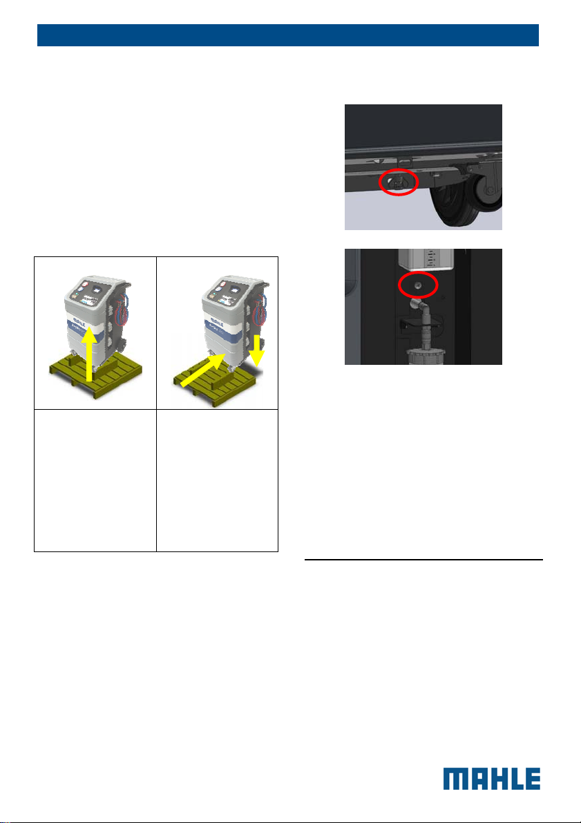
EN | 16 | ACX150/250 | Commissioning
REFRIGERANT SCALE SCREW
RELEASE
Lift both front
wheels by
levering with the
handle and on
rear wheels (this
way the operators
must not lift the
full weight of the
unit)
Keep the pallet, carton and scratch
protection film for use when returning the
unit. The unit rolls on wheels; the two
smaller wheels can be locked.
ACX150/250 is supplied with the
accumulation tank empty. This prevents
problems in shipping the unit.
Slowly lower
the unit from the
pallet by means
of the rear wheels
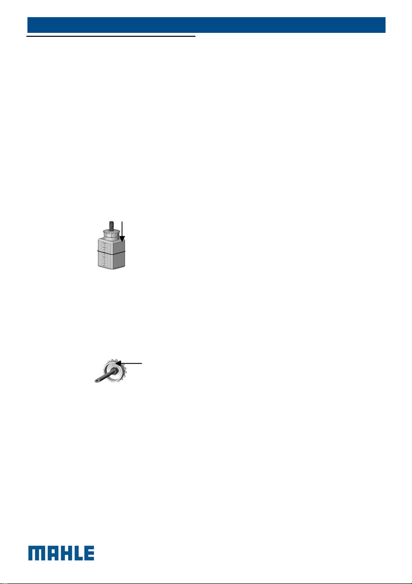
The tool is transported, with the scale
blocked by a locking screw to avoid the
load cell damage. The scales locking
screw is placed on the equipment
bottom/right side (see the box shown
above) and is formed by a bolt. For
commissioning, unscrew the screws.
8 Commissioning
8.1 Connections
The unit has to be positioned on a
horizontal surface to ensure the correct
operation.
The unit has to be connected to the
electric mains following instructions on
the identification plate of the unit applied
next to the main switch, mainly as to
applicable voltage and power.
© MAHLE
EN | 17 | ACX150/250 | Commissioning
8.1.1 Positioning and connection
HANDLING: During handling, the
minimum devices required for
correct handling shall be ensured,
as provided for by accident
prevention provisions.
POSITIONING: Place the unit in a
stable place. The location must be
well ventilated, with a good rate of
change of air. The unit must be
located at least 10 cm from any
potential obstacles to its internal
ventilation. Keep the unit away
from rain and excessive humidity
as they can irreparably damage it.
In addition, the equipment must
never be directly exposed to the
sunrays or to excessive dust.
INSTALLATION: the unit must be
installed by a specialised
technician in scrupulous
observance of in accordance with
electrical engineering principles.
The use of the equipment in
explosive atmosphere is
forbidden.
CONNECTIONS: since the unit is
connected to the main power
supply, it must be properly
grounded with its power plug
GND pin. Failure to ground the
unit can damage it and
constitutes a risk of fatal injury to
the operator. Position the unit so
that the power plug is easy for the
operator to access.
Power mains
connection
Vehicle A/C system
connections
ATTENTION: Leave the quick
coupling taps closed when the
unit is not in use and at the end of
vehicle service operations.
8.2 Initial verification
Execute the following actions in sequence
by following the display guided procedure
and the illustrations on the screen of the
equipment:
Refrigerant weight check
Oil weight check
First tank filling
It is possible to interrupt the initial check
and print a report with the equipment
printer in which the checking status is
reported. The equipment cannot operate
in automatic mode until all the steps of
the initial check have been completed.
CAREFULLY ABIDE BY
THE FOLLOWING
INSTRUCTIONS TO
AVOID DANGER TO
PERSONS, THE
DISCHARGE OF
REFRIGERANT IN THE
ATMOSPHERE
© MAHLE
Let us consider as first filling the one
carried out during the initial check with
internal tank of the equipment free of
refrigerant and containing air.
Set the quantity of refrigerant to fill (at
least 3 kg) and follow the guided
procedure shown on the display.
Check that the equipment hoses are not
connected and positioned in the hose
winder. Start the procedure that initially
implies the creation of vacuum in the
internal tank. This phase will take 15
minutes and will act on the whole
equipment.
Only when the message appears asking
to connect the charge tank, connect the
HP quick coupler (colour red) of the unit
to an external refrigerant tank using the
supplied adaptor.
When the message occurs open the
coupler by turning the knob clockwise.
Open the valve on the external tank.
Just right before reaching the planned
quantity of refrigerant, the unit will stop
and ask the user to close the external
refrigerant tank. Then, the device will
continue the recovery from the hoses and
ends when these are empty. Hence, it is
necessary to open the HP quick-coupler
and disconnect it from the external tank.
Thanks to the E³ CONNECT function, the
refrigerant - usually kept between the
cylinder fitting and the hose quick-coupler
until the end of the process - will not be
released in the environment.
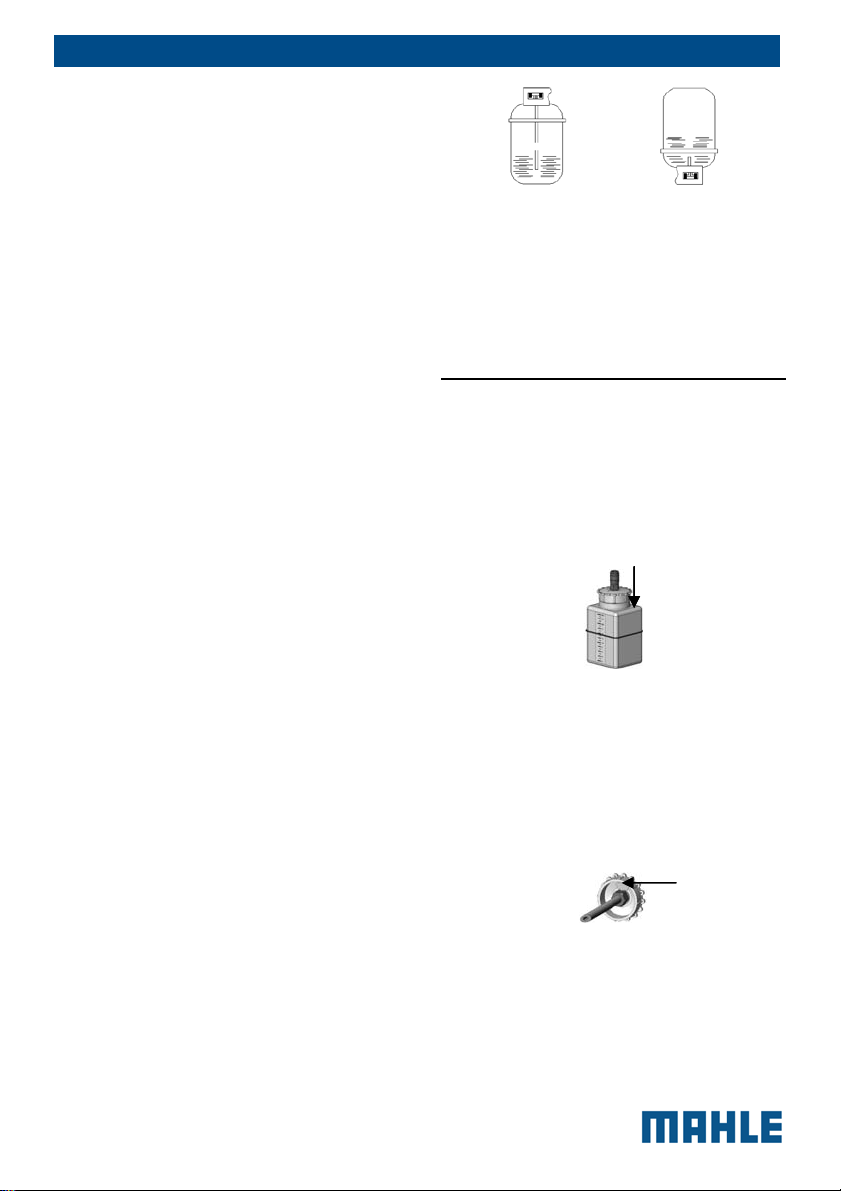
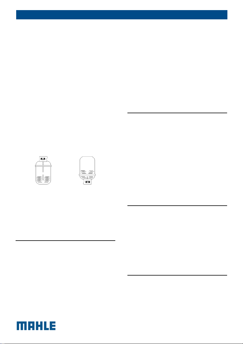
There may be two types of source tanks:
with plunger and without plunger.
Tanks with plunger shall remain upright
to be able to transfer liquid refrigerant; for
this type of tanks connect to the L (liquid)
coupler.
Tanks without plunger have only one
valve, so they must be turned upside
down to transfer the liquid refrigerant.
EN | 18 | ACX150/250 | Commissioning
The LP gauge indicates the pressure
inside the external tank.
After some minutes the unit will
automatically end the function.
At the end the weight of the charged
refrigerant will be displayed.
8.3 New oil bottle filling
To fill the new oil bottle (Fig.1 Pos. 7) it
has to be extracted from its housing by
means of the quick coupler on the top of
the bottle; slightly press downward the
coupler ring nut to extract it.
Fill the bottle by paying special attention
to the “oil care” valve.
This valve is made of a silicon polymer
membrane; it compensates pressure
variations within the bottle and stops
humid air infeed inside thus preserving
the new oil inside.
After filling, close the bottle and place it
back in its seat.
© MAHLE
EN | 19 | ACX150/250 | Setup
8.4 UV dye bottle filling
The UV Dye is a substance made up of a
yellow-green coloured fluorescent
pigment, which means that, when lit by
an ultraviolet lamp, it becomes
fluorescent and thus visible.
The UV dye can therefore be used to
detect leaks of a small entity inside the
auto vehicle A/C system.
To fill the UV dye bottle (Fig.1 Pos. 6) it
has to be extracted from its housing by
means of the quick coupler on the top of
the bottle; slightly press downward the
coupler ring nut to extract it.
Fill the bottle by paying special attention
to the “oil care” valve.
This valve is made of a silicon polymer
membrane; it compensates pressure
variations within the bottle and stops
humid air infeed inside thus preserving
the new oil inside.
After filling, close the bottle and place it
back in its seat.
9 Setup
From the SETUP menu it is possible to
select parameters and activations before
starting cycle:
ELECTRIC COMPRESSOR FUNCTION
by selecting this entry, one may
change the type of Oil to inject into
the A/C system.
E³ CONNECT
by selecting this entry, you can
enable the E³ CONNECT function
(the E³ CONNECT quick coupler
must be present on the car).
CHARGE MODE
by selecting this entry, one may
decide whether to enable use of the
Quick Mode or Zero Tolerance
charge method
AC PERFORMANCE TEST
by selecting this entry, one can
enable or disable the AC
PERFORMANCE TEST.
REFRIGERANT CLEAN
by selecting this entry, one may
decide whether or not to enable the
refrigerant clean function, which
enables an additional recycling,
within the station itself, started in
automatic when it is switched on but
not in use. This function ensures a
higher level of purity of the recycled
refrigerant to the advantage of the
service quality.
RECOVERED GAS AND OIL PRINTING
selecting this entry, you can choose
whether you want to enable
displaying and printing of the
recovered gas quantity. Setting
available only with printer installed.
REPORTS SAVING MODE
by selecting this entry, you can save
the reports of the performed charges
(automatic cycle or Reg. 842/2006).
© MAHLE
REPORT DATA
select what data you would like to
include in the saved and printed
report: -license plate, -km, -client’s
name, -technician’s name
HOSES LENGTH
by selecting this entry, it will be
possible to change the length of the
charge hoses.
UNIT OF MEASURE
selecting this entry, you can modify
the pressure unit of measurement
(switching from Bar to PSI)
CLOCK ADJUSTMENT
by selecting this entry, date and time
of the station may be changed.
GARAGE DATA
by selecting this entry, one can enter
the garage data to be printed on the
end of cycle report.
LANGUAGE
by selecting this entry, any language
present in the database may be set.
In case you choose a language with
unintelligible characters. Switch off
the equipment , keep pressed the
touch screen and switch on the
equipment in the meanwhile, you will
be directed to the language setting
menu.
RIGHT / LEFT-HAND DRIVE
It allows setting the database for
operations on A/C systems of
vehicles with right-hand or left-hand
drive and return the exact value of
gas and oil to be injected.
EN | 20 | ACX150/250 | A/C system charge
STARTUP SCREEN
By selecting this entry, you can
decide whether the startup screen of
the unit will be the databank page or
the main menu page.
DATABASE ACTIVATION
by selecting this entry, you will
receive the “database activation
request code” to be provided to your
distributor in order to be able to buy
the database activation/update and
subsequently receive the “ACX
activation key”.
GAS TYPE:
by selecting this entry, you can learn
the type of gas the unit is set for, to
change the type of gas contact an
Authorised MAHLE Service Centre.
DEFAULT SETUP
By selecting this entry, you can
restore the unit default settings.
MAHLE reserves the right to add
new parameters to make the
equipment increasingly versatile
and adaptable to market’s needs.
10 A/C system charge
10.1 Preliminary operations
The recovery and charge operations have
be carried out after the car /AC system
has run for some time; however, an
excessively hot A/C system has to be
avoided since the next charge phase
could be adversely affected by high
pressures.
The vehicle must not be prepared in a
special way; connecting hoses have to be
© MAHLE
EN | 21 | ACX150/250 | A/C system charge
attached by identifying their position.
Vehicle details necessary for the
performance of the charge/recovery/
vacuum cycle are the amount of
refrigerant and the type and quantity of oil.
These data are often found on the engine
compartment plate or on the technical
manuals.
As to oil quantity technical manuals of
cars, systems as well as available details
in general indicate the total quantity of oil
in the system.
Indeed the amount of oil to be charged is
that extracted during the refrigerant
recovery phase which is very small. In the
car A/C system you have to add only the
oil amount necessary to restore the
amount set by the car manufacturer
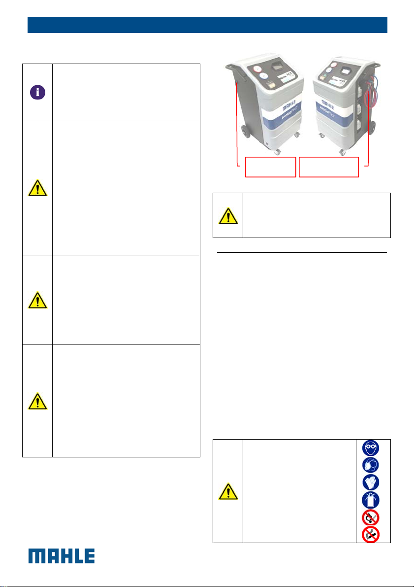
FEATURES
Your new A/C service station is equipped
with new E³ CONNECT quick couplers.
These new couplers offer the following
functions:
1. Avoid dispersion of the refrigerant,
allowing the recovery by the tool
(thus protecting the environment and
saving refrigerant).
2. Automatic leak test of the car A/C
system valve at the end of the
service.
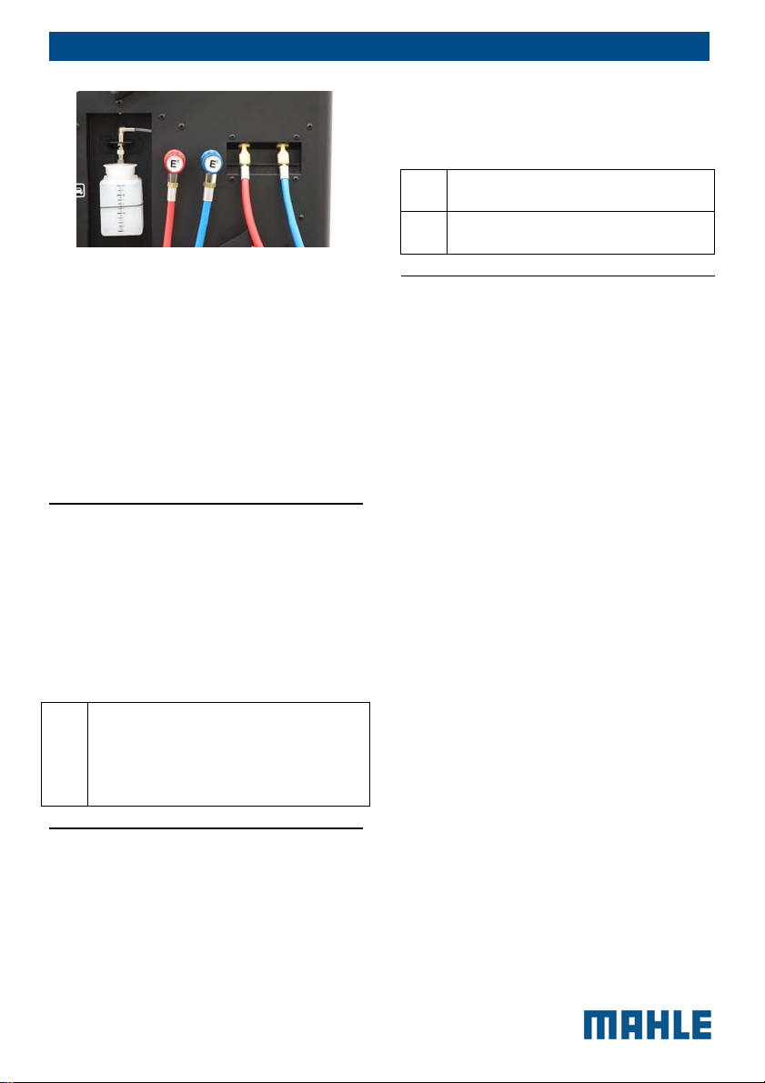
After connecting the quick couplers to the
(high pressure) HP and (high pressure) LP
connectors of the vehicle, screw the
valves only when required by the
messages on the tool display.
10.2 Non-condensable gas
discharge
The station is equipped with the AIR
PURGE SYSTEM function, which allows
automatically detecting and purging noncondensable gas (mainly air) accumulated
within the tank.
If the station detects non-condensable
gas in the tank, it will automatically run
the non-condensable gas discharge
procedure.
Running this procedure is very important
to ensure the ideal working parameters
for the station operation. The presence of
non-condensable gas in the tank will
increase the pressure inside the tank and,
therefore, will slow down and reduce the
efficiency of charge cycle on the vehicle.
The procedure will take a few minutes,
and its duration may vary according to
the amount of non-condensable gas
within the tank.
NON-CONDENSABLE
GAS VENT VALVE
WARNING: Leave the quick
coupling taps closed when the
unit is not in use and at the end of
vehicle service operations.
WARNING: For the Air Purge
System procedure to be executed
manually, the station must have
been off for at least one hour.
© MAHLE

10.3 Quick mode and zero
tolerance charge mode
ACX150/250 can apply two different
refrigerant charge modes; the first one is
called Quick mode and features the
opening of the charge valve by charging
refrigerant through the HP port. By the
Quick Mode part of the refrigerant
remains into the hoses and is
compensated by software calculation.
Whenever the charge is not completed
the UNIT shifts automatically to the Zero
Tolerance mode.
The Zero Tolerance function is the
second charge procedure, an alternative
to the Quick Mode.
It features a more accurate charge and
guarantees a successful charge (it
however requires a longer time and the
operator's intervention).
If the car A/C system is equipped with
both couplers or with LP coupler only,
there are two slightly different working
modes; in any case if only the HP coupler
is available the Zero Tolerance mode is
not applicable.
With both HP and LP couplers available
the Zero Tolerance features the charge of
the selected refrigerant amount into the
system through the HP hose; then
refrigerant remained into the HP hose is
sucked by the car system – engine and
compressor running – through LP (after
disconnecting and closing the HP
coupler).
In case the LP coupler only is available
the station charges the system with 50%
of the selected amount with car
compressor off and waits for 10 minutes
before recalling the operator. This wait
time – quite rare since most of cars are
equipped with HP coupler too – allows
the refrigerant charged near the
EN | 22 | ACX150/250 | Automatic cycle
compressor – that is LP side – to
evaporate to prevent any damage to the
compressor during the admission of liquid
phase refrigerant. Then, after car and A/C
system switch ON charge continues
through timed charge of refrigerant
through hose LP, such charges start
exclusively if the LP pressure is lower
than 3 bar (this threshold is adjustable).
11 Automatic cycle
The access to Automatic cycle can be
achieved selecting Database, Last Cycle
or My database (a 100 personal
automatic cycle) .
11.1 Automatic cycle data
loading
11.1.1 Database
MAHLE offers customers purchasing
ACX150/250 the possibility of enhancing
potentials of the UNIT through the
database.
This database contains all data related to
the A/C system of most vehicles. Hence,
it will be possible to speed up the charge
operations of the system with the aid of
the data provided by the database.
Make
Model
Version / engine capacity
Year
System
11.1.2 Last cycle
It loads the parameters of the last
automatic cycle.
© MAHLE

EN | 23 | ACX150/250 | Automatic cycle
11.1.3 My database
It allows loading the parameters of the
automatic cycle previously saved by the
user.
11.1.4 Direct input
It loads the default parameters of
automatic cycle.
11.2 Automatic cycle data
setting
After selecting the type of A/C system the
main page is shown with the following
preset values
Vacuum phase (recommended
values but changeable – they do
not depend by the car selected)
Vacuum duration
Leak test duration
Oil Charge mode and quantity of
oil that will be charged into the
system
o OIL: <value> g. It
charges the quantity of
oil that has been set.
o REC. + <value> g. It
charges the quantity of
recovered oil plus the
quantity of oil that has
been set
o NO OIL. No oil is
charged during the
charge cycle
Oil type: It sets the oil type being
used. PAG (ISO46/100/150) or
POE, it does depends by the
selected vehicle.
It is possible to select the charge
of the UV dye (a single shot of about
8 g.)
amount of refrigerant that will be
charged into the system and the
amount of refrigerant available in
the inner tank of the UNIT.
Charge type: It allows selecting
from which hose the service is
carried out, according to the
type of system.
o Charge from HP hose
(red)
o Charge from LP hose
(blue)
o Charge from HP hose
(red) and LP hose (blue)
o Charge from HP hose
(red) on the system low
pressure side. Specific
for some Renault
models.
At the end of the setup, press the
“START” button to start the automatic
cycle.
Or press Save if you want to save this
cycle with a name in a My Database
record.
11.2.1 Electric Compressor
Function
Before connecting the ACX150/250 hoses
to the A/C system of the vehicle, select
the Vehicle Compressor Type.
If the selected type is Electric (high
voltage), a special function named
“Electric Compressor Function” will be
executed to clean the hoses from any
previous oil residue.
When the following message appears:
Connect LP and HP quick coupler to their
support connectors on ACX150/250.
© MAHLE
After the connection, press “YES” to
proceed and follow the instructions
showed on the screen.
12 Manual cycle
The access to manual cycle can be
achieved selecting the functions in the
Manual Cycle menu.
12.1 Recovery
In the MANUAL CYCLE menu select
RECOVERY function.
Press and start the recovery function and
follow the tool instructions. If there is no
pressure inside the system, this function
cannot be started.
POSSIBLE ERROR INDICATION
Too high pressure in the A/C
service unit.
Valves or couplers closed or
system empty.
12.2 Vacuum
From the main menu select MANUAL
CYCLE and press VACUUM.
Connect the HP – LP couplers or the
single coupler to the vehicle system and
screw the couplers. Now set the time for
the vacuum and control phase, if different
EN | 24 | ACX150/250 | Manual cycle
from the default settings. The vacuum
phase is automatically followed by the
“vacuum test” phase.
Press START to start the vacuum phase.
POSSIBLE ERROR INDICATION
System pressurised
POSSIBLE ERROR INDICATION
System not tight
12.3 Charge
In the main menu select MANUAL CYCLE
and then CHARGE.
Set the following items :
Charge mode and quantity of oil
that will be charged into the
system
o OIL <value> g. It
charges the quantity of
oil that has been set.
o REC. + <value> g. It
charges the quantity of
recovered oil plus the
quantity of oil that has
been set
o NO OIL. No oil is
charged during the
charge cycle
Oil type: It sets the oil type being
used. PAG (ISO46/100/150) or
POE
UV: Option for the charge of UV
dye
Amount of refrigerant that will be
charged into the system and the
amount of refrigerant contained
in the inner tank of the UNIT.
Charge type: It allows selecting
from which hose the service is
carried out, according to the
type of system.
© MAHLE

EN | 25 | ACX150/250 | Special test
Connect the couplers to the vehicle
fittings and follow the instructions on the
screen page.
Press START to begin the refrigerant
filling phase.
o Charge from HP hose
(red)
o Charge from LP hose
(blue)
o Charge from HP hose
(red) and LP hose (blue)
o Charge from HP hose
(red) on the system low
pressure side. Specific
for some Renault
models.
POSSIBLE ERROR INDICATION:
The amount of refrigerant in the
A/C service units tank is less than
that required. Closed hoses, charge
impossible.
THIS PHASE HAS TO BE
CARRIED OUT EXCLUSIVELY
ON A/C SYSTEM UNDER
VACUUM (AFTER A VACUUM
PHASE HAS BEEN PULLED).
12.4 Flushing (with optional
accessories)
After performing a lot of charge cycle or
after replacing components or parts of
the /AC circuit on a vehicle it is advisable
to carry out a system flushing.
The system washing (Flushing) consists in
purifying the vehicle cooling system
through several R1234yf/R134a
refrigerant flushes, by recovering it each
time, so that the impurities can be filtered
little by little through the additional filter.
Thanks to its specific design,
ACX150/250 automatically manage the
flushing process so that the process
becomes fully automatic.
Once the (optional) flushing kit has been
installed, as described in the instructions
included in the kit, and after selecting the
specific function for the kit being used,
start the phase.
In case of problems or errors during this
phase, a message will be displayed,
identifying the type of error.
It is possible to interrupt the phase in
progress at any time.
12.5 Hoses drain
To empty the charge hoses completely
perform the HOSES DRAIN phase.
Select in the menu the HOSES DRAIN
function. Wait the end of the procedure.
13 Special test
13.1 AC performance test
To check the vehicle A/C system status –
for instance in case there is no flow of
cold air from flaps – pressure values can
be checked.
Connect the HP - LP couplers or the
single coupler to the vehicle system.
Under the sequence guided by the
software perform the following preliminary
operations on the vehicle:
1. Turn on the A/C system
2. Set temperature at
minimum level.
3. Set fan speed at maximum
level; close all the flaps
except the central one and
© MAHLE
In the MANUAL CYCLES menu, select
the AC PERFORMANCE TEST function.
Execute the AC PERFORMANCE TEST
following the instruction.
And at the end make sure that both
values on LP and HP gauges fall within
the values shown on the display.
It is possible to interrupt the phase in
progress at any time.
set air distribution to
central position.
4. Keep engine at accelerated
idle at constant speed for
at least 2 minutes.
5. Check the pressure values
within about 3 - 5 minutes.
PRESSURE VALUES CHANGE
CONSIDERABLY WHEN
AMBIENT TEMPERATURE
CHANGES. KEEP THIS IN MIND
WHEN CHECKING PRESSURE
VALUES
13.2 Refrigerant clean
By selecting this function, you can start
the refrigerant clean function, allowing for
a further recycle, which is internal to the
station itself. This mode guarantees a
higher level of the service quality.
14 Maintenance
ACX150/250 is a remarkably reliable unit,
manufactured using the highest quality
components, making use of the most
advanced production techniques.
Please contact an authorized technical
service centre for purchasing original
spare parts.
EN | 26 | ACX150/250 | Maintenance
The access to manual cycle can be
achieved selecting the functions in the
Maintenance menu.
INTERVENTIONS ON SERVICE
STATION COMPONENTS
WHICH ARE NOT MENTIONED
MAKE SURE THE TOOL IS
UNPLUGGED FROM THE
POWER MAINS BEFORE
IN THE FOLLOWING
PARAGRAPHS ARE
PROHIBITED.
OPENING.
14.1 Report exporting
In the main menu select MAINTENANCE
and press “REPORT EXPORTING”.
By selecting this function, is possible to
export the report on USB Key and
manage it on PC with ACX Manager.
14.2 Internal cylinder fill
In the main menu select MAINTENANCE
and press “INTERNAL CYLINDER FILL”.
Set the quantity of refrigerant to fill and
follow the guided procedure shown on
the display.
The set value is limited to avoid to fill too
much the internal cylinder.
Only when the message appears asking
to connect the charge tank, connect the
HP quick coupler (colour red) of the unit
to an external refrigerant tank using the
supplied adaptor.
When the message occurs open the
coupler by turning the knob clockwise.
Open the valve on the external tank.
Just right before reaching the planned
quantity of refrigerant, the unit will stop
and ask the user to close the external
© MAHLE
EN | 27 | ACX150/250 | Maintenance
refrigerant tank. Then, the device will
continue the recovery from the hoses and
ends when these are empty. Hence, it is
necessary to open the HP quick-coupler
and disconnect it from the external tank.
Thanks to the E³ CONNECT function, the
refrigerant - usually kept between the
cylinder fitting and the hose quick-coupler
until the end of the process - will not be
released in the environment.
There may be two types of source tanks:
with plunger and without plunger.
Tanks with plunger shall remain upright
to be able to transfer liquid refrigerant; for
this type of tanks connect to the L (liquid)
coupler.
Tanks without plunger have only one
valve, so they must be turned upside
down to transfer the liquid refrigerant.
The LP gauge indicates the pressure
inside the external tank.
After some minutes the unit will
automatically end the function.
At the end the weight of the charged
refrigerant will be displayed.
14.3 Self leak test
In the main menu select MAINTENANCE
and press “SELF LEAK TEST”.
A leak test is carried out on the internal
components of ACX150/250.
This phase includes:
Hoses emptying
Vacuum test
This test allows to check the tightness of
the internal circuits of the equipment from
the solenoid valve, allowing the fluid
outflow from the internal cylinder, to the
manifold, (metallic component housing
the check solenoid valves) to the
compressor infeed, including the dryer
filter leak test.
In case of failed leak test, it is necessary
to check the charge hoses conditions
and the quick couplers leak, and make
the possible repair and then repeat the
test.
14.4 Cylinder refrigerant
view
In the main menu select MAINTENANCE
and press “CYLINDER REFRIGERANT
VIEW”.
The available refrigerant for next
recharging is 2 kg less than the total
contents of the cylinder.
Two kg is the minimum quantity that
should be always left in an operating
ACX150/250.
14.5 Air purge
In the main menu select MAINTENANCE
and press “AIR PURGE”.
By selecting this function, is possible to
check the non condensable gases
condition (high level red area, low level
green area ) and if necessary start
manually the discharge.
14.6 Pressures zero
In the main menu select MAINTENANCE
and press “PRESSURES ZERO”.
This function allows to determine and
store the atmospheric pressure value.
© MAHLE

We recommend running this procedure
every time the ACX150/250 will be moved
from a location to another with a different
altitude.
14.7 Counters
In the main menu select MAINTENANCE
and press “COUNTERS”.
In the COUNTERS page, at any time, the
vacuum pump and compressor hours of
life can be displayed; besides, remaining
time before replacement of vacuum pump
oil and dryer filter can also be displayed.
This is useful to understand if some
maintenance activity should be performed.
14.8 E³ pump - pump oil
change
The ACX150/250 is equipped with a
special function named E³ PUMP that
enables to optimize the vacuum pump oil
use by avoiding the replacement every 60
hours of operation.
E³ PUMP is a special function allowing to
extend even to 1000 hours the life of the
pump oil used in the station. E³ PUMP
function performance is suggested at the
end of 60-hour operation intervals of the
vacuum pump and can be manually
activated in the MAINTENANCE menu
pressing E³ PUMP.
E³ PUMP procedure has to be started
only after checking and, if necessary,
topping up the pump oil level and lasts 1
hour: during this time the tool cannot be
used.
During the procedure the oil is
automatically purified from the gaseous
polluting residues absorbed during the
emptying operations of vehicles air
conditioning systems.
EN | 28 | ACX150/250 | Maintenance
At the end of the procedure, the vacuum
pump performance check is carried out
and a result to the operator is signalled.
In case of negative result you have to
replace the vacuum pump oil.
After 1000 hours of vacuum pump
operation since the last oil change, the E³
PUMP procedure cannot be activated
anymore and you have to replace the oil
according to the following instructions.
Required tools:
1 Hex screwdriver (2.5 mm)
1 Medium-sized flathead
screwdriver
1 Hex key (10 mm)
For replacement, comply with the
instructions outlined below:
1. Disconnect the unit from the
mains.
2. Remove the six screws that fix
the front door of the unit and
remove it.
3. Place a bowl underneath the
machine, right under the pump
oil drain hole. Open the upper
plug and then the lower plug to
drain the used oil contained
within the vacuum pump.
© MAHLE
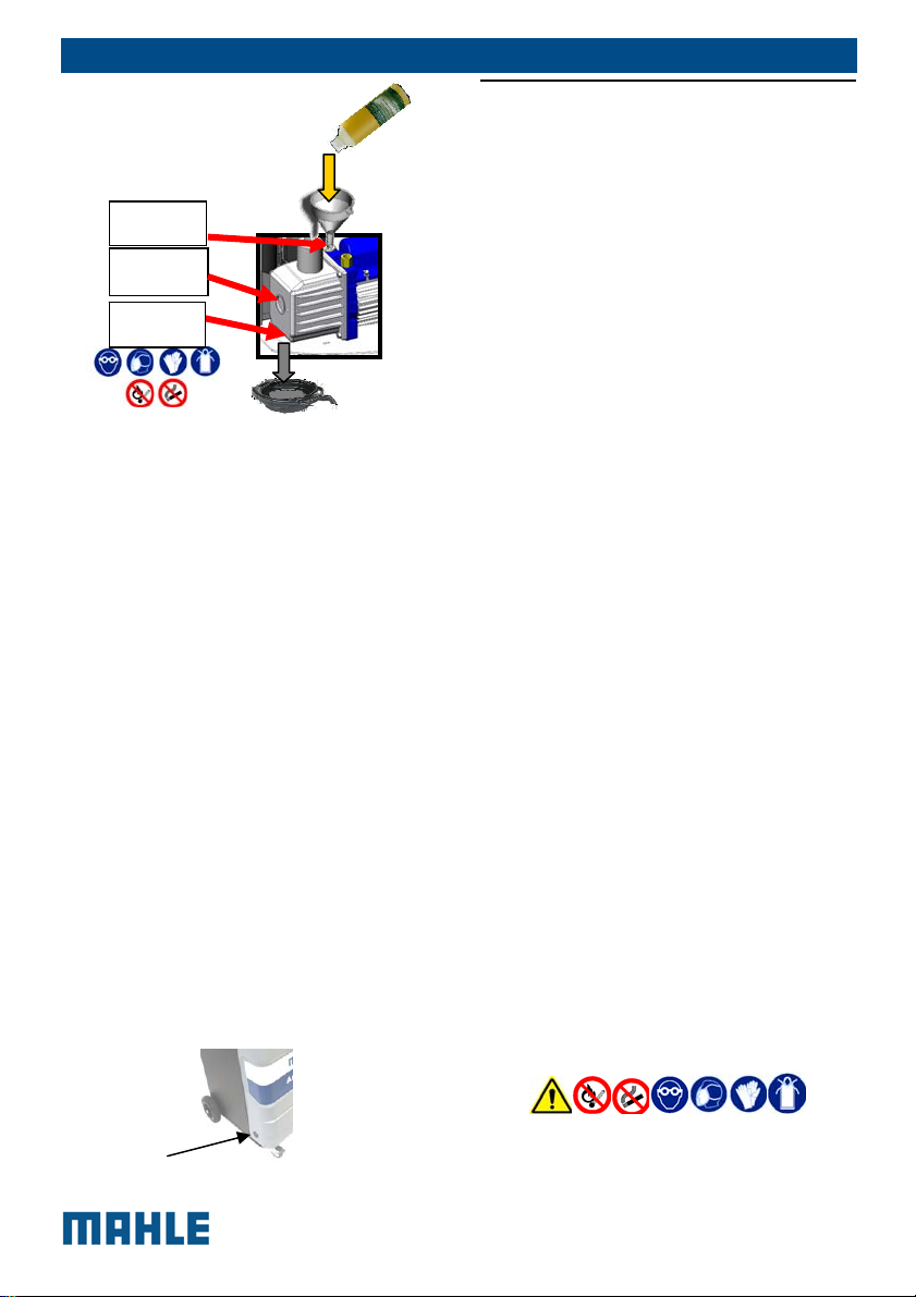
EN | 29 | ACX150/250 | Maintenance
Upper filling plug
Oil inspection
window
Lower
drain plug
4. Once the pump has been
emptied, screw the lower plug
again.
5. Fill the pump with new oil
through the upper opening,
using a funnel if needed. Bring
new oil level halfway through
the oil inspection window.
6. Once the pump has been filled,
close the upper plug.
7. Once oil has been replaced,
switch on the unit and from the
MAINTENANCE menu select
PUMP OIL REPLACEMENT:
press the “RESET” key to set
the counter.
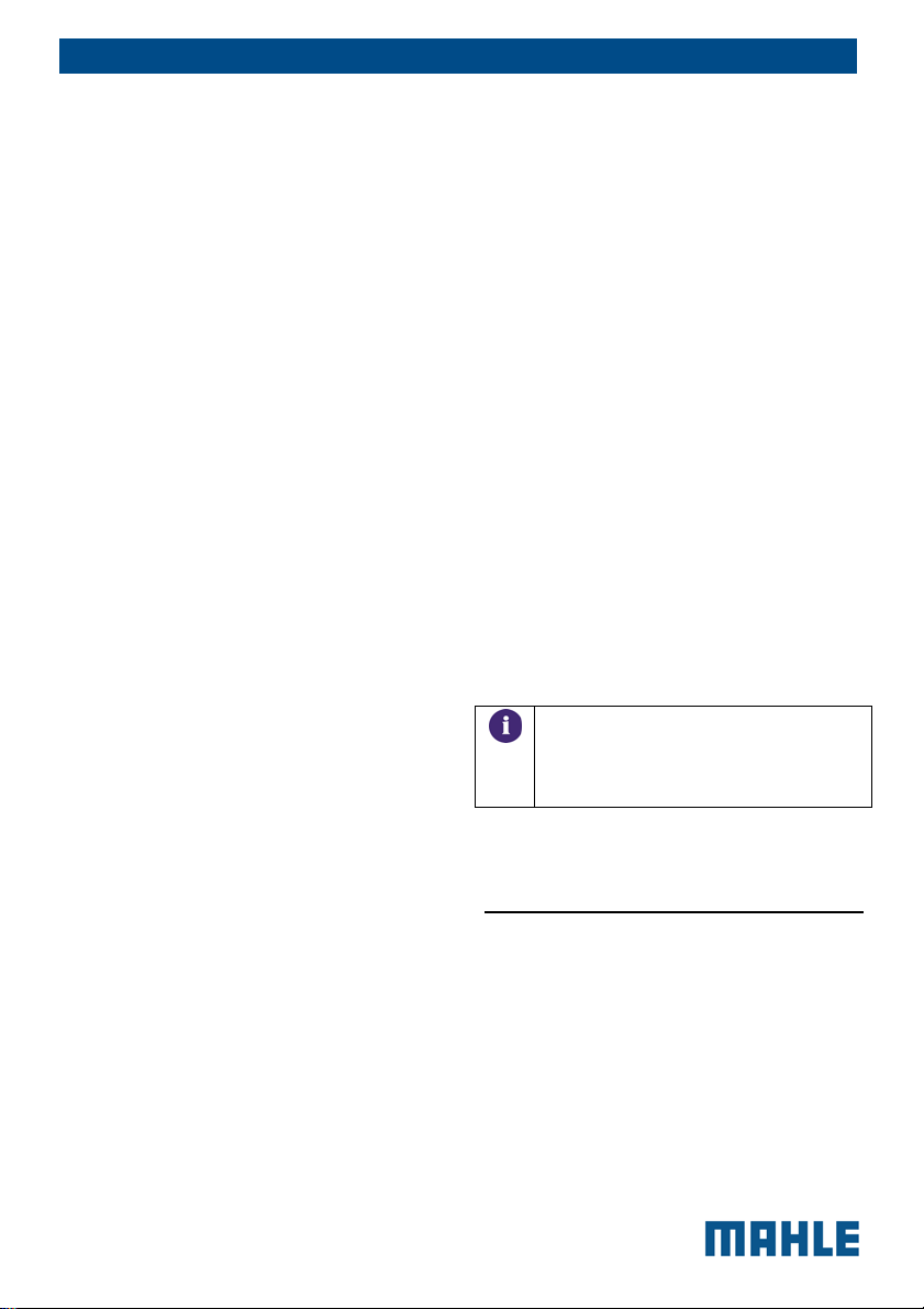
14.8.1 Oil pump visual check
Without opening the equipment is always
possible to remove the rubber tap in the
following position to check level and the
clearness of the oil inside the pump.
14.9 Dryer filter
replacement
The dehydrator filter must be replaced
after having dehydrated 150 kg of
refrigerant fluid, since the filter capacity to
keep the humidity present in the
refrigerant will run out.
To replace the dryer filter, from the
MAINTENANCE menu select DRYER
FILTER REPLACEMENT: press “START”
to set the counter to zero and to start the
filter replacement procedure. Insert the
code of the new filter. Now you can
replace the filter.
Required tools:
1 Hex screwdriver (2.5 mm)
1 regular or torque Hex key (24
mm)
1 Hex key (17 mm)
For replacement, comply with the
instructions outlined below:
1. disconnect the HP and LP
hoses from other
systems/circuits or vehicles
and close the quick
couplers
2. wait the ends the hoses
emptying.
3. confirm to have already
worn the personal protective
equipment (PPE) and follow
the safety regulations in
force.
© MAHLE
DANGER OF CONTACT WITH R134a
REFRIGERANT and motor vehicle A/C
system oil
4. Before opening the doors of
the equipment, switch off
the equipment and
disconnect the power
supply cord.
DANGEROUS VOLTAGE HAZARD
5. Remove the six screws that
fix the front door of the unit.
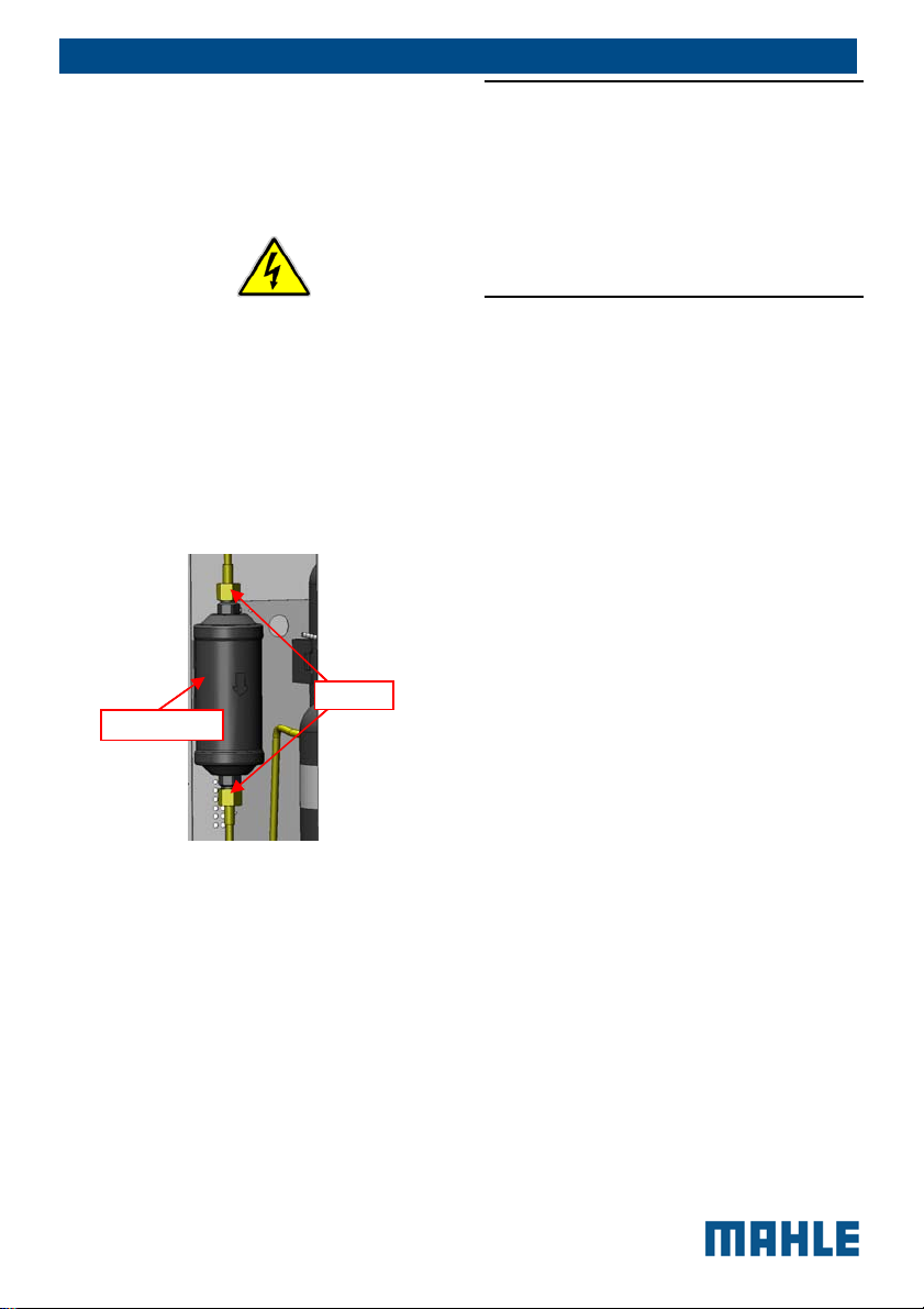
6. Unscrew the 2 connection
nuts of the filter by means of
the hex keys.
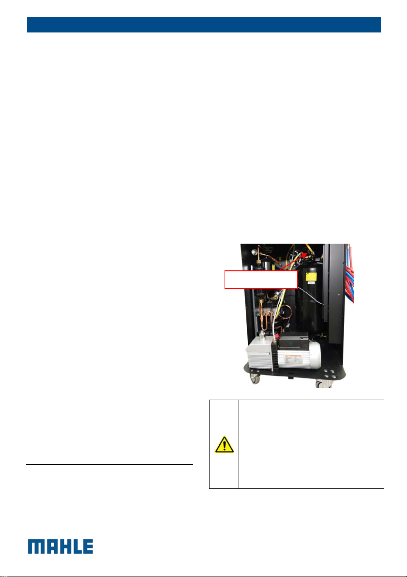
7. Remove the straps that
wind up the filter
DRYER FILTER
8. Install the new filter paying
attention to the position of
gaskets and to the direction
of the arrow indicating the
fluid flowing direction.
9. Screw the two connection
nuts of the filter.
10. Replace the front panel
11. Carry out the automatic leak
test requested by the
software when switched on
again after the filter
replacement.
NUTS
EN | 30 | ACX150/250 | Maintenance
14.10 System info
In the main menu select MAINTENANCE
and press “INFO”.
In the INFO page, at any time, the
software version and the serial number
can be displayed.
14.11 System update
The firmware (software) can be
updated by way of a USB stick.(where
the new version is stored).
1. Insert the USB stick in
USB port (fig.3 pos.4)
Power on ACX150/250.
2.
In the main menu select
3.
MAINTENANCE and
press “SYSTEM
UPDATE”.
A message will appear
4.
that the unit is loading
an update.
5.
The unit may load an
updated language file,
database file and
configuration file while
updating.
Once unit is updated,
6.
the software version
string on the
introduction screen
during power up will
change.
© MAHLE

EN | 31 | ACX150/250 | Maintenance
14.12
Maintenance of
printer
To change the roll of paper follow
instructions below:
1. Open the lid of the printer as
shown
.
2. Position the roll of paper inside
the housing in the rotation
direction indicated in the picture;
3. Pull the paper out of the housing
as indicated in the picture and
close the lid ;
14.13 Periodic checks
A/C service stations (pressure equipment
set) must be checked over regularly as
provided by local legislation.
According the local legislation contact the
technical customer service or the
competent body for at least the following
checks.
Make sure no corrosion or
leakage are present in the tank
and in the other cylinder and
metallic part of the equipment;
under normal conditions of use,
the tank life is at least 20 years
(in the absence of wear and
other types of damages).
If the automatic safety valve trips,
contact technical service to have
the unit checked over, resolve
any problems and replace the
valve if necessary.
© MAHLE
4. The printer is ready for printing.
Check presence of the device
with references indicated above,
wholeness of connection cables
and connector, and the correct
connection to the equipment
printed circuit board. In case the
pressure switch must intervene,
please contact the technical
customer service that will check
the equipment and remove any
defect.

Periodically check that the
external charging hoses, red
(HP) and blue (LP), are in good
order and undamaged. In case
damages to the hoses are
detected, stop using
ACX150/250 and contact the
technical customer service for
the related replacement.
Verify that the lubricants (pump
oil) and filters (dryer) have been
replaced according to the
scheduled periodicities for a
proper functioning of the
equipment.
14.14 Refrigerant type
replacement
Your ACX150 station is supplied with the
standard fittings to operate with
refrigerant R134a, but it can be easily
adapted to be used with refrigerant gas
R1234yf.
Contact an authorized Service Centre to
ask for the adaptation kit.
The adaptation must be performed by a
technician of an Authorised Mahle Service
Centre, who will install the specific
components for use of R1234yf. He will
also carry out all configurations and
verifications required by the refrigerant
type replacement procedure.
15 Disposal
15.1 A/c service unit
disposal
At the end of its service life, this
equipment must be disposed of as
follows:
EN | 32 | ACX150/250 | Disposal
Contact the service center to
have the refrigerant in the unit
recovered and recycled.
Consign the unit to an
authorized collection center
according to local legislation.
15.2 Recycled materials
disposal
Consign the refrigerant recovered from
the unit to the refrigerant supplier for
proper disposal or recycling. Lubricants
extracted from vehicles’ A/C systems
must be consigned to an used oil
collection center.
15.3 Packaging disposal
Electronic and electrical A/C service
equipment must never be disposed of
with domestic waste, but recycled
appropriately.
The packaging must be disposed of in
conformity with local legislation.
This contributes to protecting the
environment.
16 Spare parts
Spare parts available to the user:
4.5 m red charging hose
© MAHLE

EN | 33 | ACX150/250 | Spare parts
4.5 m blue charging hose
Blue LP quick coupler and red
HP quick coupler
USING NON
ORIGINAL/UNAPPROVED
SPARE PARTS OR
ACCESSORIES CAN
COMPROMISE THE SAFETY OF
ACX150/250.
Dryer filter
Vacuum pump oil
Consumables available to the user:
Vehicle A/C system oil
UV dye
Thermal paper rolls
Further spare parts are available through
the Service Centers authorised by
MAHLE or by its reseller.
© MAHLE

Date Result of
(pass/fail)
MAINTENANCE FORM
Refrigerant receiver load cell check
Maintenance technician
check
identification
EN | 34 | ACX150/250 | Spare parts
Maintenance technician
signature and stamp
© MAHLE

EN | 35 | ACX150/250 | Spare parts
MAINTENANCE FORM
Other checks/maintenance/repairs
Job Date Result of
check
(pass/fail)
Maintenance
technician
identification
Maintenance
technician
signature and
stamp
© MAHLE

EN | 36 | ACX150/250 | Spare parts
MAINTENANCE FORM
Other checks/maintenance/repairs
Job Date Result of
check
(pass/fail)
Maintenance
technician
identification
Maintenance
technician
signature and
stamp
© MAHLE

DE | 37 | ACX150/250 | INHALT
1 INHALT
1 INHALT 37
2 Allgemeine Anweisungen 39
2.1 Allgemeine Hinweise 39
2.2 Allgemeine Anweisungen 39
2.3 Herstelleridentifikation 39
3 Sicherheitsbedingungen 40
3.1 Persönliche
Sicherheitshinweise 40
3.1.1 Definitionen 40
3.1.2 Persönliche
Sicherheitshinweise 40
3.2 Wichtige Informationen zur
Sicherheit der Service-Ausrüstung 44
3.3 Sicherheitsvorrichtungen 44
4 Layout des Handbuchs 44
4.1 Verwendung des Handbuchs
44
4.2 Symbole 45
4.2.1 Sicherheit 45
4.3 Glossar 46
4.4 Richtlinien zur Handhabung
von Kältemittel 46
4.4.1 Vorkehrungen zur
Lagerung von Kältemittel 46
4.4.2 Zustand von Kältemittel
und System 47
4.4.3 Recyclingkapazität 47
5 Produktbeschreibung 47
5.1 Anwendung 47
5.2 Lieferumfang 47
5.3 Beschreibung der Einheit 48
5.4 Benutzerschnittstelle 49
5.4.1 Hauptmenü 50
5.5 E³ Connect-
Schnellkupplungen 50
6 Technische Funktionen 52
7 Installation 54
7.1 Installation der Ausrüstung 54
7.1.1 Entpacken der
ACX150/250 54
FREIGABE DER
WAAGENSCHRAUBE 55
8 Inbetriebnahme 55
8.1 Anschlüsse 55
8.1.1 Positionierung und
Anschluss 55
8.2 Erste Verifizierung 56
8.3 Befüllung einer neuen
Ölflasche 57
8.4 Befüllung der UV-Farbstoff-
Flasche 57
9 Einstellungen 58
10 Nachladung der Klimaanlage 60
10.1 Vorbereitende Verfahren 60
10.2 Entladung nicht
kondensierender Gase 60
10.3 Schellmodus und Null-
Toleranz-Belademodus 61
11 Automatischer Zyklus 62
11.1 Ladung automatischer
Zyklusdaten 62
11.1.1 Datenbank 62
11.1.2 Letzter Zyklus 62
11.1.3 Meine Datenbank 62
11.1.4 Direkte Eingabe 62
11.2 Einstellung automatischer
Zyklusdaten 62
11.2.1 Electric Compressor
Function 63
12 Manueller Zyklus 63
12.1 Wiederherstellung 64
12.2 Vakuum 64
12.3 Füllung 64
12.4 Spülung (mit optionalem
Zubehör) 65
12.5 Schlauchablauf 65
13 Spezialprüfung 65
13.1 Klimaanlage-Leistung Test 65
13.2 Kältemittel Reinigung 66
14 Wartung 66
14.1 Systembericht exportieren 66
14.2 Tankbefüllung 66
14.3 Interner Lecktest 67
14.4 Tankinhalt 68
14.5 Luftspülung 68
14.6 Drücke Null 68
14.7 Betriebsstundenzähler 68
© MAHLE

14.8 E³-Pumpe - Pumpenölwechsel
68
14.8.1 Sichtprüfung der
Ölpumpe 69
14.9 Austausch des Trocknerfilters
70
14.10 Systeminformationen 71
14.11 Systemaktualisierung 71
14.12
Druckerwartung
71
14.13 Regelmässige Prüfungen 72
14.14 Änderung des
Kältemitteltyps 73
15 Entsorgung 73
15.1 Entsorgung der Klimaanlage 73
15.2 Entsorgung recycelter
Materialien 73
15.3 Entsorgung der Verpackung 73
16 Ersatzteile 73
DE | 38 | ACX150/250 | INHALT
© MAHLE

DE | 39 | ACX150/250 | Allgemeine Anweisungen
2 Allgemeine
Anweisungen
2.1 Allgemeine Hinweise
Alle Rechte vorbehalten.
Dieses Handbuch darf weder teilweise
noch vollständig vervielfältigt werden,
weder in gedruckter noch in digitaler
Form.
Es darf nur zum Einsatz bei Benutzer und
Bedienern der Ausrüstung, auf die es sich
bezieht, ausgedruckt werden.
MAHLE und Ressourcen, die zur
Ausarbeitung dieses Handbuchs
verwendet wurden, übernehmen keine
Verantwortung für den fehlerhaften
Gebrauch dieses Handbuchs, während
geprüft wurde, dass die Informationen
des Handbuchs ordnungsgemäß geprüft
wurden.
Das Produkt kann Änderungen und
Verbesserungen unterliegen. MAHLE
behält sich das Recht zu Änderungen der
im Handbuch enthaltenen Informationen
ohne vorherige Ankündigung vor.
2.2 Allgemeine
Anweisungen
Die Druckausrüstung muss vor der
Inbetriebnahme geprüft werden, und
während des Betriebs müssen
regelmäßige Prüfungen gemäß in Kraft
befindlicher Regelungen und
Bestimmungen des Landes, in dem die
Ausrüstung verwendet wird, durchgeführt
werden.
Der Bediener ist für den Betrieb der
Ausrüstung gemäß lokaler Gesetzgebung
verantwortlich.
Die Ausrüstung wurde für die
Wiederherstellung und das Recycling
der Kühlflüssigkeit R1234yf/R134a aus
Automobil-Klimaanlagen entwickelt.
Die Ausrüstung dient dem Einsatz in
Automobil- und ähnlichen Reparaturund Servicewerkstätten.
Die Umschaltung zwischen den beiden
Kühlmittelarten, von R134a zu R1234yf,
kann nur von einem Techniker eines
autorisierten MAHLE-Zentrums gemäß
der in Kapitel 12 dieses Handbuchs
beschriebenen Praxis durchgeführt
werden.
Diese Ausrüstung dient nur dem Einsatz
durch professionell geschulte Bediener,
die mit den Grundregeln von Kühlung,
Kühlsystemen, Kühlmitteln und Gefahren,
die mit Druckausrüstung verbunden sind,
vertraut sind.
Das sorgfältige Lesen des vorliegenden
Handbuchs durch die Eigentümer, die
Benutzer und die Bediener ist für einen
korrekten und sicheren Betrieb des
Gerätes erforderlich.
Der Nutzer ist nicht berechtigt, das Gerät
zu öffnen, da Wartungsarbeiten allein
einem autorisierten Service-Center
vorbehalten sind.
2.3 Herstelleridentifikation
Die ACX-Ausrüstung wurde hergestellt
von:
MAHLE Aftermarket GmbH
Service Solutions Europe
Pragstr. 26 - 46, 70376 Stuttgart,
Deutschland
Telefon: +49 711 501-14003
© MAHLE

DE | 40 | ACX150/250 | Sicherheitsbedingungen
3 Sicherheitsbedin
gungen
3.1 Persönliche
Sicherheitshinweise
3.1.1 Definitionen
GEFAHRENBEREICHE:
Jeder Bereich innerhalb oder in der Nähe
der Ausrüstung, der Sicherheits- und
Gesundheitsgefahren für die exponierte
Person birgt.
EXPONIERTE PERSON:
Jede Person, die vollständig oder
teilweise in einem Gefahrenbereich steht.
BEDIENER:
Die Person/en, die mit dem Betrieb der
Maschine für ihren bestimmungsgemäßen
Zweck beauftragt wurde
KLASSIFIZIERUNG DER BEDIENER
Die Bediener können nach zwei
Hauptkategorien klassifiziert werden, die
sich in manchen Fällen auf eine
Einzelperson beziehen:
Der Bediener, der mit dem Betrieb
der Ausrüstung betraut ist, hat die
Pflicht:
o Den automatischen Zyklus
der Maschine zu starten und
zu überwachen;
o Einfache
Einstellungsverfahren
auszuführen;
o Die Ursachen für einen
Stopp der Maschine, der
kein Zerbrechen von Teilen
beinhaltet, sondern lediglich
auf Betriebsanomalien
zurückzuführen ist, zu
beheben.
Wartungstechniker
der von einem autorisierten MAHLEZentrum geschult wurde und in der
Lage ist, an den mechanischen und
elektrischen Komponenten der
Maschine bei geöffneten
Schutzvorrichtungen zu arbeiten, um
Justierungen vorzunehmen und
Service- und Reparaturverfahren
durchzuführen.
NUTZER
Gesellschaft oder Person, die rechtlich für
die Ausrüstung verantwortlich ist.
: Ein Techniker,
3.1.2 Persönliche
Sicherheitshinweise
Die MAHLE ACX 150/250Klimaanlagenstation ist aufgrund ihrer
Einstellungen und Funktionen besonders
einfach und zuverlässig. Wenn die Station
korrekt verwendet wird, stellt sie keine
Gefahr für den Bediener dar,
vorausgesetzt, er/sie beachtet die
folgenden, allgemeinen
Sicherheitsanweisungen. Außerdem muss
die Servicestation regelmäßig gewartet
werden (eine fehlerhafte
Wartung/Nutzung beeinträchtigt die
Sicherheit der Ausrüstung).
Vor dem ersten Betrieb der Servicestation
lesen Sie diese Anweisungen bitte
sorgfältig. Wenn ein Teil der Anweisungen
uneindeutig ist, kontaktieren Sie bitte
Ihren Vertriebspartner oder MAHLE.
Diese Servicestation darf nur von einem
Ausrüstungsbediener, der mit
Klimaanlagen und Kühlsystemen vertraut
ist und die mit Kühlmitteln und
© MAHLE

DE | 41 | ACX150/250 | Sicherheitsbedingungen
Hochdruck-Ausrüstung verbundenen
Gefahren kennt, verwendet werden.
Der Arbeitsbereich muss vom Bediener
überwacht werden, wenn die Ausrüstung
in Betrieb ist.
ACHTUNG: Die Dämpfe/Gase der
ARBEITSPLATZ: Die Station kann
sowohl mit R134a als auch mit R1234yf
arbeiten (zwei Kühlmittel können nicht
gleichzeitig in der Station gespeichert
werden).
Das Kühlmittel R1234yf wurde als
brennbares Kühlmittel definiert.
Obwohl das Kühlmittel R134a als nicht
entflammbar definiert wurde, können
Mischungen mit Luft oder Sauerstoff
unter bestimmten Umständen
entflammbar werden.
Die Ausrüstung darf nur im Freien oder
an einem gut belüfteten Standort
Kältemittel R134a und R1234yf sind
schwerer als Luft und können sich am
Boden oder in Hohlräumen/Öffnungen
sammeln und einen Würgereiz
verursachen, weil sie den zum Atmen
verfügbaren Sauerstoff verringern.
Bei hohen Temperaturen zerfällt das
Kältemittel und setzt toxische und
aggressive Substanzen frei, die für den
Bediener und die Umgebung schädlich
sind. Vermeiden Sie das Einatmen der
Kältemittel und Öle des Systems. Eine
Aussetzung kann zu Augenreizungen und
Reizungen der Atemwege führen.
(mindestens 1 Luftaustausch pro
Stunde) betrieben werden. Die
Werkstatt muss mit
Ventilationssystemen ausgerüstet
wurden, die einen Luftaustausch in
jedem Bereich sicherstellen können,
oder regelmäßige Belüftungen durch
Öffnung der Bereiche durchführen.
Verwenden Sie die Ausrüstung nur fern
von Wärmequellen und heißen
Oberflächen. Die Ausrüstung darf nicht in
Umgebungen mit Explosionsrisiko
(potenziell explosive Atmosphären)
verwendet werden. Vor dem Einsatz
stellen Sie die Ausrüstung auf eine ebene
Fläche und sichern Sie die Position,
indem Sie sie mit passenden
Radfeststellern blockieren.
Setzen Sie das Gerät keiner direkten
Sonneneinstrahlung, keinen
Wärmequellen, keinem Regen und keinen
Wasserstrahlen aus. Rauchen Sie nicht in
der Nähe der Ausrüstung und während
des Betriebs (halten Sie einen Abstand
von mindestens 1 m).
ELEKTROANSCHLUSS: Verbinden Sie
das Netzkabel nur mit dem Stromnetz,
das mit den Auslegungen auf dem
Typenschild der Maschine (seitlich
montiert) übereinstimmt. Stellen Sie
sicher, dass die Netzsteckdose geerdet
wurde.
Die maximale Impedanz am
Anschlusspunkt zum Netz mit dem
Standard EN 61000-3-11 konform sind.
Anlaufströme können hohe
Spannungsabfälle verursachen, was dazu
führt, dass andere Ausrüstungen durch
ungünstige Bedingungen beeinträchtigt
werden können. Wenn die Impedanz am
Anschlusspunkt zum Netz nicht konform
ist, kann das zu Interferenzen führen,
konsultieren Sie daher bitte den Betreiber
Ihres Stromnetzes, bevor Sie die
Ausrüstung anschließen.
Verwenden Sie niemals eine
Servicestation mit defektem Netzkabel
© MAHLE

oder einem anderen Kabel, als mit der
Maschine geliefert wurde. Bei
Beschädigungen muss es sofort durch
ein Original-Ersatzteil oder ein Äquivalent
aus dem MAHLE-Center ausgetauscht
werden. Vor dem Öffnen der
Servicestation ziehen Sie das
Anschlusskabel vollständig aus der Dose,
sonst könnten Sie einen Elektroschock
erleiden.
Manipulieren oder umgehen Sie die
Sicherheitseinrichtungen und -
DE | 42 | ACX150/250 | Sicherheitsbedingungen
Schmiermittel- und
Kältemittelproduzenten.
Atmen Sie weder Kältemittel noch
Öldampf ein. Halten Sie sich von den
Entlüftungsventilen und den
Ventilationskupplungen fern, besonders,
wenn nicht kondensierendes Gas entlüftet
wird.
Richten Sie die Schnellkupplungen
(Hähne) niemals auf Ihr Gesicht oder
Personen oder Tiere.
einstellungen nicht.
Trennen Sie die Maschine vom Netz,
wenn sie nicht verwendet wird; schalten
Sie die Stromversorgung aus, wenn die
Ausrüstung für längere Zeit nicht
verwendet wird. Vergessen Sie nicht,
dass das Werkzeug (Druckwerkzeug)
immer geschützt werden muss.
ANDERE VERBOTE UND
NUTZUNGSBESCHRÄNKUNGEN:
Verwenden Sie nur reine Kältemittel
R134a oder R1234yf, unterlassen Sie
die Nutzung von Fahrzeugen, die
andere Arten von Kältemitteln oder
Mischungen der beiden Kältemittel
KÄLTEMITTEL UND SCHMIERMITTEL PERS. SCHUTZAUSRÜSTUNG UND
VORSICHTSMASSNAHMEN: Die
Kältemittel und die Druckbehälter müssen
vorsichtig behandelt werden, sonst
bestehen möglicherweise
Gesundheitsgefahren.
Der Bediener muss eine Schutzbrille,
Handschuhe und für die Arbeit geeignete
Schutzkleidung tragen. Kontakt mit dem
Kältemittel kann Blindheit (Augen) und
andere körperliche Schäden (Erfrierung)
beim Bediener hervorrufen. Vermeiden
Sie einen Kontakt mit der Haut. Der
niedrige Siedepunkt des Kältemittels (ca.
–26 °C für R134a und ca. -30 °C für
R1234yf) kann Erfrierungen verursachen.
Weitere Informationen zur Sicherheit
finden Sie auf den
Sicherheitsdatenblättern der
oder andere Kältemitte enthalten. Die
Mischung mit anderen Arten von
Kältemitteln verursacht ernsthafte
Schäden an Klimaanlage und
Kühlsystemen. Gemische Kältemittel
müssen gemäß aktueller
Bestimmungen entsorgt werden.
Verwenden Sie die ACX-Ausrüstung
niemals mit Systemen, die Druckluft
enthalten: Mischungen von R134a oder
R1234yf mit Luft oder Sauerstoff sind
eventuell potenziell entflammbar.
Verändern Sie die Kalibrierung der
Sicherheitsvorrichtungen nicht. Entfernen
Sie keine Versiegelungen von den
Sicherheitsventilen und Steuersystemen.
Verwenden Sie keine externen Tanks oder
Lagerbehälter, die nicht Bauart geprüft
sind oder keine Sicherheitsventile
aufweisen.
Stellen Sie sicher, dass die Belüftungsund Ventilationsöffnungen nicht verstopft
© MAHLE

DE | 43 | ACX150/250 | Sicherheitsbedingungen
g
oder bedeckt sind, wenn die Ausrüstung
in Betrieb ist.
Verwenden Sie nur Originalteile von
MAHLE.
Wenn die Ausrüstung erfordert, dass der
Trocknerfilter und das Öl der
Vakuumpumpe ausgetauscht werden,
SCHLAUCHANSCHLÜSSE: Schläuche
können druckbeaufschlagte Kältemittel
enthalten. Vor dem Austausch der
Servicekupplungen prüfen Sie den
jeweiligen Druck in den Schläuchen
(Manometer).
Vor dem Anschluss an eine AutoKlimaanlage, an einen externen
Tank/Zylinder prüfen Sie, dass die
Schnellkupplungen geschlossen sind
(HD- und ND-Ventile abschrauben).
müssen Sie beim Austausch vorsichtig
vorgehen.
Die Wartung der KlimaanlagenServicestation darf ausschließlich von
einem geschulten Bediener oder von
einem Servicetechniker eines zertifizierten
MAHLE-Händlers durchgeführt werden.
Verwenden Sie keine chemischen
Reinigungsmittel zum Reinigen der
Servicestation, da diese das Material oder
die Oberfläche angreifen können.
Befolgen Sie die Anweisungen auf dem
Display der Ausrüstung gewissenhaft.
FÜR EINEN LÄNGEREN ZEITRAUM
ANHALTEN: Lagern Sie die Ausrüstung
SCHLIESSEN/ÖFFNEN VON
SCHNELLKUPPLUNGEN
Öffnen (mit dem
Fahrzeug
verbinden):
Im Uhrzei
Schließen (vom
Fahrzeug lösen)
Gegen den
Uhrzeigersinn
ersinn
WARTUNG/ALLGEMEINE REINIGUNG:
Die Ausrüstung muss in den an der
Ausrüstung selbst angezeigten Intervallen
gewartet werden.
Die Wartung der Servicestation muss
gemäß den Verfahren befolgt werden, die
in diesem Handbuch beschrieben sind.
Außerdem müssen aktuelle
an einem sicheren Ort, trennen Sie sie
vom Netz, lagern Sie sie fern von
übermäßigen Temperaturen, Feuchtigkeit
und Einschlagrisiken.
Kontaktieren Sie den technischen Service,
um eine Sicherheitsabschaltung der
Ausrüstung durchzuführen. Das gleiche
gilt für die Entsorgung der Anlage, das
Ablassen und das Recycling des R134a
oder R1234yf-Gases, wie gemäß der
lokalen Gesetzgebung erforderlich.
Um den Betrieb wieder aufzunehmen,
wiederholen Sie den Installationsvorgang
(Sie müssen die Anlage nicht erneut auf
der Internetseite registrieren) und lassen
die Inbetriebnahme-Tests und die
regelmäßigen Betriebsprüfungen laufen,
wie es gemäß örtlicher Gesetzgebung
erforderlich ist.
Sicherheitsbestimmungen berücksichtigt
werden.
© MAHLE

DE | 44 | ACX150/250 | Layout des Handbuchs
3.2 Wichtige Informationen
zur Sicherheit der
Service-Ausrüstung
Bei der Nutzung der Ausrüstung dürfen
folgende Vorgänge nicht ausgeführt
werden, da sie unter bestimmten
Umständen Gefahren für Personen
darstellen und dauerhafte Schäden an der
Ausrüstung selbst verursachen können.
- Entfernen Sie Kennzeichen,
Zeichen und/oder
Gefahrenzeichen an der
Ausrüstung und im
umgebenden Bereich nicht
und machen Sie sie nicht
unlesbar.
- Deaktivieren Sie die
Sicherheitsvorrichtungen des
Gerätes nicht.
- Das Elektrosystem, mit dem
die Service-Ausrüstung
verbunden ist, muss gemäß
der lokalen Gesetzgebung
konfiguriert werden.
- Nur Bediener oder
qualifiziertes Personal, das
für die Wartung der
Ausrüstung eingewiesen oder
zertifiziert wurde, darf die
Ausrüstung öffnen. Die
Ausrüstung enthält Teile, die
einen Stromschlag
verursachen können: Trennen
Sie den Strom von der
Ausrüstung, bevor Sie sie
warten/reparieren.
3.3 Sicherheitsvorrichtung
en
Die ACX 150/250 ist mit folgenden
Sicherheitsvorrichtungen ausgerüstet:
SICHERHEITSDRUCKSCHALT
ER: Er stoppt den Kompressor
bei übermäßigem Druck.
SICHERHEITSVENTIL: Das
Sicherheitsventil öffnet, wenn
der Druck im System ein Niveau
erreicht, das höher als die
festgelegten Grenzwerte ist.
HAUPTSCHALTER: Schaltet
die Ausrüstung durch
Unterbrechung der
Stromversorgung aus. Es ist
ratsam, den Netzstecker in
jedem Fall aus der
Hauptsteckdose zu ziehen,
bevor Wartungsarbeiten
begonnen werden.
JEDE MANIPULATION DER
OBEN GENANNTEN
SICHERHEITSVORRICHTUNG
EN IST VERBOTEN.
Durch ein Nichtbefolgen der oben
genannten Sicherheitsanweisungen
wird die Garantie der Ausrüstung
nichtig.
4 Layout des
Handbuchs
4.1 Verwendung des
Handbuchs
Dieses Handbuch ist ein
wichtiger Bestandteil der
Ausrüstung und muss vom
Käufer in unmittelbarer Nähe
der Ausrüstung aufbewahrt
© MAHLE

DE | 45 | ACX150/250 | Layout des Handbuchs
werden
Dieses Handbuch muss, wenn
die Ausrüstung an einen neuen
Nutzer übertragen wird, mit der
Ausrüstung weitergegeben
werden.
Der Inhalt dieses Handbuchs
wurde in Übereinstimmung mit
den Richtlinien des UNIStandards 10893:2000 verfasst.
Die Verbreitung, Veränderung
oder Verwendung dieses
Handbuchs zu eigenen Zwecken
ist verboten.
Das Handbuch verwendet
Symbole, welche die
Aufmerksamkeit des Lesers auf
bestimmte Punkte richten, um
die Verwendung zu erleichtern.
Es enthält alle Informationen zu
Technik, Betrieb, Abstellung,
Wartung, Ersatzteilen und
Sicherheit.
Bei Zweifeln an der korrekten
Interpretation der Anweisungen
kontaktieren Sie bitte unseren
technischen Kundendienst, um
die notwendigen Erklärungen zu
erhalten.
Verfahren, die potenziell
gefährlich für den Bediener
sind, werden mit diesem
Symbol hervorgehoben.
Solche Verfahren können
ernsthafte Verletzungen
verursachen.
Tätigkeiten, die besondere
Aufmerksamkeit erfordern,
werden durch dieses Symbol
hervorgehoben.
Solche Tätigkeiten müssen
korrekt durchgeführt werden,
um Beschädigung von
Objekten oder der Umwelt zu
verhüten. Dieses Symbol
markiert auch Informationen,
denen besondere
Aufmerksamkeit geschenkt
werden muss.
Tätigkeiten, die sorgfältiges
Lesen der Anweisungen im
Handbuch erfordern, sind mit
diesem Symbol markiert.
4.2 Symbole
Dieser Absatz beschreibt die
Sicherheitssymbole, die am Gehäuse der
Wartungsausrüstung angebracht sein
können.
4.2.1 Sicherheit
WECHSELSTROM
SICHERHEITSERDUNG
BEZIEHEN SIE SICH AUF
DIE
BEDIENUNGSANLEITUN
G
ACHTUNG: GEFAHR
EINES ELEKTRISCHEN
SCHLAGS
VORSICHT!: DIE
ABDECKUNG NICHT
ENTFERNEN
(nur Wartungstechniker)
SCHUTZHANDSCHUHE
TRAGEN
SCHUTZBRILLE TRAGEN
SICHERHEITSSCHUHE
TRAGEN
© MAHLE

4.3 Glossar
Um das Lesen dieses Handbuchs zu
erleichtern, haben wir eine List der
wichtigsten technischen Begriffe, die in
diesem Handbuch verwendet werden,
vorbereitet.
Kältemittel: Kühlflüssigkeit, die in den
Klimaanlagen fortgeschrittener
Motorfahrzeuge verwendet wird.
Die folgenden Kältemittel
können verwendet werden:
R-1234yf CH2CFCF3 2,3,3,3-
Tetrafluoropropen.
R-134a C2H2F4 - 1,1,1,2-
Tetrafluoroethan
Klimaanlage: Klimaanlagensystem
Ausrüstung: Die Servicestation
150/250
dem Recycling, dem Ablassen und
Laden von Klimaanlagen.
Externer Tank: Kältemittelflasche, die
zum Füllen des internen Behälters
verwendet wird.
Interner Zylinder: Zylinder zur Lagerung
des Kältemittels.
Phase: Leistung einer Einzelfunktion.
Zyklus: Abfolge von Schritten.
Wiederherstellung: Entnahme des
Kältemittels aus dem Fahrzeug.
Recycling: Reinigung des Kältemittels;
dazu gehören: Trennung des Öls,
Entfernung nicht kondensierenden
Gases und einfaches/mehrfaches
dient der Wiederherstellung,
DE | 46 | ACX150/250 | Layout des Handbuchs
Durchlaufen durch Filter, um
Feuchtigkeit, Säuregehalt und
Partikelgehalt der Flüssigkeit zu
verringern.
Entsorgung: Entsorgung des
Kältemittels zur Lagerung, gefolgt von
einer Demontage/Verschrottung durch
ein autorisiertes Entsorgungszentrum.
Vakuumzyklus: Ablassen der
Klimaanlage eines Motorfahrzeugs und
Trennung von kondensierter Materie und
Feuchtigkeit, wobei nur eine
Vakuumpumpe verwendet wird.
Ölfüllung: Füllung von Öl in die
Klimaanlage, um die korrekte Charge,
wie vom Fahrzeughersteller spezifiziert,
sicherzustellen.
Füllung: Füllen von Kühlmittel in die
ACX
Klimaanlage in der vom Hersteller
spezifizierten Menge.
Systemspülung: Reinigungsphase zur
Entfernung möglicher verschmutzender
Substanzen aus der Klimaanlage oder
aus Teilen derselben.
Nicht kondensierende Gase:
Kältemittel, das in der gasförmigen
Phase gelagert wird, einschließlich Luft
und Stickstoff.
4.4 Richtlinien zur
4.4.1 Vorkehrungen zur Lagerung
Das aus der Klimaanlage entfernte
Kältemittel muss vorsichtig behandelt
Handhabung von
Kältemittel
von Kältemittel
© MAHLE

DE | 47 | ACX150/250 | Produktbeschreibung
werden, um das Risiko einer Vermischung
mit anderen Kältemitteln zu verhindern
oder zu minimieren.
Diese Maschine ist für die Behandlung
der Kältemittel R134a oder R1234yf
geeignet. Die Behandlung muss
individuell, nicht simultan, erfolgen.
Die externen Zylinder, die zur Lagerung
der Kältemittel verwendet werden,
müssen eindeutig markiert werden, um
ein Vermischen verschiedener Kältemittel
zu verhindern.
Zylinder müssen frei von Öl und anderen
Verunreinigungen und eindeutig markiert
sein, sodass das enthaltene Kältemittel
identifiziert werden kann.
ACHTUNG: Bei der
Handhabung, Verwendung und
Lagerung der Kältemittel R-134a
oder R-1234yf und beim
Umgang mit Notfallsituationen,
STELLEN SIE SICHER, dass Sie
sich auf das
Sicherheitsdatenblatt des
Produkts beziehen.
HOLEN SIE SICH DAS
SICHERHEITSDATENBLATT
IHRES KÄLTEMITTELLIEFERANTEN UND
BEFOLGEN SIE DIE
ANWEISUNGEN.
DAS KÄLTEMITTEL R1234YF
WURDE ALS BRENNBARES
KÄLTEMITTEL DEFINIERT.
4.4.2 Zustand von Kältemittel und
System
Der Zustand des Kältemittels ist für den
Betrieb der Klimaanlage des Fahrzeugs
sehr wichtig. Ordnungsgemäße
Reparaturen in der Folge von Ausfällen
oder Beschädigungen stellen die Qualität
des Kältemittels selbst sicher (Partikel,
Säuren und Wasser).
4.4.3 Recyclingkapazität
Die Filtersysteme der Service-Ausrüstung
müssen regelmäßig ersetzt werden (siehe
Wartungsmeldungen), um ein effektives
Recycling sicherzustellen.
5 Produktbeschrei
bung
5.1 Anwendung
Die ACX150/250 ist für Fahrzeuge mit
einem herkömmlichen Motor geeignet.
Die ACX150/250 verfügt über alle
Funktionen, die für den KlimaanlagenService eines Fahrzeugs erforderlich sind.
Folgende Funktionen können
implementiert werden:
Wiederherstellung und
Nachladung von Kältemittel.
Erzeugung von Vakuum.
Spülung.
5.2 Lieferumfang
Beschreibung
Serviceschlauch (Hochdruck)
Serviceschlauch (Niederdruck)
Schnellkupplung (Hochdruck)
Schnellkupplung (Niederdruck)
Neue Ölflasche (2 Stück)
UV-Farbstoffflasche
Gebrauchte Ölflasche
Original-Anweisung
Adapter für den externen
Flaschenanschluss
© MAHLE

Adapter zur
Schlauchspülung
(eingebaut)
Schutzbrille
Schutzhandschuhe
Staubschutz
5.3 Beschreibung der
Einheit
Abb. 1: Ansicht vorn links
1
Hinterer Griff und Handgriff
2
Werkzeugtablett und Lager
3
Anzeige und Betriebseinheit
4
ACX150/250-Vordergehäuse
5
Laufrolle mit Feststeller
6
Hinterrad
7
Neue Ölflasche
8
UV-Farbstoffflasche
9
Gebrauchte Ölflasche
10
Niederbord-Parken
11
Hochbord-Parken
12
Serviceschlauch
DE | 48 | ACX150/250 | Produktbeschreibung
DIE EINHEIT NICHT
VERWENDEN, WENN DIE
LADESCHLÄUCHE (HD - ND)
NICHT KORREKT
ANGESCHLOSSEN WURDEN
1
2
Abb. 2: Rückansicht (Detail)
1
Lüfter
2
Entlüftungen
1
2
3
Abb. 3: Ansicht vorn rechts (Detail)
1
Netzkabelanschluss und Ein-
/Ausschalter
2
USB-Typ B (Geräteport zum PC)
3
USB-Typ A (Host-Port zum USB-
Speicherstick)
© MAHLE

DE | 49 | ACX150/250 | Produktbeschreibung
Der USB-Anschluss vom Typ
A kann nur mit einem
tragbaren Speichergerät für
USB 2.0 mit
Massenspeicherdienst für
Export von Berichten oder
für Anschluss an einen
MAHLEKühlmittelidentifikator
verwendet werden.
Schließen Sie keine anderen
Gerätearten wie USBTastaturen oder andere
Geräte an.
Abb. 4: Anzeige und Betriebseinheit
1
Hochdruck-Manometer
2
Niederdruck-Manometer
3
LCD-Anzeige mit Touchscreen
4
Drucker
Die Manometer (Abb. 4, Pos. 1, 2) der
Anzeige und der Betriebseinheit werden
zur Überwachung des Drucks während
der individuellen Phasen des
Klimaanlagen-Services verwendet. Der
Status der verschiedenen ServicePhasen während der Wartung wird am
Farb-LCD-Bildschirm (Abb. 4, Pos. 3)
angezeigt. Die Menüauswahl und die
notwendigen Einträge erfolgen über den
Touchscreen (Abb. 4, Pos. 3), der in das
LCD-Display integriert ist. MAHLE liefert
auch einen USB-Stick zur Aktualisierung
der ACX150/250-Software. Bei Bedarf
kann der USB-Stick in die Buchse für
den USB-Typ A (Abb. 3, Pos. 4)
eingeführt werden, um die
Aktualisierung der Firmware/Software
durchzuführen.
5.4 Benutzerschnittstelle
Alle Einstellungen, Steuerungen und
Servicefunktionen stehen auf dem
Touchscreen-Display zur Verfügung. Es
zeigt auch den Status der
Serviceausrüstung, den Fortschritt des
Klimaanlagen-Services und alle Alarmund Fehlermeldungen an.
Der Touchscreen ist die grundlegende
Benutzerschnittstelle. Sie kann mit den
Fingern bedient werden.
Wenn eine Taste gedrückt wird, ertönt ein
Piepton.
Zur Verfügung stehen folgende
Funktionstasten:
Aufwärtsbewegun
g im den
Menüoptionen
Abwärtsbewegung
im den
Menüoptionen
Scroll-Leiste zur
Bewegung in den
Menüoptionen
Pfeile zum
Erhöhen oder
Verringern des
Datenwerts
Eingabe von
Datenänderungen
oder Schalten der
Daten zur
nächsten Option
© MAHLE

Zur Auswahl einer Funktion im Menü
drücken Sie die Textbezeichnung der
Funktion. Die Auswahl erscheint, wenn
die Textbezeichnung losgelassen wird.
Der ausgewählte Eintrag wird mit einer
anderen Farbe (von grau zu blau)
angezeigt und die Menübildschirmseite
ändert sich.
Wenn es sich um Beschreibungen handelt,
die auf der Bildschirmseite mehr Raum
benötigen, z. B. die Handbuch-Zyklusliste
(siehe Bildschirmseite unten) oder eine
Einrichtung, können verschiedene
Einträge angezeigt werden, indem die
Scroll-Leiste zur rechten Seite bewegt
wird. Zu diesem Zweck ist es notwendig,
den blauen Punkt auf der Scroll-Leiste
anzutippen und mit dem Finger nach
oben oder nach unten zu gleiten.
Heben Sie den Finger ab, wenn Sie an
der gewünschten Stelle sind.
Durch Berühren der Pfeile bewegt sich
das Menü um eine Zeile nach oben oder
nach unten, abhängig davon, ob der
Aufwärts- oder der Abwärtspfeil berührt
Rückkehr zur
vorherigen Seite
Speicherung des
Programmzyklus
im persönlichen
Speicher
Bestätigung und
weiter
Beginn des Zyklus
Angezeigte Frage
mit NEIN
beantworten
Angezeigte Frage
mit JA
beantworten
Unterbrechung
des laufenden
Betriebs
DE | 50 | ACX150/250 | Produktbeschreibung
wird.
Wenn Sie freien Text eingeben oder einen
Datensatz identifizieren müssen, erscheint
automatisch ein Tastenfeld (z. B. zur
Eingabe der Werkstattdaten (wenn ein
Drucker vorhanden ist) oder am Ende des
Servicezyklus).
Wenn diese Taste
Sie zur Symbole-Tastatur umschalten.
aktiv ist, können
5.4.1 Hauptmenü
Das Hauptmenü der graphischen
Benutzerschnittstelle ermöglicht die
Auswahl folgender Funktionen:
Automatischer Zyklus
Manueller Zyklus
Spezialprüfungen
Einstellungen
Wartung
Service
Jede Funktion wird in den nächsten
Kapiteln beschrieben.
5.5 E³ Connect-
Schnellkupplungen
E³ CONNECT ist die INTELLIGENTE
KUPPLUNG, die die Software mit einem
passenden automatisierten Verfahren in
die Lage versetzt:
die Formation nicht
kondensierender Gase im
Zylinder zu verringern;
eine Kältemittel-Dispersion in die
Luft nach der Trennung zu
vermeiden (Puffereffekt);
auf mögliche Leckagen des
SCHRADER-Ventils zu prüfen,
bevor eine Trennung stattfindet.
© MAHLE

DE | 51 | ACX150/250 | Produktbeschreibung
Zum Anschluss der Kupplung
positionieren Sie die Kupplung an der
Park- Kupplung, ziehen den
gerändelten Abschnitt des
Kupplungselements und drücken
vorsichtig auf den Anschluss.
© MAHLE

DE | 52 | ACX150/250 | Technische Funktionen
6 Technische
Funktionen
Zylinder für R134a- oder R1234yf-
Flüssigkeiten
Zylinderkapazität
von R134a oder
R1234yf
Maximaler
Betriebsdruck
(PS)
PED-Kategorie
(EG-Richtlinie
97/23)
Gewicht des
Gasgehalts
Sicherheitsventil
Typ AIRTEK -
Kalibrierungsdruc
k
PED-Kategorie
(EG-Richtlinie
97/23)
Behälter für Öl- und
Erkennungsfarbstoff
Wiederhergestellt
e PAG-Ölbehälter
Neue PAGÖlbehälter
Behälterkapazität
für Farbstoff zur
UV-Erkennung
Pneumatikkreislauf
Durchflussrate der
Vakuumpumpe
Vakuumniveau 0,02 mbar
Öllebensdauer der
Vakuumpumpe
20 l
20 bar
III
Waage
VS14NPT20HN
BRPED4 20 Bar
R 1/4 NPT
20 bar
IV
250 ml
250 ml, mit OIL
CARE-Ventil
250 ml, mit OIL
CARE-Ventil
170 l/min
Doppelstufe
60h –
verlängerbar auf
max. 1000 h mit
Hubraum des
Kältemittelwieder
herstellungskomp
ressors
Trocknerfilter Alle 150kg von
Entladung des
nicht
kondensierenden
Gases
HD- und NDHähne
Typ 13/18bar
Auslösedruck 18 bar
PED-Kategorie
(EG-Richtlinie
97/23)
Netto-Länge der
externen HD- und
ND-Schläuche
HD- und NDManometer
Display Grafik 4,3“, TFT-
Tastenfeld Touchscreen
SoftwareAktualisierung
Drucker (optional) Thermo, 24
Verfahren zur
Überwachung
des
Pumpensystems
14 cc
wiederhergestell
tem Kältemittel
Automatisch,
mit Magnetventil
Automatisch
Sicherheitsdruckschalter
1/4SAE
IV
Pneumatik-Armaturen
4,5 m
Analog 80 mm,
Impuls-frei,
Klasse 1.0
Breitbild 480 x
272, 65536
Farben
USB Typ-A mit
USB 2.0-
Schlüssel
USB Typ B für
direkten
Anschluss an
einen PC.
© MAHLE

DE | 53 | ACX150/250 | Technische Funktionen
Spalten
Funktionen und Features
Messung des
wiederhergestellte
n Öls
Neue
automatische
Ölbeladung
Automatisches
Wiegen, 1 g
wied., 5 g ges.
Mit
automatischer
Waage, 1 g
wied., 5g ges.
Automatische
Beladung mit UV-
Zeitlich
festgelegt
Farbstoff
Electric
Compressor
Mit integriertem
Spülsystem
Function
Spülung “Reguläre”
Funktion
(Standard)
Hoch-intensive
Spülung, die mit
externem
Zubehör
verfügbar ist
(Option)
Datenbank Autodata,
vollständig
elektronisch (nur
Autos und
Industrie-
Fahrzeuge)
KlimaanlageLeistung Test
Messung des
wiederhergestellte
n Öls
Manuell und
automatisch
Automatisches
Wiegen, 1 g
wied., 5 g ges.
Schallpegel < 70 dB (A)
Batterietyp für die
interne
Echtzeituhr
Lithium CR-
2032 3V
180mAh 3g.
Gesamtabmessungen
BxTxH 1050 x 655 x
850 mm
Gewicht ohne
Ca. 87 kg
Ladung
Stromversorgung
Frequenz 50 Hz
Spannung 230 V ~
Leistung 800 W
Schutz Thermisch
Installationskateg
II
orie
Umweltbedingungen
Betriebstemperat
10-50°C
ur
Luftfeuchtigkeit 10-90% R.H.
(nicht
kondensierend)
Luftdruck 75 kPa bis 106
kPa
© MAHLE

7 Installation
7.1 Installation der
Ausrüstung
7.1.1 Entpacken der ACX150/250
DE | 54 | ACX150/250 | Installation
für Betrieb, der von ungeeignetem
Personal, mit ungeeigneten
Mitteln/Schutzvorrichtungen und ohne
Übereinstimmung mit den vorhandenen
Gesetzen zur manuellen Handhabung
von Lasten und den im Handbuch
beschriebenen Verfahren ausgeführt
wird.
Schneiden Sie das Band durch und
entfernen Sie den Karton.
Schneiden Sie die Bänder durch, die
die Einheit auf der Palette sichern.
Nehmen Sie die Ausrüstung von der
Palette (2 Bediener erforderlich)
KIPP-GEFAHR
Der Hersteller übernimmt keine
Verantwortung für Sach- und/oder
Personenschäden, die aus einer
fehlerhaften Bewegung der Ausrüstung
von der Palette herrühren. Das gilt auch
Heben Sie
beide Vorderräder
an, indem Sie sie
mit den
Vordergriffen und
an den
Hinterrädern
aushebeln (auf
diese Weise
müssen die
Bediener nicht
das
Gesamtgewicht
der Einheit heben)
Bewahren Sie die Palette, den Karton
und die Kratzschutzfolie auf, um Sie für
die Rücksendung der Einheit zu
Senken Sie
die Einheit
langsam mithilfe
der Hinterräder
von der Palette
© MAHLE

DE | 55 | ACX150/250 | Inbetriebnahme
verwenden. Die Einheit rollt auf Rädern;
die beiden kleineren Räder können
gesperrt werden.
Die ACX150/250 wird mit leerem
Akkumulationsbehälter geliefert. Das
beugt Problemen beim Versand der
Einheit vor.
FREIGABE DER WAAGENSCHRAUBE
Das Gerät wird transportiert, wobei die
Waage durch eine Sicherungsschraube
gesperrt ist, um zu vermeiden, dass die
Lastzelle beschädigt wird. Die WaagenSicherungsschraube befindet sich an der
unteren rechten Seite der Ausrüstung
(siehe Kasten oben) und wird durch eine
Schraube geformt. Zur Inbetriebnahme
schrauben Sie die Schrauben ab.
8 Inbetriebnahme
8.1 Anschlüsse
Die Einheit muss auf einer horizontalen
Fläche positioniert werden, um den
korrekten Betrieb sicherzustellen.
Die Einheit muss mit dem Stromnetz
gemäß den folgenden Anweisungen auf
dem Typenschild des Produkts
angeschlossen werden. Es befindet sich
neben dem Hauptschalter und zeigt die
anzuwendende Spannung und Leistung.
8.1.1 Positionierung und
Anschluss
HANDHABUNG: Bei der
Handhabung muss das
Vorhandensein der minimal
erforderlichen Geräte
sichergestellt werden, wie durch
die Unfallverhütungsvorschriften
festgelegt.
POSITIONIERUNG: Platzieren Sie
die Einheit an einem stabilen
Platz. Der Standort muss gut
belüftet sein, mit einer guten
Luftaustauschrate. Die Einheit
muss mindestens in 10cm
Entfernung von jedem potenziellen
Hindernis zur internen Ventilation
positioniert werden. Halten Sie die
Einheit fern von Regen und
übermäßiger Feuchtigkeit, da dies
zu irreparablen Schäden führen
könnte. Außerdem darf die
Ausrüstung niemals direktem
Sonnenlicht oder übermäßigem
Staub ausgesetzt werden.
INSTALLATION: Die Einheit muss
von einem spezialisierten
Techniker unter exakter Befolgung
© MAHLE

der Grundlagen der Elektrotechnik
installiert werden. Der Einsatz der
Ausrüstung in einer explosiven
Atmosphäre ist verboten.
ANSCHLÜSSE: Da die Einheit mit
der Hauptstromversorgung
verbunden ist, muss sie
ordnungsgemäß mit ihrem
Netzstecker-GND-Stift geerdet
werden. Ein Fehler bei der Erdung
der Einheit kann sie beschädigen
und stellt ein Risiko für eine
tödliche Verletzung des Bedieners
dar. Positionieren Sie die Einheit
so, dass der Bediener einfachen
Zugriff darauf hat.
HauptnetzAnschluss
Fahrzeug-
FahrzeugKlimaanlagen-
KlimaanlagenAnschlüsse
Anschlüsse
ACHTUNG: Lassen Sie die
Schnellanschlusshähne
geschlossen, wenn die Einheit
nicht benutzt wird. Das gleiche gilt
für das Ende der ServiceVorgänge am Fahrzeug.
8.2 Erste Verifizierung
Führen Sie folgende Handlungen
nacheinander durch, indem Sie das auf
dem Display angezeigte Verfahren und
DE | 56 | ACX150/250 | Inbetriebnahme
die Abbildungen im
Zusammenfassungsblatt, das mit der
Ausrüstung geliefert wurde, befolgen.
Prüfung des Kältemittelgewichts
Prüfung des Ölgewichts
Erstbefüllung des Tanks
Sie können die erste Prüfung
unterbrechen und mit dem Drucker der
Ausrüstung einen Bericht drucken, in dem
der Prüfungsstatus gemeldet wird. Die
Ausrüstung kann im Automatikmodus
nicht betrieben werden, bis alle Schritte
der ersten Prüfung abgeschlossen
wurden.
HALTEN SIE DIE
FOLGENDEN
ANWEISUNGEN
SORGFÄLTIG EIN, UM
EINE GEFAHR FÜR
PERSONEN UND EINE
ENTLADUNG DES
KÄLTEMITTELS IN DIE
UMGEBUNG ZU
VERMEIDEN.
Als erste Befüllung betrachten wir die
Befüllung, die während der ersten
Prüfung mit dem internen Tank der
Ausrüstung, der frei von Kältemittel ist
und Luft enthält, erfolgt.
Stellen Sie die Menge des einzufüllenden
Gases ein (mindestens 3kg) und befolgen
Sie das auf dem Display angezeigte
Verfahren.
Prüfen Sie, dass die Schläuche der
Ausrüstung nicht angeschlossen sind und
positionieren Sie die Schlauchtrommel.
Beginnen Sie das Verfahren, das zuerst
die Schaffung eines Vakuums im internen
Tank beinhaltet. Diese Phase dauert 15
Minuten und wirkt auf die gesamte
Ausrüstung.
Erst wenn die Nachricht mit der
Aufforderung zum Anschluss des
© MAHLE

DE | 57 | ACX150/250 | Inbetriebnahme
Nachladetanks erscheint, schließen Sie
die HD-Schnellkupplung (rot) der Einheit
an einen externen Kältemitteltank an.
Verwenden Sie dafür den gelieferten
Adapter.
Wenn die Meldung erscheint, öffnen Sie
die Kupplung, indem Sie den Knopf im
Uhrzeigersinn drehen. Öffnen Sie das
Ventil am externen Tank.
Gerade bevor die geplante Menge des
Kältemittels erreicht wird, stoppt die
Einheit und fordert den Benutzer auf, den
externen Kältemitteltank zu schließen.
Dann setzt das Gerät die
Wiederherstellung über die Schläuche fort
und beendet sie, wenn diese leer sind.
Daher ist es erforderlich, dass die HDSchnellkupplung geöffnet und vom
externen Tank getrennt wird. Dank der E³
CONNECT-Funktion wird das Kältemittel
- das sich normalerweise bis zum Ende
des Vorgangs zwischen der
Zylinderarmatur und der SchlauchSchnellkupplung befindet - nicht in die
Umgebung abgegeben.
Es gibt eventuell zwei Arten von
Quelltanks: Mit und ohne Kolben.
Tanks mit Kolben müssen in aufrechter
Position bleiben, um das flüssige
Kältemittel transportieren zu können. Für
diese Art Tank erfolgt der Anschluss über
die L-Kupplung (L = liquid (Flüssigkeit)).
Tanks ohne Kolben verfügen nur über ein
Ventil, um das flüssige Kältemittel zu
übertragen, müssen sie umgekehrt
werden.
Das ND-Manometer zeigt den Druck im
externen Tank an.
Nach einigen Minuten beendet das Gerät
die Funktion automatisch.
Am Ende wird das Gewicht des
geladenen Kältemittels angezeigt.
8.3 Befüllung einer neuen
Ölflasche
Um eine neue Ölflasche zu befüllen (Abb.
1. Pos. 7) muss sie mittels
Schnellkupplung auf der Flasche aus dem
Gehäuse entfernt werden. Drücken Sie
die Kupplungsringmutter leicht, um sie zu
entfernen.
Befüllen Sie die Flasche und achten Sie
besonders auf das “oil care”-Ventil.
Dieses Ventil besteht aus einer
Silikonpolymer-Membran, es kompensiert
Druckvariationen innerhalb der Flasche
und stoppt die Zufuhr von feuchter Luft
ins Innere. So wird das neue Öl
konserviert.
Nach der Befüllung schließen Sie die
Flasche und platzieren Sie wieder in
ihrem Sitz.
8.4 Befüllung der UV-
Farbstoff-Flasche
Der UV-Farbstoff ist ein UV-Farbstoff,
eine Substanz aus einem gelb-grün
gefärbten Fluoreszenz-Pigment, was
bedeutet, dass er fluoresziert und
© MAHLE

sichtbar wird, wenn er mit UV-Licht
bestrahlt wird.
Der UV-Farbstoff kann daher verwendet,
werden, um kleine Leckagen in der
Klimaanlage des Fahrzeugs zu entdecken.
Um eine Flasche mit UV-Farbstoff zu
befüllen (Abb. 1. Pos. 6) muss sie mittels
Schnellkupplung auf der Flasche aus dem
Gehäuse entfernt werden. Drücken Sie
die Kupplungsringmutter leicht, um sie zu
entfernen.
Befüllen Sie die Flasche und achten Sie
besonders auf das “oil care”-Ventil.
Dieses Ventil besteht aus einer
Silikonpolymer-Membran, es kompensiert
Druckvariationen innerhalb der Flasche
und stoppt die Zufuhr von feuchter Luft
ins Innere. So wird das neue Öl
konserviert.
Nach der Befüllung schließen Sie die
Flasche und platzieren Sie wieder in
ihrem Sitz.
9 Einstellungen
Im Menü EINSTELLUNGEN können Sie
Parameter und Aktivierungen auswählen,
bevor Sie die Zyklen starten:
ELECTRIC COMPRESSOR FUNCTION
Durch Auswahl dieses Eintrags kann
die Art des Öls, das in die
Klimaanlage eingespritzt werden soll,
geändert werden.
DE | 58 | ACX150/250 | Einstellungen
E³ CONNECT
Durch Auswahl dieses Eintrags
können Sie die E³ CONNECTFunktion (die E³ CONNECTSchnellkupplung muss am Fahrzeug
vorhanden sein).
FÜLLMODUS
Durch Auswahl dieses Eintrags
können Sie entscheiden, ob die
Nutzung der Nachlademethode des
Q-Modus (Schnellmodus) oder des
Null-Toleranz-Modus aktiviert werden
soll.
KLIMAANLAGE-LEISTUNG TEST
Durch Auswahl dieses Eintrags kann
die KLIMAANLAGE-LEISTUNG TEST
(de)aktiviert werden.
KÄLTEMITTEL REINIGUNG
Durch Auswahl dieses Eintrags
können Sie entscheiden, ob die
Funktion Kältemittelreinigung aktiviert
werden soll. Dadurch wird ein
zusätzliches Recycling in der Station
selbst aktiviert. Es startet
automatisch, wenn es das Gerät
eingeschaltet wird, aber nicht in
Betrieb ist. Diese Funktion stellt ein
höheres Reinheitsniveau des
recycelten Kältemittels zum Vorteil
der Servicequalität sicher.
RÜCKGEWONNENES ÖL/KÄLTEMITTEL
AUSDRUCKEN
Durch Auswahl dieses Eintrags
können Sie auswählen, ob Sie die
Anzeige und den Ausdruck der
wiederhergestellten Gasmenge
aktivieren möchten. Die Einstellung
steht nur bei installiertem Drucker zur
Verfügung.
© MAHLE

DE | 59 | ACX150/250 | Einstellungen
SPEICHERMODUS FÜR DIE REPORTS
Durch Auswahl dieses Eintrags
können Sie Berichte durchgeführter
Beladungen (automatischer Zyklus
oder Reg. 842/2006) speichern.
REPORTDATEN
Wählen Sie aus, welche Daten Sie
zum gespeicherten und gedruckten
Bericht hinzufügen möchten: Nummernschild, -km, -Name des
Kunden, -Name des Technikers
SCHLAUCHLÄNGE
Durch Auswahl dieses Eintrags
können Sie die Länge der
Beladungsschläuche zu ändern.
MASSEINHEIT DRUCK
Durch Auswahl dieses Eintrags
können Sie die Maßeinheit ändern
(von bar zu Psi umschalten)
UHRENEINSTELLUNG
Durch Auswahl dieses Eintrags
können Datum und Uhrzeit der
Station geändert werden
WERKSTATTDATEN
Durch Auswahl dieses Eintrags
können die Werkstattdaten, die am
Ende des Zyklus im Bericht gedruckt
werden sollen, eingetragen werden.
SPRACHE
Durch Auswahl dieses Eintrags kann
jede in der Datenbank vorhandene
Sprache eingestellt werden. Wenn
Sie eine Sprache mit unleserlichen
Zeichen auswählen, schalten Sie die
Ausrüstung aus, halten Sie den
Touchscreen gedrückt und schalten
Sie die Ausrüstung in der
Zwischenzeit ein, dann gelangen Sie
ins Menü Spracheinstellung.
RECHTS-/LINKSLENKER
Das ermöglicht die Einstellung der
Datenbank für Verfahren an der
Klimaanlage von Fahrzeugen mit
rechts oder links sitzendem Fahrer.
Es wird der exakte Wert der
einzuspritzenden Gas- und Ölmenge
ausgegeben.
STARTBILDSCHIRM
Durch Auswahl dieses Eintrags
können Sie entscheiden, ob der
Startbildschirm der Einheit die
Datenbankseite oder die
Hauptmenüseite sein soll.
AKTIVIERUNG DATENBANK
Durch Auswahl dieses Eintrags
erhalten Sie einen
“DatenbankaktivierungAnforderungscode”, der dem Händler
zur Verfügung gestellt werden muss,
damit die Datenbankaktualisierung
erworben und folglich der
“Datenbank-Aktivierungscode”
bereitgestellt wird.
KÄLTEMITTELART:
Durch Auswahl dieses Eintrags
erfahren Sie, für welchen Gastyp die
Einheit eingestellt wurde; zur
Änderung des Gastyps kontaktieren
Sie bitte ein autorisiertes MAHLEService-Center.
WERKSEINSTELLUNGEN HERSTELLEN
Durch Auswahl dieses Eintrags
können Sie die
Standardeinstellungen der Einheit
wiederherstellen.
© MAHLE

DE | 60 | ACX150/250 | Nachladung der Klimaanlage
MAHLE behält sich das Recht vor,
neue Parameter hinzuzufügen, um
die Ausrüstung zunehmend
vielseitiger und an
Marktbedürfnisse anpassbarer zu
gestalten.
10 Nachladung der
Klimaanlage
10.1 Vorbereitende
Verfahren
Der Wiederherstellungs- und
Nachladevorgang sollte ausgeführt
werden, nachdem die Klimaanlage des
Autos eine Zeit lang gelaufen ist;
allerdings muss eine übermäßig heiße
Klimaanlage vermieden werden, da die
nächste Nachladephase von hohen
Drücken nachteilig beeinträchtigt werden
kann.
Das Fahrzeug muss nicht speziell
vorbereitet werden, die AnschlussSchläuche müssen durch Identifikation
ihrer Position angebracht werden.
Fahrzeugdaten, die für die Leistung des
Lade-/Wiederherstellungs-/Vakuumzyklus
erforderlich sind, sind die
Kältemittelmenge und die Art und Menge
des Öls. Diese Daten sind häufig an der
Fahrzeug-Motorraum-Platte oder in
technischen Handbüchern zu finden.
Hinsichtlich der Ölmenge geben
technische Handbücher von Autos,
Systemen und verfügbare Daten im
Allgemeinen die Gesamtmenge des Öls
im System an.
Tatsächlich entspricht die Menge des
nachzuladenden Öls der Menge, die
während der Wiederherstellungsphase
des Kältemittels extrahiert wurde. Sie ist
sehr gering. In der Klimaanlage müssen
Sie nur die Ölmenge hinzufügen, die
notwendig ist, um die vom Autohersteller
eingestellte Menge wiederherzustellen.
EIGENSCHAFTEN
Ihre neue Klimaanlagen-Service-Station
ist mit den neuen E³ CONNECTSchnellkupplungen ausgerüstet. Diese
neuen Kupplungen stellen folgende
Funktionen bereit:
1. Vermeidung einer Verteilung des
Gases, wodurch die
Wiederherstellung durch die
Ausrüstung ermöglicht wird (Schutz
der Umgebung und Einsparung von
Kältemittel).
2. Automatischer Leckagetest des
Ventils der Klimaanlage am Ende des
Services.
Nach dem Anschluss der
Schnellkupplungen an die HD(Hochdruck) und ND- (Niederdruck)Anschlüsse des Fahrzeugs schrauben Sie
die Ventile nur, wenn es gemäß einer
Meldung am Ausrüstungsdisplay
erforderlich ist.
10.2 Entladung nicht
kondensierender Gase
Die Station ist mit der Funktion
LUFTSPÜLSYSTEM ausgerüstet, die es
ermöglicht, im Tank angesammelte, nicht
kondensierende Gase (hauptsächlich Luft)
automatisch zu entdecken und
auszuspülen.
Wenn die Station nicht kondensierendes
Gas im Tank entdeckt, führt sie
automatisch das Verfahren zum Ablassen
von nicht kondensierendem Gas durch.
© MAHLE

DE | 61 | ACX150/250 | Nachladung der Klimaanlage
Die Durchführung dieses Verfahrens ist
sehr wichtig, um die idealen
10.3 Schellmodus und Null-
Arbeitsparameter für den Betrieb der
Station sicherzustellen. Das
Vorhandensein von nicht
kondensierendem Gas im Tank erhöht
den Druck im Tank, verlangsamt den
Beladezyklus am Fahrzeug und verringert
deshalb die Effizienz.
Das Verfahren dauert einige Minuten, und
seine Dauer kann entsprechend der
Menge des nicht kondensierenden Gases
im Tank variieren.
Die ACX150/250 kann zwei verschiedene
Modi zur Beladung mit Kältemittel
anwenden: Der erste wird als
Schnellmodus bezeichnet und funktioniert
über die Öffnung des Ladeventils durch
Laden des Kältemittels durch den HDAnschluss. Im Schnellmodus verbleibt ein
Teil des Kältemittels in den Schläuchen
und wird durch eine SoftwareBerechnung kompensiert.
Wenn die Nachladung nicht vollständig
abgeschlossen wurde, schaltet das Gerät
ENTLÜFTUNGSVENTIL
FÜR NICHT
KONDENSIERENDES
GASES
automatisch in den Null-Toleranz-Modus.
Die Null-Toleranz-Funktion ist das zweite
Nachladeverfahren, eine Alternative zum
Schnellmodus.
Sie verfügt über eine genauere
Nachladung und garantiert eine
erfolgreiche Nachladung (allerdings
erfordert sie mehr Zeit und einen Eingriff
des Bedieners).
Wenn die Klimaanlage des Autos mit
WARNUNG: Lassen Sie die
Schnellanschlusshähne
geschlossen, wenn die Einheit
nicht benutzt wird. Das gleiche gilt
für das Ende der ServiceVorgänge am Fahrzeug.
WARNUNG: Für manuelles
Durchführen des
Luftspülsystemverfahrens muss
die Station mindestens eine
Stunde lang ausgeschaltet
gewesen sein.
beiden Kupplungen oder nur mit einer
ND-Kupplung ausgerüstet ist, gibt es
zwei leicht verschiedene Arbeitsmodi,
wenn allerdings nur die HD-Kupplung
vorhanden ist, kann der Null-ToleranzModus nicht angewendet werden.
Wenn sowohl die HD- als auch die NDKupplung zur Verfügung stehen, führt die
Null-Toleranz-Funktion die Einspritzung
der ausgewählten Kältemittelmenge ins
System über den HD-Schlauch durch,
dann wird Kältemittel, das im HDSchlauch verblieben ist, über den NDSchlauch vom Fahrzeugsystem
angesaugt - bei laufendem Motor und
Kompressor (nachdem die HD-Kupplung
getrennt und geschlossen wurde).
Wenn nur die ND-Kupplung verfügbar ist,
belädt die Station das System mit 50%
Toleranz-Belademodus
© MAHLE

der ausgewählten Menge bei
ausgeschaltetem Fahrzeug-Kompressor
und wartet 10 Minuten, bevor der
Bediener gewarnt wird. Diese Wartezeit sehr selten, da die meisten Fahrzeuge
auch mit einer HD-Kupplung ausgerüstet
sind - gestattet eine Beladung mit
Kältemittel nahe dem Kompressor - auf
der ND-Seite - sodass eine Verdampfung
möglich ist. So wird jede Beschädigung
am Kompressor während der Aufnahme
des flüssigen Kältemittels verhindert.
Dann, nachdem Fahrzeug und
Klimaanlage auf EIN gestellt wurden, wird
die Beladung über eine zeitlich
festgelegte Beladung mit Kältemittel
durch den ND-Schlauch fortgesetzt.
Solche Beladungen starten
ausschließlich, wenn der ND-Druck
niedriger als 3 bar ist (diese Schwelle ist
einstellbar).
11 Automatischer
Zyklus
Der Zugriff auf den automatischen Zyklus
ist über die Auswahl von Datenbank,
Letzter Zyklus oder Meine Datenbank
(100 persönliche automatische Zyklen)
möglich.
11.1 Ladung automatischer
Zyklusdaten
11.1.1 Datenbank
MAHLE bietet den Kunden, die eine
ACX150/250 erwerben, die Möglichkeit
das Potenzial der EINHEIT durch die
Datenbank zu verbessern.
DE | 62 | ACX150/250 | Automatischer Zyklus
Diese Datenbank enthält alle Daten, die
mit der Klimaanlage der meisten
Fahrzeuge verbunden sind. Daher werden
Ladeverfahren des Systems mithilfe der
von der Datenbank bereitgestellten Daten
möglicherweise beschleunigt.
11.1.2 Letzter Zyklus
Lädt die Parameter des letzten
automatischen Zyklus.
11.1.3 Meine Datenbank
Erlaubt die Ladung der Parameter des
automatischen Zyklus, der zuvor vom
Nutzer gespeichert wurde.
11.1.4 Direkte Eingabe
Lädt die Standardparameter des
automatischen Zyklus.
11.2 Einstellung
Nach der Auswahl der Art der
Klimaanlage wird die Hauptseite mit
folgenden, voreingestellten Werten
angezeigt
Herst.
Modell
Version / Motorleistung
Jahr
System
automatischer
Zyklusdaten
Vakuumphase (empfohlene
Werte, aber änderbar - sie sind
vom ausgewählten Fahrzeug
unabhängig)
Vakuumdauer
© MAHLE

DE | 63 | ACX150/250 | Manueller Zyklus
Leckagetest-Dauer
Ölbeladungsmodus und Menge
des Öls, die ins System geladen
wird
o OIL: <value> g. Lädt die
eingerichtete Ölmenge.
o REC. + <value> g. Lädt
die Menge des
wiederhergestellten Öls
plus der eingestellten
Menge
o NO OIL. Während des
Beladungszyklus wird
kein Öl eingespritzt.
Öltyp: Einstellung der Art des zu
verwendenden Öls. PAG
(ISO46/100/150) oder POE, das
hängt vom ausgewählten
Fahrzeug ab.
Es ist möglich, die Beladung mit
UV-Farbstoff (eine einzige
Einspritzung von 8g) auszuwählen
Menge des Kältemittels, die ins
System geladen wird, und die
Menge des Kältemittels, das im
Innentank der EINHEIT enthalten
ist.
Beladungsart: Ermöglicht die
Auswahl, aus welchem Schlauch
der Service gemäß Systemart
ausgeführt wird.
o Beladung aus dem HD-
Schlauch (rot)
o Beladung aus dem ND-
Schlauch (blau)
o Beladung aus den HD-
Schlauch (rot) und dem
ND-Schlauch (blau)
o Beladung aus dem HD-
Schlauch (rot) auf der
Niederdruckseite des
Systems. Spezifisch für
einige Renault-Modelle.
Drücken Sie am Ende der Einstellungen
die Taste „START“, um den
automatischen Zyklus zu starten.
Oder drücken Sie Speichern, wenn Sie
diesen Zyklus mit einer Bezeichnung in
der Meine Datenbank-Aufzeichnung
speichern möchten.
11.2.1 Electric Compressor
Function
Vor dem Anschluss der ACX150/250Schläuche an die Klimaanlage des
Fahrzeugs wählen Sie die Art des
Fahrzeugkompressors aus.
Wenn es sich bei der ausgewählten Art
um Elektrisch (Hochspannung) handelt,
wird eine spezielle Funktion namens
“Electric Compressor Function”
ausgeführt, um die Schläuche von
verbliebenen Ölrückständen zu befreien.
Wenn die folgende Meldung erscheint:
Schließen Sie die HD- und NDSchnellkupplung an die SupportAnschlüsse an der ACX150/250 an.
Nach dem Anschließen drücken Sie “JA”
und befolgen die Anweisungen, die auf
dem Bildschirm angezeigt werden.
12 Manueller Zyklus
Der Zugriff auf den manuellen Zyklus ist
über die Auswahl der Funktionen im
Menü Manueller Zyklus möglich.
© MAHLE

DE | 64 | ACX150/250 | Manueller Zyklus
12.1 Wiederherstellung
Wählen Sie die im Menü MANUELLER
ZYKLUS die Funktion
WIEDERHERSTELLUNG aus.
Drücken und starten Sie die
Wiederherstellungsfunktion und befolgen
Sie die Werkzeuganweisungen. Wenn im
System kein Druck ist, kann diese
Funktion nicht gestartet werden.
MÖGLICHE FEHLERANZEIGE
Zu hoher Druck in der
Klimaanlagen-Einheit.
Ventile oder Kupplungen
geschlossen oder System leer.
12.2 Vakuum
Im Hauptmenü wählen Sie MANUELLER
ZYKLUS und drücken VAKUUM.
Schließen Sie die HD-ND-Kupplungen
oder die Einzelkupplung an das
Fahrzeugsystem an. Stellen Sie jetzt die
Zeit für das Vakuum und die
Kontrollphase ein, wenn sie sich von den
Standardeinstellungen unterscheidet. Der
Vakuumphase folgt automatisch die
“Vakuumtest”-Phase.
Drücken Sie START, um die
Vakuumphase zu starten.
MÖGLICHE FEHLERANZEIGE
System druckbeaufschlagt
MÖGLICHE FEHLERANZEIGE
System nicht dicht
12.3 Füllung
Im Hauptmenü wählen Sie MANUELLER
ZYKLUS und dann BELADUNG.
Stellen Sie folgende Punkte ein:
Schließen Sie die Kupplungen an die
Fahrzeug-Armaturen an und befolgen Sie
die Anweisungen auf der Bildschirmseite.
Drücken Sie START, um die Befüllung mit
Kältemittel zu starten.
Beladungsmodus und Menge
des Öls, das ins System geladen
wird
o OIL <value> g. Lädt die
eingerichtete Ölmenge.
o REC. + <value> g. Lädt
die Menge des
wiederhergestellten Öls
plus der eingestellten
Menge
o NO OIL. Während des
Beladungszyklus wird
kein Öl eingespritzt.
Öltyp: Einstellung der Art des zu
verwendenden Öls. PAG
(ISO46/100/150) oder POE
UV: Option für die Beladung des
UV-Farbstoffs
Menge des Kältemittels, die ins
System geladen wird, und die
Menge des Kältemittels, das im
Innentank der EINHEIT enthalten
ist.
Beladungsart: Ermöglicht die
Auswahl, aus welchem Schlauch
der Service gemäß Systemart
ausgeführt wird.
o Beladung aus dem HD-
Schlauch (rot)
o Beladung aus dem ND-
Schlauch (blau)
o Beladung aus den HD-
Schlauch (rot) und dem
ND-Schlauch (blau)
o Beladung aus dem HD-
Schlauch (rot) auf der
Niederdruckseite des
Systems. Spezifisch für
einige Renault-Modelle.
© MAHLE

DE | 65 | ACX150/250 | Spezialprü
MÖGLICHE FEHLERANZEIGE:
Die Menge des Kältemittels im
Tank der Klimaanlage ist niedriger
als erforderlich. Schlauch
geschlossen, Beladung unmöglich.
DIESE PHASE MUSS
AUSSCHLIESSLICH AN DER
KLIMAANLAGE UNTER
VAKUUM AUSGEFÜHRT
WERDEN (NACH EINER
VAKUUM-PHASE).
fung
12.4 Spülung (mit
optionalem Zubehör)
Nach der Durchführung einer Reihe von
Beladungszyklen oder nach dem
Austausch von Komponenten oder Teilen
des Klimaanlagen-Kreislaufs am Fahrzeug
ist es ratsam, eine Systemspülung
durchzuführen.
Die Systemreinigung (Spülung) besteht
aus der Reinigung des FahrzeugKühlsystems durch verschiedene
Spülungen mit R1234yf/R134a-Kältemittel.
Jedes Mal folgt eine Wiederherstellung,
sodass Unreinheiten Stück für Stück
durch einen zusätzlichen Filter gefiltert
werden können.
Dank seines speziellen Designs kann die
ACX150/250 den Spülvorgang
automatisch verwalten, sodass der
Prozess vollständig automatisiert wird.
Sobald das (optionale) Spülkit installiert
worden ist, wie in den mit dem Kit
mitgelieferten Anweisungen beschrieben,
und nach Wahl der spezifischen Funktion
für den verwendeten Kit, starten Sie die
Phase.
Bei Problemen oder Fehlern während
dieser Phase wird eine Meldung
angezeigt, die die Art des Fehlers
identifiziert.
Es ist jederzeit möglich die Phase zu
unterbrechen.
12.5 Schlauchablauf
Um die Beladungsschläuche zu leeren,
führen Sie die vollständige
SCHLAUCHABLAUF-Phase durch.
Wählen Sie im Menü die Funktion
SCHLAUCHABLAUF aus. Warten Sie das
Ende des Verfahrens ab.
13 Spezialprüfung
13.1 Klimaanlage-Leistung
Test
Um den Klimaanlagenstatus des
Fahrzeugs zu prüfen - wenn z. B. kein
Kaltluftfluss aus den Klappen erfolgt können die Druckwerte geprüft werden.
Schließen Sie die HD - ND-Kupplungen
oder die Einzelkupplung an das
Fahrzeugsystem an. In der von der
Software geführten Abfolge führen Sie
folgende vorbereitende Verfahren am
Fahrzeug aus:
1. Schalten Sie die
Klimaanlage ein.
2. Stellen Sie die Temperatur
auf das Mindestniveau ein.
3. Stellen Sie die
Lüfterdrehzahl auf das
maximale Niveau,
schließen Sie alle Klappen
außer der zentralen Klappe
und stellen Sie die
Luftverteilung in die
zentrale Position.
© MAHLE

Wählen Sie die Funktion
KLIMAANLAGEN-LEISTUNGSPRÜFUNG
im Menü MANUELLE ZYKLEN.
Führen Sie die KLIMAANLAGENLEISTUNGSPRÜFUNG unter Befolgung
der Anweisung durch.
Am Ende stellen Sie sicher, dass beide
Werte am HD- und am ND-Manometer
auf die am Display angezeigten Werte
fallen.
Es ist jederzeit möglich die Phase zu
unterbrechen.
4. Halten Sie den Motor
mindestens 2 Minuten lang
im beschleunigten Leerlauf
bei einer konstanten
Drehzahl.
5. Prüfen Sie die Druckwerte
über einen Zeitraum von 3
- 5 Minuten.
DRUCKWERTE ÄNDERN SICH
BETRÄCHTLICH, WENN SICH
DIE
UMGEBUNGSTEMPERATUR
ÄNDERT BERÜCKSICHTIGEN
SIE DAS, WENN SIE DIE
DRUCKWERTE PRÜFEN
13.2 Kältemittel Reinigung
Durch Auswahl dieser Funktion können
Sie die Kältemittel-Reinigungsfunktion
starten, die einen weiteren Zyklus
ermöglicht. Sie ist stationsintern. Dieser
Modus garantiert ein höheres Niveau der
Servicequalität.
DE | 66 | ACX150/250 | Wartung
14 Wartung
Die ACX150/250 ist ein bemerkenswert
zuverlässiges Gerät, das unter
Verwendung von Komponenten der
höchsten Qualität hergestellt wurde.
Außerdem wurden die fortgeschrittensten
Produktionstechniken genutzt.
Bitte kontaktieren Sie ein autorisiertes
technisches Service-Center zum Kauf von
Original-Ersatzteilen.
Der Zugriff auf den manuellen Zyklus ist
über die Auswahl der Funktionen im
Menü Wartung möglich.
EINGRIFFE AN KOMPONENTEN
DER SERVICE-STATION, DIE IN
DEN FOLGENDEN
14.1 Systembericht
Im Hauptmenü wählen Sie WARTUNG
und drücken “SYSTEMBERICHT
EXPORTIEREN”.
Durch Auswahl dieser Funktion können
Sie den Bericht auf den USB-Schlüssel
exportieren und am PC mit dem ACX
Manager verwalten.
14.2 Tankbefüllung
Im Hauptmenü wählen Sie WARTUNG
und drücken “TANKBEFÜLLUNG”.
PARAGRAPHEN NICHT
ERWÄHNT WERDEN, SIND
VERBOTEN.
STELLEN SIE SICHER, DASS
DAS GERÄT VOM NETZ
GETRENNT WIRD, BEVOR SIE
ES ÖFFNEN.
exportieren
© MAHLE

DE | 67 | ACX150/250 | Wartung
Stellen Sie die Menge des einzufüllenden
Kältemittels ein und befolgen Sie das auf
dem Display angezeigte Verfahren.
Der eingestellte Wert ist begrenzt, um
eine Überfüllung des internen Zylinders zu
vermeiden.
Erst wenn die Nachricht mit der
Aufforderung zum Anschluss des
Nachladetanks erscheint, schließen Sie
die HD-Schnellkupplung (rot) der Einheit
an einen externen Kältemitteltank an.
Verwenden Sie dafür den gelieferten
Adapter.
Wenn die Meldung erscheint, öffnen Sie
die Kupplung, indem Sie den Knopf im
Uhrzeigersinn drehen. Öffnen Sie das
Ventil am externen Tank.
Gerade bevor die geplante Menge des
Kältemittels erreicht wird, stoppt die
Einheit und fordert den Benutzer auf, den
externen Kältemitteltank zu schließen.
Dann setzt das Gerät die
Wiederherstellung über die Schläuche fort
und beendet sie, wenn diese leer sind.
Daher ist es erforderlich, dass die HDSchnellkupplung geöffnet und vom
externen Tank getrennt wird. Dank der E³
CONNECT-Funktion wird das Kältemittel
- das sich normalerweise bis zum Ende
des Vorgangs zwischen der
Zylinderarmatur und der SchlauchSchnellkupplung befindet - nicht in die
Umgebung abgegeben.
Es gibt eventuell zwei Arten von
Quelltanks: Mit und ohne Kolben.
Tanks mit Kolben müssen in aufrechter
Position bleiben, um das flüssige
Kältemittel transportieren zu können. Für
diese Art Tank erfolgt der Anschluss über
die L-Kupplung (L = liquid (Flüssigkeit)).
Tanks ohne Kolben verfügen nur über ein
Ventil, um das flüssige Kältemittel zu
übertragen, müssen sie umgekehrt
werden.
Das ND-Manometer zeigt den Druck im
externen Tank an.
Nach einigen Minuten beendet das Gerät
die Funktion automatisch.
Am Ende wird das Gewicht des
geladenen Kältemittels angezeigt.
14.3 Interner Lecktest
Im Hauptmenü wählen Sie WARTUNG
und drücken “INTERNER LECKTEST”.
An den internen Komponenten der
ACX150/250 wird ein Leckagetest
ausgeführt.
Diese Phase umfasst:
Leeren der Schläuche
Vakuumtest
Dieser Test ermöglicht die Prüfung der
Dichtigkeit der internen Kreisläufe der
Ausrüstung vom Magnetventil, die der
Flüssigkeit das Fließen aus dem internen
Zylinder zum Sammelrohr (metallische
Komponente, die die Prüfmagnetventile
beherbergt), zur Kompressoreinspeisung
ermöglicht, einschließlich Leckagetest
des Trocknerfilters.
Wenn der Leckagetest negativ ausfällt, ist
es notwendig, den Zustand der
Beladungsschläuche und der
Schnellkupplungen zu prüfen, um
eventuell eine Reparatur durchzuführen
und dann den Test zu wiederholen.
© MAHLE

14.4 Tankinhalt
Im Hauptmenü wählen Sie WARTUNG
und drücken “TANKINHALT”.
Das verfügbare Kältemittel für die nächste
Nachladung ist 2kg weniger als der
Gesamtgehalt des Zylinders.
2kg sind die Mindestmenge, die immer in
einer arbeitenden ACX150/250 vorhanden
sein muss.
14.5 Luftspülung
Im Hauptmenü wählen Sie WARTUNG
und drücken “LUFTSPÜLUNG”.
Durch Auswahl dieser Funktion können
Sie den Zustand der nicht
kondensierenden Gase prüfen (hohes
Niveau - roter Bereich, niedriges Niveau grüner Bereich). Bei Bedarf können Sie
die Entladung manuell starten.
14.6 Drücke Null
Im Hauptmenü wählen Sie WARTUNG
und drücken “DRÜCKE NULL”.
Diese Funktion ermöglicht Bestimmung
und Speichern des
Atmosphärenluftdrucks.
Wir empfehlen die Durchführung dieser
Prüfung immer dann, wenn die
ACX150/250 von einem Standort zu
einem anderen Standort mit anderer Höhe
verlagert wird.
14.7 Betriebsstundenzähler
Im Hauptmenü wählen Sie WARTUNG
und drücken
“BETRIEBSSTUNDENZÄHLER”.
Auf der Seite
BETRIEBSSTUNDENZÄHLER können
DE | 68 | ACX150/250 | Wartung
jederzeit die Vakuumpumpen- und
Kompressor-Betriebsstunden angezeigt
werden, außerdem die verbleibende Zeit
vor dem Austausch des VakuumpumpenÖls und des Trocknerfilters.
Das ist sehr hilfreich, um zu verstehen,
warum einige Wartungsarbeiten
durchgeführt werden müssen.
14.8 E³-Pumpe -
Pumpenölwechsel
Die Ausrüstung ACX150/250 ist mit einer
Spezialfunktion namens E³ PUMP
ausgerüstet. Dieses System ermöglicht
die Optimierung der Nutzung des
Vakuumpumpenöls und vermeidet so
einen Austausch des Öls nach 60
Betriebsstunden.
E³ PUMP ist eine Spezialfunktion, die eine
Betriebslebensdauer des Öls in der
Station von bis zu 1.000 Stunden
ermöglicht. Die E³ PUMPFunktionsleistung wird am Ende des 60stündigen Betriebsintervalls der
Vakuumpumpe vorgeschlagen, und sie
kann manuell im Menü WARTUNG
aktiviert werden, indem Sie E³ PUMP
drücken.
Das E³ PUMP-Verfahren darf erst nach
Prüfung und bei Bedarf Auffüllung des
Pumpenölstands gestartet werden. Es
dauert 1 Stunde: Während dieser Zeit
kann das Werkzeug nicht verwendet
werden.
Während des Verfahrens wird das Öl
automatisch von gasförmigen
Verunreinigungen gereinigt, die während
des Leerungsverfahrens der Klimaanlage
des Fahrzeugs absorbiert wurden.
Am Ende des Verfahrens wird eine
Prüfung der Vakuumpumpenleistung
ausgeführt und das Ergebnis wird dem
Bediener mitgeteilt.
© MAHLE

DE | 69 | ACX150/250 | Wartung
Bei einem negativen Ergebnis müssen Sie
das Vakuumpumpenöl austauschen.
Nach 1.000 Betriebsstunden der
Vakuumpumpe seit dem letzten
Ölwechsel kann das E³ PUMP-Verfahren
nicht mehr aktiviert werden und Sie
müssen das Öl gemäß folgenden
Anweisungen wechseln.
Benötigte Werkzeuge:
1 Sechskantschraubenzieher
(2,5 mm)
1 mittelgroßer
Schlitzschraubenzieher
1 Inbusschlüssel (10mm)
Zum Ölwechsel halten Sie sich bitte an
die nachfolgenden Anweisungen:
1. Trennen Sie das Gerät vom
Stromnetz.
2. Entfernen Sie die sechs
Schrauben, die die Vordertür
am Gerät halten und entfernen
Sie diese.
3. Stellen Sie eine Schale unter die
Maschine, direkt unter die
Ablassöffnung für das
Pumpenöl. Öffnen Sie den
oberen Stecker und dann den
unteren Stecker, um das
verbrauchte Öl aus der
Vakuumpumpe abzulassen.
14.8.1 Sichtprüfung der Ölpumpe
Ohne die Ausrüstung zu öffnen, können
Sie immer den Gummihahn in folgender
Position entfernen, um den Füllstand und
die Klarheit des Öls in der Pumpe zu
prüfen.
Oberer
Einfüllstutzen
Ölsichtfenster
Untere
Ablassschraube
4. Sobald die Pumpe geleert
wurde, schrauben Sie die untere
Ablassschraube wieder ein.
5. Befüllen Sie die Pumpe mit
frischem Öl durch die obere
Öffnung. Verwenden Sie bei
Bedarf einen Trichter. Füllen Sie
den Ölstand bis zur Mitte des
Ölsichtfensters auf.
6. Sobald die Pumpe befüllt wurde,
schließen Sie den oberen
Stecker.
7. Sobald das Öl gewechselt
wurde, schalten Sie die Einheit
ein und wählen im Menü
WARTUNG
PUMPENÖLWECHSEL:
Drücken Sie die Taste
“RÜCKSTELLUNG”, um den
Zähler einzurichten.
© MAHLE

DE | 70 | ACX150/250 | Wartung
geltenden
Sicherheitsbestimmungen.
14.9 Austausch des
Trocknerfilters
Der Dehydrator-Filter muss ausgetauscht
werden, nachdem 150kg Kältemittel
entwässert wurden, da die Filterkapazität,
die die Feuchtigkeit im Kältemittel hält,
nachlässt.
Zum Austausch des Trocknerfilters
wählen Sie im Menü WARTUNG
AUSTAUSCH DES TROCKNERFILTERS:
Drücken Sie “START”, um den Zähler auf
Null zu stellen und beginnen Sie mit dem
Verfahren zum Filteraustausch. Geben Sie
den Code des neuen Filters ein. Jetzt
können Sie den Filter austauschen.
Benötigte Werkzeuge:
1 Sechskantschraubenzieher
(2,5 mm)
1 normaler oder Drehmoment-
Inbusschlüssel (24 mm)
1 Inbusschlüssel (17 mm)
Zum Ölwechsel halten Sie sich bitte an
die nachfolgenden Anweisungen:
1. Trennen Sie die HD- und
ND-Schläuche von anderen
Systemen/Kreisläufen oder
Fahrzeugen und schließen
Sie die Schnellkupplungen.
2. Warten Sie, bis die
Schläuche leer sind.
3. Bestätigen Sie, dass Sie
bereits persönliche
Schutzausrüstung (PPE)
tragen und befolgen Sie die
GEFAHR EINES KONTAKTS MIT DEM
KÄLTEMITTEL R134a und dem Öl der
Fahrzeug-Klimaanlage
4. Vor dem Öffnen der Türen
der Ausrüstung schalten Sie
die Ausrüstung aus und
trennen das Netzkabel.
GEFÄHRLICHE SPANNUNG
5. Entfernen Sie die sechs
Schrauben, die die
Vordertür am Gerät halten.
6. Entfernen Sie die 2
Anschlussmuttern des
Filters mithilfe der
Inbusschlüssel.
7. Entfernen Sie die Bänder,
die den Filter nach oben
ziehen.
TROCKNERFILTER
MUTTERN
8. Installieren Sie den neuen
Filter und achten Sie auf die
Position der Dichtungen und
© MAHLE

DE | 71 | ACX150/250 | Wartung
auf die Richtung des Pfeils,
der die Flussrichtung der
Flüssigkeit anzeigt.
9. Verschrauben Sie die zwei
Anschlussmuttern des
Filters.
10. Ersetzen Sie die vordere
Platte.
11. Führen Sie den
automatischen Leckagetest
durch, der von der Software
angefordert wird, wenn das
Gerät nach dem
Filteraustausch wieder
eingeschaltet wird.
14.10 Systeminformationen
Im Hauptmenü wählen Sie WARTUNG
und drücken “INFO”.
Auf der INFO-Seite können jederzeit die
Software-Version und die Seriennummer
angezeigt werden.
14.11 Systemaktualisierung
Die Firmware (Software) kann mittels
USB-Stick (auf dem die neue Version
gespeichert wurde) aktualisiert
werden.
Führen Sie den USB-
1.
Stick in den USB-Port
ein (Abb. 3, Pos. 4).
2. Schalten Sie die
ACX150/250 ein.
Im Hauptmenü wählen
3.
Sie WARTUNG und
drücken
“SYSTEMAKTUALISIER
UNG”.
4. Es erscheint eine
Meldung, dass die
Einheit ein Update lädt.
5.
Die Einheit kann eine
aktualisierte Sprachdatei,
eine Datenbankdatei und
eine Konfigurationsdatei
laden, während die
Aktualisierung stattfindet.
Sobald die Einheit
6.
aktualisiert wurde,
ändert sich beim
Einschalten der String
der Software-Version auf
dem Startbildschirm.
14.12
Druckerwartung
Zum Austausch einer Papierrolle befolgen
Sie diese Anweisungen:
1. Öffnen Sie den Drucker wie
dargestellt
.
2. Positionieren Sie die Papierrolle
im Gehäuse in der Drehrichtung,
die in der Abbildung angezeigt
ist;
3. Ziehen Sie das Papier aus dem
Gehäuse, wie in der Abbildung
dargestellt ist, und schließen Sie
den Deckel;
© MAHLE

4. Der Drucker ist druckbereit.
14.13 Regelmässige
Prüfungen
Klimaanlagen-Stationen
(Druckausrüstungssatz) müssen
regelmäßig geprüft werden, wie es von
der lokalen Gesetzgebung gefordert wird.
Gemäß lokaler Gesetzgebung
kontaktieren Sie den technischen
Kundendienst oder eine kompetente
Behörde, um mindestens folgende
Prüfungen durchzuführen.
Stellen Sie sicher, dass weder
Korrosion noch Leckagen am
Tank und im anderen Zylinder
und an Metallteilen der
Ausrüstung vorliegen. Unter
normalen Betriebsbedingungen
beträgt die Lebensdauer eines
Tanks 20 Jahre (bei Fehlen von
Verschleiß und anderen
Beschädigungen).
Wenn es zu einer Auslösung des
automatischen Sicherheitsventils
DE | 72 | ACX150/250 | Wartung
kommt, kontaktieren Sie den
technischen Kundendienst,
damit die Einheit überprüft wird.
Lösen Sie sämtliche Probleme
und ersetzen Sie bei Bedarf das
Ventil.
Prüfen Sie das Vorhandensein
des Gerätes mit den oben
angezeigten Referenzen, die
Vollständigkeit der
Anschlusskabel und Anschlüsse
und den korrekten Anschluss an
die Leiterplatte der Ausrüstung.
Bei einem Eingriff durch den
Druckschalter kontaktieren Sie
bitte den technischen
Kundendienst, der die
Ausrüstung prüft und den Defekt
beseitigt.
Prüfen Sie regelmäßig, dass die
externen Ladeschläuche, rot
(HD) und blau (ND), in gutem
Zustand und unbeschädigt sind.
Wenn Sie eine Beschädigung
der Schläuche bemerken,
beenden Sie den Betrieb der
ACX150/250 und kontaktieren
den technischen Kundendienst
bezüglich eines entsprechenden
Austauschs.
Prüfen Sie zum
ordnungsgemäßen Funktionieren
der Ausrüstung, dass die
Schmiermittel (Pumpenöl) und
Filter (Trockner) gemäß geplanter
© MAHLE

DE | 73 | ACX150/250 | Entsorgung
Periodizitäten gewechselt
wurden.
14.14 Änderung des
Kältemitteltyps
Ihre ACX150 wird mit Standardarmaturen
zum Betrieb mit dem Kältemittel R134a
geliefert, sie kann jedoch leicht auf den
Betrieb mit dem Kältemittel R1234yf
umgerüstet werden.
Kontaktieren Sie ein autorisiertes ServiceCenter, um eine Anpassungsbausatz
anzufordern.
Die Anpassung muss von einem
Techniker eines autorisierten MAHLEService-Centers durchgeführt werden. Er
installiert die speziellen Komponenten für
den Betrieb mit R1234yf. Außerdem führt
er alle Konfigurationen und Prüfungen aus,
die das Verfahren zur Änderung des
Kältemitteltyps erforderlich sind.
15 Entsorgung
15.1 Entsorgung der
Klimaanlage
Am Ende der Betriebslebensdauer muss
diese Ausrüstung folgendermaßen
entsorgt werden:
Kontaktieren Sie das Service-
Center, damit das Kältemittel in
der Einheit zurückgewonnen und
recycelt wird.
Übergeben Sie die Einheit
gemäß lokaler Gesetzgebung
einer autorisierten Sammelstelle.
15.2 Entsorgung recycelter
Materialien
Übergeben Sie das wiedergewonnene
Kältemittel aus der Einheit an den
Kältemittellieferanten, damit es
ordnungsgemäß entsorgt oder recycelt
wird. Schmiermittel, die aus der
Klimaanlage des Fahrzeugs entnommen
wurden, müssen an eine Sammelstelle für
verbrauchtes Öl übergeben werden.
15.3 Entsorgung der
Verpackung
Elektronische und elektrische
Klimaanlagen-Ausrüstung darf nie mit
dem Hausmüll entsorgt werden, sondern
muss angemessen recycelt werden.
Die Verpackung muss in
Übereinstimmung mit der lokalen
Gesetzgebung entsorgt werden.
Dies leistet einen Beitrag zum Schutz der
Umwelt.
16 Ersatzteile
Für den Nutzer verfügbare Ersatzteile:
4.5 m roter Ladeschlauch
4.5 m blauer Ladeschlauch
© MAHLE

Blaue ND-Schnellkupplung und
rote HD-Schnellkupplung
DE | 74 | ACX150/250 | Ersatzteile
Trocknerfilter
Vakuumpumpenöl
Für den Nutzer verfügbare
Verbrauchsstoffe:
Fahrzeug-Klimaanlagen-Öl
UV-Farbstoff
Thermo-Papierrollen
Weitere Ersatzteile sind über ein von
MAHLE autorisiertes Service-Center oder
über den Vertriebspartner verfügbar.
DIE VERWENDUNG VON NICHT
ORIGINALEN/NICHT
GENEHMIGTEN ERSATZTEILEN
ODER ZUBEHÖR KANN DIE
SICHERHEIT DER ACX150/250
BEEINTRÄCHTIGEN.
© MAHLE

DE | 75 | ACX150/250 | Ersatzteile
WARTUNGSFORMULAR
Lastzellenprüfung Kältemittelempfänger
Datum Ergebnis
der Prüfung
(bestanden
/nicht
bestanden)
Identifikation des
Wartungstechnikers
Unterschrift und
Stempel des
Wartungstechnikers
© MAHLE

DE | 76 | ACX150/250 | Ersatzteile
WARTUNGSFORMULAR
Andere Prüfungen/Wartungen/Reparaturen
Auftrag Datum
Ergebnis
der Prüfung
(bestanden/
nicht
bestanden)
Identifikation des
Wartungstechnikers
Unterschrift und
Stempel des
Wartungstechnikers
© MAHLE

DE | 77 | ACX150/250 | Ersatzteile
WARTUNGSFORMULAR
Andere Prüfungen/Wartungen/Reparaturen
Auftrag Datum
Ergebnis
der Prüfung
(bestanden/
nicht
bestanden)
Identifikation des
Wartungstechnikers
Unterschrift und
Stempel des
Wartungstechnikers
© MAHLE

DE | 78 | ACX150/250 | Ersatzteile
© MAHLE

FR | 79 | ACX150/250 | TABLE DES MATIERES
1 TABLE DES
MATIERES
1 TABLE DES MATIERES 79
2 Instructions générales 81
2.1 Remarques générales 81
2.2 Instructions générales 81
2.3 Identification du fabricant 81
3 Conditions de sécurité 82
3.1 Informations sur la sécurité du
personnel 82
3.1.1 Définitions 82
3.1.2 Informations sur la
sécurité du personnel 82
3.2 Informations importantes sur la
sécurité de l'appareil d’entretien 85
3.3 Dispositifs de sécurité 86
4 Disposition du manuel 86
4.1 Utilisation du manuel 86
4.2 Pictogrammes 87
4.2.1 Sécurité 87
4.3 Glossaire 87
4.4 Recommandations pour la
manipulation du réfrigérant 88
4.4.1 Précautions pour le
stockage du réfrigérant 88
4.4.2 État du réfrigérant et
circuit 89
4.4.3 Capacité de recyclage 89
5 Description du produit 89
5.1 Application 89
5.2 Matériel fourni 89
5.3 Description de la station 90
5.4 Interface utilisateur 91
5.4.1 Menu principal 92
5.5 Raccords rapides E³ connect
92
6 Caractéristiques techniques 93
7 Installation 95
7.1 Installation de l’appareil 95
7.1.1 Déballage de la station
ACX150/250 95
DESSERRAGE DE VIS DE LA
BALANCE REFRIGERANT 96
8 Mise en service 96
8.1 Raccordements 96
8.1.1 Positionnement et
raccordement 96
8.2 Vérification initiale 97
8.3 Remplissage de bouteille
d'huile neuve 98
8.4 Remplissage de bouteille de
colorant UV 98
9 Configurations 99
10 Charge du circuit de climatisation
101
10.1 Opérations préliminaires 101
10.2 Refoulement de gaz non
condensable 101
10.3 Mode rapide et mode de
charge à tolérance zéro 102
11 Cycle automatique 103
11.1 Chargement de données de
cycle automatique 103
11.1.1 Base de données 103
11.1.2 Dernier cycle 103
11.1.3 Ma base de données 103
11.1.4 Entrée directe 103
11.2 Paramétrage de données de
cycle automatique 103
11.2.1 Electric compressor
function 104
12 Cycle manuel 104
12.1 Récupération 104
12.2 Vide 105
12.3 Charge 105
12.4 Rinçage (avec accessoires en
option) 106
12.5 Purge des flexibles 106
13 Tests spéciaux 106
13.1 Test performance climatisation
106
13.2 Nettoyage réfrigérant 107
14 Entretien 107
14.1 Exportation de rapports 107
14.2 Remplissage de bouteille
interne 107
© MAHLE

FR | 80 | ACX150/250 | TABLE DES MATIERES
14.3 Auto-test d’étanchéité 108
14.4 Visualisation du réfrigérant
dans la bouteille 108
14.5 Purge d’air 109
14.6 Zéro pressions 109
14.7 Compteurs 109
14.8 E³ pump - remplacement
d’huile de pompe 109
14.8.1 Contrôle visuel de la
pompe à huile 110
14.9 Remplacement du filtre
déshydrateur 110
14.10 Infos système 111
14.11 Mise à jour du système 112
14.12
Entretien de l'imprimante
112
14.13 Contrôles périodiques 113
14.14 Remplacement du type de
réfrigérant 113
15 Mise au rebut 114
15.1 Mise au rebut de la station
d'entretien de climatisation 114
15.2 Mise au rebut des fluides
recyclés 114
15.3 Mise au rebut de l’emballage
114
16 Pièces de rechange 114
© MAHLE

FR | 81 | ACX150/250 | Instructions générales
2 Instructions
générales
2.1 Remarques générales
Tous droits réservés.
Ce manuel ne peut être reproduit en
totalité ou en partie, que ce soit sous
forme imprimée ou numérique.
Il ne peut être imprimé que pour l’usage
de l’utilisateur et des opérateurs de
l’appareil auquel il se rapporte.
La responsabilité de MAHLE et des
ressources utilisées pour l’élaboration de
ce manuel n’est en aucun cas engagée en
cas d’utilisation incorrecte du manuel
dont les informations sont garanties avoir
été dûment vérifiées.
L'équipement est susceptible de faire
l'objet de modifications et d'améliorations.
MAHLE se réserve le droit de modifier
sans préavis les informations figurant
dans ce manuel.
2.2 Instructions générales
Les appareils sous pression doivent faire
l'objet de vérifications avant leur mise en
service et de contrôles périodiques en
cours de fonctionnement, en conformité
avec les réglementations et les
dispositions légales en vigueur dans le
pays où ils sont utilisés.
Il appartient à l'exploitant d'utiliser
l'appareil en conformité avec la législation
locale.
Cet appareil est prévu pour la
récupération et le recyclage des fluides
frigorigènes R1234yf/R134a provenant
des équipements de climatisation des
véhicules automobiles.
Cet appareil est destiné à un usage
dans les ateliers automobiles et autres
lieux de réparation et d’entretien
similaires.
La sélection entre les deux types de
réfrigérants, le gaz R134a ou le gaz
R1234yf, ne peut être effectuée que par
un Centre MAHLE agréé, en conformité
avec la pratique décrite au chapitre 12
du manuel.
Cet appareil est conçu pour être
exclusivement utilisé par des opérateurs
formés et professionnels, ayant une
connaissance approfondie des principes
de base de la réfrigération, des systèmes
de réfrigération, des réfrigérants et des
risques induits par les appareils sous
pression.
Il appartient aux exploitants, aux
utilisateurs et aux opérateurs de lire
attentivement le présent manuel pour
garantir le bon fonctionnement et la
sécurité d’utilisation de l’appareil.
Les opérations d'entretien de l’appareil
étant réservées au centre de service
agréé, toute ouverture de l’appareil par
l’utilisateur est proscrite.
2.3 Identification du
fabricant
Les appareils ACX sont fabriqués par :
MAHLE Aftermarket GmbH
Service Solutions Europe
Pragstr. 26 - 46, 70376 Stuttgart,
Allemagne
Téléphone : +49 711 501-14003
© MAHLE

FR | 82 | ACX150/250 | Conditions de sécurit
3 Conditions de
sécurité
3.1 Informations sur la
sécurité du personnel
3.1.1 Définitions
ZONES DANGEREUSES :
Toute zone à l’intérieur ou proche de
l’appareil impliquant un risque pour la
sécurité et la santé des personnes
exposées.
PERSONNE EXPOSÉE :
Toute personne se tenant entièrement ou
en partie dans une zone dangereuse.
OPÉRATEUR :
Personnes chargées de faire fonctionner
l’appareil dans les conditions d’usage
prévues.
CLASSIFICATION DES OPÉRATEURS
Les opérateurs se classent en deux
catégories principales, qui, dans certains
cas, se rapportent à une seule personne :
L’opérateur chargé de l’exploitation
de l’appareil assure les opérations
suivantes :
o Mettre en marche et
surveiller le cycle
automatique de l'appareil ;
o Procéder aux opérations
simples de réglage ;
o Remédier aux causes d’un
arrêt de l’appareil
n'impliquant pas une
rupture de mécanismes
mais de simples anomalies
de fonctionnement.
é
Le technicien d’entretien
spécialiste formé par un centre
MAHLE agréé, apte à intervenir sur
les composants mécaniques et
électriques de l’appareil avec ses
protections ouvertes pour effectuer
des réglages, un entretien où une
réparation sur celui-ci.
UTILISATEUR
Entité ou personne responsable sur le
plan légal de l’appareil.
est un
3.1.2 Informations sur la sécurité
du personnel
Les stations d’entretien de climatisation
MAHLE ACX 150/250 sont
particulièrement fiables et simples à
utiliser grâce à leurs réglages et leurs
fonctions. Lorsqu'elles sont utilisées de
manière appropriée, elles ne présentent
aucun risque particulier pour les
opérateurs, à condition que ceux-ci
observent les consignes générales de
sécurité qui suivent et qu'elles soient
soumises à un entretien régulier (un
entretien ou une utilisation inappropriée
peut compromettre leur sécurité).
Avant la mise en service initiale de la
station d’entretien, veuillez lire
attentivement ce mode d'emploi. Si
certains points des instructions ne sont
pas suffisamment clairs, veuillez
contacter votre revendeur ou MAHLE.
L'utilisation de cette station d'entretien
est réservée exclusivement à un
opérateur ayant une bonne connaissance
des systèmes de climatisation et de
réfrigération ainsi que des risques
associés aux réfrigérants et aux appareils
haute pression.
© MAHLE

FR | 83 | ACX150/250 | Conditions de sécurité
LIEU DE TRAVAIL : La station peut
fonctionner avec du gaz R134a ou
R1234yf (ces deux réfrigérants ne
peuvent pas être utilisés en même temps
dans la même station).
Le gaz R1234yf est classé comme
réfrigérant inflammable.
Toutefois, bien que le gaz réfrigérant
R134a ne soit pas classé comme
inflammable, le mélange d’air ou
d’oxygène avec ce gaz peut devenir
inflammable dans certaines conditions
très particulières.
L'appareil doit être utilisé en extérieur
ou dans un lieu bien ventilé (au moins
un renouvellement d’air chaque heure).
L’atelier doit être doté de systèmes de
ventilation aptes à assurer le
renouvellement de l’air dans chaque
zone où il faut procéder à une
ventilation périodique par l’ouverture
des zones concernées.
L’appareil est à utiliser à l’écart de
sources de chaleur ou de surfaces
chauffées. L'appareil ne doit pas être
utilisé dans des environnements où il y a
des risques d’explosion (atmosphères
potentiellement explosives). Avant son
utilisation, installer l'appareil sur un plan
de niveau et en position sécurisée, en le
bloquant avec des cales au niveau des
roues.
Ne pas exposer l’appareil à la lumière
directe du soleil, à des sources de
chaleur et des jets d’eau. Ne pas fumer à
proximité de l’appareil et lors des
opérations (se tenir à une distance d’au
moins 1 m).
La zone de travail doit faire l’objet d’une
surveillance par l’opérateur lorsque
l’appareil est en cours de fonctionnement.
ATTENTION : Les vapeurs/gaz des
réfrigérants R134a et/ou R1234yf sont
plus lourds que l’air et peuvent
s’accumuler au sol ou à l’intérieur des
cavités/orifices et entraîner une
suffocation en réduisant l’oxygène
disponible pour la respiration.
À hautes températures, le réfrigérant se
décompose en libérant des substances
toxiques et novices, dangereuses pour
l'opérateur et l'environnement. Éviter
d’inhaler les liquides de refroidissement et
les huiles du système. L'exposition peut
irriter les yeux et les voies respiratoires.
RACCORDEMENT ÉLECTRIQUE : Le
cordon d'alimentation est à brancher
uniquement à une alimentation secteur
conforme aux valeurs nominales
indiquées sur la plaque signalétique
(apposée sur le côté) de l'appareil.
S'assurer que la prise de courant
comporte une broche de terre.
L'impédance maximale admissible au
niveau du point de connexion au secteur
doit être conforme à la norme EN 610003-11. L'intensité au démarrage peut
entraîner de courtes baisses de tension
qui peuvent affecter d’autres
équipements dans des conditions
défavorables. Si l’impédance au niveau
du point de connexion au secteur n’est
pas conforme, cela peut induire des
perturbations et il convient de consulter
l’opérateur du réseau électrique avant de
raccorder l’appareil.
Ne jamais utiliser la station d’entretien
avec un cordon d’alimentation défectueux
ou avec un cordon différent de celui
fourni avec l’appareil. S'il est détérioré, le
faire remplacer immédiatement avec une
pièce de rechange d'origine par un centre
© MAHLE

FR | 84 | ACX150/250 | Conditions de sécurit
MAHLE. Avant de procéder à l’ouverture
de la station d’entretien, débrancher
complètement le câble d'alimentation de
la fiche pour éviter d'être exposé à une
décharge électrique.
Ne pas mettre en dérivation ni intervenir
sur l'équipement de sécurité et les
réglages.
Ne pas laisser l’appareil sous tension
lorsqu’il n’est pas utilisé. Le mettre hors
tension avant de le laisser hors service
pendant une période de temps prolongée.
Ne pas oublier que l’appareil (équipement
sous pression) doit toujours être protégé.
RÉFRIGÉRANTS ET LUBRIFIANTS ÉQUIPEMENT DE PROTECTION
INDIVIDUELLE ET PRÉCAUTIONS : Les
réfrigérants et les bouteilles sous pression
sont à manipuler avec prudence car
susceptibles d’induire des risques pour la
santé.
L'opérateur doit se munir de lunettes de
sécurité, de gants et de vêtements
protecteurs adaptés au travail. Le contact
avec le réfrigérant peut entraîner une
cécité (yeux) et d’autres lésions
physiques (gelures) pour l'opérateur.
Éviter le contact avec la peau ; le point
d'ébullition bas du réfrigérant (environ 26° C pour le type R134a et environ -30°
C pour le type R1234yf) peut entraîner
des gelures. Pour plus d’informations sur
la sécurité, se reporter aux fiches de
sécurité des fabricants de lubrifiants et de
réfrigérants.
Ne pas inhaler les vapeurs de réfrigérant
ou d’huile. Se tenir à l'écart des clapets
d'évent et du raccord de ventilation,
notamment lorsque du gaz non
condensable est évacué.
é
Ne jamais diriger les raccords rapides
(robinets) vers le visage ou d’autres
personnes ou animaux.
AUTRES INTERDICTIONS ET
RESTRICTIONS D'USAGE : Utiliser
exclusivement du réfrigérant R134a ou
R1234yf pur. Éviter de l'utiliser sur les
véhicules contenant d'autres types de
réfrigérants ou un mélange des deux
réfrigérants ou d'autres réfrigérants. Le
mélange avec d’autres types de
réfrigérants risque d’entraîner de graves
dommages pour les circuits de
climatisation et de refroidissement. Les
réfrigérants mixtes sont à éliminer en
conformité avec les réglementations en
vigueur. Ne jamais utiliser une station
ACX avec des circuits contenant de l'air
comprimé ; le mélange de réfrigérant
R134a ou R1234yf avec de l’air ou de
l’oxygène peut être potentiellement
inflammable.
Ne pas modifier l’étalonnage des
dispositifs de sécurité. Ne pas enlever les
joints des soupapes de sûreté et des
systèmes de régulation. Ne pas utiliser de
réservoirs externes ni d’autres conteneurs
de stockage qui ne sont pas du type
homologué ou sans soupapes de sûreté.
S'assurer que les orifices d'aération et de
ventilation de l'appareil ne sont pas
obstrués ni couverts pendant le
fonctionnement de l'équipement.
RACCORDEMENTS DE FLEXIBLES :
Les flexibles peuvent contenir du
réfrigérant sous pression. Avant de
© MAHLE

FR | 85 | ACX150/250 | Conditions de sécurité
remplacer les raccords de service, vérifier
les pressions correspondantes dans les
flexibles (manomètre).
Avant d’effectuer le raccordement au
circuit de climatisation d'une voiture, à un
réservoir/bouteille externe, vérifier que les
raccords rapides sont fermés (soupapes
HP et LP dévissées).
Observer scrupuleusement les
instructions sur l'écran de l'appareil.
FERMETURE/OUVERTURE DES
RACCORDS RAPIDES :
Ouverture
(raccordement au
véhicule) : sens
horaire
Fermeture
(débranchement sur le
véhicule) :
sens antihoraire
ENTRETIEN/NETTOYAGE GÉNÉRAL :
L'appareil doit faire l’objet d’un entretien
aux échéances qu’il indique.
La maintenance de la station d’entretien
est à effectuer selon les procédures
décrites dans ce manuel et les
réglementations de sécurité en vigueur.
Utiliser exclusivement des pièces MAHLE
d’origine.
Lorsque le remplacement du filtre
déshydrateur et de l’huile de pompe à
vide de l’appareil s’impose, il convient de
procéder avec précaution.
La maintenance de la station d'entretien
de climatisation est à effectuer
exclusivement par un opérateur formé
pour cette intervention ou un technicien
certifié MAHLE.
Ne pas utiliser d’agents chimiques pour le
nettoyage de la station d’entretien, ce qui
risquerait d’attaquer les matériaux ou la
surface.
ARRÊT PENDANT UNE PÉRIODE
PROLONGÉE : Entreposer l’appareil en
lieu sûr, débranché de la prise secteur, à
l'écart des températures excessives, de
l'humidité et des risques de chocs
susceptibles de le détériorer.
Contacter le Service technique pour
procéder à un arrêt sécurisé de l’appareil
et en cas de mise au rebut de celui-ci,
pour évacuer et recycler le gaz réfrigérant
R134a ou R1234yf tel que requis par
législation locale.
Pour la remise en service, répéter les
opérations d’installation (il n’est pas
nécessaire d'enregistrer de nouveau
l’appareil sur le site Web) et effectuer des
essais de mise en service et des
contrôles opérationnels réguliers tel que
requis par la législation locale.
3.2 Informations
importantes sur la
sécurité de l'appareil
d’entretien
Dans le cadre de l’utilisation de l’appareil,
les opérations qui suivent sont à proscrire
car risquant d’induire, dans certaines
circonstances, un risque pour les
personnes et d’entraîner des dommages
irréversibles pour l'appareil.
- Ne pas enlever ni rendre
illisible les étiquettes, les
indications et les
pictogrammes de danger
figurant sur l'appareil et à
proximité.
© MAHLE

- Ne pas désactiver
l'équipement de sécurité de
l'appareil.
- Le circuit électrique auquel
est raccordée la station
d’entretien est à configurer
comme prévu par la
législation locale.
- Seuls les opérateurs ou du
personnel qualifié ou certifié
pour l'entretien de l’appareil
sont autorisés à l'ouvrir.
L'appareil contient des
pièces susceptibles de
causer une électrocution :
mettre l’appareil hors tension
avant de procéder à toute
opération
d’entretien/réparation.
3.3 Dispositifs de sécurité
Les stations ACX 150/250 sont équipées
des dispositifs de sécurité suivants :
PRESSOSTAT DE SÉCURITÉ :
Permet d’arrêter le
compresseur en cas de
pression excessive.
SOUPAPE DE SÛRETÉ : La
soupape de sûreté s’ouvre
lorsque la pression à l’intérieur
du circuit atteint un niveau
dépassant les limites prescrites.
COMMUTATEUR PRINCIPAL :
Permet d'éteindre l'appareil en
interrompant l’alimentation
électrique. Il est conseillé de
débrancher le cordon
d’alimentation de la prise
secteur dans tous les cas avant
de procéder à une intervention
FR | 86 | ACX150/250 | Disposition du manuel
d'entretien.
TOUTE MODIFICATION DES
DISPOSITIFS DE SÉCURITÉ
MENTIONNÉS CI-DESSUS
EST INTERDITE.
Le non-respect des consignes de
sécurité ci-dessus annule la garantie de
l'appareil.
4 Disposition du
manuel
4.1 Utilisation du manuel
Ce manuel fait partie intégrante
de l'appareil et doit être
conservé à portée de main par
l'acheteur.
Ce manuel doit accompagner
l’appareil au cas où celui-ci est
transmis à un nouvel utilisateur.
Le contenu de ce manuel a été
établi en conformité avec les
directives de la norme UNI
10893:2000.
La diffusion, la modification ou
l’utilisation de ce manuel pour
des objectifs spécifiques sont
interdites.
Ce manuel comporte des
pictogrammes destinés à attirer
l'attention du lecteur sur des
points spécifiques pour faciliter
son utilisation.
Il comprend toutes les
informations techniques, sur
l'utilisation, l'arrêt, l'entretien, les
pièces de rechange et la sécurité.
En cas de doute sur
l’interprétation correcte des
instructions, veuillez contacter
© MAHLE

FR | 87 | ACX150/250 | Disposition du manuel
notre service technique pour
obtenir les précisions voulues.
Les opérations potentiellement
dangereuses pour l’opérateur
sont accompagnées de ce
pictogramme.
De telles opérations peuvent
induire de graves blessures.
Les opérations impliquant une
attention spéciale sont
accompagnées de ce
pictogramme.
De telles opérations sont à
effectuer correctement pour
éviter d’entraîner des
dommages aux objets ou au
milieu environnant. Ce
pictogramme met également
en évidence des informations
pour lesquelles une attention
particulière doit être portée.
Les opérations nécessitant de
lire attentivement les
instructions du manuel sont
accompagnées de ce
pictogramme.
4.2 Pictogrammes
Cette section décrit les pictogrammes de
sécurité pouvant être apposés sur la
station d’entretien.
4.2.1 Sécurité
COURANT
ALTERNATIF
MISE À LA TERRE DE
SÉCURITÉ
CONSULTER LE
MODE D’EMPLOI
ATTENTION ! RISQUE
D’ÉLECTROCUTION
PRUDENCE ! NE PAS
RETIRER LE
COUVERCLE
(techniciens d'entretien
uniquement)
UTILISER DES GANTS
DE PROTECTION
UTILISER DES
LUNETTES DE
PROTECTION
UTILISER DES
CHAUSSURES DE
SÉCURITÉ AVEC
COQUE ANTIÉCRASEMENT
4.3 Glossaire
Pour faciliter la lecture de ce manuel,
nous avons établi une liste des termes
techniques les plus importants utilisés
dans le manuel.
Réfrigérant : Fluide frigorigène utilisé
dans les circuits de climatisation des
véhicules automobiles avancés.
Les fluides frigorigènes
suivants peuvent être utilisés :
R-1234yf CH2CFCF3 2,3,3,3 -
Tétrafluoropropène.
R-134a C2H2F4 - 1,1,1,2 -
Tétrafluoroéthane
Circuit de climatisation : Circuit d’air
conditionné.
Appareil : Station d'entretien
150/250
vidanger et charger un circuit de
climatisation.
destinée à récupérer, recycler,
ACX
© MAHLE

FR | 88 | ACX150/250 | Disposition du manuel
Réservoir externe : Bouteille de
réfrigérant servant à remplir le réservoir
interne.
Bouteille interne : Bouteille pour le
stockage de réfrigérant.
Phase : Performance d’une fonction
unique.
Cycle : Séquence de phases.
Récupération : Extraction du réfrigérant
dans le véhicule.
Recyclage : Nettoyage du réfrigérant,
comprenant notamment : séparation des
huiles, élimination de gaz non
condensable et passage unique/multiple
par des filtres pour réduire l'humidité,
l'acidité et la teneur en particules du
fluide.
Mise au rebut : Mise au rebut du
réfrigérant pour le stockage suivie de la
destruction/décomposition par un centre
agréé pour la gestion des déchets.
Cycle de vide : Vidange du circuit de
climatisation d'un véhicule automobile et
séparation de la matière condensée et
de l'humidité en utilisant uniquement la
pompe à vide.
Charge d’huile : Charge d'huile dans un
circuit de climatisation pour garantir la
charge correcte telle que spécifiée par le
constructeur du véhicule.
Charge : Incorporation de réfrigérant
dans le circuit de climatisation selon la
quantité prescrite par le constructeur.
Rinçage du circuit : Phase de nettoyage
pour éliminer les éventuelles substances
polluantes dans le circuit de
climatisation ou une partie de celui-ci.
Gaz non condensable : Réfrigérant
stocké en phase gazeuse, y compris l’air
et l’azote.
4.4 Recommandations
pour la manipulation
du réfrigérant
4.4.1 Précautions pour le
stockage du réfrigérant
Le réfrigérant évacué du circuit de
climatisation est à manipuler avec
précaution pour éviter ou limiter le risque
qu’il soit mélangé avec d’autres
réfrigérants.
Cet appareil convient pour le traitement
des réfrigérants R134a ou R1234yf,
individuellement (non simultanément).
Les bouteilles externes servant à stocker
les réfrigérants doivent être clairement
étiquetées pour éviter le mélange de
différents réfrigérants.
Les bouteilles doivent être exemptes
d’huile ou d’autres contaminants et
clairement étiquetées pour identifier le
réfrigérant qu’elles contiennent.
ATTENTION : Lors de la
manipulation, de l’utilisation ou
du stockage de réfrigérant R134a ou R-1234yf et pour faire
face à des situations d’urgence,
S’ASSURER de se reporter à la
fiche de sécurité du produit.
SE PROCURER LA FICHE DE
SÉCURITÉ AUPRÈS DU
FOURNISSEUR DU
RÉFRIGÉRANT ET OBSERVER
LES CONSIGNES.
LE RÉFRIGÉRANT R1234YF
© MAHLE

FR | 89 | ACX150/250 | Description du produit
EST CLASSÉ COMME
INFLAMMABLE.
4.4.2 État du réfrigérant et circuit
L'état du réfrigérant est critique pour le
fonctionnement du circuit de climatisation
d'un véhicule. Des réparations
convenablement effectuées suite à une
défaillance ou des dommages préservent
la qualité du réfrigérant lui-même
(particules, acides et eau).
4.4.3 Capacité de recyclage
Les systèmes de filtration de la station
d'entretien sont à remplacer à intervalles
réguliers (voir messages d'entretien) pour
garantir l'efficacité du recyclage.
5 Description du
produit
5.1 Application
La station d’entretien ACX150/250
convient pour les véhicules équipés d’un
moteur classique. La station ACX150/250
intègre toutes les fonctions nécessaires
pour l'entretien du circuit de climatisation
des véhicules.
Les fonctions suivantes peuvent être
utilisées :
Récupération du réfrigérant et
recharge.
Génération de vide.
Rinçage.
5.2 Matériel fourni
Désignation
Flexible de service (haute pression)
Flexible de service (basse pression)
Raccord rapide (haute pression)
Raccord rapide (basse pression)
Bouteille d’huile neuve (2 pièces)
Bouteille de colorant UV
Bouteille d’huile usagée
Instructions d’origine
Adaptateur pour
raccordement de bouteille
externe
Adaptateur de rinçage de
flexible (intégré)
Lunettes de sécurité
Gants de sécurité
Housse de protection
© MAHLE

5.3 Description de la
station
Fig. 1 : Vue frontale côté gauche
1
Poignée et prise arrière
2
Plateau à outils et rangement
3
Affichage et pupitre
4
Caisson avant de station
ACX150/250
5
Roulette bloquante
6
Roue arrière
7
Bouteille d’huile neuve
8
Bouteille de colorant UV
9
Bouteille d’huile usagée
10
Stationnement côté bas
11
Stationnement côté haut
12
Flexible de service
NE PAS UTILISER
L’APPAREIL SANS QUE LES
FLEXIBLES DE CHARGE (HP
– LP) NE SOIENT
CONVENABLEMENT
RACCORDÉS
FR | 90 | ACX150/250 | Description du produit
1
2
Fig. 2 : Vue arrière (détail)
1
Ventilateur
2
Évents
1
2
3
Fig. 3 : Vue avant côté droit (détail)
1
Connecteur de cordon
d’alimentation et Commutateur
de mise sous tension
2
USB type B (port périphérique
vers ordinateur)
3
USB type A (port hôte vers clé
USB)
La prise USB type A ne peut
être utilisée qu’avec des
périphériques mémoire
portables USB 2.0 avec
service de stockage de
masse pour l’exportation de
rapports et la mise à jour de
la station ou pour la
connexion au identificateur
de réfrigérant MAHLE.
Ne pas connecter d'autres
© MAHLE

FR | 91 | ACX150/250 | Description du produit
types de périphériques tels
que des claviers USB ou
d'autres unités.
Fig. 4 : Affichage et pupitre
1
Manomètre haute pression
2
Manomètre basse pression
3
Afficheur LCD avec écran tactile
4
Imprimante
Les manomètres (Fig. 4, Pos. 1, 2) du
poste d'affichage et du pupitre servent
à assurer la surveillance de la pression
au cours de chaque phase d'entretien
de la climatisation du véhicule. L'état
des différentes phases de service au
cours de l'entretien s'affiche sur l'écran
LCD multicouleur (Fig. 4, Pos. 3). La
sélection des menus et les entrées
nécessaires s'effectuent au moyen de
l'écran tactile (Fig. 4, Pos. 3) intégré au
poste d'affichage LCD. MAHLE fournit
une clé USB pour la mise à jour du
logiciel de la station ACX150/250. La clé
USB peut si nécessaire être insérée
dans la prise USB type A (Fig. 3, Pos. 4)
pour effectuer la mise à jour du
microprogramme/logiciel.
5.4 Interface utilisateur
Tous les paramètres, commandes et
fonctions d’entretien sont disponibles sur
l’écran tactile. Il affiche également l’état
de l’appareil d’entretien, le déroulement
de l’entretien du circuit de climatisation
ainsi que les alarmes et les messages
d’erreur éventuels.
L’écran tactile constitue l’interface
opérateur de base et peut être manipulé
avec les doigts.
En appuyant sur un bouton, un bip est
émis.
Les touches de fonction suivantes sont
prévues :
Permet de se
déplacer vers le
haut dans les
options de menu
Permet de se
déplacer vers le
bas dans les
options de menu
Barre de
défilement pour
se déplacer dans
les options de
menu
Flèches
permettant de
diminuer ou
d’augmenter la
valeur d’une
donnée
Permet de saisir
la modification
des données ou
de commuter les
données vers
l’option suivante
Permet de revenir
à la page
précédente
Permet
d’enregistrer le
cycle programmé
dans une
mémoire
personnelle
© MAHLE

Pour sélectionner une fonction dans le
menu, appuyez sur l'intitulé du texte de la
fonction, la sélection s’effectue en
relâchant le doigt, l’entrée sélectionnée
est mise en évidence avec une couleur
différente (de gris à bleu) et la page
d’écran du menu change.
Si certaines descriptions nécessitent un
espace supplémentaire sur la page
d’écran, par exemple pour la liste des
cycles manuels (voir la page d'écran cidessous) ou en cas de configuration, il est
possible d'afficher les différentes entrées
en déplaçant la barre de défilement sur la
droite. Pour cette raison, il est nécessaire
de toucher le point bleu sur la barre de
défilement et de la déplacer avec le doigt
vers le haut ou le bas.
Relâchez le doigt une fois que vous
atteint la position voulue.
En touchant les flèches, le menu se
déplace d’une ligne vers le haut ou le bas,
selon la flèche concernée.
Si vous souhaitez saisir un texte libre ou
identifier un ensemble de données, un
clavier s’affiche automatiquement (par
exemple pour saisir les données d’atelier
(si l’imprimante est prévue) ou au terme
Permet de valider
et de poursuivre
Permet de lancer
un cycle
Permet de
répondre NON à
la question
s'affichant
Permet de
répondre OUI à la
question
s'affichant
Permet
d’interrompre
l’opération en
cours
FR | 92 | ACX150/250 | Description du produit
du cycle d’entretien).
Si la touche
de passer au clavier des symboles.
est active, il est possible
5.4.1 Menu principal
Le menu principal de l’interface utilisateur
graphique permet de sélectionner les
fonctions suivantes :
Cycle automatique
Cycle manuel
Tests spéciaux
Configurations
Entretien
Service
Chaque fonction est décrite dans les
chapitres qui suivent.
5.5 Raccords rapides E³
connect
E³ CONNECT est un RACCORD
INTELLIGENT qui conjointement avec la
procédure automatisée adaptée dans le
logiciel permet de :
réduire la formation de gaz non
condensable à l’intérieur de la
bouteille ;
éviter la dispersion de réfrigérant
dans l’air lors du débranchement
(effet de bouffée) ;
déceler d’éventuelles fuites de
valve SCHRADER avant le
débranchement.
© MAHLE

FR | 93 | ACX150/250 | Caractéristiques techniques
Pour brancher le raccord, positionnezle sur le raccord de stationnement,
tirez sur la section moletée de
l’élément d’accouplement et appuyez
avec précaution sur le raccordement.
PAG récupérée
Conteneur d’huile
PAG neuve
Capacité de
conteneur de
colorant de
détection UV
Débit de pompe à
vide
Niveau de vide 0,02 mbar
Durée de vie
d’huile de pompe
à vide
6 Caractéristiques
techniques
Bouteilles pour fluides R134a ou
R1234yf
Capacité de
bouteille R134a
ou R1234yf
Pression
maximale de
fonctionnement
(PS)
Catégorie PED
(Dir.97/23/CE)
Poids de teneur
en réfrigérant
Soupape de sûreté
Type AIRTEK -
Pression
d’étalonnage
Catégorie PED
(Dir.97/23/CE)
Conteneurs pour huile et colorant
de détection
Conteneur d’huile 250 ml
20 l
20 bars
III
Balance
VS14NPT20HN
BRPED4 20
bars R NPT 1/4
20 bars
IV
Capacité cubique
de compresseur
de récupération
de réfrigérant
Filtre
déshydrateur
Refoulement de
gaz non
condensable
Robinets HP et LP Automatiques
Type 13/18 bars
Pression de
déclenchement
Catégorie PED
(Dir.97/23/CE)
Longueur nette
des flexibles
externes HP et LP
Manomètres HP
et LP
250 ml, avec
soupape OIL
CARE
250 ml, avec
soupape OIL
CARE
Circuit pneumatique
170 l/min double
étage
60 h - extensible
à 1 000 h avec
procédure de
système de
surveillance de
pompe
14 cm3
Chaque 150 kg
de réfrigérant
récupéré
Automatique
avec
électrovanne
Pressostat de sécurité
1/4SAE
18 bars
IV
Raccords pneumatiques
4,5 m
Analogiques 80
mm, sans
pulsation, classe
1.0
© MAHLE

FR | 94 | ACX150/250 | Caractéristiques techniques
Écran Écran graphique
large 4,3” TFT
480x272, 65536
couleurs
Clavier Tactile
Mise à jour de
logiciel
USB type A
avec clé USB
2.0
USB type B
avec connexion
directe à un
ordinateur
Imprimante
(option)
Thermique, 24
colonnes
Fonctions et spécificités
Mesure d’huile
récupérée
Pesage
automatique, 1
g res., 5 g acc.
Charge
automatique
d’huile neuve
Charge
Avec balance
automatique, 1
g res., 5 g acc.
Temporisée
automatique de
colorant UV
Electric
compressor
function
Avec système
de rinçage
automatique
Rinçage Fonction «
régulière »
(standard)
Rinçage haute
intensité
disponible avec
accessoire
externe (option)
Base de données Autodata,
électronique
complète
(voitures et
véhicules
industriels
uniquement)
Test performance
climatisation
Manuel et
automatique
Mesure d’huile Pesage
récupérée automatique, 1
g res., 5 g acc.
Niveau
< 70 dB (A)
acoustique
Type de batterie
pour horloge
interne en temps
Lithium CR-
2032 3V
180mAh 3g.
réel
Dimensions hors tout
LxPxH 1 050 x 655 x
850 mm
Poids à vide Environ 87 kg
Alimentation électrique
Fréquence 50 Hz
Tension 230 V ~
Puissance 800 W
Protection Thermique
Catégorie
II
d’installation
Conditions environnementales
Température de
10 à 50 °C
fonctionnement
Humidité 10-90%
Humidité
relative (sans
condensation)
Pression
ambiante
75 kPa jusqu’à
106 kPa
© MAHLE

FR | 95 | ACX150/250 | Installation
7 Installation
7.1 Installation de
l’appareil
7.1.1 Déballage de la station
ACX150/250
mauvaise manœuvre pour retirer
l’appareil de la palette ou d’une
opération effectuée par du personnel
non habilité, avec des
moyens/protections inappropriés et en
l'absence de conformité avec la
législation en vigueur sur la
manutention manuelle des charges et
avec les opérations décrites dans le
présent manuel.
Sectionnez la sangle et enlevez le
carton.
Sectionnez les sangles assurant la
fixation de l'appareil sur la palette.
Dégagez l'appareil de la palette (2
opérateurs requis)
RISQUE DE
RENVERSEMENT
Le fabricant décline toute
responsabilité pour tout dommage aux
objets et/ou personnes résultant d’une
© MAHLE
Soulevez les
deux roues avant
en faisant levier
avec la poignée
et sur les deux
roues arrière (de
cette façon, les
opérateurs ne
doivent pas
soulever le poids
total de l'appareil)
Conservez la palette, le carton et le
film de protection contre les rayures pour
pouvoir les utiliser en cas de retour de
l'appareil. L’appareil se déplace sur les
Déposez
lentement
l'appareil de la
palette au moyen
des roues arrière

roues ; les deux petites roues peuvent
être bloquées.
La station ACX150/250 est livrée avec le
réservoir d’accumulation vide. Cela évite
les problèmes lors de l’expédition de
l’appareil.
DESSERRAGE DE VIS DE LA BALANCE
REFRIGERANT
L'appareil est transporté avec la balance
bloquée par une vis d’arrêt pour éviter
tout dommage de la cellule de charge. La
vis de blocage de la balance est
implantée en bas, côté droit de l’appareil
(voir encadré ci-dessus) et constituée
d’un boulon. Pour la mise en service,
desserrez les vis.
FR | 96 | ACX150/250 | Mise en service
8 Mise en service
8.1 Raccordements
L'appareil est à installer sur une surface
horizontale pour assurer son bon
fonctionnement.
L’appareil est à brancher à une prise
secteur en observant les instructions
figurant sur sa plaque signalétique
apposée à côté du commutateur principal,
qui concernent principalement la tension
et la puissance applicables.
8.1.1 Positionnement et
raccordement
MANUTENTION : Pour la
manutention, il convient de prévoir
des appareils d'une capacité
minimale requise pour assurer
correctement les manœuvres, à
titre de précaution contre les
accidents.
MISE EN PLACE : Installer
l'appareil dans un emplacement
stable. L'emplacement doit être
bien ventilé, avec un débit de
renouvellement de l’air suffisant.
L'appareil est à positionner à au
moins 10 cm de tout obstacle
potentiel pour garantir sa
ventilation interne. Tenir l’appareil
à l’écart de la pluie et de
l’humidité excessive, ce qui serait
susceptible de l’endommager de
manière irrémédiable. De plus,
l’appareil ne doit jamais être
exposé directement aux rayons du
soleil ou à une poussière
excessive.
INSTALLATION : L’appareil est à
© MAHLE

FR | 97 | ACX150/250 | Mise en service
installer par un technicien
spécialisé en stricte conformité
avec les normes électriques.
L'utilisation de l’appareil en
atmosphère explosive est à
proscrire.
RACCORDEMENTS : L’appareil
étant branché sur l’alimentation
secteur, il doit être
convenablement mis à la terre
avec la broche de terre (GND) de
sa fiche d'alimentation électrique.
Le fait de ne pas relier l’appareil à
la terre peut le détériorer et
constitue un risque de blessure
fatale pour l'opérateur. Positionner
l’appareil de telle façon que sa
fiche d’alimentation électrique soit
facilement accessible pour
l’opérateur.
Branchement à
l’alimentation
Raccordements du
circuit de
ATTENTION : Laisser les robinets
des raccords rapides fermés
lorsque l’appareil n’est pas utilisé
et au terme des opérations
d’entretien du véhicule.
8.2 Vérification initiale
Procéder aux opérations qui suivent dans
l’ordre en observant la procédure de
guidage affichée et les illustrations sur
l’écran de l’appareil :
Contrôle du poids de réfrigérant
Contrôle du poids d’huile
Remplissage initial du réservoir
Il est possible d'interrompre la vérification
initiale et d'imprimer un rapport avec
l'imprimante de l'appareil sur lequel l'état
des contrôles est indiqué. L'appareil ne
peut pas opérer en mode automatique
tant que toutes les opérations de
vérification initiale n’ont pas été
effectuées.
OBSERVER AVEC
PRÉCAUTION LES
INSTRUCTIONS QUI
SUIVENT POUR ÉVITER
D'EXPOSER LES
PERSONNES À DES
RISQUES ET LA
DÉCHARGE DE
RÉFRIGÉRANT DANS
L'ATMOSPHÈRE
Par remplissage initial, nous entendons
celui étant effectué lors de la vérification
initiale avec le réservoir interne de
l’appareil exempt de réfrigérant et
contenant de l’air.
Définissez la quantité de réfrigérant à
incorporer (au moins 3 kg) et suivez la
procédure de guidage affichée sur l'écran.
Vérifiez que les flexibles de l’appareil ne
sont pas raccordés et positionnés sur
l’enrouleur de flexibles. Lancez la
procédure qui implique initialement la
création d’une dépression dans le
réservoir interne. Cette phase dure 15
minutes et agit sur l’ensemble de
l’appareil.
© MAHLE

Uniquement une fois que le message
s’affiche demandant de raccorder le
réservoir de charge, connectez le raccord
rapide HP (couleur rouge) de l’appareil à
un réservoir de réfrigérant externe à l’aide
de l'adaptateur fourni.
Lorsque le message s’affiche, ouvrez le
raccord en tournant le bouton dans le
sens horaire. Ouvrez la vanne sur le
réservoir externe.
Juste avant d’atteindre la quantité prévue
de réfrigérant, l’appareil s’arrête et
demande à l’utilisateur de fermer le
réservoir de réfrigérant externe. L'appareil
continue ensuite d'effectuer la
récupération à partir des flexibles et
s'arrête lorsqu'ils sont vides. Il est donc
nécessaire d’ouvrir le raccord rapide HP
et de le débrancher au niveau du réservoir
externe. Grâce à la fonction E³ CONNECT,
le réfrigérant, normalement retenu entre le
raccord de bouteille et le raccord rapide
de flexible jusqu’au terme du processus,
n'est pas rejeté dans l'environnement.
Il peut exister deux types de réservoirs
source : avec et sans piston plongeur.
Les réservoirs avec piston plongeur
doivent rester en position verticale pour
pouvoir transférer le réfrigérant liquide.
Pour ce type de réservoir, le branchement
s’effectue au niveau du raccord L (liquide).
Les réservoirs sans piston plongeur ne
comportent qu’un clapet et ils doivent
donc être retournés pour transférer le
réfrigérant liquide.
Le manomètre LP indique la pression à
l’intérieur du réservoir externe.
FR | 98 | ACX150/250 | Mise en service
L'appareil interrompt automatiquement la
fonction après quelques minutes.
Le poids du réfrigérant chargé s’affiche à
la fin.
8.3 Remplissage de
bouteille d'huile neuve
Pour le remplissage de la bouteille d'huile
neuve (Fig.1 Pos. 7), elle doit être extraite
de son logement au moyen du raccord
rapide en haut de la bouteille ; appuyez
légèrement vers le bas sur la bague du
raccord pour l'extraire.
Remplissez la bouteille en portant une
attention particulière à la soupape « oil
care ».
Cette soupape est constituée d’une
membrane en polymère silicone. Elle
compense les variations de pression dans
la bouteille et arrête les infiltrations d’air
humide à l’intérieur, préservant ainsi
l’huile neuve à l’intérieur.
Une fois le remplissage effectué, fermez
la bouteille et remettez-la en place sur
son siège.
8.4 Remplissage de
bouteille de colorant
UV
Le colorant UV est une substance se
composant d'un pigment fluorescent de
© MAHLE

FR | 99 | ACX150/250 | Configurations
couleur vert-jaune, ce qui signifie que
lorsqu'il est soumis à un éclairage
ultraviolet, il devient fluorescent et donc
visible.
Le colorant UV peut par conséquent
servir à détecter des fuites au niveau d’un
élément de petite taille à l’intérieur du
circuit de climatisation d’un véhicule
automobile.
Pour le remplissage de la bouteille de
colorant UV (Fig.1 Pos. 6), elle doit être
extraite de son logement au moyen du
raccord rapide en haut de la bouteille ;
appuyez légèrement vers le bas sur la
bague du raccord pour l'extraire.
Remplissez la bouteille en portant une
attention particulière à la soupape « oil
care ».
Cette soupape est constituée d’une
membrane en polymère silicone. Elle
compense les variations de pression dans
la bouteille et arrête les infiltrations d’air
humide à l’intérieur, préservant ainsi le
colorant l’huile neuve à l’intérieur.
Une fois le remplissage effectué, fermez
la bouteille et remettez-la en place sur
son siège.
9 Configurations
Le menu SETUP (configuration) permet
de sélectionner des paramètres et des
activations avant de lancer le cycle :
ELECTRIC COMPRESSOR FUNCTION
En sélectionnant cette entrée, on
peut modifier le type d’huile à injecter
dans le circuit de climatisation.
E³ CONNECT
En sélectionnant cette entrée, vous
pouvez activer la fonction E³
CONNECT (le raccord rapide E³
CONNECT doit être prévu sur la
voiture).
MODE DE RECHARGE
En sélectionnant cette entrée, on
peut décider d’activer ou non
l’utilisation du mode rapide ou la
méthode de charge à tolérance zéro.
TEST PERFORMANCE CLIMATISATION
En sélectionnant cette entrée, on
peut activer ou désactiver le TEST
PERFORMANCE CLIMATISATION.
NETTOYAGE REFRIGERANT
En sélectionnant cette entrée, on
peut décider d’activer ou non la
fonction de nettoyage de réfrigérant
qui commande un recyclage
supplémentaire, au sein de la station
elle-même, démarrée en mode
automatique lorsqu’elle est mise
sous tension mais n’est pas utilisée.
Cette fonction garantit un niveau de
pureté supérieur du réfrigérant
recyclé au bénéfice de la qualité de
l’entretien.
IMPRESSION RÉFRIGÉRANT ET HUILE
RECUPERÉS
En sélectionnant cette entrée, vous
pouvez choisir ou non d’activer
l’affichage et l’impression de la
quantité de réfrigérant récupéré.
© MAHLE

Option disponible uniquement si une
imprimante est prévue.
MODE DE SAUVEGARDE
DES RAPPORTS
En sélectionnant cette entrée, vous
pouvez enregistrer les rapports des
charges effectuées (cycle
automatique ou Reg. 842/2006).
DONNÉES RAPPORTS
Sélectionnez les données que vous
souhaitez inclure dans un rapport
enregistré et imprimé : - plaque
d’immatriculation, - km, - nom du
client, - nom du technicien
LONGUEUR TUYAUX
En sélectionnant cette entrée, on
peut modifier la longueur des
flexibles de charge.
UNITÉ DE MESURE
En sélectionnant cette entrée, on
peut modifier l’unité de mesure de
pression (en passant de bar à PSI).
RÉGLAGE DE L’HORLOGE
En sélectionnant cette entrée, on
peut changer la date et l'heure de la
station.
DONNÉES ATELIER
En sélectionnant cette option, on
peut entrer les coordonnées du
garage à imprimer à la fin du rapport
de cycle.
LANGUE
En sélectionnant cette entrée, on
peut définir une langue présente
dans la base de données. Dans le
cas où vous choisissez une langue
avec des caractères inintelligibles.
FR | 100 | ACX150/250 | Configurations
Éteignez l'appareil, maintenez une
pression sur l'écran tactile et allumez
l'appareil entre-temps. Vous serez
dirigé vers le menu de réglage de la
langue.
CONDUITE À DROITE / À GAUCHE
Permet de paramétrer la base de
données pour les opérations sur les
circuits de climatisation des
véhicules avec poste de conduite à
droite ou à gauche et de retourner la
valeur exacte de gaz et d'huile à
injecter.
ÉCRAN DÉMARRAGE
En sélectionnant cette entrée, vous
pouvez décider si l'écran de départ
de l'appareil sera la page de banque
de données ou de menu principal.
ACTIVATION BASE DE DONNÉES
En sélectionnant cette entrée, vous
recevez le « code de requête
d’activation de la base de données »
à fournir à votre distributeur afin de
pouvoir acquérir l’activation/la mise à
jour de la base de données et
recevoir par la suite la « clé
d’activation ACX ».
TYPE RÉFRIGÉRANT:
En sélectionnant cette entrée, vous
pouvez connaître le type de gaz pour
lequel l'appareil est défini. Pour
modifier le type de gaz, contactez un
Centre de service MAHLE agréé.
CONFIGURATION STANDARD
En sélectionnant cette entrée, vous
pouvez restaurer les paramètres par
défaut de l'appareil.
© MAHLE
 Loading...