

MAHLE ACX1281 Operation Manual
MAHLE ACX1281
EN
Operation manual
A/C Service Units
© MAHLE
2 | ACX1281 | en
1. Symbols use 4
1.1 In the documentation 4
1.1.1 Warning notices—Structure and meaning 4
1.1.2 Symbols in this documentation 4
1.2 On the product 4
2. Important notes 4
2.1 User group 4
2.2 Agreement 4
2.3 Obligation of contractor 5
2.4 Safety regulations 6
2.4.1 ACX1281 6
2.4.2 Refrigerant identification unit 7
2.5 Safety devices 8
3. Product description 8
3.1 Application 8
3.2 Scope of delivery 8
3.3 Description of unit 9
3.3.1 Selection and function keys 10
3.3.2 Input keys 10
3.3.3 Printer 11
3.3.4 Service doors 11
3.3.5 Scales for oil and refrigerant 12
3.3.6 Service quick-release couplings 12
3.3.7 Inline filters 13
3.3.8 Locking caster brakes 13
3.3.9 Power supply cable and switch 13
3.4 Refrigerant identification unit 13
3.4.1 Delivery 13
3.5 Functional description 14
4. Commissioning 15
4.1 Removing transportation packaging 15
4.2 Attaching handles 15
4.3 ACX1281 16
4.3.1 Setting language 16
4.3.2 Setting date and time 16
4.3.3 Setting workshop data 16
4.3.4 Activating / deactivating printer,
workshop info, buzzer, operator list,
daily leak test 16
4.3.5 Maximum service data records 16
4.4 Checking type of connection of
external refrigerant bottle 17
4.5 Filling internal refrigerant bottle 17
5. A/C service preparation 18
6. Operation 19
6.1 Service phases 19
6.2 My database 19
6.3 Refrigerant identification unit 19
6.3.1 Refrigerant analysis 19
6.3.2 Decontamination 20
6.3.3 Refrigerant verification 20
6.4 Automatic A/C service 21
6.5 Manual A/C service 21
6.6 Automatic/manual vehicle A/C service overview 22
6.6.1 Recovery 22
6.6.2 Vacuum 22
6.6.3 Charging with refrigerant 22
6.7 Flushing 22
6.7.1 Flushing after changing type of oil 22
6.7.2 Flushing system components 22
6.8 Draining service hoses 23
6.9 Setting service parameters 23
6.10 Non-condensable gases 23
6.11 System leak test 23
7. Troubleshooting 24
7.1 ACX1281 24
7.2 Refrigerant identification unit 26
Contents
© MAHLE
| ACX1281 | 3ACX1281 | 3 | 3
en
8. Maintenance 27
8.1 Maintenance interval 27
8.2 Maintenance protocol 27
8.3 Calibration of scales 27
8.3.1 Calibrating internal refrigerant bottle 27
8.3.2 Calibrating used oil bottle 27
8.4 Calibration check 27
8.5 Taring of Scales 27
8.6 Replacing inline filters 28
8.7 Vacuum pump 28
8.7.1 Changing vacuum pump oil 28
8.7.2 Resetting oil change interval 28
8.8 Combo filter 29
8.8.1 Changing Combo-Filter 29
8.8.2 Resetting filter replacement interval 29
8.9 Software update 30
8.10 Replacing printer paper 30
8.11 Replacing white sample filter
(Refrigerant identification unit) 30
8.12 Resetting the circuit breaker 30
8.13 System information 31
8.14 Service Report 31
8.15 Spare and wearing parts 31
8.15.1 ACX1281 31
8.15.2 Refrigerant identification unit 31
9. Disposal 31
9.1 Disposal of electronic parts 31
9.2 Disposal of LCD screen 31
9.3 Disposal of refrigerants, UV dye,
lubricants and oils 31
9.4 Disposal of combo filter 31
10. Technical data 32
10.1 ACX1281 32
10.2 Refrigerant identification unit 32
10.3 Electromagnetic compatibility 32
11. Glossary 32
12. Notes 33
© MAHLE
4 | ACX1281 | Important notesen
1. Symbols use
1.1 In the documentation
1.1.1 Warning notices—Structure and meaning
Warning notices warn of dangers to the user or people in the
vicinity. Warning notices also indicate the consequences of the
hazard as well as preventive action. Warning notices have the
following structure:
Warning
symbol
KEY WORD – Nature and source of hazard!
Consequences of hazard in the event of failure
to observe action and information given.
h Hazard prevention action and information.
The key word indicates the likelihood of occurrence and the
severity of the hazard in the event of non-observance:
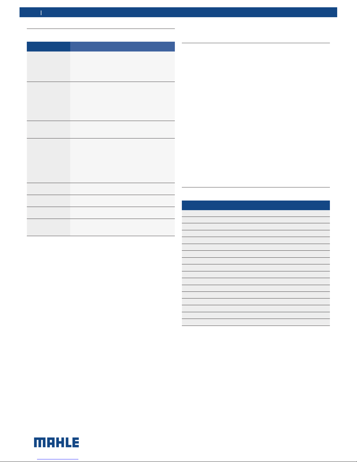
Key word Probability of
occurrence
Severity of danger
if instructions not
observed
DANGER Immediate impending
danger
Death or severe injury
WARNING Possible impending
danger
Death or severe injury
CAUTION Possible dangerous
situation
Minor injury
1.1.2 Symbols in this documentation
Symbol Designation Explanation
m
Attention Warns about possible property damage.
t
Information Practical hints and other useful information.
1.
2.
Multi-step
operation
Instruction consisting of several steps.
h
One-step
operation
Instruction consisting of one step.
Intermediate
result
An instruction produces a visible intermediate result.
Final result There is a visible final result on completion of
the instruction.
1.2 On the product
m Observe all warning notices on products and ensure they
remain legible.
h Wear protective goggles.
h Wear protective gloves.
2. Important notes
Before start up, connecting and operating MAHLE
products it is absolutely essential that the Original
instructions/owner’s manual and, in particular, the
safety instructions are studied carefully. By doing
so you can eliminate any uncertainties in handling MAHLE products and thus associated safety risks upfront; something which
is in the interests of your own safety and will ultimately help avoid
damage to the device. When a MAHLE product is handed over
to another person, not only the Original instructions but also the
safety instructions and information on its designated use must
be handed over to the person.
2.1 User group
The product may be used by skilled and instructed personnel
only. Personnel scheduled to be trained, familiarized, instructed
or to take part in a general training course may only work with
the product under the supervision of an experienced person.
All work conducted on pressurized equipment may be performed
by persons with sufficient knowledge and experience in the field
of refrigeration, cooling systems and coolants and, also be aware
of the risks involved in the use of pressurized devices.
2.2 Agreement
By using the product you agree to the following regulations:
Copyright
Software and data are the property of MAHLE or its suppliers
and protected against copying by copyright laws, international
agreements and other national legal regulations. Copying or selling of data and software or any part thereof is impermissible and
punishable; in the event of any infringements MAHLE reserves
the right to proceed with criminal prosecution and to claim for
damages.

© MAHLE
Important notes | ACX1281 | 5ACX1281 | 5 | 5
en
Liability
All data in this program is based—where possible—on manufacturer and importer details. MAHLE does not accept liability for the
correctness and completeness of software and data; liability for
damage caused by faulty software and data is ruled out. Whatever
the event, MAHLE liability is restricted to the amount for which
the customer actually pays for this product. This disclaimer of
liability does not apply to damages caused by intent or gross
negligence on the part of MAHLE.
Warranty
Any use of non-approved hardware and software will result in a
modification to our product and thus to exclusion of any liability
and warranty, even if the hardware or software has in the meantime been removed or deleted.
No changes may be made to our products. Our products may
only be used in combination with original accessories and original
service parts. Failing to do so, will render null and void all warranty claims.
This product may only be operated using MAHLE approved
operating systems. If the product is operated using an operating
system other than the approved one, then our warranty obligation
pursuant to our supply conditions will be rendered null and void.
Furthermore, we will not be held liable for damage and consequential damage incurred through the use of a non-approved
operating system.
2.3 Obligation of contractor
The contractor is obliged to ensure that all measures geared
towards the prevention of accidents, industrial diseases, laborrelated health risks are taken and measures towards making
the workplace fit for people to work in are carried out.
Specifications for electrical systems (BGV A3)
Electrical engineering in Germany is subject to the accident
prevention regulations of the trade association "Electrical Plant
and Equipment as under BGV A3 (previously VBG 4)". In all
other countries, the applicable national regulations acts or decrees are to be adhered to.
Basic rules
The contractor is bound to ensure that all electrical equipment
and operating material is set up, modified and maintained by
skilled electricians only or under the guidance and supervision
of a skilled electrician in accordance with electrical engineering
principles.
Furthermore, the contractor must ensure that all electrical equipment and operating material is operated in keeping with electrical
engineering principles.
If a piece of electrical equipment or operating material is found to
be defective, i.e. it does not or no longer complies with electrical
engineering principles, the contractor must ensure that the fault
is rectified immediately and, in the event that imminent danger
exists, also ensure that the electrical equipment or the electrical
operating material is not used.
Tests (taking Germany as an example):
y The contractor must ensure that all electrical systems and
equipment are tested by a qualified electrician or under the
guidance of a qualified electrician to ensure they are in proper
working order:
— Before starting for the first time.
— After modification or repair before starting for the first time.
— At given intervals. Set intervals such as to ensure that
faults that can be expected to occur are determined in
good time.
y The test is to take the electrical engineering principles relating
hereto into account.
y Upon request of the trade association, a test manual is to be
maintained into which specific entries are made.

© MAHLE
6 | ACX1281 | Important notesen
2.4 Safety regulations
2.4.1 ACX1281
Always carefully study and follow all the safety regulations before
using the MAHLE product.
Avoid all skin contact with the refrigerant. The low
boiling point of the refrigerant (approx. –30 °C) can
lead to frostbite. Should refrigerant come into contact with the skin, remove any moistened clothing
immediately and rinse the area of skin affected with
generous amounts of water.
y Avoid all skin contact with the UV dye. Should UV dye come
into contact with the skin, remove any moistened clothing
immediately and rinse the area of skin affected with generous
amounts of water.
y R1234yf is colorless, with weak characteristic smell and
heavier than air. It may flow into repair pits. Should refrigerant
escape, provide for sufficient ventilation (particularly in repair
pits) and leave the workshop.
Never inhale refrigerant, dye and oil vapors. The
vapors can irritate the eyes, nose and respiratory
system. If liquid refrigerant or UV dye comes into
contact with the eyes, rinse them thoroughly with
water for 15 minutes. Then obtain medical attention
even if no pain is felt.
y Never swallow UV dye. Should it be swallowed inadvertently,
never attempt to induce vomiting. Drink generous amounts of
water and obtain medical attention.
y Before connecting the ACX1281 to a vehicle air conditioning
system or an external refrigerant bottle, make sure the quickrelease couplings are not leaking. Only ever use external
refrigerant bottles provided with safety valves and certified
inline with the applicable standards.
y Before switching off the ACX1281, make sure all charging
and drainage operations have been completed. This prevents
damage to the unit and reduces risk of refrigerant escaping
into the environment.
Never use compressed air with R1234yf. Certain mixtures of air and R1234yf are highly flammable. Such
mixtures are a potential hazard and may lead to fire or
explosions and thus cause damage or injury.
y Refrigerant extracted from a vehicle air conditioning system
may be contaminated with moisture, lubricant, dirt and traces
of other gases.
y The ACX1281 is provided with a refrigerant identification system
designed to prevent contamination with other refrigerants.
y If the refrigerant has been contaminated by being mixed with
other gases, remove the contaminated refrigerant and add
fresh R1234yf before using the ACX1281 for A/C service.
y R1234yf is not to be used in areas in which there is a danger
of explosion. Fire, open flames and smoking are prohibited.
Welding and soldering are not permitted.
y The ACX1281 unit should not be exposed to excess moisture
or be operated in wet areas.
y High temperatures and UV radiation may chemically separate
R1234yf. The resultant products can cause coughing and
nausea.
y R1234yf is not to be mixed with other refrigerants. The mix-
ing of refrigerants could damage the vehicle air conditioning
system.
If high-voltage components or high-voltage wires are
handled incorrectly, there is a risk of fatal injury from
high voltage and the possible transmission of current
through the body.
y De-energizing is only to be performed by a qualified electri-
cian, a qualified electrician for specific tasks (hybrid) or a
power systems engineer.
y Work on vehicles with high-voltage components is only ever
to be performed in a safe, de-energized condition by persons
with the minimum qualification "Trained to perform electrical
work".
y Even after deactivating a high-voltage vehicle electrical sys-
tem, the high-voltage battery may still be live.
y Operating condition cannot be established from any running
noise, as the electric machine is silent when stationary.
y In gear positions "P" and "N" the engine or electric motor
may start spontaneously depending on the charge of the
high-voltage battery.
y Never open or damage high-voltage batteries.
y On vehicles that have been in an accident, never touch high-
voltage components or exposed high-voltage wires before
deactivating the high-voltage vehicle electrical system.
y The ACX1281 must be constantly monitored when in opera-
tion. Never leave the ACX1281 unattended when in operation.
y Vehicle A/C service using the ACX1281 must be prepared and
implemented such that the vehicle air conditioning system
circuit does not have to be opened (for example by removing
the radiator or engine).
© MAHLE
Important notes | ACX1281 | 7ACX1281 | 7 | 7 en
y Position the ACX1281 on all four wheels on a flat, vibration-
proof surface so that proper operation of the scales is guaranteed.
y The ACX1281 can be secured in position by locking the caster
brake.
y The ACX1281 must always be transported in its operating
position. Never lay the ACX1281 on its side, as oil could then
escape from the vacuum pump or the built in compressor
could be damaged.
y There are no additional safety systems for protecting the
ACX1281 against damage resulting from natural catastrophes.
y Never remove any components from inside the ACX1281
except for maintenance or repair purposes.
y Follow the pertinent legal regulations or directives to ensure
safe handling of pressurized devices.
y We recommend calibrating the scales at least once per year.
Contact customer service for calibration of the scales.
y The ACX1281 must be subjected to regular maintenance by
service personnel or authorized agents to ensure the safety
of the unit.
y Disconnect power before performing any maintenance or
service to unit.
y Never perform any maintenance work which is not expressly
recommended in this manual. Contact customer service if
components have to be replaced other than in the course of
maintenance work.
y ACX1281 must be connected to a properly grounded electri-
cal connection.
y If there is damage to the ACX1281, terminate usage immedi-
ately and contact customer service.
y The service hoses and service quick-release couplings must
be regularly checked for wear and replaced if damaged.
y The ACX1281 must be operated in an environment cor-
responding to the directive BGR 157 with respect to the
exchange of air.
y Observe local laws or directives as to ensure the safety of the
pressurized device.
y For safety reasons it is advisable to use a residual current
operated circuit breaker (rccb) with the following specifications:
Parameters Specification
Rated voltage 110 VAC ± 10%
Rated frequency 50/60Hz
Rated current 10A
Rated tripping current 30mA
Tripping switch C
2.4.2 Refrigerant identification unit
y Inspect the outside diameter of the white sample filter element
before and after each use of this unit. As soon as red spots
begin to appear on any portion of the white element outside
diameter, the filter requires replacement. Failure to replace the
filter when so indicated may result in damage to the identification unit (out of warranty).
y Never use a test hose other than those approved for use with
the Identifier.
y Never connect the Identifier to any refrigerant source that
exceeds 300 psi pressure.
© MAHLE
8 | ACX1281 | Product descriptionen
3. Product description
3.1 Application
ACX1281 is suitable for vehicles with a conventional engine as
well as for hybrid and electric vehicles. ACX1281 features all the
functions required for vehicle A/C service.
The following functions can be implemented:
y Refrigerant recovery and recharging.
y Refrigerant conditioning.
y Vacuum generation.
y Flushing.
y Refrigerant identification.
m The ACX1281 can only be operated with R1234yf. The
ACX1281 is not to be used for service work on vehicles with
air conditioning systems employing refrigerants other than
R1234yf, as this will cause damage. Prior to A/C service
check the type of refrigerant used in the vehicle air conditioning system.
3.2 Scope of delivery
Description
Service hose (high pressure)
Service hose (low pressure)
Quick-release coupling (high pressure)
Quick-release coupling (low pressure)
Used oil bottle
Original instructions
Quick manual
Roll of paper for printer
Adapter (external bottle) - US Acme 1/2 LH
Calibration check ball
Inline filter set (2x)
Refrigerant identification unit
Flushing kit
Hex key for handle installation
Safety goggles
Protective gloves
Dust cover
2.5 Safety devices
Description Function
Housing switch If one of the covers is removed from the ACX1281,
all operations are terminated and the ACX1281 is
disabled until the removed cover has been re-attached to the ACX1281.
Service door switch If the service door of the ACX1281 is removed, the
ACX1281 stops all processes and starts service
mode. The built-in ventilation fan remains in operation to ensure that any R1234yf vapors which may
have accumulated in the ACX1281 housing (e. g.
on replacing the dry filter) are extracted from the
service area.
Air flow sensor The ACX1281 contains an air flow sensor which
detects whether or not there is a sufficient flow of
air in the housing of the ACX1281.
Safety shut-off
valves of internal
bottle:
The ACX1281 is provided with automatic safety shut-off valves at the internal refrigerant bottle.
Whenever a process is interrupted or covers/service doors have been removed, the valves of the internal bottle close prevent R1234yf refrigerant escaping from the internal refrigerant bottle.
The safety shut-off valves are closed when the
ACX1281 is not active.
Pressure switch Switches the compressor off if the normal operat-
ing pressure is exceeded.
Safety valve The safety valve opens if the design pressure is ex-
ceeded.
Circuit breaker Interrupts the power supply if overcurrent is applied
to the ACX1281.
Vents The ACX1281 is provided with vents in the bottom
of the housing to ensure the exchange of air even
when switched off.
© MAHLE
Product description | ACX1281 | 9ACX1281 | 9 | 9 en
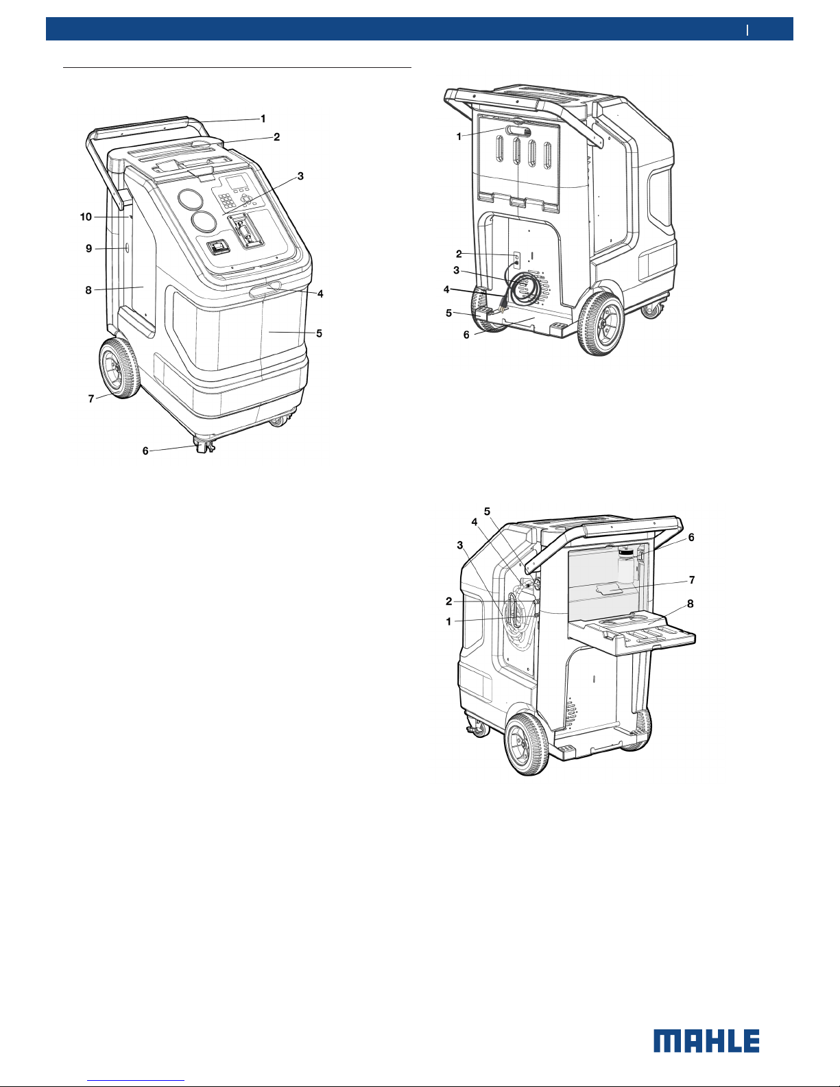
Fig. 2: Rear view
1 Service door for used oil and vacuum pump oil
2 Power supply cable inlet, circuit breaker
3 Fan
4 Power supply cable
5 Kick plate
6 Flush device storage shelf / spare refrigerant bottle storage
Fig. 3: Left-rear view
1 Low-side parking/flush adapter
2 High-side parking/flush adapter
3 Service hose
4 Service hose connections
5 Main switch
6 Used oil load cell and bottle
7 Vacuum pump oil fill access port
8 Service door for oil bottles and vacuum pump
3.3 Description of unit
Fig. 1: Front view
1 Rear handle and grip
2 Tool tray and storage
3 Display and operating unit
4 Front handle
5 ACX1281 front housing
6 Locking caster
7 Rear wheel
8 Service door
9 Vacuum pump sight glass viewing window
10 USB port
© MAHLE
10 | ACX1281 | Product descriptionen
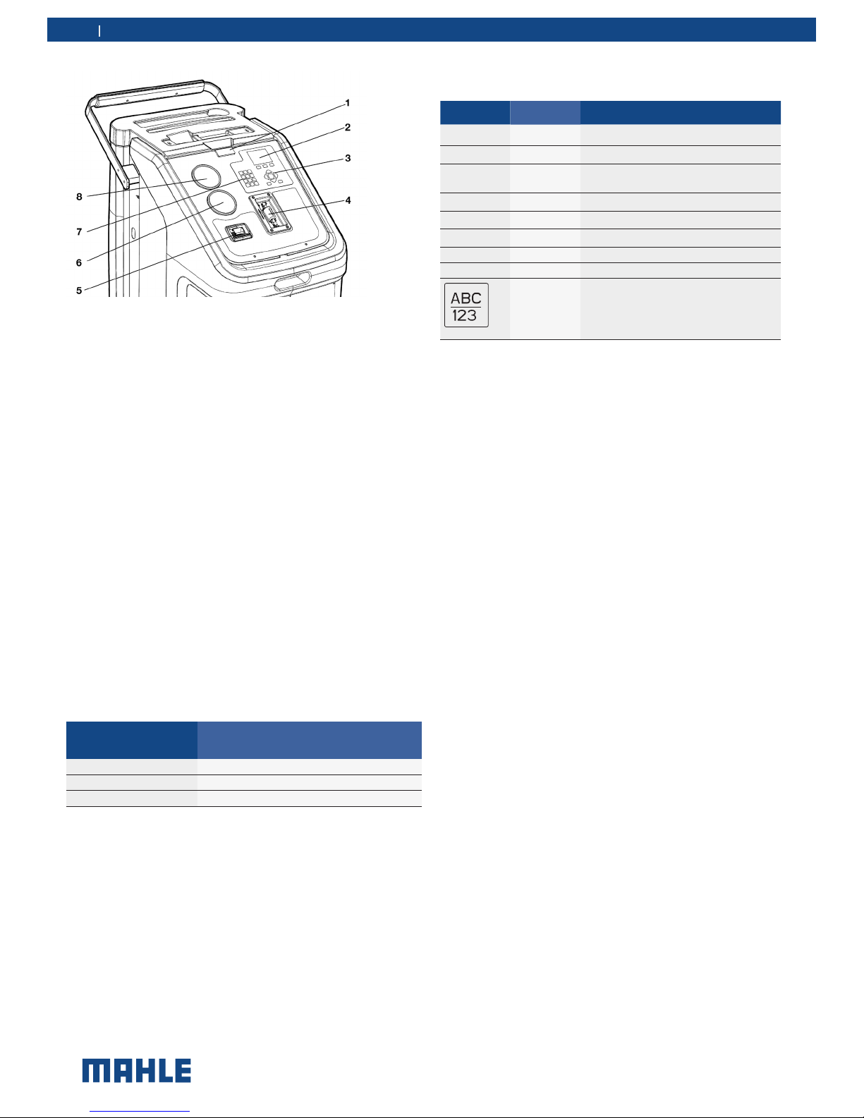
Fig. 4: Display and operating unit
1 Status and warning light
2 LCD
3 Selection and function keys
4 Refrigerant identifier
5 Printer
6 Low-pressure gauge
7 Input keys
8 High-pressure gauge
The pressure gauges (Fig. 4, Pos. 6, 8) of the display and operating unit are used to monitor the pressure during the individual
vehicle A/C service phases. The status of the various service
phases during maintenance is displayed on the multicolor LCD
screen (Fig. 4, Pos. 2). The necessary entries are made by way
of the input keys (Fig. 4, Pos. 7) on the keypad.
The selection and function keys (Fig. 4, Pos. 3) on the keypad are
used to control the operator interface menu options.
The status and warning light (Fig. 4, Pos. 1) indicates the service
status:
Status and warning
light display color
Maintenance status
Red light Error/warning
Flashing green Operation in progress
Green light Operation completed/Attention Operator
If a situation arises where the unit software requires updated,
MAHLE has a USB stick available for updating the ACX1281
software. The USB stick can be inserted in the USB socket to
perform updating of the firmware/software.
t Refer to Section 8.9 for detailed information on the
software updating procedure.
3.3.1 Selection and function keys
Keys Name Function
O
OK Confirm and store
Function depends on current menu
Back
Cancel
Back one menu level or cancel
or
Up or down control
or
Right or left control
Enter Confirm and store
C Delete Deletes character to left of cursor
i Information Show current data
Switching between number and letter
input. Current mode is shown at bottom right of screen.
Various functions are assigned to the function keys in the
ACX1281 software. The functions of the keys are defined in the
menu line of the ACX1281 software.
3.3.2 Input keys
The input keys can be used to enter letters, numbers and special
characters in the input boxes. If a key is pressed several times
in succession in the input box, all the characters which can be
used for this are displayed.
© MAHLE
Product description | ACX1281 | 11ACX1281 | 11 | 11 en
3.3.3 Printer
t Service reports can be printed out.
m Protect thermal printer paper against direct sunlight, heat,oils,
greases, tanning agents and materials containing plasticizers
(e.g. PVC folders).
Fig. 5: Printer
1 Cover
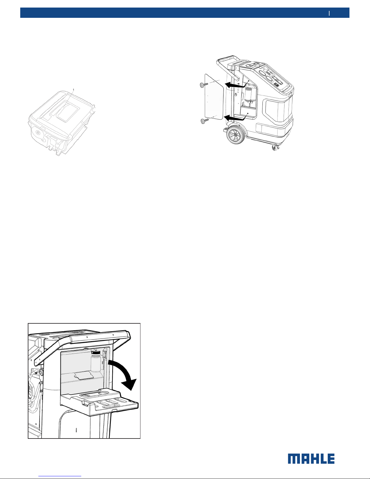
3.3.4 Service doors
t There are two service doors: One on the left side and one
on the rear of the housing.
t Tools can be placed on the upper cover.
t The left side service door is fitted with a contact switch. If the
service hatch is removed, the ACX1281 switches automatically to maintenance mode and will not provide A/C service
functions. The ACX1281 returns to the main menu on refitting
the service door.
t The service door on the side provides access to the the internal
refrigerant bottle, and the filter drier.
t The service door on the rear permits access to the Vacuum
pump oil fill/drain and used oil.
Fig. 6: Opening service door on back
To open the service door on the cover, remove the two locking
screws and take out the service door.
Fig. 7: Removing service door
t The built-in ventilation fan of the ACX1281 remains in opera-
tion when the ACX1281 switches to service mode to remove
potentially flammable R1234yf refrigerant vapors which may
have accumulated in the housing during A/C service.
m Never attempt to operate the ACX1281 without service doors,
as this would make the working area dangerous. The housing
of the ACX1281 was designed with a built-in ventilation fan
to prevent the accumulation of potentially flammable R1234yf
refrigerant vapors.
 Loading...