

MAHLE ACX1180 Original Instructions Manual
MAHLE ACX1180
Original instructions
EN
AC Service Units
2 | ACX1180 | en
Content s
1 . Sym bols use 4
1.1 In the documentation 4
1.1.1 Warning notices—Structure and meaning 4
1.1.2 Symbols in this documentation 4
1.2 On the product 4
2. Important notes 4
2.1 User group 4
2.2 Agreement 4
2.3 Obligation of contractor 5
2.4 Safety regulations 6
2.4.1 ACX1180 6
2.4.2 Refrigerant identication unit 7
2.5 Safety devices 7
3. Product description 8
3.1 Application 8
3.2 Scope of delivery 8
3.3 Description of unit 9
3.3.1 Selection and function keys 10
3.3.2 Input keys 10
3.3.3 Printer (Optional) 11
3.3.4 Service doors 11
3.3.5 Oil bottles 12
3.3.6 Service quick-release couplings 12
3.3.7 Inline lters 13
3.3.8 Locking caster brakes 13
3.3.9 Power supply cable and switch 13
3.4 Refrigerant identication unit (Optional) 13
3.4.1 Delivery 13
3.5 Functional description 14
4. Commissioning 15
4.1 Removing transportation packaging 15
4.2 Attaching handle 15
4.3 ACX1180 16
4.3.1 Setting language 16
4.3.2 Setting date and time 16
4.3.3 Activating / deactivating
printer, buzzer 16
4.4 Setup 16
4.4.1 Selectable Options 16
4.4.2 Default Values 17
4.4.3 Maintenance Options 17
4.4.4 Total Capacities 17
4.6 Filling internal refrigerant bottle 18
4.5 Checking type of connection of
external refrigerant bottle 18
5. A/C service preparation 19
6. Operation 20
6.1 Service phases 20
6.2 A/C Database 20
6.3 Refrigerant identication unit 20
6.3.1 Refrigerant analysis 20
6.4 Automatic A/C service 21
6.5 Manual A/C service 21
6.6 Automatic/manual vehicle A/C
service overview 22
6.6.1 Recovery 22
6.6.2 Vacuum 22
6.6.3 Charging with refrigerant 22
6.7 Flushing after changing type of oil 22
6.8 Setting service parameters 22
6.9 Non-condensable gases 23
© MAHLE
7. Maintenance 24
7.1 Maintenance interval 24
7.2 Calibration of refrigerant scale 24
7.3 Calibration check 24
7.4 Replacing inline lters 24
7.5 Vacuum pump 25
7.5.1 Changing vacuum pump oil 25
7.6 Combo lter 26
7.6.1 Changing Combo-Filter 26
7.6.2 Resetting lter replacement interval 26
7.7 Software update 27
7.8 Replacing printer paper 27
7.9 Replacing white sample lter
(Refrigerant ident ication unit) 27
7.10 Resetting the circuit breaker 27
7.11 System information 27
7.12 Spare and wearing parts 28
7.12.1 ACX1180 28
7.12.2 Refrigerant identication unit 28
8. Disposal 28
8.1 Disposal of electronic p art s 28
8.2 Disposal of LCD screen 28
8.3 Disposal of refrigerant s, UV dye,
lubricants and oils 28
8.4 Disposal of combo lter 28
| ACX11 80 | 3ACX1180 | 3 | 3 en
9. Technical data 29
9.1 ACX1180 29
9.2 Electromagnetic compatibility 29
10. Glossary 29
11. Notes 30
© MAHLE
4 | ACX1180 | Symbols useen
1. Symbols use
1.1 In the documentation
1.1.1 Warning notices—Structure and meaning
Warning notices warn of dangers to the user or people in
the vicinity. Warning notices also indicate the consequences
of the hazard as well as preventive action. Warning notices
have the following structure:
Warning
symbol
The key word indicates the likelihood of occurrence and t he
severity of the hazard in the event of non- observance:
Key word Probability of
DANGER Im m e d i at e impending
WARNING Possible impending
CAUTION Possible dangerous
1.1.2 Symbols in this documentation
KEY WORD – Nature and source of hazard!
Consequences of hazard in t he event of failure to observe action and information given.
h
Hazard p revent ion act ion and information.
occurrence
danger
danger
situation
Severity of danger
if instructions not
observed
De at h or s e ve r e injury
De at h or s e ve r e injury
M i nor injury
2. Important notes
Before start up, connecting and operating
MAHLE products it is absolutely essential that
the Original instructions/owner’s manual and,
in particular, the safety inst ruc tions are studied
carefully. By doing so you can eliminate any uncertainties in
handling MAHLE products and thus associated safety risks
upfront; something which is in the interests of your own
safety and will ultimately help avoid damage to the device.
When a MAHLE product is handed over to another person,
not only the Original instructions but also the safety instructions and information on its designated use must be handed
over to the person.
2.1 User group
The product may be used by skilled and instructed
personnel only. Personnel scheduled to be trained,
familiarized, instructed or to take part in a general
training course may only work with the product under
the supervision of an experienced person.
All work conducted on pressurized equipment may be
performed by persons with sufficient knowledge and
experience in the field of refrigeration, cooling systems
and coolants and, also be aware of the risks involved in
the use of pressurized devices.
Symbol Designat ion Expl anation
m
t
1.
2.
h
Attention Warns about possible property d amage.
Information Practical hints and other
Multi- step
operation
One-step
operation
Intermediate
result
Final result There is a visible final result on
useful informat ion.
Instruction consisting of several steps.
Instruction consisting of one step.
An instruction prod uces a visible
intermediate result.
completion of the instruction.
1.2 On the product
Observe all warning notices on products and ensure they
m
remain legible.
h
Wear protective goggles.
h
Wear protective gloves.
2.2 Agreement
By using the product you agree to the following regulations:
Copyright
Softw are and data are the property of MAHLE or its suppliers and protected against copying by copyright laws,
international agreements and other national legal regulations. Copying or selling of data and software or any part
thereof is impermissible and punishable; in the event of any
infringements MAHLE reserves the right to proceed with
criminal prosecution and to claim for damages.
© MAHLE

Sy m b o ls u s e | ACX 1 1 8 0 | 5ACX1180 | 5 | 5 en
Liability
All data in this program is based—where possible—on
manufacturer and importer details. MAHLE does not accept
liability for the correctness and completeness of software
and data; liability for damage caused by faulty software and
data is ruled out. Whatever the event, MAHLE liability is restricted to the amount for which the cust omer act ually pays
for this product. This disclaimer of liability does not apply to
damages caused by intent or gross negligence on the part
of MAHLE.
War rant y
Any use of non-approved hardware and software will result
in a modification to our product and thus to exclusion of any
liability and warranty, even if the hardware or software has
in the meantime been removed or deleted.
No changes may be made to our products. Our products
may only be used in combination with original accessories
and original service parts. Failing to do so, will render null
and void all warranty claims.
This product may only be operated using MAHLE approved operating systems. If the product is operated using
an operating system other than the approved one, then
our warranty obligation pursuant to our supply conditions
will be rendered null and void. Furthermore, we will not be
held liable for damage and consequential damage incurred
through the use of a non-approved operating system.
2.3 Obligation of contractor
The contrac tor is obliged to ensure that all measures geared
towards the prevention of accidents, industrial diseases,
labor-related health risks are taken and measures towards
making the workplace fit for people to work in are carried
out.
Basic rules
The contractor is bound to ensure that all elect ric al equipment and operat ing material is set up, modified and maintained by skilled electricians only or under the guidance
and supervision of a skilled electrician in accordance with
elect ric al engineering principles.
Furthermore, the cont ractor must ensure that all electrical
equipment and operating material is operated in keeping
with elec trical engineering principles.
If a piece of electrical equipment or operating material is
found to be defective, i.e. it does not or no longer complies with electrical engineering principles, the contractor
must ensure that the fault is rectified immediately and, in
the event that imminent danger exists, also ensure that the
elect ric al equipment or the elec trical operating material is
not used.
Tests:
y
The contractor must ensure that all electrical systems
and equipment are tested b y a qualified electrician or
under the guidance of a qualified electrician to ensure
they are in proper working order:
—
Before starting for the first time.
—
After modification or repair before starting for the
first time.
—
At given intervals. Set intervals such as to ensure
that faults that can be expected to occur are determined in good time.
y
The test is to take the elect ric al engineering principles
relating hereto into account.
y
Upon request of t he trade association, a test manual is
to be maintained into which specific entries are made.
© MAHLE

6 | ACX1180 | Symbols useen
2.4 Safety regulations
2.4.1 ACX1180
Always carefully study and follow all the safety regulations
before using the MAHLE product.
Avoid all skin contact with the refrigerant. The
low boiling point of the refrigerant (approx.
–30°C) can lead to frostbite. Should refrigerant
come into contact with the skin, remove any
moistened clothing immediately and rinse the
area of skin affected w it h generous amounts of
water.
y
Avoid all skin contact with the UV dye. Should UV dye
come into contact w ith the skin, remove any moistened
clothing immediately and rinse the area of skin affec ted
with generous amounts of water.
y
R134a is colorless, with weak characteristic smell and
heavier than air. It may flow into repair pits. Should refrigerant escape, provide for sufficient ventilation
(particularly in repair pits) and leave the workshop.
Never inhale refrigerant, dye and oil vapors. The
vapors can irritate the eyes, nose and respiratory
system. If liquid refrigerant or UV dye comes into
contac t with the eyes, rinse them t horoughly
with water for 15 minutes. Then obtain medical
attention even if no pain is felt.
y
Never swallow UV dye. Should it be swallowed inadvertently, never attempt to induce vomiting. Drink generous
amounts of water and obtain medical attention.
y
Before connecting the ACX1180 to a vehicle air conditioning system or an external refrigerant b ottle, make
sure the quick-release couplings are not leaking. Only
ever use external refrigerant bottles provided with safety
valves and certified inline with the applicable standards.
y
Before switching off the ACX1180, make sure all charging and drainage operations have been completed. This
prevents damage to the unit and reduces risk of refrigerant escaping into the environment.
Never use compressed air with R134a. Certain
mixtures of air and R134a are highly flammable.
Such mixtures are a potential hazard and may
lead to fire or explosions and thus cause damage or injury.
y
Refrigerant ext racted from a vehicle air conditioning
system may be contaminated with moisture, lubricant,
dirt and traces of other gases.
y
The ACX1180 is provided with a refrigerant identific ation
system designed to prevent contamination wit h other
refrigerants.
y
If the refrigerant has been cont aminated by being mixed
wit h other gases, remove t he cont aminated refrigerant
and add fresh R134a before using the ACX1180 for A/C
service.
y
R134a is not to be used in areas in which there is a
danger of explosion. Fire, open flames and smoking are
prohibited. Welding and soldering are not permitted.
y
y
The ACX1180 unit should not be exposed to excess
moisture or b e operated in wet areas.
y
R134a is not to be mixed with other refrigerants. The
mixing of refrigerants could damage the vehic le air conditioning system.
If high-voltage components or high-voltage
wires are handled incorrectly, there is a risk of
fatal injury from high voltage and the possible
transmission of current through the body.
y
De-energizing is only to be performed by a qualified
elect ric ian, a qualified electrician for specific tasks (hybrid) or a power systems engineer.
y
Work on vehicles with high-voltage components is only
ever to be performed in a safe, de-energized condition
by persons with the minimum qualification "Trained to
perform electrical work".
y
Even after deactivating a high-volt age vehicle elect ric al
system, the high-voltage battery may still be live.
y
Operating condition cannot be established from any
running noise, as the electric machine is silent when
stationary.
y
In gear positions "P" and "N" the engine or electric
motor may start spontaneously depending on the charge
of the high-voltage battery.
y
Never open or damage high-voltage batteries.
y
On vehic les t hat have been in an acc ident, never touch
high-voltage components or exposed high-voltage
wires before deactivating high-voltage vehicle electrical
system.
y
The ACX1180 must be constantly monitored when in
operation. Never leave the ACX1180 unattended when in
operation.
y
Vehicle A/C service using the ACX1180 must be prepared and implemented such that the vehicle air conditioning system circuit does not have to b e opened (for
example by removing the radiator or engine).
y
Position the ACX1180 on all four wheels on a flat,
vibration-proof surf ace so t hat prop er operation of the
scales is guaranteed.
y
The ACX1180 can be secured in position by locking the
caster brake.
y
The ACX1180 must always be transported in its operating position. Never lay the ACX1180 on its side, as oil
could then escape from the vacuum p ump or the b uilt in
compressor could be damaged.
© MAHLE

y
There are no additional safety systems for protecting the
ACX1180 against damage resulting from natural catastrophes.
y
Never remove any components from inside the ACX1180
except for maintenance or repair purposes.
y
Follow the pertinent legal regulations or directives to
ensure safe handling of pressurized devices.
y
We recommend calibrating t he scales at least once p er
year. Contact customer servic e for calibration of the
scales.
y
The ACX1180 must be subjected to regular maintenance
by service personnel or authorized agents to ensure the
safety of the unit.
y
Disconnect power before performing any maintenance or
service to unit.
y
Never perform any maintenance work which is not expressly recommended in this manual. Cont act customer
servic e if component s have to be replaced ot her t han in
the course of maintenance work.
y
ACX1180 must be connected to a properly grounded
electrical connection.
y
If there is damage to t he ACX1180, terminate usage immediately and c ontact customer servic e.
y
The service hoses and service quick-release couplings
must be regularly checked for wear and replaced if damaged.
y
The ACX1180 must be operated in an environment that
will provide at least four air changes per hour.
y
Observe local laws or directives as to ensure the safety
of the pressurized device.
y
For safety reasons it is advisable to use a residual current operated circuit b reaker (rccb) with the following
specifications:
Sy m b o ls u s e | ACX 1 1 8 0 | 7ACX1180 | 7 | 7 en
y
Inspect the test hose before and after each use of the
unit. Immediately replace the hose if it ap pears cracked ,
obstructed, or fouled with oil.
y
Never use a test hose other than those approved for use
with the Id ent ifier.
y
Never c onnect t he Id ent ifier to any refrigerant sourc e that
exceeds 300 psi pressure.
2.5 Safety devices
Description Function
Pressure switch Switches the compressor off if the normal
Safety valve The safety valve opens if the design pressure
Circuit Breaker Interrupt s the power supply if overcurrent is
Vents The ACX1180 is provided with vents
operating pressure is exc eeded .
is exceeded.
applied to the ACX1180.
in the bottom of t he housing to ensure t he
exchange of air even when switched off.
Parameters Specification
Rated voltage 120 VAC ± 10 %
Rated frequency 50/60 Hz
Rated current 10 A
Rated tripping current 30 mA
Tripping switch C
• Avoid using an extension cord with the unit. If necessary,
use a good condition (three wire grounded, #14AWG or
larger) extension cord of the shortest possible length. In
addtion, the current drawn by all devices connected to
the wall socket must not exc eed 15A total.
2.4.2 Refrigerant identification unit
y
Inspect the outside diameter of the white sample filter
element before and after each use of this unit. As soon
as red spots begin to appear on any portion of the white
element outsid e diameter, the filter requires replacement.
Failure to replace t he filt er when so indicated may result
in damage to the identification unit (out of warranty).
y
This unit requires connection of the sample fitting to the
LP sid e port of the source vehicle or refrig erant cylinder.
Connection of the test hose to the high, or liquid, port of
the source vehicle or refrigerant bottle will result in damage to the unit (out of warranty).
© MAHLE
8 | ACX1180 | Product descriptionen
3. Product description
3.1 Application
ACX1180 is suit able for vehicles with a c onventional engine
as well as for hyb rid and electric vehicles. ACX1180 features
all the functions required for vehicle A/C service.
The following functions can be implemented:
y
Refrigerant recovery and recharging.
y
Vacuum generation.
y
Flushing.
y
Refrigerant identification.
m
The ACX1180 can only be operated with R134a. The
ACX1180 is not to be used for service work on vehicles
with air conditioning systems employing refrigerants
other than R134a, as this will cause damage. Prior to
A/C service check the type of refrigerant used in the
vehicle air conditioning system.
3.2 Scope of delivery
Descr iption
Handle
Service hose (high pressure)
Service hose (low pressure)
Quick-release coupling (high pressure)
Quick-release coupling (low p ressure)
Used oil bottle
Original instructions
Quick manual
Adapter (external bott le)
US Acme 1/2
Calibration check ball
Inline filter set (2x)
Refrigerant id entifier (op tional it em)
Printer (optional item)
Fresh oil bot tle ("C" version units only)
1)
May be included in delivery, depending on the version ordered
© MAHLE
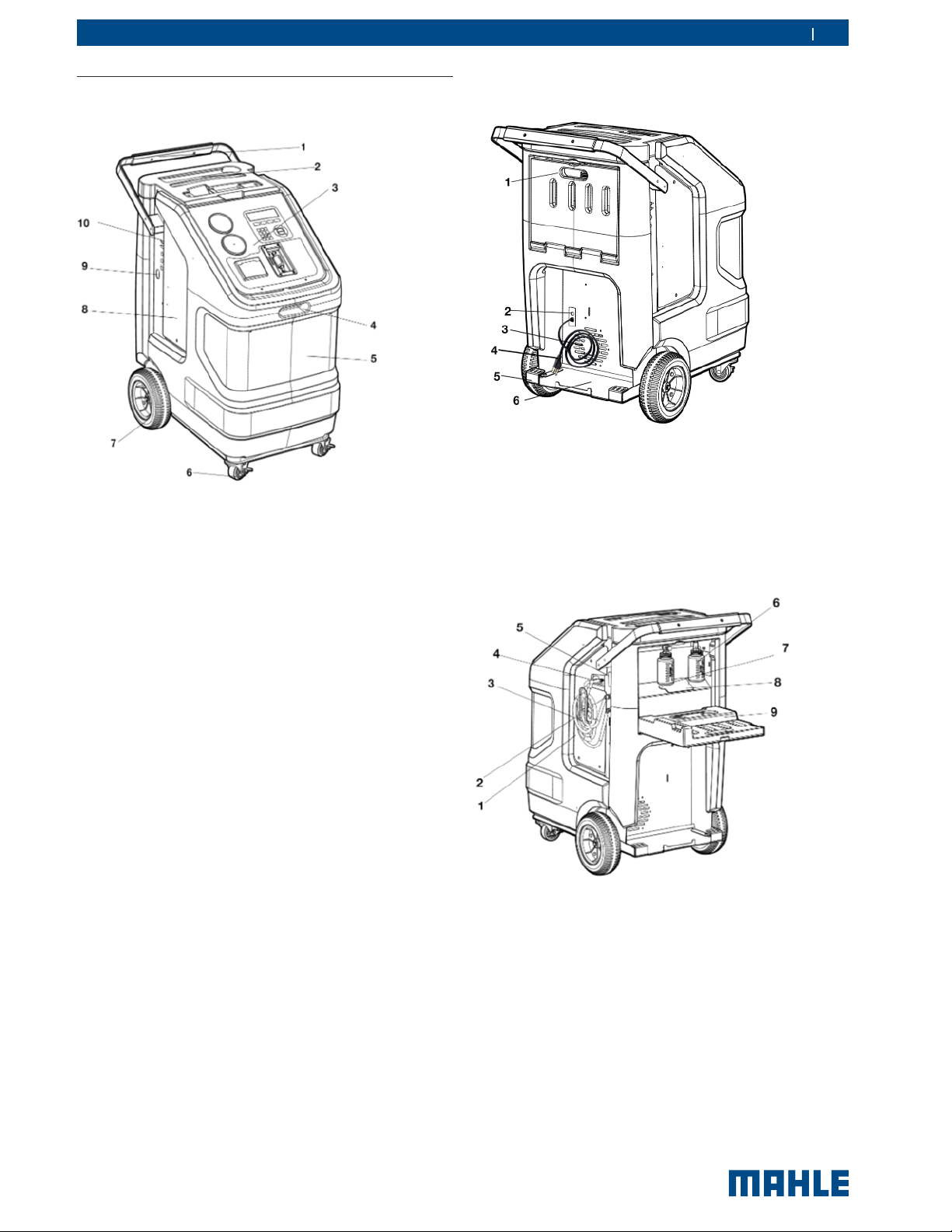
3.3 Description of unit
Fig. 1: Front view
1 Rear handle and grip
2 Tool t ray and sto rage
3 Display and operating unit
4 Front handle
5 ACX1180 front housing
6 Locking caster
7 Rear wheel
8 Service door
9 Vacuum pump sight glass viewing window
10 USB port
Product description | ACX1180 | 9ACX1180 | 9 | 9 en
Fig. 2: Rear view
1 Service door for used oil and vacuum pump oil
2 Power supply cable inlet, circuit breaker
3 Fan
4 Power supply cable
5 Kick plate
6 Spare refrigerant bot tle/Flush devic e storage shelf
Fig. 3: Left-rear view
1. Low -side p arking/ush adapter (depend ing on unit model)
2. High-side p arking/ush adapter (depending o n unit mo del)
3. Service hose
4. Service hose connections
5. Power switch
6. Used oil bottle
7. Vacuum pump oil ll access port
8. Service door for oil bottles and vacuum pump
© MAHLE

10 | ACX1180 | Product descriptionen
3.3.1 Selection and function keys
Keys Name Function
Yes Confirm and store
No Stop procedure, Exit menu
Fig. 4: Display and operating unit
1 TechALERT mounting area (Accessory)
2 LCD
3 Selection and function keys
4 Refrigerant identier (Accessory)
5 Printer (Accessory)
6 Low-p ressure gauge
7 Input keys
8 High-pressure gauge
The pressure gauges (Fig. 4, Pos. 6, 8) of the display and
operating unit are used to monitor the pressure during the
individual vehicle A/C service phases. The status of the
various service phases during maintenance is displayed on
the multicolor LCD screen (Fig. 4, Pos. 2). The necessary
entries are made by way of the input keys (Fig. 4, Pos. 7) on
the keypad.
The selection and function keys (Fig. 4, Pos. 3) on the
keyp ad are used to control the operator interface menu
options.
or
or
Automatic Takes op erator direc tly to Automatic p roc ess
Recycle Takes operator direc tly to Recycle process
Vacuum Takes operator directly to Vacuum process
Charge Takes operator directly to Charge process
Unit of
Measure
Up or down control
Right or left control
Toggle units displayed on LCD display.
Various functions are assigned to the function keys in the
ACX1180 software. The functions of the keys are defined in
the menu line of the ACX1180 software.
3.3.2 Input keys
The inp ut keys can be used to enter letters, numbers and
special characters in the input boxes. If a key is pressed
several times in succession in the input box, all the
characters which can be used for this are displayed.
t
Pressing the #4 key when at the main menu provides
quick access to the Language selection screen. Follow
on-screen instructions to change language.
t
Pressing the #7 key when at t he main menu does an
automatic Oil Drain process.
MAHLE supplies a USB stick for updating the ACX1180
software. If required, the USB stic k c an be inserted in the
USB socket to perform updating of the firmware/software.
t
Refer to Section 7.9 for detailed information on the
software updating procedure.
© MAHLE
 Loading...