

Page 1

© 2016 Mahindra REVA Electric Vehicles Ltd (MREVA), Bangalore. All rights reserved. This Manual
cannot be reproduced or copied, in whole or par t without the written permission of MREVA, Bangalore.
Released by:
Technical Hub Mahindra Reva
Electric Vehicle Pvt. Ltd.
Rev 1 - 2016
SAFETY, ROADSIDE ASSISTANCE &
MAN No: 00340
FIRST RESPONDERS MANUAL
Models applicable: e o City & Tech X
2
Page 2

Page 3

FOREWORD
This user manual explains on safety, road assistance and first responders operations with related
information including warnings, cautions that needs to be followed while providing support and
assistance to occupants.
This is an electric vehicle powered by battery pack. Improper and wrong operations / techniques /
procedures while providing support may cause serious personal injury or result in death.
Please read this manual carefully in advance for understanding the features of the vehicle and to provide
assistance in incidents involving this vehicle. Following recommended given procedures are the best
practices for helping in providing support with required informations.
1
Page 4

2
2.0 IMPORTANT INFORMATION
Safety symbols
Please carefully read, understand & follow the safety symbols / instructions in this manual.
Legend of the symbols
You will see various safety symbols in this manual & are used in the below following ways. Obey all safety
messages with words DANGER, WARNING, CAUTION & NOTE having special meanings.
This indicates a hazardous situation which, if not avoided, will result in death or serious personal injury.
DANGER
Indicates the presence of a hazard situation that could cause death or serious personal injury.
All information, illustrations and specifications in this ‘Manual’ were in effect at the time of printing.
Mahindra Reva Electric Vehicles Ltd. in the course of product development reserves the right to discontinue
or change / modify information /specifications or design at any time without notice, without any liability &
obligation whatsoever.
WARNING
Indicates a potentially hazardous situation which, if not avoided, may result in minor or moderate injury.
CAUTION
Note indicates important information on vehicle’s use & maintenance to which particular attention should be
paid.
The symbol below indicates NO , Do Not do this or Never
Note
CAUTION
Caution without safety alert indicates a potentially hazardous situation which, if not avoided, may result in
property damage.
Copyright reserved 03 2016 REV -R0
! In case if you use any medical electric devices like implantable cardiac pace maker or cardio vascular
defibrillator, do check the electric medical device supplier / manufacturer on concerns of effects that
EV charging or discharging system on implanted such devices prior to their operation.
! It is also advised not to stay in the vehicle or access vehicle during charging as it may effect function
of electric medical devices and could result in personal injury or death.
! Also make sure that there is no foreign particles or water traces in charge plug or port as any of
these can result in electric short circuit or shock causing serious injury or death. Hence do not
touch metal contacts on the cable or plug.
! Ensure that power socket is switched off before accessing charge cable.
! Do not handle the charge cable or port with wet hands as it may cause electric shock resulting to
injury or death.
WARNING
Page 5

1.0 Foreword.................................................................................
2.0 Important information............................................................
3.0 About Mahindra Reva Electric Vehicle....................................
4.0 Vehicle identification number.................................................
5.0 Vehicle specification...............................................................
6.0 High voltage components identification and location............
7.0 Emergency response steps.....................................................
8.0 Identifying of high voltage system status................................
9.0 Vehicle battery disconnect......................................................
10.0 Operational procedures..........................................................
11.0 Fuse box details......................................................................
12.0 Lubricant chart.......................................................................
13.0 Personal protective equipments and insulated tools.............
14.0 Accessing occupants and rescue............................................
15.0 Process for shutting down high voltage system......................
16.0 Handling damaged car at accident location............................
17.0 Airbag access, deployment and dismantling..........................
18.0 Road side assistance...............................................................
19.0 Changing flat tyre...................................................................
20.0 Caution note...........................................................................
01
02
05
06
06
07
09
10
12
13
14
14
15
16
18
19
20
22
24
26
3
CONTENTS
Page 6

4
Page 7

3.0 ABOUT MAHINDRA REVA ELECTRIC VEHICLE
5
This is an electric vehicle that is powered by high voltage battery pack. It has two type of battery used for
its operation. Car has 72V electric system with battery that powers drive system and other is a 12 volts
auxiliary battery that powers 12Volt accessories and other control units. The 72V battery pack is housed
in the battery compartment located beneath front seats of the vehicle.
Vehicle requires to be plugged in for charging battery pack once stored energy is discharged in drive. The
vehicle has a regenerative braking system that tops up battery pack when ever accelerator is released and /
or brake is applied while vehicle is in motion.
Vehicle Identification:
Interior:
Gear lever
Infotainment screen
Instrument panel cluster
Start / Stop button
Steering wheel with Logo
Hood release lever
electric
Logo
Logo
Model
Vehicle
Type
Exterior:
Page 8

6
4.0 VEHICLE IDENTIFICATION NUMBER
LOCATION OF VEHICLE IDENTIFICATION NUMBER PLATE:
The VIN plate is located under the front hood. Open hood, and the cover to see vehicle identification plate is
riveted on chassis strut cross member and it is a 17 digit alpha numeric number.
eg. VIN number- 17 digits MB7D8RXBACJH00001
5.0 VEHICLE SPECIFICATION
General
2 door hatch-back
right hand drive
4 adults [driver(D)+3]
3278 mm
1575 mm
1570 mm
1958 mm
172 mm
942 Kgs.
1262 Kgs.
320Kgs
3850 mm
Rack & pinion
Welded tubular steel space
frame
Type
Seating capacity
Overall length
Overall width
Overall height
Wheelbase
Ground clearance
Kerb weight
Gross vehicle weight
Pay load
Turning radius
Steering gear box
Frame type
Tyre (front & rear)
Tyre pressure- (Laden):
driver(D), D+1 or D+2:
Tyres
165 / 60 R 14 / 79T, tubeless
Front: 32psi & rear: 38psi
Front & rear : 32psi
The RNFB mode selection lever provides reverse /
neutral / forward / boost modes of operation.
2 pedal operation (brake and accelerator)
4 operating modes (R,N,F,B)
Controls
VIN plate
VIN punch
Page 9

7
6.0 HIGH VOLTAGE COMPONENTS IDENTIFICATION AND LOCATION
REAR TUB OVERVIEW:
Over view:
1. Fast charge port
2. Fast charge port contactor
3. Charger input - 220V AC
4. Charge port
5. Charge port harness
6. Charger
7. Charger - 72V output
8. Shunt
9. Traction control unit
10. Main contactor
11. Battery pack power cables
12. Battery power pack
13. Air conditioner motor
14. Air conditioner controller
15. Data port
16. Wake up relay
17. Auxiliary 12V battery
18. IEMS
19. Telematic unit
1
2
3
4
5
6
7
8
9
10
11
12
13
14
15
16
17
18
19
Main
contactor
Motor
Controller
Charger
Fast charge
contactor
Data port
IEMS
Page 10

8
Near rear hatch lock
On the rear bumper & next
to rear number plate
Rear tub
Electronics
Under the rear tub &
on the trailing arm
Below front
seats
Under Hood
Rear tub
Electronics
Rear tub
Electronics
Plug socket for charging vehicle battery
with 220V15A AC input.
Rear tub
Electronics
Rear tub
Electronics
Rear tub electronics
& near LH side trim seat
LOCATION
FUNCTIONAL DESCRIPTION
COMPONENT
Plug socket for Fast charging vehicle battery
with 200A DC input.
Contactor for Fast charging vehicle battery
with 200A DC input.
Charges vehicle battery with 72V O/P at 23A &
provides low voltage(12V)supply to accessories.
Converts 72V DC to 3-phase AC for propelling
vehicle.
Comes on at key authentification & powers
Motor controller.
Gets power from Controller and propels
vehicle through transmission and wheels.
Accepts & stores energy, provides energy for
vehicle drive & accessory system.
It is an integrated system which in turn coupled
with compressor for vehicle HVAC operation.
It provides power supply to many control
systems for monitoring & recording.
It monitors & manages the complete working
of the system and records data.
Idle mode Drive mode Regenerative mode
COMPONENTS LOCATION AND LAYOUT
1 2
3 4
5
6
7
8
Vehicle status on infotainment screen
1. Bus Bar
2. BMS & CB Board
3. Pack sense Harness
4
. Contactor HV Positive
5. Contactor HV Negative
6
. Pre charge Board
7 . Main Fuse
8 . Battery number 23
Battery compartment layout and
components location
Page 11

For road accident incidents:
! Do a visual check for any leak from bottom side of the vehicle due to impact, refer battery handling
document.
! In the event of fire, follow procedures as this is an EV and should use AB type extinguisher for dozing
fire.
! In the event of rear collision, check extent of damage to on board regular / fast charging ports, check
vehicle system layout.
CAUTION
ACCIDENTS:
The vehicle 72V battery is of Li-ion type and has solvents as electrolyte. In the event of fire or any high
impact accident damaging battery / battery compartment, first responder is advised to check vehicle for
extent of damage, damages to 72V DC system. Then check the damage to battery and its compartment.
Battery electrolyte is colour less and has sweet odor, in the event of coming in contact may irritate skin and
eyes. Use excess water to rinse area of contact and see a doctor immediately. This is highly flammable and in
the event of any fire, ABC type fire extinguisher (Recommended for electrical hazards) to be used for
dozing it. Since battery modules are sealed and small in size, electrolyte will not leak in large quantity.
9
7.0 EMERGENCY RESPONSE STEPS
CAUTION
JUMP STARTING
Vehicle system has an 72volts battery pack
& auxiliary battery that powers the control
systems. Do not ‘jump start’ any battery in
the system & do not use vehicle battery to
jump start any other vehicles.
! The vehicle has sealed Li-ion battery pack. Improper handling of battery could lead to risk of severe burns and
electrical shock that may result in serious injury or death and also may cause damage to environment.
! As vehicle uses a 72 volts battery system, some of the systems could be hot before & after their usage. Hence
pay attention and follow warning labels located at places in vehicle.
! Never try to access, remove parts / cables / connectors which can cause shock or severe burns or result in
serious injury or death. 72 volts cables are colour coded in Orange and systems are not user serviceable.
For accident cases:
1. If vehicle is in drivable condition, move vehicle off the road, park and switch off drive system.
2. Check for any exposed 72 volts cables / parts. To do so check the picture indicating voltage layout of system.
Never touch any exposed 72 volts wiring and avoid any possible electric shock.
3. For any reason to tow the vehicle, do it with recovery vehicle support. In the event of not doing so, drive motor
may generate electricity, can cause damage to EV components and may result in fire.
4. If vehicle cannot be assessed for extent of damage, do not touch vehicle and contact nearest authorised service
center or customer care executive.
5. For any requirements of body repair due to accidents, vehicle should be delivered to authorised service center to
evaluate damage and take necessary precautions. Damaged Li-ion battery modules could pose safety risks to
untrained technicians & repair person.
WARNING
BATTERY PACK VOLTAGE
BATTERY CAPACITY
NUMBER OF MODULES
BATTERY DIMENSION
BATTERY PACK WEIGHT
210 Ah
72 Volts
215 X 135 X 220
23 (69 cells)
165 Kilograms
Page 12

72V SAFETY MEASURES
The below safety measures are set with 72V system.
1. The 72V positive(+) and negative(-) are insulated from the vehicle chassis.
2. The 72V components are labelled and harnesses are orange colour coded for easy identification to isolate
/ help, protect occupants & emergency responders from any electric shock.
IDENTIFYING 72V SYSTEM IS ON:
1. If the key switch LED is illuminated green then 72V system is active.
2. If the charge indicator on cluster is blinking then 72V system and also 230V AC supply is active.
3. If the HVAC is operating then the 72V system is active.
8.0 IDENTIFYING HIGH VOLTAGE SYSTEM STATUS
OFF
START
STOP
(72V drive system active)
i) Drive or Idle:
3. WATER SUBMERSION:
In the event of ‘Water submersion’, to isolate the vehicle:
a) Power switch should be turned off, if possible & then remove the vehicle out of water.
b) Using appropriate PPE, drain water from vehicle.
c) Do not access any vehicle parts when vehicle is submerged in water.
10
2. FIRE HAZARD:
In the event of ‘Fire hazards’ to extinguish the fire use large amount of water possibly from hydrants.
Using less water may cause generation of toxic gasses from the chemical reaction of battery pack. In case
of vehicle fire, do contact ‘fire department’ for immediate support for extinguishing the fire. Shut down the
‘High voltage system’ by following the safety procedure. In the event of major damages to EV components,
use appropriate PPE’s for accessing the ‘High voltage components’.
The battery compartment, rear tub houses major electronic and electrical components. For any emergency
access, do check reference page to identify parts and observe high voltage symbol to take appropriate
precaution while working on the system.
If it is necessary to touch any of these high voltage systems, do wear appropriate personal protective
equipments to isolate and shut off the high voltage system. To avoid any shock / electrocution risk, never
touch with bare hands as the battery pack may maintain charge even when the high voltage system is
isolated. Insulate the high voltage damaged parts to prevent accidental access.
SSB BUTTON
Page 13

ii) Charging:
72V charge system active
230V AC power supply system active
Fast charge port
If yes, turn off the switch, pull out the plug from the socket to cut off the 230 volts power supply. And then
pull out the charge cable from the vehicle.
iii) Drive or Charge or Idle:
Check if ‘Cooling’ or ‘Heating’ light on climate controls is ON / blinking . If so turn off by rotating the knob to
off position.
11
EVSE
CHARGE LIGHT
(Green)
EVSE
Close charge port lid
Climate controls (Heating & cooling)
AC COOLING / HEATER KNOB
OFF
1
2
3
4
If central door lock is working, to open doors, do operate
key fob buttons as below.
1. Press to lock
2. Press to unlock
3. Rear hatch release
4. Slide the button to release manual key for key fob
KEY FOB OPERATION
Page 14

12
Unlock
(anti-clockwise)
VEHICLE DISCONNECT BUTTON
Battery disconnect:
In the event of any requirement, if first responder or user wants to deactivate the vehicle, same can be done by
pressing the ‘Battery Disconnect Button’ once after opening the data port cover by a screw driver. The vehicle
72V electric system gets disconnected immediately from battery system and low voltage lines get disconnected
within 2 minutes. To activate , press the button once again and to activate the car by press, hold wake up button
for 10 seconds.
Data port
In the event of requirement to disconnect the 72 volts battery system, below procedure has to be followed.
9.0 VEHICLE BATTERY DISCONNECT
Screw to open cover
Page 15

A) Check if the vehicle door operations are working fine, lower the door window glasses using power
window switch & using key fob or button on climate control open the rear hatch.
B) Turn off the start stop button (SSB)- Check the status LED on the switch and if in ‘Green’ then press the
switch once to turn it off. Verify by checking the status LED on the switch if it has turned off.
C) Open the hood, remove close out cover and isolate the power to other switched 72V systems by removal
of ignition relay 1 & 2
Power
window switch
Hatch
release
Rear Hatch Release Button
Key fob
13
10.0 OPERATIONAL PROCEDURES
Identifying 72V system is on:
1. If key switch LED is illuminated green then 72V system is
active.
2. If charge indicator on cluster is blinking then 72V system and
also 230V AC supply is active.
3. If HVAC is operating then 72V system is active.
START
STOP
OFF
START
STOP
ON
Emergency exit:
To come out of car in emergency due to central door lock
failure / accident, use rear hatch glass release on tail light trim
panel by removing grommet and pulling release cable. Rear
hatch will open.
HOOD RELEASE LEVER
+
+
Fuse box
Page 16
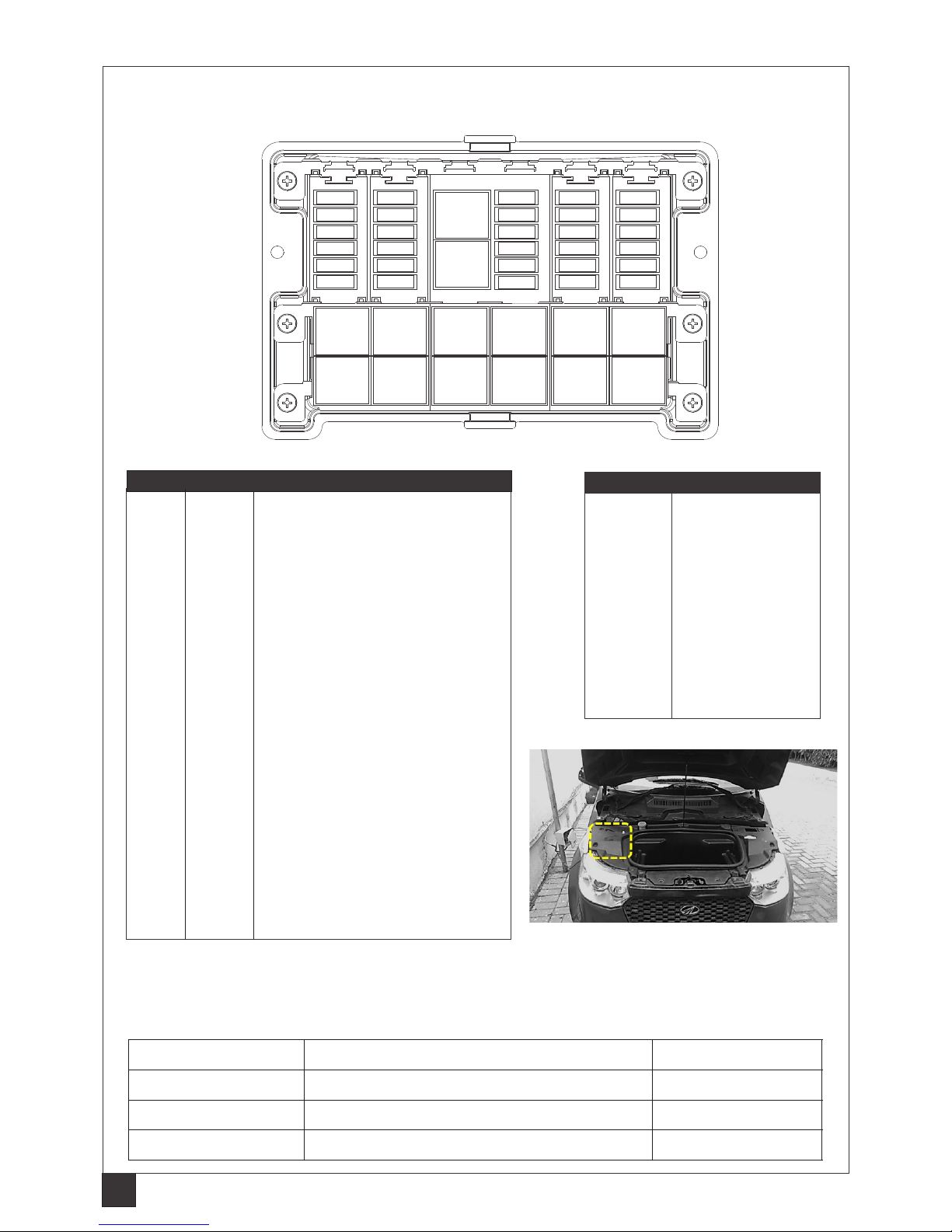
11.0 FUSE BOX DETAILS
Fluid leaks:
Check for leaks from battery and take appropriate measures to prevent personal injuries. Other fluids like wind
shield washer fluid, brake fluid & AC gas are same as in conventional cars that are to be dealt in same way.
14
RELAY CN 188
FR.FOG LAMP
RELAY CN 185
PARK LAMP
RELAY CN 186
REMOTE
BLOWER
RELAY CN 184
A/C HEATER
RELAY CN 182
HI BEAM
RELAY CN 187
CONDENSOR
RELAY CN 166
KEY RELAY
DRIVER
DUMMY
RELAY CN 183
LOW BEAM
RELAY CN 192
LATCH
RELAY CN 199
WIPER
(Hood open-
Wiper off)
RELAY CN 155
WASHER
MOTOR REAR
RELAY CN 169
IGNITION-2
RELAY CN 168
IGNITION-1
F1 F7
F8
F9
F10
F11
F12F6
F5
F4
F3
F2
F13
F14
F15
F16
F17
F18
F19
F20
F21
F22
F23
F24
F25
F26
F27
F28
F29
F30
Fuse box
F1 15A Head lamp low beam LH & RH
F2 3A Relay H/L low & high beam, position lamp
F3 20A Brake lamp, hazard, side indicator & HMSL
F4 5A Horn
F5 15A Front & rear wiper
F6 15A LH & RH door lock & rear hatch release
F7 15A Head lamp high beam LH & RH
F8 5A Position, roof, license lamps & back illumination
F9 5A Remote blower, A/C heater relay, cooling fan coil
F10 5A Rear washer motor
F11 10A Relay coil, BLDC condenser fan
F12 15A Blower fan & speed regulator module (SRM)
F13 30A Power window motor LH & RH
F14 20A Electric vacuum pump (EVP)
F15 15A Rear hatch defroster
F16 7.5A Front fog lamp-DRL
F17 3A Relay -key ON/OFF (ignition)
F18 3A OVRM, H/L adjuster LH & RH, switch
F19 3A Instrument cluster
F20 10A Infotainment system
F21 3A HVAC module(hatch & hazard) & IP cluster
F22 5A Anti-lock brake system (ABS)
F23 3A Air-bag
F24 3A Seat belt reminder (SBR)
F25 3A Ignition I/P to BCM & IEMS
F26 7.5A Aux 12V socket
F27 3A Ignition I/P to KSI SSR
F28 10A Tree switch- wiper & washer supply
F29 3A IGN I/P to HVAC, infotainment & OBD
F30 10A PRNDL, reverse lamp, camera & motor fan
Fuse no Rating (A) Circuit protected
Relay no Relay name
CN166 Key relay driver
CN168 Key relay 1
CN169 Key relay 2
CN182 Head light low beam
CN183 Head light high beam
CN184 Air condition-heater
CN185 Park lamp
CN186 Remote blower
CN187 Condenser fan
CN188 Front fog lamp
CN192 Latch
CN199 Wiper
Fuse box location
TYPE MATERIAL QUANTITY
A/C HFO- 1234YF (tetrafluropropane) 475±5grams
Brake fluid DOT-3 (Glycol Ether) 400 ML
Transmission oil Klubersynth GE475W90APIGL5 600 ML
12.0 LUBRICANTS CHART
Page 17
15
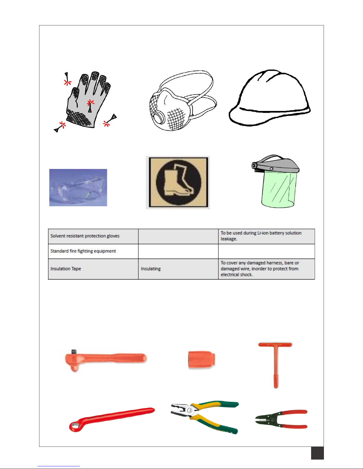
13.0 PERSONAL PROTECTIVE EQUIPMENTS AND INSULATED TOOLS
Always while performing any inspection, wear appropriate personal protective equipments before accessing
and working on car. Do not use damaged equipments at all instances to prevent personal injury. Always inspect
personal protective equipments periodically for deterioration and damages before use.
INSULATED TOOLS:
Always while performing any inspection, check or accessing electrical components in car, do use appropriate
insulated tools and equipments. Usage of these will prevent shock, personal injury ensuring safety during working
on car.
Insulated gloves (1000V)
Mask
Head gear
Goggles
Safety shield
Safety shoes
Page 18

UNLOCK
(anti-clockwise)
UNLOCK
14.0 ACCESSING OCCUPANTS AND RESCUE (Emergency response)
Hatch
release
Door unlock
DOOR LOCK:
TO UNLOCK MANUALLY:
To unlock the vehicle manually
in the event of central locking
inoperative, turn the key in anticlockwise direction respectively
as shown in the figure.
To unlock from inside, push door
lock lever backward as indicated
in the figure.
CENTRAL DOOR LOCK
TO UNLOCK :
To unlock using key fob, press the ‘Door unlock’ button once and both
the doors gets unlocked. In the event of not unlocking and central door
locking is inoperative, use general tools to open the doors and in
emergency cut open the doors at the hinges or at the door latch catcher.
II. Use the key fob to open the rear hatch by pressing the hatch release
button on the key fob once. The hatch gets released, if the key fob is not
working use the hatch release button on the climate control to release
the hatch.
DOOR LOCK
TO OPEN:
To open the doors, pull the door handle towards you to
unlock the door latch. And from inside use the door inner
handle to open by pulling it gently towards you as
indicated in the figure.
HAZARD WARNING:
Press the switch to activate the hazard warning lights.
All six external turn signal indicators will flash
simultaneously. To turn off the lights, press the switch
once again. This should be used to warn the traffic in the
event of any emergency.
1
2
3
PARKING BRAKE OPERATION
To Engage brake:
(1) Pull parking brake lever upwards.
To Disengage:
Press the button (2) on the lever and release the handle (3)
with a slight downward push while holding the release button
pressed. Make sure the handle has gone down fully for
complete release of parking brake prior to driving the vehicle.
The car has been equipped with
factory fitted central door
locking (CDL) system. Hence the
keys must be used to lock/
unlock the doors only when the
CDL system is not functional. It
is advisable to operate the
remote while the car is within
range.
Note
16
Page 19

17
REAR SEAT LOCK LATCH
IN EMERGENCY:
1. Remove the window glass if not lowered.
2. Open the doors.
3. Adjust the front seats for easy access by sliding and reclining as shown below.
PRESS
I. TO ACCESS THE FRONT SEAT FROM REAR
For accessing & adjusting the front seating position in the event
of evacuation either the recliner lever or tab can be used. To
adjust pull them and seat will slide and recline forward, release
the lever for locking.
II. RECLINING THE REAR SEAT REST
To adjust and fold the rear back rest to access from rear hatch,
release the rear seat rest latch by pulling both side tabs upwards
simultaneously and pushing the rest forward.
III. SEAT BELT
The seat belts are supplement restraint systems and to
release / remove the seta belts press the catcher downwards
as shown in the figure. The seat belt gets disengaged to access
and if seat belt cannot be unfastened, cut the belt in the event
of any emergency.
Recliner lever
Page 20
15.0 PROCESS FOR SHUTTING DOWN HIGH VOLTAGE SYSTEM
For shutting down the high voltage systems in the vehicle, first evaluate the extent of damage. Turning off
the key switch, isolate battery positive, insulating it will cuts off power supply to other components and
systems.
If the vehicle is damaged heavily, like battery pack damage / deformed, broken, use appropriate PPE’s
for battery handling.
Guidelines:
a) Always ensure to wear appropriate PPE’s during accessing the vehicle.
b) If the charge cable is connected to the vehicle, remove the same by refering the charge cable
disconnecting procedure (ii) in page .
c) Check for ‘key switch’ being ‘off ’
d) Check for ‘HVAC’ if the remote air conditioning is operational and disable it.
Note: The remote air conditioning system is a feature that can be enabled by the user via telematics by
a ‘personal computer’ or ‘Mobile App’.
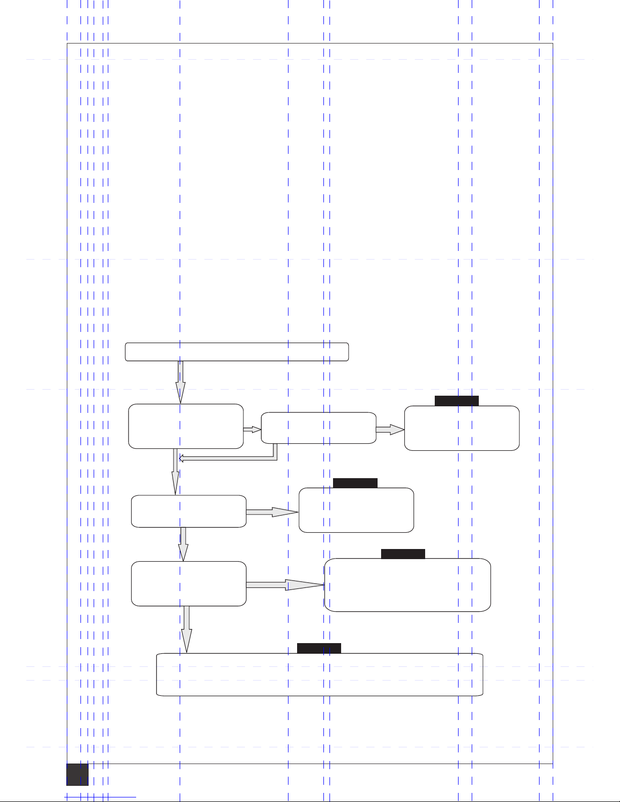
Flow chart for easy understanding & shutting down the vehicle high voltage supply.
Evaluate level of damage in the vehicle
Is vehicle have any
damage? (72V system
damaged / cuts / cracks)
Is the hood is operational
& Open the hood
Is vehicle rear tub can be
accessed & are insulated
tools / PPE’s available?
Is vehicle 72V system
is active?
Remove the key relays
from the fuse box.
Check fuse box layout
Open & access the rear tub
electronics and isolate 72 volts
system by disconnecting battery
positive and insulating it
Turn off the key switch.
Follow the procedure as
in the next page
In the event of not able to isolate the high voltage system, use appropriate
‘personal protective equipment’ and perform the rescue actions.
Yes
No
No
No
No
Yes
Yes
Yes
In the event of not able to do 1,2 & 3 then do the step 4
STEP 1
STEP 2
STEP 3
STEP 4
18
Page 21

19
16.0 HANDLING DAMAGED CAR AT ACCIDENT LOCATION
Always the car should be approached with caution while inspecting for level of damage. Evaluate for ectent of
damage (location and severity of damage, airbag deplyment etc.). The high voltage should be accessed with
appropriate presonal protective equipments with proper identification of components as per illustration in
given in page. Different situations are explained under for accessing occupants in case of any hazard.
i. High impact with high voltage system intact and occupants can be accessed without extrication tools:
Open the doors with manual key from key fob or open emergency rear hatch release to get the occupants
out of the car with emergency 72V system shutdown. The occupants assistance to begin immediately
without any waiting period.
ii. High impact with high voltage system intact and occupants cannot be accessed without extrication tools:
Wear appropriate personal protective equipments, use necessary tools to cut through the door mounting
hinge locations (in the event of rear hatch not opening and central door lock failure / jammed) to remove
door from car and extricate the occupants. Use emergency disconnect switch to isolate 72V system.
Hinge location
iii. High impact with high voltage system damaged:
Evaluate the extent of damage and if there is any evidence of damage to high voltage battery pack or
system ( arcing / sparking or orange colour high voltage cables damage, battery electrolyte smell). Do take
extreme care as there may be still risk of high voltage exposure. The car has to be accessed with extreme
caution to initiate high voltage system isolation and rendering assistance in occupants extrication. In the
event of limited access to deactivate the high voltage system, do wear appropriate personal protective
equipments, use necessary tools, follow appropriate risk management to prevent shock or electrocution
and extricate the occupants.
Page 22

20
Follow the airbag supplementary restraint system (SRS) deployment procedure before accessing
and dismantling process. This procedure is applicable for driver airbag (DAB), passenger airbag
(PAB) and seat belt pre-tensioners (front left and right).
1. Safety Precautions for removal or deployment of airbags eliminates the potential for hazardous
reactions during processing.
2. Follow the below precautions while disassembling the airbag SRS components or the wiring
point of those components.
• Be cautious while handling the ECU that activates the airbags and pretensioners.
• Do not carry the airbag module and seatbelt pretensioners by wires attached to inflators or other gas
generating devices.
• While handling the airbag, make sure the trims/covers (through which the airbag deploys) point away
from self or other persons and seatbelts shall not be handled on the webbing.
• If testing or deployment is required, make sure there is sufficient space around the airbag module so as
to allow the bag to inflate freely.
• Never place your head or body close to the front of an un-deployed airbag while dismantling.
• Do not drop the ECU while it is connected to airbag modules.
• Do not reuse the airbag, its ECU or any of its components that have been removed from a vehicle.
• An airbag that has been removed from a vehicle should never be installed in any other vehicle.
• Make sure the airbag is deployed fully, as the live airbag initiator can potentially discharge even after it is
separated from the airbag assembly, thereby causing serious injury or damage of equipment.
• Only trained personnel must remove the airbag inflator or pre-tensioner gas generator from the airbag
assembly.
• Wear appropriate protection, including eye and ear protection, during air bag deployment.
• Do not dispose of an undeployed airbag/pre-tensioners through normal disposal channels until it has
been fully deployed.
WARNING
AIRBAG AND COMPONENTS
17.0 AIRBAG ACCESS, DEPLOYMENT AND DISMANTLING (emergency response)
Page 23

21
Deployment of Airbags/Pre-tensioners
The airbag and pretensioner deployment shall be conducted only by trained personnel.
Recommended Procedure for Deployment of Airbags/Pre-tensioners within the Vehicle:
Note:
• The airbags must be deployed completely prior to emergency access (if required) and disposal.
• When deploying the airbag module or seat belt pre-tensioner, ensure that the vehicle is empty.
• Make sure that a battery is available to use as the power source to deploy the airbag.
1. After performing the “Preparation for Dismantling” procedure, disconnect the body wiring harness from
airbag modules, such as airbag ECU (under dead pedal on firewall), passenger airbag (PAB) (part of
instrument panel), driver airbag (DAB)(steering wheel horn pad) and seat belt pre-tensioners (below
rear quarter trim).
2. Wait for at least 60 seconds until the energy-reserve capacitor (part of ECU) gets discharged.
3. Make a jumper-wiring harness using two wires of 2 meters or longer. Connect the two leads together at
one end of the harness to avoid accidental deployment.
4. Cut the wires leading to the airbags and pre-tensioners. Allow at least 4 inches of wires to splice into the
jumper.
5. Connect the ends of the jumper-wiring harness to the ends of the wires leading to the airbag module
and seatbelt pre-tensioners. Cover the two wire leads using tape or other insulating material to prevent
the leads from contacting each other.
6. Make sure that all airbag modules and seatbelt pre-tensioners are properly mounted and secured in the
vehicle. Reinstall the DAB (part of steering wheel hornpad) and PAB on the vehicle with a tightening
torque of 10 Nm. Install the seat belt pre-tensioner with a tightening torque of 50 Nm.
7. Clear all loose items to ensure safe deployment procedure (for e.g., clear the front seat for DAB
deployment).
8. Notify all the people in the area about the airbag deployment and make sure that they are at least 30
feet away from the vehicle.
9. Separate the leads of the wiring harness and touch the leads on the terminals of a 12 V automotive
battery. Once the contact is made, airbag/pre-tensioner deployment will occur.
10. Leave the fully deployed airbag(s) in the vehicle, or remove for separate recycling.
11. The airbag modules are hot after deployment. Allow the airbags to cool for approximately 30 minutes
and the dust to settle before approaching the vehicle.
Always work from the side of DAB module or from the side or under of the front PAB module.
• Activate only one airbag module or seat belt pre-tensioner at a time.
• Keep water and other liquids away from the airbags.
• Never apply water to a deployed airbag module or seat belt pre-tensioner.
• Be sure to wear gloves when handling the deployed airbag module or seat belt pre-tensioner.
• Eventhough there is no poisonous gas produced upon the airbag deployment, be careful not to inhale
gas since it irritates the throat and can cause choking.
• Do not disassemble components of airbag module and seat belt pre-tensioner.
• Do not resuse the airbag module, seat belt pre-tensioner and ECU under any circumstances.
• If powder from the airbag contacts the skin, wash immediately with water.
WARNING
Page 24

22
BREAKDOWN VEHICLE RECOVERY (TOWING)
RECOMMENDED VEHICLE RECOVERY PROCEDURE IN THE EVENT OF BREAKDOWN
In emergency for breakdown of the vehicle, it is advised to follow the below types and adopt suitable one
to recover vehicle to the nearest service center. Normally break down vehicle can be recovered by below
3 types that are illustrated and explained that are safe. The second and third methods should be adopted if
a flat bed type is not available.
1. Flat bed: The break down vehicle is loaded on to back of the recovery truck. This is the safest and best
way of vehicle recovery.
2. Wheel lift: The tow truck pivot arms go below the tires of front and lift them off the ground. While the
other two wheels are on the ground. Ensure that key switch is off and hand brake released
prior to towing the vehicle with this option.
Note
! The third option should be used in the event of non availability of the above two options for recovering the
breakdown vehicle.
! Should follow and adhere to the given procedures while towing the breakdown vehicle.
3. Towing: This type of recovering the breakdown vehicle is by ‘Towing’ the broken vehicle. This requires a
set of simple steps to be performed prior to towing the breakdown vehicle as below.
1. Use towing cable and connect the breakdown vehicle to the recovery vehicle
2. Turn off the Key switch (SSB)
3. Switch on the Hazard warning
4. Release the hand brake
5. Caution & advise the maneuvering person of the breakdown vehicle
18.0 ROADSIDE ASSISTANCE
Remove toe-hook and mount it by rotating clockwise for towing as shown above
2. Wheel lift type - from front
Tow hook mounting point
Towing hook
1. Flat bed towing
Page 25

23
3. Towing by cable: The break down vehicle is fixed with a tow hook and using a towing cable, it is towed by
another vehicle.
START
Step 2
2
3
Step 3
For unexpected breakdown of the vehicle, push the car towards one side of the road. Organize for the
recovery vehicle and if not available, arrange for towing vehicle. Take the tow hook available in the tool kit. Tow
hook mounting threaded holes are provided at front LH side ends of the chassis frame near the bottom grill
below number plate. Fix the hook by turning it in the holes in anticlockwise. Tie one end of the towing rope to
the tow hook eye and the other to the vehicle towing the break down vehicle. While towing, key should be in
off position, hand brake in released condition and towing speed limited to less than 12 mph . This requires
another person for handling the break down vehicle.
! Always switch on hazard of both vehicles to caution other users of road
while towing breakdown vehicle.
! Do not tow the break down vehicle at more than 12 mph speed.
! Always maintain a gap of 4 meters between breakdown & towing vehicle.
! Always tow the vehicle without jerks to avoid snapping of the towing eyelet.
CAUTION
For road accident incidents:
Check if the vehicle is drivable, if so drive
off to road side, apply hand brake and turn
off start stop button.
CAUTION
Turn off ‘Start / Stop Button’ (SSB)
Release ‘Parking Brake’
Towing by cable (Maximum speed 12miles/hr)
Press parking brake release button 2 and
then push the parking brake lever 1 to
completely down position.
Mahindra e o cover- Road side assistance for breakdown and accidents:
2
If your vehicle breaks down or is involved in a crash, our service provider will recover your vehicle and all its
passengers within the legal carrying capacity of the vehicle to the Mahindra authorised service centre
workshop at Hayes Middlesex, or to a local workshop nominated by Mahindra or its authorised service
partner. If the breakdown occurs outside of Mahindra authorised service centre opening hours or if our
service provider cannot deliver the vehicle within Mahindra authorised service centre opening hours, our
service provider will provide recovery to your home address. You can call to arrange for vehicle recovery
during the Mahindra authorised service centre or service partner opening hours in the next working day.
Mahindra authorised service centre opening hours are Monday to Saturday 08.00 to 18.00 (GMT)
Once the vehicle has been taken to a Mahindra authorised workshop, it is then owners responsibility to
instruct the repairer to make any repairs required. The coverage applies for breakdowns occurring in Great
Britain only.
Recovery information:
a) Breakdown recovery from ETA national recovery
b) Coverage is with car sale for first year
c) Breakdown recovery covered in Great Britain only
d) Unlimited coverage plan
Mahindra e o cover toll free no: 08000 737 283
2
Page 26

24
Step 1: Use wheel spanner from tool kit purchased to remove the wheel.
A
B
Step 3: Place the jack, align the jack to jack mounting location beneath the car.
Step 4: If required remove the hubcap by holding the cap
on the top and tapping it gently. Loosen the fourwheel nuts, ½ turn with wheel spanner. Locate
the jack point nearest to the flat tyre you need to
change.
19.0 CHANGING A FLAT TYRE
The car can roll of the jack and seriously
injuring anyone underneath. Follow the
directions for changing a tyre exactly and
never get under the vehicle when only the
jack supports it.
CAUTION
Jack points
Step 2: Provide stopper to the wheel parallel to flat
tyre before Jacking up the vehicle for changing the
wheel.
The spare wheel, jack, jack handle, towing
hook and tool kit are car accessories that
does not come along with initial car
purchase. They are to be purchased by car
user for their use based on requirement.
Note
Page 27

25
Step 5: Once aligned to the jack point, turn the end bracket
clockwise until the top of the jack contacts the jack
point. Make sure the jack point tab is resting in the
jack notch. Use the jack rod to raise the vehicle
until the flat tyre is just off the ground.
Step 6: Remove the wheel nuts and flat tyre. Temporarily
place the flat tyre on the ground with the outside
surface of the wheel facing up. You could scratch the
wheel if you put it face down.
Step 7: Before mounting the spare tyre, wipe any dirt off the
mounting surface of the wheel and hub with a clean
cloth. Wipe the hub carefully, it may be hot from
driving. Put on the spare tyre. Put the wheel nuts
back on finger-tight, then tighten them in a
crisscross pattern with the wheel wrench until the
wheel is firm against the hub.
Step 8: Lower the car to the ground and remove the jack.
Tighten the wheel nuts securely in the same criscross pattern.
Tighten the wheel nuts to recommended torque (70Nm) and
re-fix the hubcap by placing it in its original position and
tapping it gently at center. Now the vehicle is ready to drive.
Page 28

26
Note:
DANGER:
HIGH VOLTAGE REPAIR IS
UNDER PROGRESS
DO NOT TOUCH
Sign: .........................................
DANGER:
HIGH VOLTAGE REPAIR IS
UNDER PROGRESS
DO NOT TOUCH
Sign: .........................................
FOLD HERE
Print this page and put it on the vehicle roof while carrying out the service
If the vehicle needs to be kept / stored unattended, ensure to put the below caution note on the breakdown
vehicle.
20.0 CAUTION NOTE
Page 29

Page 30

For Feed back and assistance contact:
Mahindra Reva Electric Vehicles Ltd.
Add: # 2, Road No 3, Bommasandra phase IV,
Industrial Area, Jigani Link Road, B’lore - 560099
e-mail: customercare@mahindrareva.com
 Loading...