

Page 1

OPERATOR'S MANUAL &
INSTALLATION INSTRUCTION
'ML170' Series
Click here to go on
INDEX
Main Menu
contactus@almats.com
Page 2
Includes: Operator’s Manual and Installation
Instructions
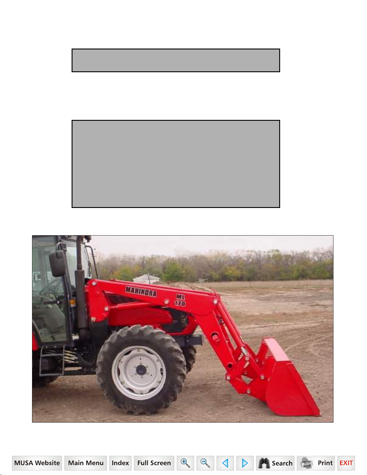
Mahindra USA
Model ML170
Front End Loader
1503-1066
Page 3

WARRANTY CONDITIONS
Warranty Coverage:
Mahindra USA, Inc., herein referred to as Mahindra, undertakes to replace or repair any part of a Mahindra loader
where damage has been proven to be caused by defects in material or workmanship.
This Warranty is valid for a period of 1 year for all hydraulic components and attachments and for a period of 2
years for all other loader components from the date of the original retail sale. Parts replaced or repaired under the
terms of this Warranty are guaranteed only until the original warranty expires.
It is further understood and agreed that the defect should be immediately reported to the Selling Dealer. The
Selling Dealer will generally perform Warranty repairs or replacements and the Purchaser shall deliver the
Mahindra Loader to the Dealer’s place of business for repair. In the event Purchaser is located more than 75
miles from the Selling Dealer, any Mahindra Dealer authorized to sell and service Mahindra Products may
perform the repair at its dealership.
The obligation of Mahindra to the Purchaser under this Warranty is limited to the repair or replacement of
defective parts by an authorized Mahindra dealer. Repair or replacement in accordance with this Warranty shall
constitute fulfillment of all liabilities of Mahindra and the Selling Dealer in respect to Mahindra Loaders.
There are no warranties beyond those which expressly appear herein. Any implied warranty of
merchantability or fitness for a particular purpose is specifically excluded here from.
Warranty Provisions:
Mahindra’s liability under this Warranty is subject to the observance by the Purchaser of the following provisions:
- The purchaser shall at all times in the operation of any Mahindra Product, use those brands and grades of
lubricating oils, lubricants or fuel and spare parts officially approved by Mahindra.
- The Mahindra Loaders shall have been used in accordance with the procedures specified in the Operator’s
Manual. This Warranty does not extend to damage resulting from misapplication, abuse, misuse, failure to
perform maintenance, negligence, fire, accidents or changes or faulty mounting carried out by the Purchaser.
When making a Warranty exchange of parts, the Purchaser shall compensate Mahindra for the time that the
parts have been used if they have been exposed to extreme wear.
- Compensation is not paid for physical harm, deadlock, resulting damages, or other losses.
- To obtain warranty service, the Purchaser must (1) report the product defect to an authorized Mahindra
dealer and request repair within the applicable warranty term and (2) present evidence of purchase or date of
original use.
- The Warranty shall be void if the Mahindra Loader has been altered or repaired outside of a Mahindra
dealership in a manner, which, in the sole judgment of Mahindra, affects its performance, stability, or
reliability.
- The customer shall be responsible for transportation expenses for the Mahindra Loader to the dealership or
travel of dealer personnel to customer location for Warranty repair. The customer shall also pay any premium
for overtime labor requested by the customer.
- Temporary repairs or additional costs due to the work being performed after normal working hours will not be
compensated.
- The above warranty is in lieu of all other warranties on Mahindra’s behalf and neither party assumes any
other liability in connection with Mahindra’s Products.
- Any dispute arising between Mahindra and the Purchaser concerning the liability of Mahindra under this
warranty shall be subject to the laws of the State of Texas.
Right To Make Design and Product Changes:
Mahindra reserves the right to make changes in the design and other changes in its Mahindra Products at any
time without incurring any obligation with respect to any product previously ordered, sold or shipped.
2
Page 4
CONGRATULATIONS
You are now the proud owner of a MAHINDRA ML170 Loader. This loader is a product of quality
engineering and manufacturing. It is made of fine materials and under a rigid quality control
system. It will give you long, satisfactory service. To obtain the best use of your loader, please
read this manual carefully. It will help you become familiar with the operation of the loader and
contains many helpful hints about loader maintenance. The immediate use of new techniques in
the manufacture of products may cause some small parts of this manual to be outdated.
Mahindra dealers will have the most up-to-date information. Please do not hesitate to consult with
them.
SAFETY ALERTS
This symbol, the industry’s "Safety Alert Symbol," is used throughout this manual and on labels to warn of the
possibility of personal injury. When you see this symbol, carefully read the messages and be alert to the
possibility of injury or death. It is essential you read these instructions and safety regulations before you attempt
to assemble or use this unit.
DANGER:
WARNING:
CAUTION:
IMPORTANT:
NOTE:
Indicates an imminently hazardous situation which, if not avoided, will result in death or
serious injury.
Indicates a potentially hazardous situation which, if not avoided, could result in death
or serious injury.
Indicates a potentially hazardous situation which, if not avoided, may result in minor or
moderate injury.
Indicates that equipment or property damage could result if instructions are not
followed.
Gives helpful information.
3
Page 5

SAFETY
Most tractor and/or loader equipment accidents can be avoided by following simple safety precautions.
The safety information given in this manual does not replace safety codes, insurance requirements, federal, state,
and local laws. Make sure your machine has the correct equipment required by your local laws and regulations.
Understand that your safety and the safety of other persons are measured by how you service and operate this
loader.
Know the position and operations of all controls before you try to operate. Make sure you check all controls in a
safe area before starting.
Read this manual completely and thoroughly and make sure you understand all controls. All equipment has a
limit. Make sure you are aware of the stability and load characteristics of this loader before you begin operation.
This safety alert symbol indicates important safety messages in this manual. When you see this
symbol, carefully read the message that follows and be alert to the possibility of personal injury or
death.
SAFETY PRECAUTIONS
READ MANUALS AND DECALS
1. Read and understand both the tractor and the loader Operator Manuals and all decals before using the
loader.
2. Lack of knowledge can lead to accidents.
3. It is the loader owner’s responsibility to make sure anyone operating the loader reads and understands this
manual first before operating the machine.
4. Follow all safety, operating, and service instructions.
5. Replace damaged or illegible safety labels. See following pages for required labels.
ROPS AND SEAT BELT
6. Equip your tractor with an approved rollover-protective structure (ROPS) or ROPS Cab and seat belt for your
protection.
7. ROPS (Roll-Over Protective Structures) and seat belt equipped tractors are recommended for operator use in
all loader operations.
8. Operator should wear safety hard hat, safety glasses, safety shoes, and other PPE. Avoid wearing loose
clothing or jewelry that may catch in moving parts.
9. Use seat belt as specified by tractor/ROPS manufacturer.
YOURSELF
10. Do not stand, walk, or work under a raised loader bucket or attachment unless it is securely blocked and held
in position.
11. Operate controls only when properly seated in the operator’s seat.
12. Only one person, the operator, should be on the machine when it is in operation.
13. Accidental movement of valve handle/handles or leak in the hydraulic system could cause the loader to drop,
or attachment to dump, causing severe injury.
OTHERS
14. Do not allow anyone in loader work area, under raised loader, or to reach through the loader boom when the
bucket or attachment is raised.
15. A frequent cause of personal injury or death is persons falling off and being run over. Inadvertent movement
of the loader or attachment could result in serious injury or death.
16. Do not permit others to ride on your tractor, loader, bucket, or any attachment.
17. Do not lift or carry anyone on buckets, forks, probes, or any other portion of the loader or loader attachments.
18. Do not allow children or unqualified persons to operate equipment.
4
Page 6

SAFETY PRECAUTIONS
PREPERATION
19. Move the wheels to the tractor manufacturer’s widest recommended settings to increase stability.
20. For better stability, always use a tractor equipped with a wide front axle, never use a tractor equipped with a
tricycle type front axle.
21. Add rear ballast or rear weight to the tractor to compensate for the load and increase stability.
22. Add recommended rear tire liquid weight or rear wheel weights for increased stability.
23. Do not modify, alter, or permit anyone else to modify or alter the loader, any of its components, or any loader
function without first consulting a Mahindra dealer.
24. Assemble, remove, and reinstall the loader only as directed in this manual. Failure to do this could result in
serious personal injury or death.
25. The loader may shift during shipping and handling, making it unstable on the pallet. Support loader with an
overhead hoist or other suitable means prior to removing bands or attaching straps securing loader to pallet.
Failure to do so could result in accidental tip-over of the loader that could cause serious injury to you and/or
bystanders.
BEFORE OPERATION
26. Before starting the engine of your tractor, make sure all operating controls are in park lock or neutral position.
27. Be certain lights and safety markings, as provided by the tractor manufacturer, are clean and operating when
transporting the tractor/loader on public roads. Be certain that the Slow Moving Vehicle (SMV) emblem is
visible. Check with local law enforcement for specific requirements.
OPERATION
28. Add wheel ballast and/or rear weight to counterbalance tractor/loader for stability at maximum loader capacity.
29. Additional counterweight requirements will vary with loader attachments and equipment application.
30. Move and turn the tractor at low speeds.
31. Carry loader boom at a low position during normal operation.
32. Never travel at high speeds with bucket loaded.
33. Use caution when operating the loader with a raised bucket or attachment.
34. Avoid driving over loose fill, rocks, holes, or anything that may be dangerous for loader operation or
movement.
35. Allow for the loader length when making turns.
36. Use caution when handling loose or unstable loads.
37. Gradually stop the loader boom when lowering or lifting loads.
38. When using remote hydraulic tractor valves on some tractors, the loader lift and dump cylinders will continue
moving unless the valve handle/handles are manually returned to neutral, or until relief pressure is reached at
the ends of piston strokes. Observe the bucket movement and maintain control with valve handle/handles.
39. Travel speed should be such that complete control and machine stability is maintained at all times. Where
possible, avoid operating near ditches, embankments, and holes. Reduce speed when turning, crossing
slopes, and on rough, slick or muddy surfaces.
40. A loader attachment should be transported in a low position at slow ground speeds. Make turns slowly and
use the tractor brakes cautiously. A loaded attachment in the raised position alters the center of gravity
location of the machine and increases the possibility of mishaps.
41. Be careful during loading, transporting, and stacking to minimize rolling bales and tractor tip over.
42. Do not use buckets, forks, or other attachments without bale retaining devices.
43. Operate the tractor and loader such that complete control and machine stability is maintained at all times.
44. When using a loader, be alert of bucket or attachment position at all times. Loader in raised position with
bucket or attachment rolled back can dump material onto tractor causing damage or injury to tractor and/or
operator.
LARGE HEAVY OBJECTS
45. Never use loader for handling large heavy objects, such as large round or rectangular bales, logs, and oil
drums unless loader is equipped with attachment that is designed to handle such objects.
46. Handling large heavy objects can be extremely dangerous due to danger of rolling the tractor over.
47. Handling large heavy objects can be extremely dangerous due to danger of upending the tractor.
48. Handling large heavy objects can be extremely dangerous due to danger of the object rolling or sliding down
the loader boom onto the operator.
5
Page 7

49. If you must handle large heavy objects, protect yourself by using caution, moving slowly, and avoiding bumps
and rough ground.
50. If you must handle large heavy objects, protect yourself by never lifting load higher than necessary to clear
the ground.
51. If you must handle large heavy objects, protect yourself by adding rear ballast to the tractor to compensate for
weight of load.
52. If you must handle large heavy objects, protect yourself by never lifting large heavy objects that may roll or fall
on the operator.
53. Never lift any load from any point of the loader with a chain, rope, or cable unless loader is equipped with a
Factory approved attachment that was designed and built for this type of lifting. Always follow lifting
instructions included with these attachments.
54. Use only Factory bale probe or bale retaining devise handler attachment when handling round bales.
55. Do not handle large square bales without a retaining device handler attachment.
56. Do not use buckets, forks, or other attachments without bale retaining devices.
57. Do not use loader for handling large, heavy objects such as logs, tanks, etc.
SAFETY PRECAUTIONS
SLOPES
58. Stay off of slopes too steep for safe operation.
59. Shift down before you start up or down a hill with a heavy load. Avoid "free wheeling."
60. Use extreme caution when operating on a slope.
61. Always operate up and down the slope, never across the slope.
ELECTRICAL
62. Avoid contact with overhead wires, power lines, and obstacles when loader bucket or attachment is raised.
63. Electrocution from power lines can occur with or without contact.
64. Check for underground utilities before digging below grade level.
65. Contact with overhead power lines can cause severe electrical burns or death from electrocution. Make sure
there is enough clearance between raised equipment and overhead power lines.
HYDRAULIC
66. Do not tamper with the relief valve setting. This will void warranty and could cause damage to loader and/or
tractor.
67. Escaping hydraulic fluid under pressure can have sufficient force to penetrate the skin, causing serious
personal injury. Do not use HANDS to search for suspected leaks. If injured by escaping fluid, obtain medical
treatment immediately.
68. Visually check for hydraulic leaks and broken, missing, or malfunctioning parts. Never use your hand to check
for suspected leaks under pressure. Use a piece of cardboard or wood for this purpose. Escaping hydraulic
fluid or diesel fuel leaking under pressure can have sufficient force to penetrate the skin and cause serious
infection or other personal injury. If injured by leaking fluid, seek medical attention immediately.
69. To prevent personal injury, relieve all pressure before disconnecting fluid lines.
70. Before applying hydraulic pressure, make sure all hydraulic connections are tight and components are in
good condition.
71. Be sure to purge all the air from the hydraulic system before attempting to raise or lower this machine.
72. When using remote hydraulic tractor valves on some tractors, the loader lift and dump cylinders will continue
moving unless the valve handle/handles are manually returned to neutral, or until relief pressure is reached at
the ends of piston strokes. Observe the bucket or attachment movement and maintain control with valve
handle/handles.
73. Raised loader or boom can fall due to hydraulic system failure.
74. To avoid serious injury or death: Block up or securely support loader and boom before working underneath.
75. To avoid serious injury or death: Purge all air from hydraulic system before attempting to raise or lower loader
or boom.
76. To avoid serious injury or death: Stand clear if lowering or raising loader or boom.
77. Do not use hand or skin to check for hydraulic leaks. Use cardboard or wood. Wear eye protection.
78. High pressure oil leaks can penetrate skin causing serious injury and gangrene. Consult a physician
immediately.
79. Lower the loader or boom and release hydraulic pressure before loosening fittings.
6
Page 8

SAFETY PRECAUTIONS
AFTER OPERATION
80. Before leaving the tractor seat, lower attachment or loader boom to ground, stop engine, lock parking brakes,
put all controls in neutral, relieve hydraulic pressure, and remove key before leaving operator's seat.
81. Before disconnecting hydraulic lines, relieve all hydraulic pressure.
82. Make sure all parked loaders on stands are on a hard level surface with all safety devices engaged to prevent
loader from falling and being damaged or injuring someone.
83. Always park loader with bucket attached to loader.
84. When a front loader is mounted on the tractor, enter and exit the operator’s seat only from left side of the
tractor.
85. Always park loader with a Factory attachment attached to the loader.
86. Special care should be taken to park or store attachments with points or sharp edges in a safe manner.
87. Make sure all parked loaders are on a hard level surface. Engage all safety devices to prevent loader from
falling and being damaged or injuring someone. Do not repair loader if it is not mounted on the tractor. Loss of
hydraulic fluid or removal of parts could cause loader to collapse resulting in injury.
REPAIR
88. Visually check for hydraulic leaks and broken, missing, or malfunctioning parts.
Make necessary repairs before operation.
89. To keep mounting kit hardware from loosening during loader operation, hardware must be torqued to
specifications noted in operator manual.
90. Always wear safety goggles when servicing or repairing the machine.
91. When servicing or replacing pins in cylinder ends, bucket, etc., always use a brass drift and hammer. Failure
to do so could result in injury from flying metal fragments.
92. Never tow from any point of the loader with a chain, rope, or cable. Doing so could cause a roll over or
serious damage to the loader.
7
Page 9

DANGER, WARNING, AND CAUTION
DECAL SAFETY MESSAGES
0595-3000 WARNING DECAL
1. Add recommended rear wheel ballast and/or rear counter-weight for stability.
2. Move wheels to widest recommended setting to increase stability.
3. Move and turn tractor at low speeds.
4. In transport carry the load low.
5. Lower loader to the ground when parked.
6. Before servicing or adjusting equipment:
* lower loader to the ground.
* shut off engine.
7. Relieve hydraulic pressure before disconnecting oil lines.
8. Observe safety recommendations in Loader Operations Manual.
0595-3001 WARNING DECAL
Crushing Hazard
9. Stay away from under lift arms and bucket!
10. Do not stand or work under a raised loader.
11. Support bucket and lift arms before working under loader.
12. Lower loader to the ground before leaving seat.
0595-3002 DANGER DECAL
13. Keep machine clear of overhead power lines to avoid death or serious injury.
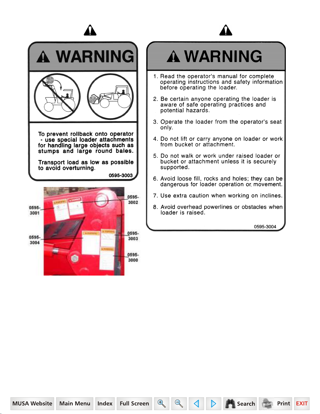
0595-3003 WARNING DECAL
14. To prevent rollback onto operator use special loader attachments for handling large objects such as stumps
and large round bales.
15. Transport load as low as possible to avoid overturning.
0595-3004 WARNING DECAL
16. Read the operator’s manual for complete operating instructions and safety information before operating the
loader.
17. Be certain anyone operating the loader is aware of safe operating practices and potential hazards.
18. Operate the loader from the operator’s seat only.
19. Do not lift or carry anyone on loader or work from bucket or attachment.
20. Do not walk or work under raised loader or bucket or attachment unless it is securely supported.
21. Avoid loose fill, rocks, and holes; they can be dangerous for loader operation or, movement.
22. Use extra caution when working on inclines.
23. Avoid overhead powerlines or obstacles when loader is raised.
8
Page 10

DANGER, WARNING, AND CAUTION
DECAL SAFETY MESSAGES
0595-2190 CAUTION DECAL
24. To prevent bodily injury and loader instability when detaching loader, equip loader with a material bucket.
0595-3050 DANGER DECAL
To avoid serious injury or death:
25. Unload only on a level surface.
26. Keep bystanders clear of work area when loading and unloading bales.
0595-3051 WARNING DECAL
27. Do not operate without confirmation that coupler pins are fully engaged.
28. Loader attachment can fall off if not properly attached.
To avoid serious injury or death:
29. Only use loader manufacturer approved attachments.
30. Read all operators manuals and decals before operating. Follow all safety operating and service instructions.
Contact dealer for replacement parts.
0595-3052 WARNING DECAL
To avoid serious injury or death:
31. Do not use pallet fork attachment to lift large objects, round bales, or items that may roll or slide down loader
arms onto the operator.
32. Never operate pallet fork without attaching plate guard.
33. Keep loads below pallet forks attaching plate guard heights.
34. Always transport loads with pallet forks low and level to ground.
35. Always keep pallet forks level when raising loads.
36. Avoid raising loads to full heights with pallet forks rolled back.
37. ROPS (Roll-Over Protective Structures) and seat belt equipped tractors are recommended for operator use in
all pallet fork operations.
38. Do not lift or carry anyone on buckets, forks, probes, or any other portion of the loader or loader attachments.
39. Do not allow riders on tractor, loader, or forks.
40. Avoid contact with electrical power lines by loader or attachments.
0595-3053 CAUTION DECAL
41. Maximum load limit on combined pair of forks is 5700 pounds.
0595-3054 CAUTION DECAL
To avoid serious injury or death:
42. Read operators manual and decals before operating.
43. Follow all safety operating, and service instructions. Contact dealer for replacement.
44. Be careful during loading transporting, and stacking to minimize rolling bales and tractor tip over. ROPS (RollOver Protective Structures) and seat belt equipped tractors are recommended for operator use in all bale
probe operations.
45. Do not allow riders on tractor loader or bale probe.
46. Avoid loading/unloading bales on sloping or uneven surfaces.
47. Avoid transporting with bales raised high. Keep bales tilted back and low to the surface while moving.
48. Approach, penetrate, and transport bales at low speeds. Reduce speeds on curves, hills rough ground, or
when turning.
49. Do not lift anything with bale probe except round bales.
50. Never raise round bale to full height with bale probe rolled back.
51. Park and store bale probe points pointed against bale, building, or other stable object.
9
Page 11

SAFETY DECALS
10
Page 12
SAFETY DECALS
Safety Decal Locations
Important: Safety decals 0595-3000, 0595-3001, 0595-3002,
0595-3003, and 0595-3004 are located on the loader LH
bearing box and are visible as you mount the tractor.
Care of Safety Decals
1. Keep safety decals clean and free of obstructing material.
2. Clean safety decals with soap and water and dry with a
soft cloth.
3. Replace damaged or missing safety decals with new
decals from your Mahindra Dealer.
4. If a component with a safety decal(s) affixed is replaced
with a new part, make sure new safety decal(s) are
attached in the same location(s) as the replaced
components.
5. Mount new safety decals by applying on a clean dry
surface and pressing air bubbles to outside edges.
11
Page 13

TABLE OF CONTENTS
1. Specifications...................................................14
1.1. Attachment Specifications.........................14
2. Introduction ......................................................15
3. Installation Instructions...................................16
3.1. Tractor Preparation...................................16
3.2. Mounting Kit Installation............................17
3.3. Hydraulic Installation.................................21
3.4. Loader Installation.....................................28
3.5. Connect Hydraulics...................................29
3.6. Bucket Level Indicator...............................30
Steering Stop...................................................30
4. Pre-Operation Instructions..............................31
4.1. Hydraulic Fluid..........................................31
4.2. Initial Loader Operation.............................31
4.3. External Loader Valve...............................31
4.4. Loader Mounted Valve Equipped With
Single Handle Controller On A Loader Not
Equipped With Hydraulic Self Level Option32
4.5. Neutral Position.........................................32
4.6. Neutral Lock Position................................32
4.7. Float Position............................................32
4.8. Regenerative Dumping Position ...............33
4.9. Initial Loader Operation.............................33
4.10. Removing Air From Hydraulic System....33
4.11. Relief Noise.............................................33
5. Daily Maintenance & Lubrication....................34
5.1. Daily Checks.............................................34
5.2. Loader Lubrication....................................34
Service Areas...................................................36
10. Pin On Bucket.................................................49
10.1. Installation Instructions To Pin On Quick
Attach .....................................................49
10.2. Installation Instructions Direct To Loader49
11. Pin On Bale Spear..........................................50
11.1. Pin On Bale Probe..................................51
11.2. Assembly Instructions.............................51
11.3. Installation Instructions To Pin On Quick
Attach .....................................................51
11.4. Installation Instructions Direct To Loader 51
11.5. Operating Instructions.............................51
12. Pin On Pallet Fork.......................................... 52
12.1. Pin On Pallet Fork...................................53
12.2. Assembly Instructions.............................53
12.3. Installation Instructions Pin On Quick
Attach .....................................................53
12.4. Installation Instructions Direct To Loader53
12.5. Operating Instructions.............................53
12.6. Parking Instructions................................53
12.7. Parking Stability......................................53
13. Optional Pin On Quick Attach System.........54
13.1. Recommended Loader Factory Approved
Attachments............................................54
13.2. Pin On Quick Attach ...............................54
14. Installing Bucket Or Attachment To Pin On
Quick Attach...................................................55
14.1. Recommended Loader Factory Approved
Attachments............................................55
14.2. Operating Instructions.............................55
6. Operating Instructions.....................................37
6.1. Filling The Bucket .....................................37
6.2. Lifting The Load........................................37
6.3. Carrying The Load....................................37
6.4. Dumping The Bucket ................................38
6.5. Lowering The Bucket................................38
6.6. Operating With Float Control ....................38
6.7. Loading From A Bank...............................38
6.8. Peeling And Scraping ...............................39
6.9. Loading Low Trucks Or Spreaders From A
Pile..........................................................39
6.10. Backfilling................................................39
6.11. Handling Large Heavy Objects ...............40
6.12. Back Grading..........................................40
7. Dismounting The Loader.................................41
8. Mounting The Loader.......................................45
9. Optional Grill Guard.........................................48
9.1. Installation Instructions .............................48
15. Removing Bucket Or Attachment From Pin
On Quick Attach.............................................58
15.1. Operating Instructions.............................58
16. Service And Lubrication For Pin On Quick
Attach..............................................................59
16.1. Keep These Areas Clean........................59
16.2. Lubricate Annually..................................59
17. Optional Skid Steer Tool Carrier System.....60
17.1. Recommended Loader Factory Approved
Attachments............................................60
17.2. Non-Loader Factory Attachments...........60
17.3. Skid Steer Tool Carrier System Service &
Lubrication..............................................61
18. Installation & Operation Of Skid Steer Tool
Carrier System...............................................62
18.1. Installation Instructions...........................62
18.2. Skid Steer Tool Carrier Handles In
Disengaged Position...............................62
18.3. Skid Steer Tool Carrier Handles In
Engaged Position ...................................63
12
Page 14

19. Installing Bucket Or Attachment To Skid
Steer Tool Carrier...........................................64
19.1. Operating Instructions.............................64
20. Removing Bucket Or Attachment From Skid
Steer Tool Carrier...........................................67
20.1. Operating Instructions.............................67
21. Skid Steer Bucket...........................................68
21.1. Skid Steer Bucket ...................................68
21.2. Installation Instructions To Skid Steer Tool
Carrier.....................................................68
22. Skid Steer Bale Spear....................................69
22.1. Skid Steer Bale Probe.............................70
22.2. Assembly Instructions.............................70
22.3. Installation Instructions To Skid Steer Tool
Carrier.....................................................70
NOTES:
22.4. Operating Instructions.............................70
23. Skid Steer Pallet Fork.................................... 71
23.1. Skid Steer Pallet Fork.............................72
23.2. Assembly Instructions.............................72
23.3. Installation Instructions To Skid Steer Tool
Carrier.....................................................72
23.4. Operating Instructions.............................72
23.5. Parking Instructions................................72
24. Trouble Shooting Procedures.......................73
24.1. Trouble Shooting For All Loaders...........73
24.2. Trouble Shooting For Loaders With
Optional Self Leveling.............................77
25. Torque Chart...................................................78
13
Page 15
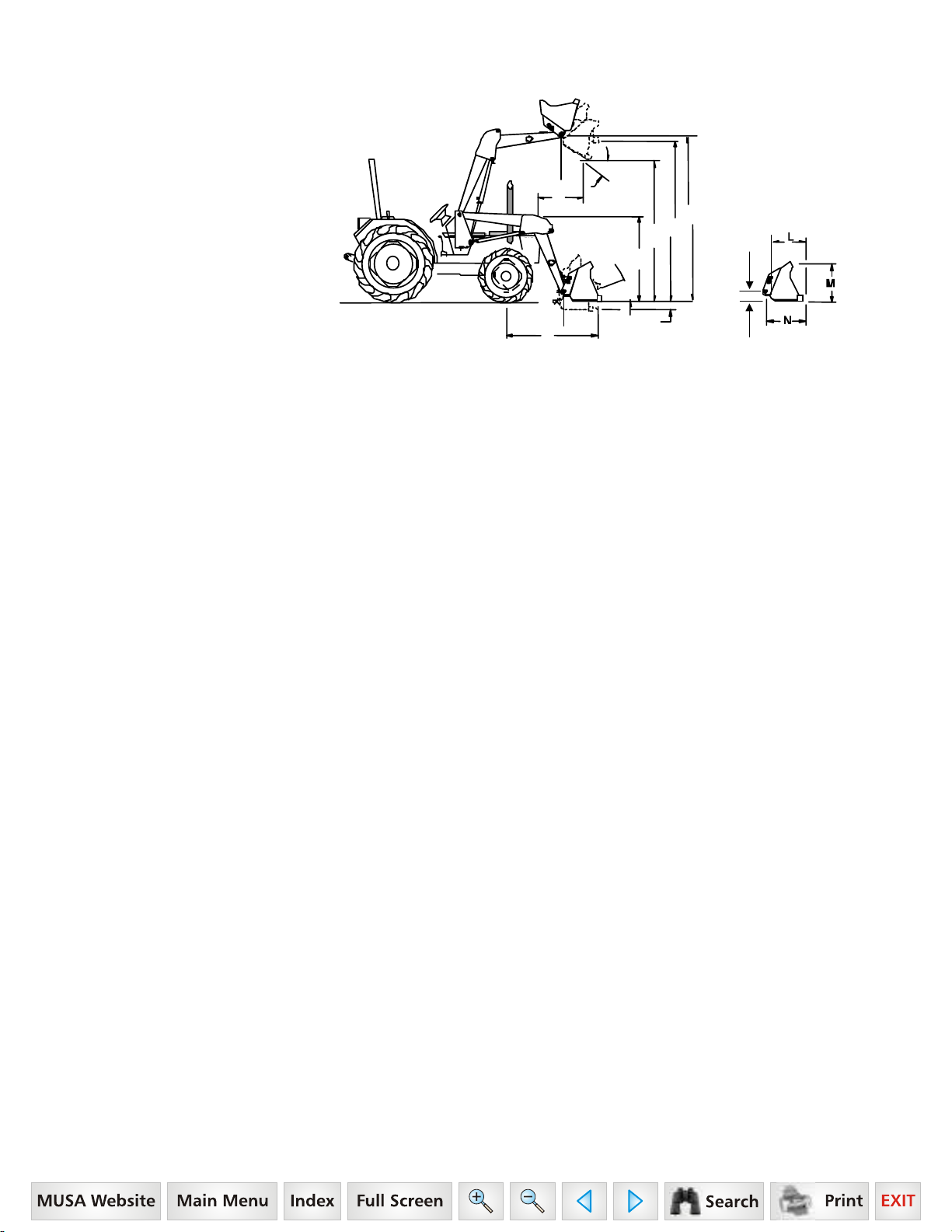
1. SPECIFICATIONS
Model ML170
Front End Loader
For Use With
Model 7010 Tractor
E
U
D
B
C
J
A
P
G
Y
F
H
SPECIFICATIONS OF LOADER:.....................................................................................................................ML170
A. Maximum Lift Height to Pivot Pin ................................................................................................11’ 0" (132")
B. Maximum Lift Height under Level Bucket...................................................................................10’ 3" (123")
C. Clearance with Bucket Fully Dumped...............................................................................8’ 6-1/2" (102.50")
D. Reach at Maximum Lift Height (to Grill Guard)...................................................................2’ 8-3/4" (32.75")
E. Maximum Dump Angle.................................................................................................................42 degrees
F. Reach With Bucket on Ground.......................................................................................................7' 2" (86")
G. Maximum Rollback Angle.............................................................................................................26 degrees
H. Digging Depth........................................................................................................................................6-1/4"
J. Overall Height in Carry Position .......................................................................................5’ 5-1/2"* (65.50"*)
L. Bucket Depth........................................................................................................................................25.86"
M. Bucket Height.......................................................................................................................................26.20"
N. Loader Bucket Pin to Front of Front Cutting Edge ...............................................................................33.46"
P. Loader Bucket Pin to Bottom of Front Cutting Edge ..............................................................................9.00"
U. Lift Capacity to Maximum Height at Pivot Pin ................................................................................... 3300 lb.
Y. Breakout Force at Ground Line at Pivot Pin...................................................................................... 5200 lb.
*Top of Arm at Bucket Pivot Pin with Bucket 12" off ground.
CYCLE TIMES 1000 RPM 1500 RPM 2000 RPM 2500 RPM
Raising Time Ground Line to Maximum Lift Height 16.5 sec........11.5 sec..........7.9 sec..........7.2 sec.
Lowering Time Maximum Lift Height to Ground Line 9.6 sec..........9.0 sec...........7.7 sec..........5.2 sec.
Dumping Time Full Rollback to Full Dump without Regen 10.0 sec.........7.8 sec...........5.4 sec.......... 4.5 sec.
Dumping Time Full Rollback to Full Dump with Regen 6.3 sec..........5.7 sec...........5.0 sec..........4.7 sec.
Rollback Time Full Dump to Full Rollback 7.0 sec..........5.6 sec...........3.5 sec..........3.1 sec.
Lift Cylinder Dia........................................................................................................................................................3"
Tilt Cylinder Dia..................................................................................................................................................2-1/2"
Tire Sizes (specifications taken with).................................................Front: 9.5Lx15.......................... Rear: 16.9x28
Relief Valve Setting (Loader Valve) w/o Hyd. Self Level............................................................................... 2600 psi
Relief Valve Setting (Loader Valve) with Hyd. Self Level .............................................................................. 2600 psi
Specifications taken with Mounting Kit, Hose Kit, and 78" Pin On Standard Bucket.
Specifications based on ASAE standards S301.3 and furnished for general information only as they can vary with different tractor
models. Specifications are subject to change without notice and without liability therefore.
1.1. ATTACHMENT SPECIFICATIONS
BUCKET STRUCK CAPACITY RATED SIZE CAPACITY
78" Pin On Material 18.59 cu. ft. 22.82 cu. ft.
14
Page 16
2. INTRODUCTION
This manual provides safety, installation, operation, maintenance,
removing, storing, and reinstalling instructions for your new midmount loader.
Your loader has been designed to give many years of satisfactory
service. Successful operation and long life of the loader depends, of
course, on proper operation and care. Please read this manual
carefully and follow the instructions. Correct operation and
maintenance will save much time and expense.
OBSERVE and follow all CAUTION, WARNING, and DANGER
instructions to help prevent personal injury and damage to the loader.
The reference to right hand (RH) and left hand (LH) used in this
manual refers to the position when standing at the rear of the unit
and facing forward.
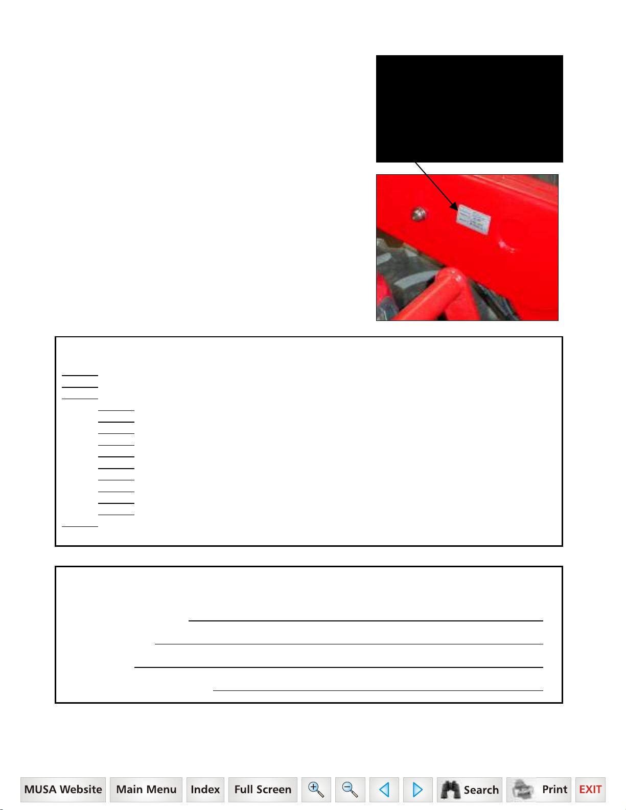
If, at any time, you have a service problem with your loader or need
new parts, contact your local Mahindra dealer. Your dealer will need
the loader model number and serial number to give you prompt,
efficient service. The serial number plate is located on the LH inside
front area of boom.
Before operating loader, check that your Dealer has covered the following information with you:
Equipment has been completely assembled as directed.
Equipment has been functionally tested for proper operation.
Purchaser has been instructed in proper & safe operating methods:
Operators Safety Precautions
Tractor Wheel Tread-Tire & Inflation Recommendations
Tractor Hydraulic System & Loader Controls
Rear Ballast Recommendations
Hydraulic System Oil Level
Proper Loader Operation
Loader Removal
Loader Installation
Lubrication - Service Care
Storage
Warranty Coverage & Operators Manual explained to purchaser.
Mahindra ML170 Loader Serial Number Information
LOADER SERIAL NUMBER
DATE PURCHASED
DEALER NAME
AND TELEPHONE NUMBER
15
Page 17
3. INSTALLATION INSTRUCTIONS
CAUTION: Equip your tractor with a ROPS cab or frame for your protection. See your
tractor/ROPS Operator Manual for correct seat belt usage.
Read entire instructions before beginning to install the loader. Personal injury and machine damage may be
prevented if you read and understand these instructions and special safety messages.
When you are in the tractor seat looking forward, the RH and LH sides of the tractor and loader are the same as
your right hand and left hand.
3.1. TRACTOR PREPARATION
3.1.1. Tractor Front Tires
Use front tires of equal size and maintain equal pressure in each tire. The pressure of the front tractor tires must
be increased to the maximum approved pressure recommended by the tire manufacturer to compensate for
additional load placed on the tires with the Front End Loader. See your tractor Operator Manual. Adjust the front
tires to the widest recommended setting on adjustable models for maximum stability. Front end weights must NOT
be used while loader is on the tractor.
3.1.2. Tractor Rear Tires
Maintain equal pressure in each of the rear tires. Use the widest recommended rear wheel setting for maximum
stability.
3.1.3. Tractor Ballast
CAUTION: To help prevent rollover, use recommended rear tractor ballast and widest wheel
settings to maximize stability. See your tractor Operator Manual for recommendations
Front tractor weights must only be used when the loader is parked. Weights must be removed before remounting
loader or serious damage will occur to loader or tractor front axle due to excessive weight.
The use of adequate rear counterweight to counterbalance for maximum loader capacity is required for safe
loader operation. Weight added to the rear of the tractor provides better traction and easier, more efficient loader
operation.
IMPORTANT: Do not exceed the maximum load capacity of the tires on your tractor. See Tire and Wheel
Specifications in tractor Operator Manual for more information.
3.1.4. Remove all loader components from shipping packaging.
WARNING: To avoid serious injury or death: Read before cutting bands or removing attaching
straps. The loader may shift during shipping and handling, making it unstable on the pallet.
Support loader with an overhead hoist or other suitable means prior to removing bands or
attaching straps securing loader to pallet. Failure to do so could result in accidental tip-over of
the loader that could cause serious injury to you and/or bystanders.
CAUTION: Lift and support all loader components safely.
16
Page 18
3.2. MOUNTING KIT INSTALLATION
3.2.1. Position the tractor and loader on a hard level surface under a hoist.
3.2.2. Remove front weights from tractor.
IMPORTANT: Do not tighten any hardware until all components are attached onto the tractor.
CAUTION: Lift and support all loader components safely.
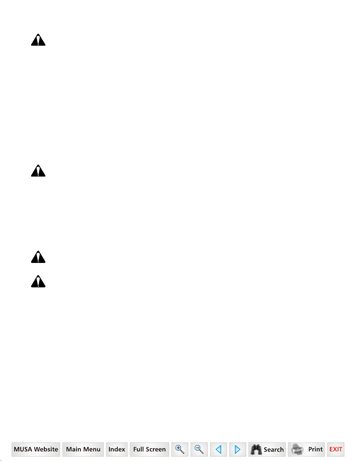
3.2.3. Check right hand side of tractor in front axle
area. Reposition components as shown so they will
clear loader bracket.
Reposition components
3.2.4. Position hoist with chain through center bracket
hole to support bracket during installation.
Position hoist with chain
through this hole when
mounting center bracket.
3.2.5. With hoist supporting center bracket, locate
oscillation stop with tab under and toward front of
tractor and 1/2" thick 4-hole spacer between center
bracket and tractor. Install 16mm x 2.0P x 90mm hex
bolts Grade 10.9, 5/8" lockwashers, and 5/8"
flatwashers, 4 places. Do not remove hoist.
Oscillation Stop
Spacer, 4-Hole
16mm x 2.0P x 90mm Grade 10.9 Hex Bolt,
5/8" Lockwasher, and 5/8" Flatwasher,
4 places.
Center Bracket
17
Page 19

3.2.6. With hoist supporting Center Bracket
center bracket, install
16mm x 2.0P x 30mm
Grade 8.8 hex bolts
and 5/8" lockwashers,
2 places inside and
2 places outside
of bracket in front
area of cab.
Do not remove hoist.
3.2.7. From rear axle, remove inside set of bolts and
lockwashers securing 3-point components to rear axle.
Save hardware.
Position of bolts to be removed
one on each side of axle.
16mm x 2.0P x 30mm Grade 8.8
Hex Bolt and 5/8" Lockwasher,
2 places inside (shown in illustration) and
2 places outside (shown in photo).
3.2.8. Install rear rail to center bracket using 5/8" x
1-3/4" hex bolts Grade 5, lockwashers, and hex nuts,
2 places outside only.
Center Bracket
5/8" x 1-3/4" Hex Bolt Grade 5,
5/8" Lockwasher, and 5/8" Hex Nut.
2 places outside only.
Rear Rail
18
Page 20

3.2.9. Install rear rail to rear axle as shown re-using
bolts and lockwashers just removed along with 1/2"
flatwashers included with mounting kit.
Position of bolts previously removed.
Tractor Bolt and Lockwasher along with
Mounting Kit 1/2" Flatwasher, 2 places each side
Rear Rail, 1 place each side
3.2.10. Remove hoist from center bracket.
3.2.11. Install opposite brackets using previous
instructions.
3.2.12. Install crossbrace to RH and LH center brackets
using 5/8" x 2" hex bolts Grade 5, lockwashers,
flatwashers, and hex nuts, 2 places Inside only.
RH Center Bracket
5/8" x 2" Hex Bolt Grade 5,
5/8" Lockwasher, and 5/8" Hex Nut,
2 places each side inside only
RH Rear Rail
Crossbrace
3.2.13.
5/8" x 1-3/4" hardware, securing rear rail to center
bracket is located in outside 2 holes.
5/8" x 2" hardware, securing crossbrace and rear rail to
center bracket is located in inside 2 holes.
NOTE: Do not tighten any of the crossbrace
hardware until all other mounting bracket hardware
is torqued to specifications.
CRITICAL: Torque all mounting kit hardware.
Reference Photo:
RH Rear Rail
Crossbrace
5/8" x 2" hardware,
inside 2 holes each side
LH Rear Rail
5/8" x 1-3/4" hardware,
outside 2 holes each side
19
Page 21
p
,
A. Identify hardware size and grade.
B. Refer to Torque Chart, page 78 and find correct torque for your hardware size and grade.
C. Torque hardware to this specification unless otherwise specified.
IMPORTANT NOTE: To keep mounting kit hardware from loosening during loader operation, hardware
must be torqued to specifications.
Center
Bracket RH
5/8" x 1-3/4" Hex Bolt, Lockwasher,
and Hex Nut, 2 places each side.
16mm x 2.0P x 30mm Hex Bolt Grade 8.8
and 5/8" Lockwasher, 4 places each side.
5/8" x 2" Hex Bolt, Lockwasher,
and Hex Nut
2 places each side.
5/8" x 2" Hex Bolt,
Lockwasher, and Hex Nut,
2 places each side.
Center Bracket LH
16mm x 2.0P x 30mm
Hex Bolt Grade 8.8
and 5/8" Lockwasher,
4 places each side.
5/8" x 1-3/4" Hex
Bolt, Lockwasher,
and Hex Nut
2 places each side.
Oscillation
Stop LH
1/2" 4-Hole
Spacer
16mm x 2.0P x 90mm Hex Bolt Grade 10.9,
5/8" Lockwasher, and 5/8" Hardened
Flatwasher, 4 places each side.
Oscillation
Stop RH
16mm x 2.0P x 90mm Hex Bolt Grade 10.9,
5/8" Lockwasher, and 5/8" Hardened
Flatwasher, 4 places each side.
Rear Rail RH
Crossmember
1/2" Hardened
Flatwasher plus
Tractor Hardware,
2
laces each side.
Rear Rail LH
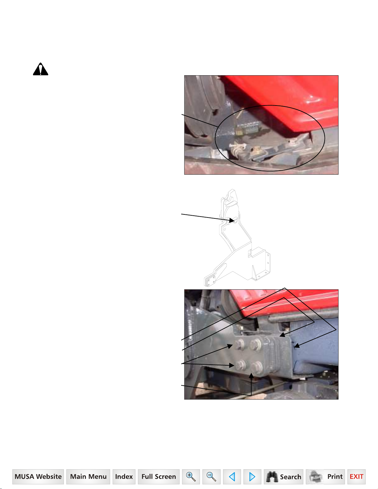
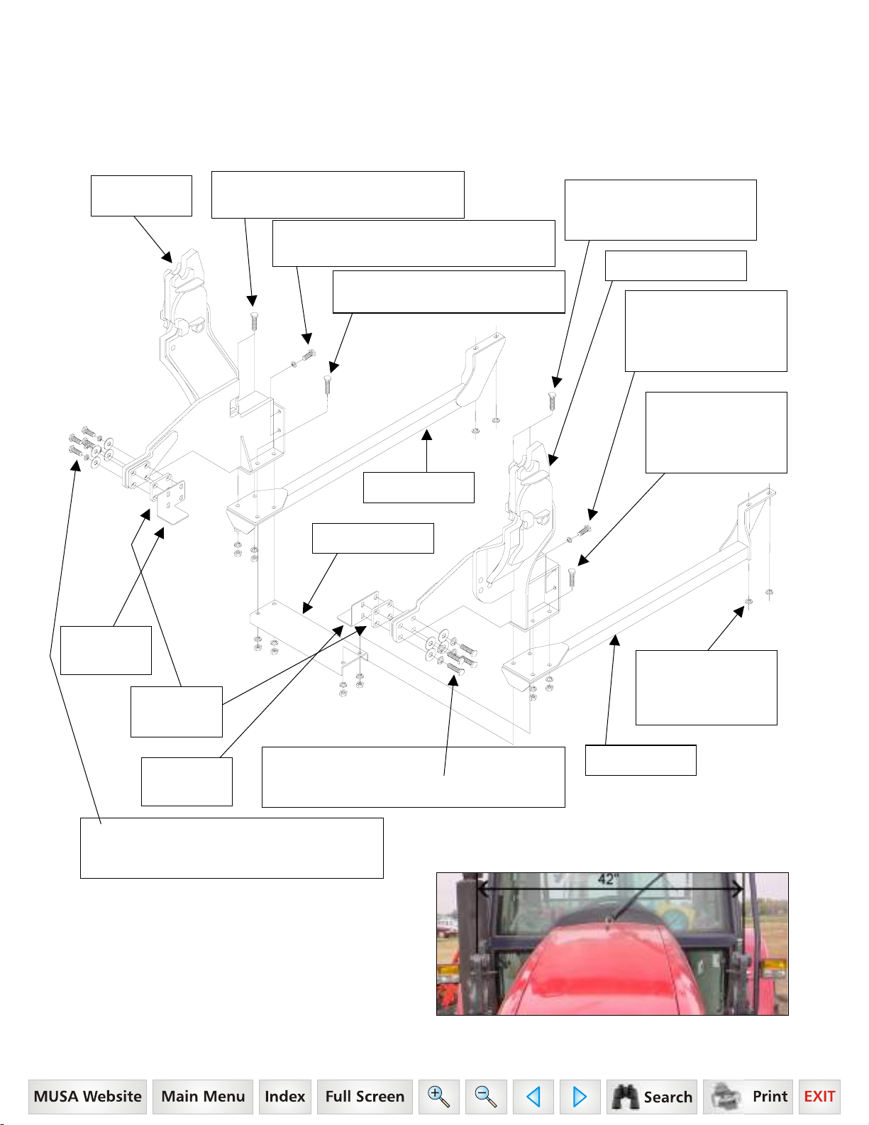
3.2.14. Verify outside surface of brackets are level and
the centerline measurement from RH to LH towers
reads 42" plus or minus 3/8".
20
Page 22
3.3. HYDRAULIC INSTALLATION
r
r
r
3.3.1. Remove RH cab console components to reveal
existing console bracket. Save console components
and console hardware.
RH Cab Wall
Existing Console Bracket
(installed on tractor).
3.3.2. Remove RH cab floor plate cover to reveal
opening to outside of cab. Save floor hardware.
Front of Tracto
Center
of Cab
Cab Floor Opening.
3.3.3. Peel rubber boot back from controller to
expose controller linkage. Position single lever
controller with cables so solid post is positioned
toward front and center of tractor.
Float part of decal faces toward front of tractor.
Rubber Boot, in raised position.
Lift Cable controls Raise & Lift
functions of Loader.
Solid post positioned toward
front and center of tractor.
Single Lever Controller.
8mm x 80mm Hex Bolt Grade 10.9 and
5/16" Lockwasher, 2 places.
Tilt Cable controls Dump & Rollback
functions of Attachment.
3.3.4. Install single lever controller to existing console
bracket using 8mm x 80mm hex bolts Grade 10.9
and 5/16" Lockwashers.
Existing Console Bracket
Front of Tracto
Center
of Cab
Front of Tracto
Center
of Cab
Two 5/16" spacer flatwashers
on top bolt only.
Single Level Controller
with pre-assembled Cables.
21
Page 23
IMPORTANT NOTE: Two flatwashers must be
r
r
used on top bolt between controller and console
bracket to tilt handle toward operator. Do not use
flatwashers on bottom bolt.
Two 5/16" spacer flatwashers
on top bolt only.
No Flatwashers on bottom bolt.
Existing Console Bracket
Single Level Controller
3.3.5. Route cables down through cab floor opening.
Install new triangle floorboard plates around cables
re-using floor hardware just removed.
Triangle Floorboard Plates.
Re-use floor hardware.
3.3.6. Apply silicone sealant around cables and
between triangle plates to reduce air and dust leaks.
Silicone sealant
must be supplied by installer.
3.3.7. Reposition rubber boot over single level
controller.
Rubber Boot repositioned.
3.3.8. Reinstall cab console components and secure
using console hardware.
Front of Tracto
Center
of Cab
Front of Tracto
Center
of Cab
Cab Console Components Reinstalled
3.3.9. Remove RH cab step. Save step and step
hardware.
RH Cab Step
22
Page 24
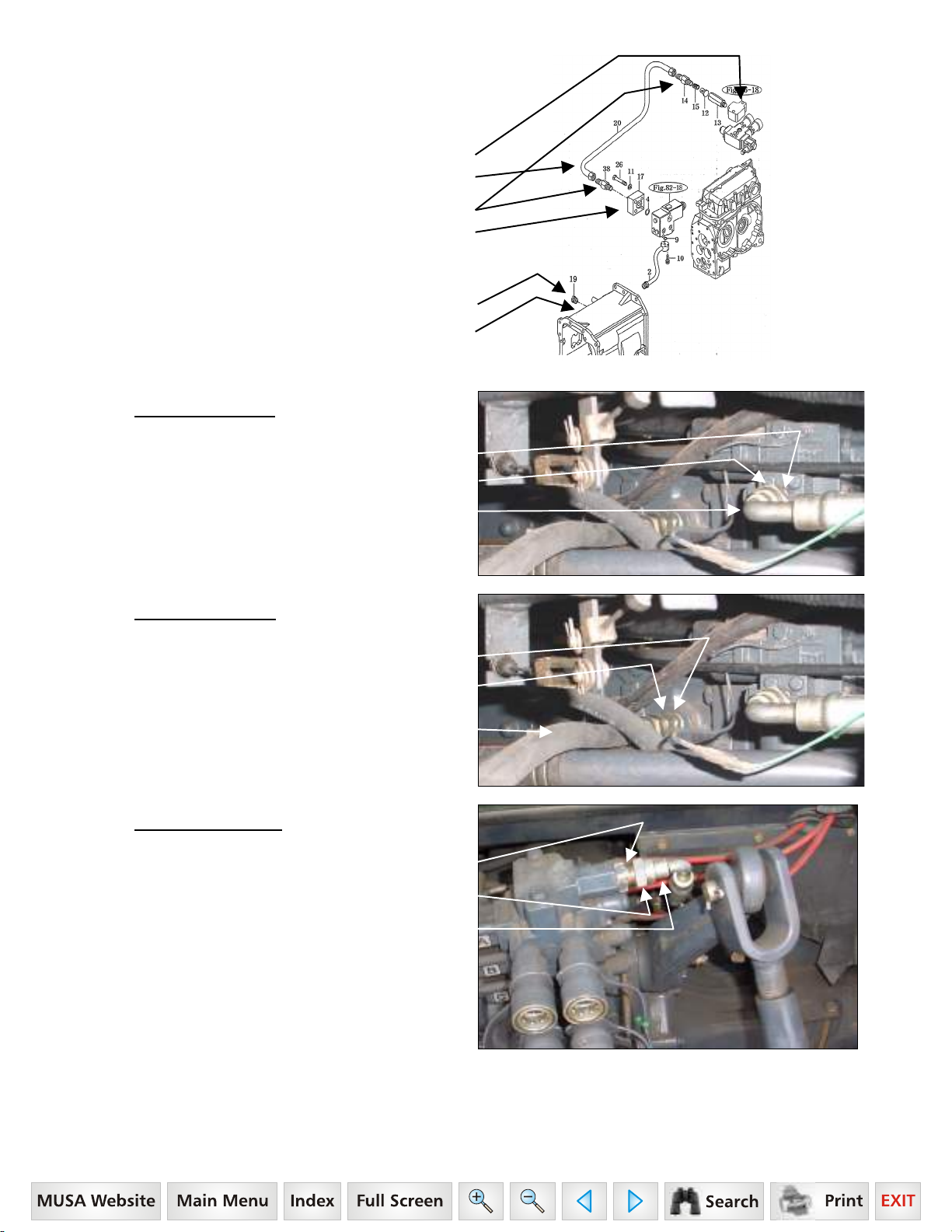
3.3.10. From RH side of tractor underneath cab,
remove hydraulic hose connecting tractor pressure port
to tractor power beyond port. Keep tractor fittings in
place.
Tractor Power Beyond Port Location.
Tractor Hose – Remove.
Tractor Fittings – Do Not Remove.
Tractor Pressure Port Location.
3.3.11. Remove plug from tractor transmission port.
Tractor Plug – Remove.
Tractor Transmission Port
3.3.12. Pressure "IN" Line:
Install 17" hose to tractor
straight fitting in tractor pressure port.
Tractor Pressure Port
Tractor Straight Fitting
Hose 1/2" x 17"
BSPP F 1/2" 90
3.3.13. Return "OUT" Line:
Install fitting and 25" hose
to tractor return port.
Tractor Return Port
Fitting Straight
BSPT F 1/2" x JIC M 7/8"
Hose 1/2" x 25"
JICF 7/8" X JICF 3/4" 90
3.3.14. Power Beyond Line:
Install 60" hose to tractor
straight fitting in tractor power beyond port.
o
x JICF 3/4"
o
Tractor Power Beyond Port
Tractor Straight Fitting
Hose 1/2" x 60"
BSPT M 1/2" 90
o
x JICF 3/4"
NOTE: Do not start tractor engine until these hoses are installed and secured to the loader valve.
23
Page 25

3.3.15. Loaders That Are Not Equipped With Hydraulic Self Leveling: Rotate loader valve so that Port "D" is
upward. Install orifice fitting by dropping it into Port "D" with slot of orifice facing upward. Screw fitting into Port "D"
to secure orifice into port. (Do not install orifice on Loaders equipped with Hydraulic Self Leveling.)
Port "D" in Loader Valve. Orifice (slot upward). Fitting Straight ORBM 3/4" x ORBM 3/4".
Port "D" in Loader Valve.
3.3.16. Install fittings to valve as follows:
(2) (1)
Power Beyond side of valve.
Port "C" Tilt Cylinder Base End
Yellow Tie
Port "D" Tilt Cylinder Rod End
Red Tie
Port "B" Lift Cylinder Rod End
Blue Tie
Port "A" Lift Cylinder Base End
Green Tie
NOTE: Do not tighten power beyond or pressure
hose until they are connected to tractor.
(3)
(1) Port "A", "B", "C", & "D":
Fitting Straight ORBM 3/4"
x ORBM 3/4".
(2) Port "D":
Install Male Quick Coupler,
Install
Power Beyond Port Return "OUT" Port
only into Port "D".
(3) Port "A", "B", & "C":
Install
Female Quick Coupler,
into remaining three ports.
(4) Power Beyond Port:
o
90
JICM 3/4" x ORBM 3/4".
Install Fitting
(6) Return "OUT" Port:
Install Fitting
Straight JICM 3/4" x ORBM 7/8".
(7) Pressure "OUT" Port:
o
90
JICM 3/4" x JICF 3/4".
Install Fitting
(8) Pressure "IN" Port:
Install Fitting
Straight JICM 3/4" x ORBM 7/8".
(9) Pressure "IN" Port:
o
90
JICM 3/4" x JICF 3/4".
Install Fitting
No Relief Plug installed at Factory
Pressure "IN" Port
Tilt
Spool
Lift
Spool
No Relief
Plug
installed
at Factory
(4)
(7)
(6)
(8)
(9)
24
Page 26

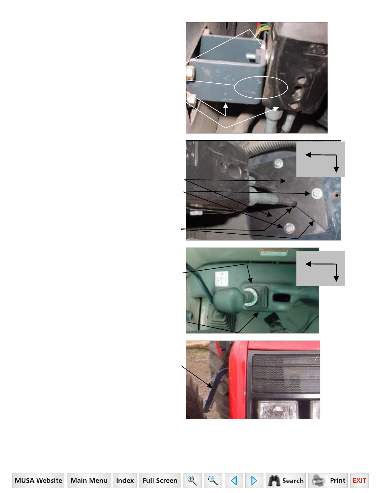
3.3.17. Install valve mount to tractor mount located
r
under RH side of cab behind cab step that was just
removed. Secure using 8mm x 20mm hex bolt and
5/16" lockwasher, 3 places.
Valve Mount
8mm x 1.25P x 20mm Hex Bolt
and 5/16" Lockwasher,
3 places.
Tractor Mount
Front of Tracto
3.3.18. Install valve to valve mount under RH side of
cab using 5/16" x 1" hex bolt and 5/16" lockwasher,
3 places.
Valve
5/16" x 1" Hex Bolt
and 5/16" Lockwasher,
3 places.
Valve Mount
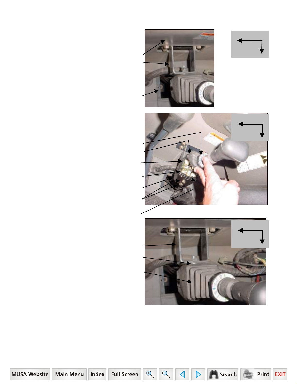
3.3.19. Identify and trace cables from Single Lever
Controller.
Raise and Lower (Lift) Cable is Frontward Cable
Dump and Rollback (Tilt) Cable is Rearward Cable
3.3.20. Install raise and lower (lift) cable to upper spool
of valve and dump and rollback (tilt) cable to lower
spool of valve as follows. Refer to photo and illustration
following.
Front of
Tractor
Center of Cab
25
Page 27

A. Thread large jam nuts entire length of threaded hubs
and onto cables.
B. Place dual flange over both cables.
C. Thread sleeves entire length of threaded hubs and
onto cables.
D. Thread small jam nuts onto cable threaded rods until
they bottom out on threads.
E. Place connectors onto threaded rods and against jam
nuts. Align connectors so they will mate with spool
terminal eyes and secure jam nuts against connectors.
F. Slide connectors onto spools and align the holes.
Insert pins through connectors and spool holes.
G. With cables attached to valve and single handle
controller, turn the sleeves onto threaded hubs until
they are flush with the valve face.
NOTE: When turning the sleeves, make sure the single
handle controller remains in the neutral position.
H. Tighten large nuts against sleeves to lock in position.
I. Slide dual flange into position and secure using socket
head cap screws and flatwashers.
NOTE: Over-tightening will distort flange.
Install Install
Dump and Rollback Raise and Lower
(Tilt) Cable to (Lift) Cable to
Lower Spool of Valve Upper Spool of Valve
NOTE: Controller handle can be repositioned slightly
by tightening or loosing sleeves.
Socket Head
Cap Screw and
Flatwasher
Cable
Threaded Hub
Dual Flange
Dual Flange Pin Connector Small Nut Sleeve Large Nut
Socket Head Cap Screw/Flatwasher Spool Terminal Eye Threaded Hub Cable
26
Page 28

Cable Adapter Group
Valve
Pressure
"IN" Port
Return
"OUT" Port
Single Lever
Controller
Solid Post – located
front and center of
Tractor
Triangle Floorboard
Plates
Raise and Lower
(Lift) Cable Frontward
Dump and Rollback
(Tilt) Cable Backward
Pressure "IN" Line
17" hose (opposite of
power beyond port)
Return "OUT" Line
25" hose
Return "OUT" Line
Fitting
Power Beyond Line
60" hose
3.3.21. Route 17" pressure hose to fittings in pressure
port of valve.
17" Pressure Hose
3.3.22. Route 25" return hose to fittings in return port of
valve.
25" Return Hose
3.3.23. Route 60" power beyond hose to fitting in power
beyond port of valve.
60" Power Beyond Hose
3.3.24. Remove all twists from hoses then tighten
hydraulic connections.
3.3.25. Check that all hydraulic connections have been
tightened.
3.3.26. Reinstall RH cab step reusing cab step
hardware.
Cab Step Hardware
Raise and Lower (Lift) Cable
Dump and Rollback (Tilt) Cable
RH Cab Step
27
Page 29

3.4. LOADER INSTALLATION
3.4.1. Remove all loader components from shipping package.
CAUTION: Lift and support all loader components safely.
IMPORTANT: Do not extend tilt cylinders without attachment pinned to loader. Failure to follow these
instructions could cause loader damage and void warranty.
3.4.2. Loader valve hoses and quick couplers have been pre-assembled on loader. Unwrap these hoses by
cutting nylon ties securing them to side of loader.
3.4.3. Before installing loader to tractor, use a hoist to install pin on
bucket or pin on attachment and bucket or skid steer attachment
and bucket on loader. Secure using pins and e-clips, 4 places.
Top Pin 1-1/8" x 7.01",
Grease Fitting 1/4"-28 and E-Clip,
1 place each side.
Bottom Pin 1-1/8" x 7.01",
Grease Fitting 1/4"-28 and E-Clip,
1 place each side.
Refer to Section 10 for Pin On Bucket, page 49.
Refer to Section 11 for Pin On Bale Spear, pages 50 to 51.
Refer to Section 12 for Pin On Pallet Fork, pages 52 to 53.
Refer to Sections 13 to 16 for Optional Pin On Quick Attach System, pages 54 to 59.
Refer to Sections 17 to 20 for Optional Skid Steer Tool Carrier System, pages 60 to 67.
3.4.4. Following these instructions will add stability to loader package and will allow easier handling of loader with
hoist.
3.4.5. Support the loader by using a hoist. Install loader to mounting brackets previously installed on tractor.
Refer to Section 8 — Mounting the Loader, pages 45 to 47.
CAUTION: Lift and support all loader components safely.
28
Page 30

3.5. CONNECT HYDRAULICS
3.5.1. Verify all working port hose connections.
(C) Connect Port "C" to Tilt Cylinder Base End
(D) Connect Port "D" to Tilt Cylinder Rod End
(B) Connect Port "B" to Lift Cylinder Rod End
(A) Connect Port "A" to Lift Cylinder Base End
(1) "PBY" Power Beyond Port.
(2) "OUT" Return Port.
(3) "IN" Pressure Port.
(4) Loader Valve.
3.5.2. Using color nylon ties, install one on each quick coupler fitting. These color ties will allow easy identification
of loader circuits when mounting and dismounting loader.
Port "A" – Green Tie
Lift Cylinder Base End
Port "B" – Blue Tie
Lift Cylinder Rod End
Port "D" – Red Tie
Tilt Cylinder Rod End
Port "C" – Yellow Tie
Tilt Cylinder Base End
Port "A" – Green Tie
Lift Cylinder Base End
Port "B" – Blue Tie
Lift Cylinder Rod End
Port "D" – Red Tie
Tilt Cylinder Rod End
Port "C" – Yellow Tie
Tilt Cylinder Base End
IMPORTANT: Valve Port "C" must be connected to Tilt Cylinder Base End port and Valve Port "D" must
be connected to Tilt Cylinder Rod End port or else Regen Function of Valve will not work correctly.
CAUTION: When properly installed, the external valve handle will control loader hydraulic circuits
as described in Item 4.4, page 32.
29
Page 31

3.6. BUCKET LEVEL INDICATOR
3.6.1. Install bucket level
indicator rod assembly into
bucket level indicator tube
assembly.
3.6.2. Attach bucket level
indicator tube assembly to
base end of RH tilt cylinder
using 5/16 x 1-1/2" hardware.
3.6.3. Attach bucket level
indicator rod assembly to rod
end RH tilt cylinder using
5/16" x 1/2" hardware.
3.6.4. Adjust bucket level tube
for proper alignment with
bucket level rod by sliding
slotted bracket to desired
position and tightening bolt.
3.6.5. After installing loader on tractor, position loader on
ground with bucket flat, then paint or mark end of bucket
level indicator rod so operator can identify when bucket
is level on ground.
Hex Bolt 5/16"
x 1-1/2" Grade 5,
5/16" Lockwasher,
and 5/16" Flatwasher
Bucket Level
Indicator Tube
Assembly
Bucket Level
Indicator Rod
Assembly
Hex Bolt 5/16"
x 1/2" Grade 5 and
5/16" Lockwasher
Paint or
mark
end of
BLI rod.
3.7. STEERING STOP
3.7.1. Set steering stop out to a maximum of 29/32"
between top of nut and top of bolt head.
29/32"
30
Page 32

4. PRE-OPERATION INSTRUCTIONS
4.1. HYDRAULIC FLUID
Check the tractor hydraulic fluid level and fill, if required.
4.2. INITIAL LOADER OPERATION
NOTE: If any loader cavitation is noticed during loader operation, check tractor hydraulic fluid level and
correct.
NOTE: Keep engine speed at low idle during the initial loader operation.
CAUTION: Escaping hydraulic fluid under
pressure can have sufficient force to
penetrate skin, causing serious personal
injury. Before disconnecting lines, be sure
to relieve all pressure.
Before applying pressure to system, be
sure all connections are tight and that lines,
tubes, and hoses are not damaged.
Fluid escaping from a very small hole can
be almost invisible. Use a piece of
cardboard or wood, rather than hands, to
search for suspected leaks.
If injured by escaping fluid, see a doctor at
once. Serious infection or reaction can
develop if proper medical treatment is not
administered immediately.
Cardboard
Hydraulic
Line
Magnifying
Glass
4.3. EXTERNAL LOADER VALVE
CAUTION: When properly installed, the loader valve handle will control loader hydraulic circuits
as described below.
IMPORTANT: Contaminants in hydraulic fluid can cause valve spools to stick. BE ALERT when operating
loader and follow your tractor Operator Manual hydraulic fluid maintenance schedule.
31
Page 33

4.4. LOADER MOUNTED VALVE EQUIPPED WITH SINGLE HANDLE CONTROLLER
ON A LOADER NOT EQUIPPED WITH HYDRAULIC SELF LEVEL OPTION
LOADER WITHOUT SELF LEVEL VALVE:
4.4.1.
single handle control and it will function as described.
Number 3 Position:
Push the handle full forward
to activate float position.
Number 2 Position:
Push the handle forward
to lower loader.
Number 1 Position:
Pull the handle back
to raise loader.
Your loader utilizes a loader mounted valve equipped with
Number 5 Position:
Push the handle outward
to dump attachment.
Number 6 Position:
Push the handle full outward
to activate regen position
which will dump attachment
at a faster rate.
Number 4 Position:
Pull the handle inward
to roll back attachment.
Decal Operation Illustration
View of Decal from
front side of handle
Neutral Lock Position Buttons
View of Decal from
back side of handle
Controller Collar
4.5. NEUTRAL POSITION
The loader external valve has a "neutral position" which prevents movement of the loader or attachment. When
the valve handle is manually released from the work position, the valve spool will return to the neutral position.
4.6. NEUTRAL LOCK POSITION
Push collar down to lock controller into neutral position — Red button is out when neutral position is locked.
Lift collar up to unlock controller from neutral position — Green button is out when neutral position is unlocked.
4.7. FLOAT POSITION
The loader valve has a "float position" incorporated into the lift cylinder circuit which allows the loader to float. This
float feature is important for satisfactory operation when scraping, sweeping, leveling, or any job where it is
necessary to follow the contour of the surface. To activate float position, lower the bucket or attachment and push
the valve handle all the way forward into detent. The valve will stay in float detent position until the operator
manually pulls the valve handle out of detent position to deactivate float.
32
Page 34

4.8. REGENERATIVE DUMPING POSITION
The loader valve has a "Feel Position Regenerative Spool" incorporated in the attachment spool. The tilt cylinders
must be connected to this spool allowing the operator to choose normal dump or fast dump during loader
operation.
NOTE: Use normal dump position when digging with loader. This will allow operator to put full tractor
weight on cutting edge during this operation. The regenerative function can then be used when dumping
load from bucket.
NOTE: Valve circuits must be hooked up correctly to allow regen to operate correctly.
IMPORTANT: If the bucket or attachment does not operate as indicated on the directional decal, lower the
bucket to the ground, stop the engine, and relieve all hydraulic pressure. Recheck hydraulic circuits
hookup to loader valve and correct.
NOTE: Use of regen function during dumping will eliminate attachment cylinder cavitation, which will
reduce or eliminate any free movement of bucket or attachment during loader operation.
CAUTION: Do not tamper with relief valve setting. The relief valve is pre-set at the factory.
Changing the setting can cause overloading of the loader and tractor, which may result in serious
injury.
4.9. INITIAL LOADER OPERATION
NOTE: Keep engine speed at low idle during the initial loader operation.
Before operating the loader, fully raise and lower the boom two or three times. Then raise the loader bucket
approximately four (4) feet above the ground and cycle the tilt cylinders two or three times. Lower the bucket or
attachment to the ground. Check the tractor hydraulic fluid level and fill as required. Refer to the tractor Operator
Manual for the proper hydraulic fluid and the correct hydraulic fluid level.
CAUTION: Before leaving the tractor seat, lower attachment or loader boom to ground, stop
engine, lock brakes, relieve hydraulic pressure, and remove key.
IMPORTANT: Always keep the cylinders in a retracted position when the loader is not in use to guard
against rust and contamination which may cause damage to the cylinder rods and hydraulic system.
4.10. REMOVING AIR FROM HYDRAULIC SYSTEM
Repeat raising and lowering the loader boom and bucket until all the air is removed from the system and the
system responds properly.
Check the tractor hydraulic fluid level and fill, if required.
4.11. RELIEF NOISE
When operating loaders at high RPMs with orifice installed in attachment circuit, some hydraulic oil will go over
pressure relief. This could cause some relief noise from relief cartridge, which is normal.
33
Page 35

5. DAILY MAINTENANCE & LUBRICATION
5.1. DAILY CHECKS
5.1.1. Check all hardware daily before operation. Tighten hardware to torque values as specified in the Torque
Chart, page 78 unless otherwise specified.
IMPORTANT NOTE: To prevent mounting kit hardware from loosening during operation always torque
mounting kit hardware to specified torque noted in Loader Operator Manual. Check bolt torque every 50
hours of loader operation.
5.1.2. With the engine off and the bucket on the ground, inspect all hoses for cuts or wear. Check for signs of
leaks and make sure all fittings are tight.
CAUTION: Escaping hydraulic fluid under
pressure can have sufficient force to
penetrate skin, causing serious personal
injury. Before disconnecting lines, be sure
to relieve all pressure.ı Before applying
pressure to system, be sure all connections
are tight and that lines, tubes, and hoses
are not damaged.ı Fluid escaping from a
very small hole can be almost invisible. Use
a piece of cardboard or wood, rather than
hands, to search for suspected leaks.ı If
injured by escaping fluid, see a doctor at
once. Serious infection or reaction can
develop if proper medical treatment is not
administered immediately.
5.1.3. Service your loader at the intervals and locations as specified. When you service your loader, use only high
quality lubricants. The engine hour meter on the tractor shows the amount of hours the engine has worked. Use
the hour meter to service your loader at the correct time periods.
Cardboard
Hydraulic
Line
Magnifying
Glass
IMPORTANT: Lower the loader boom to the ground and relieve pressure in loader hydraulic lines prior to
doing any service or maintenance operations on the tractor or loader.
Check the tractor hydraulic fluid level as specified in the tractor Operator Manual.
NOTE: When checking hydraulic system fluid level, the loader boom must be on the ground with the
bucket or attachment resting flat on a level surface.
5.2. LOADER LUBRICATION
5.2.1. There are 16 grease fittings on this loader, one at each pivot. Lubricate pivots as specified.
CAUTION: Do not stand, walk, or work under a raised loader or attachment unless it is securely
blocked or held in position. Accidental movement of the valve handle/handles or leaks in the
hydraulic system could cause the loader to drop, or attachment to dump, causing severe injury.
5.2.2. Lower loader boom until bucket or attachment
rests on ground, and relieve all hydraulic pressure
before lubricating.
(1) Lubricate these 16 pivot points
every 10 hours of operation.
NOTE: Lift Cylinder Rod End Grease Zerk
must face downward.
34
Page 36

5.2.3. During initial setup, and as required; apply a
small amount of grease to each tower in areas of tower
bottom receiver (A), tower top receiver (B), and handle
pin bushing (C). This will aid in parking loader.
Tower
5.2.4. Before servicing your tractor, always do one of the following.
. Park the loader off of the tractor. B. Position loader with bucket and/or attachment
level with ground, then relieve all hydraulic
pressure.
CAUTION: Do not stand, walk, or work under a raised loader or attachment unless it is securely
blocked or held in position. Accidental movement of valve handle/handles or leaks in the
hydraulic system could cause the loader to drop, or attachment to dump, causing severe injury.
5.2.5. Clean area identified with arrow of all
material if build up occurs during operation. This
will prevent damage to loader components.
NOTE:
Clean this
area of all
material if
build up
occurs
during
operation.
35
Page 37

5.3. SERVICE AREAS
RH SIDE SERVICE NOTE:
5.3.1.
is replaced, always locate and secure hose as shown
in photo to prevent hose from being pinched between
loader and cylinder causing damage to hose.
NOTE: Route hoses so they either do not contact
notch area or they only rest against notch area.
Do not twist hoses so they are pulled against
notch area.
If a lift cylinder hose
RH Lift Cylinder Base End Hose
RH Lift Cylinder Rod End Hose
Nylon Ties
LH SIDE SERVICE NOTE:
5.3.2.
is replaced, always locate and secure hose as shown
in photo to prevent hose from being pinched between
loader and cylinder causing damage to hose.
LH Lift Cylinder Rod End Hose
LH Lift Cylinder Base End Hose
If a lift cylinder hose
Nylon Ties
36
Page 38

6. OPERATING INSTRUCTIONS
The loader should be operated with the tractor engine running from 1700 to 2200 rpm. Excessive speeds are
dangerous, and may cause bucket spillage and unnecessary strain on the tractor and loader.
When operating in temperatures below 30
temperature exceeds 30
The following text and illustrations offer suggested loader and tractor operating techniques.
o
F.
6.1. FILLING THE BUCKET
Approach and enter the pile with a level bucket. Then
rollback and lift the bucket.
The rollback and lifting of the bucket will increase
efficiency because a level bucket throughout the lifting
cycle resists bucket lift and increases breakaway effort.
NOTE: Do not be concerned if the bucket is not
completely filled during each pass. Maximum
productivity is determined by the amount of
material loaded in a given period of time. Time is
lost if two or more attempts are made to fill the
bucket on each pass.
6.2. LIFTING THE LOAD
When lifting the load, keep the bucket positioned to
avoid spillage.
CAUTION: Do not attempt to lift bucket or
attachment loads in excess of the loader
capacity.
o
F, run the tractor engine below 1200 rpm until the hydraulic fluid
6.3. CARRYING THE LOAD
Position the loader in a low position when transporting
a loaded or empty bucket or attachment.
Use extreme care when operating the loader on a
slope. Keep the bucket as low as possible. This keeps
the bucket and tractor center of gravity low and will
provide maximum tractor stability.
CAUTION: Operating the loader on a
hillside is dangerous and is not
recommended.
When transporting a load, keep the bucket as low as
possible to avoid tipping, in case a wheel drops in a rut.
37
Page 39

6.4. DUMPING THE BUCKET
Lift the bucket just high enough to clear the side of the
vehicle. Move the tractor in as close to the side of the
vehicle as possible, then dump the bucket.
6.5. LOWERING THE BUCKET
After the bucket is dumped, back away from the vehicle
while lowering and rolling back the bucket.
6.6. OPERATING WITH FLOAT CONTROL
During operation on hard surface, keep the bucket level
and position the lift control in the float position to permit
the bucket to float on the work surface.ı If hydraulic
down pressure is exerted on the bucket, the cutting
edge will wear faster than normal.
The float position will also avoid mixing of surface
material with stockpile material. The float position will
reduce the chance of surface gouging while removing
snow or other material, or when working with a blade.
6.7. LOADING FROM A BANK
Choose a forward gear that provides a safe ground
speed and power for loading.
CAUTION: Exercise caution when
undercutting high banks. Dirt slides can be
dangerous. Load from as low as possible
for maximum efficiency. Loader lift and
breakaway capacity diminish as loading
height is increased.
Side cutting is a good technique for cutting down a big
pile.
If the pile sides are too high and liable to cause cave-in,
use the loader to break down the sides until a slot can
be cut over the top.
Another method for large dirt piles is to build a ramp
approach to the pile.
38
Page 40
It is important to keep the bucket level when
approaching a bank or pile. This will help avoid gouging
the work area.
6.8. PEELING AND SCRAPING
Use a slight bucket down angle, travel forward, and
hold the lift control forward to start the cut. Make a
short cut and breakout cleanly.
With the bucket level, start a cut at the notch
approximately 2 in. deep. Hold the depth by feathering
the tilt control to adjust the cutting edge up or down.
When the front tires enter the notch, adjust the lift
cylinder to maintain proper depth.
Make additional passes until the desired depth is
reached. During each pass, use only the tilt control
while at working depth. This will allow you to
concentrate on controlling the bucket angle to maintain
a precise cut.
6.9. LOADING LOW TRUCKS OR
SPREADERS FROM A PILE
For faster loading, minimize the angle of turn and
length of run between pile and spreader.
Back grade occasionally with a loaded bucket to keep
the work surface free of ruts and holes. Also, hold the
lift control forward so the full weight of the bucket is
scraping the ground. Use the heel of the bucket.
6.10. BACKFILLING
Approach the pile with the bucket flat.
Poor operating methods actually move no more dirt and
make it more difficult to hold a level grade. Do not use
the bucket in the dumped position for bulldozing. This
method will impose severe shock loading on the dumplinkage, the tilt cylinders, and the tractor.
Leave dirt in the bucket because dumping on each
pass wastes time.
39
Page 41

Operate at right angles to the ditch, taking as big a bite
as the tractor can handle.
Leave dirt that drifts over the side of the bucket for final
clean up.
Pile dirt on the high side for easier backfilling on a
slope.
6.11. HANDLING LARGE HEAVY OBJECTS
CAUTION: Handling large heavy objects can be extremely dangerous due to:
Danger of rolling the tractor over.
•
Danger of upending the tractor.
•
Danger of object rolling or sliding down the loader boom onto the operator.
•
CAUTION: If you must perform the above work, protect yourself by:
Never lifting the load higher than necessary to clear the ground when moving.
•
Adding rear ballast to the tractor to compensate for the load.
•
Never lifting large objects with equipment that does not have an anti-rollback device.
•
Moving slowly and carefully; avoiding rough terrain.
•
6.12. BACK GRADING
When back grading, the angle between the bottom of
the bucket and the ground must not be more than
15 degrees. Failure to follow these instructions could
cause loader tilt cylinders to fail and void warranty.
40
Page 42

7. DISMOUNTING THE LOADER
CAUTION: Always park loader with material bucket attached to the loader.
CAUTION: Before leaving the tractor seat, lower attachment or loader boom to ground, stop
engine, lock brakes, relieve hydraulic pressure, and remove key.
CAUTION: Do not stand, walk, or work under a raised loader or attachment unless it is securely
blocked or held in position. Accidental movement of valve handle/handles or leaks in the
hydraulic system could cause the loader to drop, or attachment to dump, causing severe injury.
CAUTION: Do not allow bystanders in loader work area.
IMPORTANT: Never allow weight of tractor to be placed on parking stands when mounting or
dismounting loader.
7.1.1. Position the loader on a hard level surface. The
more level the surface the easier the loader is to
mount and dismount.
7.1.2. Raise loader, dump bucket over, and then lower
loader so that bucket cutting edge is approximately
1/2" off of ground.
Bearing Box
Tower
Cutting edge of bucket
1/2" off of ground.
7.1.3. Remove rubber strap and loosen hoses from
RH side of tractor cab.
Remove Rubber Strap
Loader Hoses
41
Page 43

7.1.4. Remove snap pins from handle pins located in
bearing boxes.
Bearing Box
Handle Pin
Snap Pin
7.1.5. Remove handle pins from bearing boxes.
Bearing Box
Handle Pin
7.1.6. Remove parking stands from storage positions
in the boom crosstubes. Return hairpin cotters to
storage positions.
Hairpin Cotter
in Storage Position.
Parking Stand
in Storage Position.
7.1.7. Position parking stands in attaching brackets on
inside of each boom arm. Secure using clevis pins
and hairpin cotters.
Clevis Pin and Hairpin Cotter
in Park Position.
Attaching Bracket.
Parking Stand
in Park Position.
42
Page 44

7.1.8. Make sure long end of parking stand is located
toward rear end of tractor. Photo shows parking
stands in park position and loader ready to be
dismounted.
Parking Stands in Park Position
with long end of stands
positioned rearward.
7.1.9. Retract tilt cylinders (A) to roll bucket back and
retract lift cylinders (B) to lower loader boom down
until parking stands make firm contact with ground.
NOTE: Driving the tractor forward slowly while
positioning loader will allow parking stands to
contact ground firmly.
Parking Stands
contacting ground firmly.
Bucket resting on ground.
7.1.10. Retract lift cylinders (C) until bearing box pins
(D) lift out of tower hooks and clear towers.
43
Page 45

7.1.11. Slowly drive tractor forward while (E) retracting
tilt cylinders (F). Doing this will allow towers to guide
loader as it is being parked off of tractor. This will
allow loader to be held in position to clear exhaust
during dismounting.
7.1.12. Retract tilt cylinders (G) until bucket is level on
ground.
7.1.13. Make sure all loader components clear tractor.
Back tractor away (H) slightly.
7.1.14. Stop the tractor engine and then work valve
handle/handles to relieve hydraulic fluid pressure in
lines. Refer to tractor operator manual for additional
information.
7.1.15. Reinstall handle pins and snap pins to bearing
boxes for storage.
7.1.16. Return rubber strap to RH Cab hand rail for
storage.
7.1.17. Disconnect loader hoses from quick couplers.
7.1.18. Start tractor and slowly back tractor away from
the loader.
IMPORTANT: To avoid hydraulic hose damage, be alert and make sure hoses do not catch on tractor
and/or loader during mounting or dismounting.
WARNING: Make sure parked loader is on a hard level surface. Engage all safety devices to
prevent loader from falling and being damaged or injuring someone. Do not repair loader if it is
not mounted on the tractor. Loss of hydraulic fluid or removal of parts could cause loader to
collapse resulting in injury.
44
Page 46

8. MOUNTING THE LOADER
CAUTION: Do not stand, walk, or work under a raised loader or attachment unless it is securely
blocked or held in position. Accidental movement of valve handle/handles or leaks in the
hydraulic system could cause the loader to drop, or attachment to dump, causing severe injury.
CAUTION: Do not allow bystanders in loader work area.
IMPORTANT: Never allow weight of tractor to be
placed on parking stands when mounting or
dismounting loader.
8.1.1. To aid in mounting and dismounting loader,
apply a small amount of grease, if needed, to each
tower in areas of tower bottom receiver (A), tower top
receiver (B), and handle pin bushing (C).
Tower
8.1.2. Remove handle pins and snap pins from
bearing boxes.
8.1.3. Slowly drive tractor forward to a position where
the hoses can be connected to the quick couplers.
8.1.4. Stop the engine. Connect the loader hydraulic
hoses to the correct quick couplers.
8.1.5. Route loader hoses away from exhaust
between exhaust and cab.
8.1.6. Check that lift cylinders are fully
retracted. Then drive tractor forward.
Use tilt cylinders to position height of
bearing box top pin making sure all
loader components clear all tractor
components.
Bearing Box Top
Pin
Tower Top Receiver
Bearing Box
Tower
45
Page 47

8.1.7. Align bearing box top pin with
tower top receiver guide post, both
sides. Make sure loader is centered
right to left on both towers.
Bearing Box Top Pin
Tower Top Receiver Guide Post
Tower Top Receiver
Tower Bottom Receiver
Tower
8.1.8. Extend lift cylinders (A) slowly making sure
loader seats completely in tower top receivers (B) and
tower bottom receivers (C).
Bearing Box
Bearing Box Bottom
Pin
Bearing Box
Centered
Right to Left
on Tower
8.1.9. Extend tilt cylinders (D) until bucket is rolled
over 90
o
. Adjust lift cylinder so bucket is approximately
1/2" off ground.
8.1.10. Secure loader to mounting brackets as follows.
Bucket positioned 1/2" off ground.
8.1.11. Reinstall handle pins to bearing boxes and
secure using snap pins.
Bearing Box
Handle Pin
and Snap Pin
8.1.12. Remove parking stands from parked position.
Return clevis pins and hairpin cotters to attaching
brackets for storage.
Clevis Pin and Hairpin Cotter
in Park Position.
Attaching Bracket.
Parking Stand
in Park Position.
46
Page 48

8.1.13. Return parking stands to storage positions in
the boom crosstubes. Secure using hairpin cotters.
Hairpin Cotter
in Storage Position.
Parking Stand
in Storage Position.
8.1.14. Remove rubber strap from RH cab hand rail.
8.1.15. Route hoses away from tractor exhaust.
Loader Hoses
(route toward center of tractor)
Tractor Exhaust
8.1.16. Route hoses to RH side of tractor cab as shown. Secure
hoses to cab hand rail using rubber strap.
Tractor Exhaust
Loader Hoses
RH Tractor Cab Hand Rail
Rubber Strap secured
to Cab Hand Rail
Rubber Strap wrapped
around Tractor Hoses
IMPORTANT: To avoid hydraulic hose damage, be alert and make sure hoses do not catch on tractor
and/or loader during mounting or dismounting.
47
Page 49

9. OPTIONAL GRILL GUARD
9.1. INSTALLATION INSTRUCTIONS
9.1.1. Attach grill guard to front of tractor.
Secure re-using tractor hardware.
Grill Guard.
Tractor Hardware,
6 places.
9.1.2. Weight Frame of tractor can be attached to
front face of Grill Guard. Secure re-using tractor
hardware.
Grill Guard
Weight Frame
48
Page 50

10. PIN ON BUCKET
IMPORTANT: Read safety information in this section and on decals before operating attachments.
WARNING: To avoid serious injury or death from large round or square hay bale handling:
Use only Factory bale spear or bale retaining device handler attachment when handling round
•
bales.
Do not handle large square bales without a retaining device handler attachment
•
Do not use buckets, forks, or other attachments without bale retaining devices.
•
Do not use loader for handling large, heavy objects such as logs, tanks, etc.
•
WARNING: To avoid serious injury or death, realize handling large heavy objects can be extremely
dangerous due to:
Danger of rolling the tractor over.
•
Danger of upending the tractor.
•
Danger of the object rolling or sliding down the loader arms onto the operator.
•
WARNING: To avoid serious injury or death:
Do not lift or carry anyone on buckets, forks, probes, or any other portion of the loader or
•
loader attachments.
Avoid contact with electrical power lines by loader or attachment
•
WARNING: Inadvertent movement of the loader or attachment could result in serious injury or
death.
10.1. INSTALLATION INSTRUCTIONS TO PIN ON QUICK ATTACH
IMPORTANT: Refer to Pages 55 to 57 for instructions concerning Installing Attachment to Pin On Quick
Attach.
IMPORTANT: Refer to Page 58 for instructions concerning Removing Attachment from Pin On Quick
Attach.
10.2. INSTALLATION INSTRUCTIONS DIRECT TO LOADER
10.2.1. Install pin on bucket direct
to loader. Secure using pins and
e-clips.
NOTE: Clean arrow area
of all material if
build up occurs
during operation.
Bottom Pin
1-1/8" x 7.01"
and E-Clip,
1 place each side.
Top Pin
1-1/8" x 7.01"
and E-Clip,
1 place each side.
49
Page 51

11. PIN ON BALE SPEAR
IMPORTANT: Read safety information in this section
and on decals before operating attachments.
IMPORTANT: It is not recommended that loader be detached with bale spear attached. Loaders will park
safely; however, bale spear could be damaged during parking. Always detach loader with bucket or other
loader Factory approved attachment attached.
CAUTION: When transporting a round bale, tilt the bale spear slightly back from level and carry
the load in a low position.
CAUTION: Never raise round bale to full height with bale spear rolled back as serious injury or
death could occur.
CAUTION: To prevent bodily injury, park and store bale spear with points pointed against bale,
building, or other stable object.
50
Page 52

11.1. PIN ON BALE PROBE
IMPORTANT: This spear is a high strength alloy – drop forged steel and should not be welded or heattreated.
IMPORTANT: Maximum load limit on super penetrator bale spear is 2,000 pounds.
11.2. ASSEMBLY INSTRUCTIONS
11.2.1. Install Bale Spear into tapered sleeve and
secure with nut. Torque nut 515 ft. lb. Failure to
follow these instructions could cause damage to
spear and void your warranty.
(1) Upper Spear.
Flat surface of spear located upward.
(2) Tapered Sleeve.
(3) Upper Spear Nut, 28mm.
Torque nut to 515 ft. lb.
(3) (2) (1)
11.3. INSTALLATION INSTRUCTIONS TO PIN ON QUICK ATTACH
IMPORTANT: Refer to Pages 55 to 57 for instructions concerning Installing Attachment to Pin On Quick
Attach.
IMPORTANT: Refer to Page 58 for instructions concerning Removing Attachment from Pin On Quick
Attach.
11.4. INSTALLATION INSTRUCTIONS DIRECT TO LOADER
11.4.1. Install pin on bale spear direct to loader. Secure using pins and e-clips.
Top Pin 1-1/8" x 7.01" and E-Clip, 1 place each side.
Bottom Pin 1-1/8" x 7.01" and E-Clip, 1 place each side.
11.5. OPERATING INSTRUCTIONS
11.5.1. With bale spear level with ground, slowly
spear bale slightly above center.
11.5.2. With all three spears completely engaged into
bale, tilt bale spear slightly back from level and
transport the load in a low position.
Spear bale
slightly
above
center of
bale.
51
Page 53

12. PIN ON PALLET FORK
IMPORTANT: Read safety information in this section and on decals before operating attachments.
WARNING: The pallet fork attachment is specifically designed to engage and load palleted
materials. Do not use forks to handle large loads such as bales, posts, etc. as they can fall or roll
back onto operator causing serious injury or death.
CAUTION: Maximum load limit on combined pair of forks is 5700 pounds.
52
Page 54

12.1. PIN ON PALLET FORK
12.1.1. The Pin On Pallet Fork has two tines each 1-1/2" x 4" x 42".
12.2. ASSEMBLY INSTRUCTIONS
12.2.1. Install (4) guard to (7) pallet fork frame using
(5) 1-2" x 1-1/2" bolt, lockwasher, flatwasher, and nut,
2 places each side.
12.2.2. Install (3) forks to (7) pallet fork frame using
(1) pins, 2 places secure using (2) 3/8" x 2-1/2" bolts,
lockwashers, and nuts, 4 places.
12.2.3. Locate (6) hooks on (3) forks on backside of
angle to prevent fork rotation.
12.3. INSTALLATION INSTRUCTIONS PIN ON QUICK ATTACH
IMPORTANT: Refer to Pages 55 to 57 for instructions concerning Installing Attachment to Pin On Quick
Attach.
IMPORTANT: Refer to Page 58 for instructions concerning Removing Attachment from Pin On Quick
Attach.
12.4. INSTALLATION INSTRUCTIONS DIRECT TO LOADER
12.4.1. Install pin on bale spear direct to loader. Secure using pins and e-clips.
Top Pin 1-1/8" x 7.01" and E-Clip, 1 place each side.
Bottom Pin 1-1/8" x 7.01" and E-Clip, 1 place each side.
12.5. OPERATING INSTRUCTIONS
The operator must keep the load centered and as far back on the forks as possible. Operator must always keep
load level. Carry the load low and at a slow speed.
12.6. PARKING INSTRUCTIONS
If parking loader from tractor with pallet fork attachment, move forks outward to widest position (see photo above).
NOTE: Move Forks outward to Widest Position
12.7. PARKING STABILITY
If parking pallet fork off of loader, store as shown at
right for stability.
53
Page 55

13. OPTIONAL PIN ON QUICK ATTACH SYSTEM
IMPORTANT: Read safety information in this section and on decal before operating attachment.
NOTE: Pin On Quick Attach System is optional equipment
WARNING: Always read and follow operating instructions before operating Pin On Quick Attach
System.
13.1. RECOMMENDED LOADER FACTORY APPROVED ATTACHMENTS
IMPORTANT: Use only Loader Factory Approved Attachments for mounting on this Pin On Quick Attach
System.
13.2. PIN ON QUICK ATTACH
WARNING: Always read and follow operating instructions before operating Pin On Quick Attach
System.
13.2.1. Install pin on quick attach direct to
loader. Secure using pins and e-clips.
1-1/8" x 7.01"
1 place each side.
1-1/8" x 7.01"
1 place each side.
Top Pin
and E-Clip,
Bottom Pin
and E-Clip,
54
Page 56
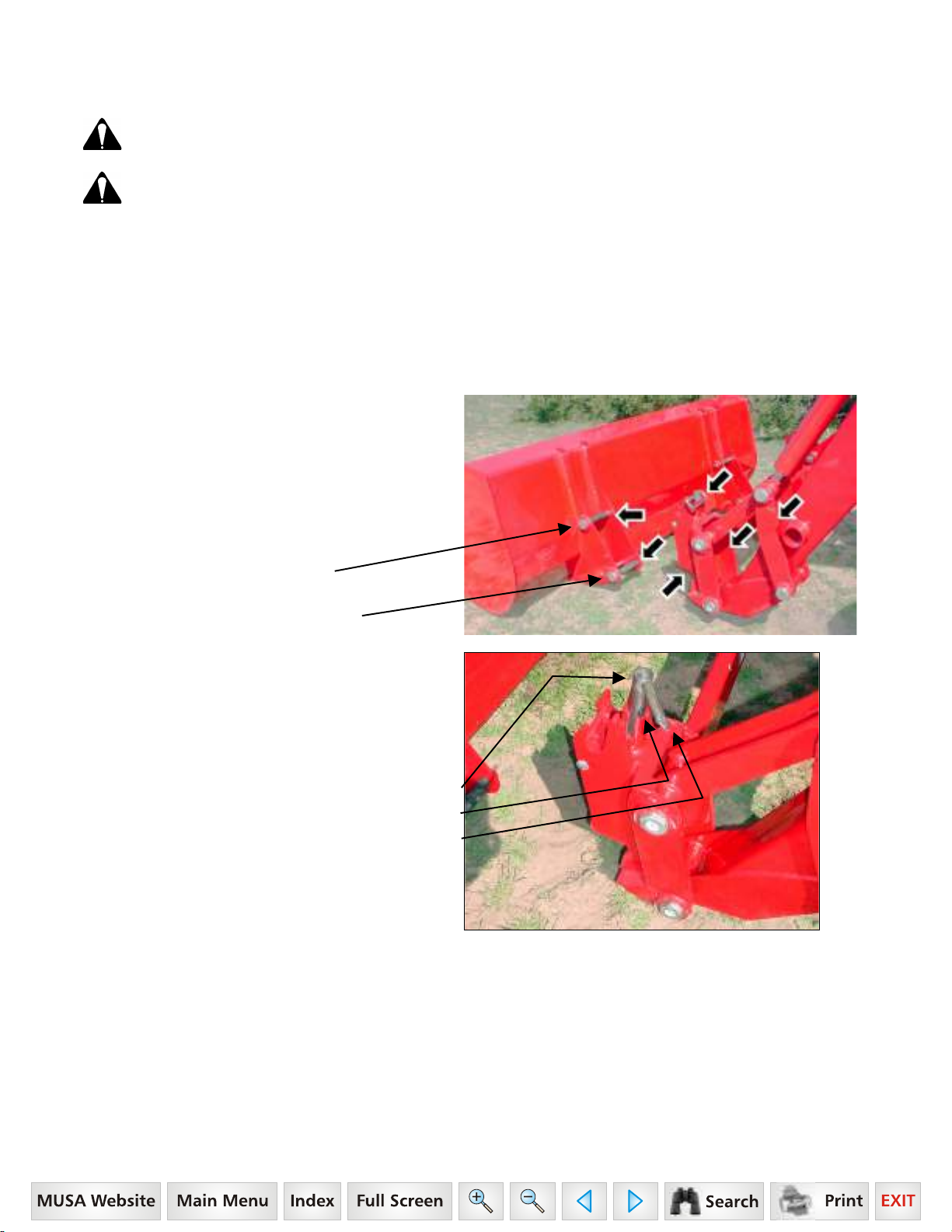
14. INSTALLING BUCKET OR ATTACHMENT
TO PIN ON QUICK ATTACH
CAUTION: Before leaving the tractor seat, stop the engine and lock brakes when installing or
removing bucket or attachment.
CAUTION: Do not stand, walk, or work under a raised loader or attachment unless it is securely
blocked or held in position. Accidental movement of valve handle/handles or leaks in the
hydraulic system could cause the loader to drop, or attachment to dump, causing severe injury.
14.1. RECOMMENDED LOADER FACTORY APPROVED ATTACHMENTS
14.1.1. Use only the following Loader Factory Approved Attachments for mounting on this Pin On Quick Attach
System.
♦
Pin On
Bucket 72"
♦
Pin On
Bucket 78"
♦
14.2. OPERATING INSTRUCTIONS
14.2.1. Make sure the following areas of Pin On
Quick Attach are clean (SEE WHITE ARROWS).
Pin On
Bucket 84"
♦
Pin On
Bale Spear
♦
Pin On
Pallet Fork
14.2.2. Install pin on quick attach direct to loader.
Secure using pins and e-clips.
Top Pin 1-1/8" x 7.01" and E-Clip,
1 place each side.
Bottom Pin 1-1/8" x 7.01" and E-Clip,
1 place each side.
14.2.3. To attach bucket or attachment to loader,
lower loader boom to ground with pin on quick attach
rolled forward slightly. Pull up on pin handle until
spring pin is above top bushing surface. Rotate pin
assembly slightly. Flip handle forward. Repeat for
other side.
Pin Assembly – pull up and rotate.
Spring Pin – resting on top edge of bushing.
Handle – flipped forward.
55
Page 57

14.2.4. Roll quick attach forward by extending tilt
cylinders just enough to allow pin on quick attach
receiver to engage bucket or attachment upper pin.
Drive tractor forward, aligning quick attach with
bucket or attachment.
Bucket or Attachment Upper Pin
Quick Attach Receiver – align with
bucket or attachment upper pin.
Quick Attach - roll forward and lower.
NOTE: Over extension of tilt cylinders during this
operation could cause damage to Pin On Quick
Attach handles due to handles contacting bucket
or attachment. Make sure handles are flipped
forward.
14.2.5. When pin on quick attach is aligned with pin
on bucket or attachment, raise loader boom slowly
making sure pin on quick attach receivers engage
attachment. Then roll quick attach back slowly.
14.2.6. Position loader so attachment is
approximately 1" off ground. Position pin assembly
into the engaged position by pulling up on handle and
rotating pin assembly so the spring pin is located in
bushing slot. Repeat for other side.
Pin Assembly – rotate pin assembly
so that spring pin is fully
engaged in bushing slot.
Attachment – approximately
1" off of ground.
56
Page 58

14.2.7. Check that bucket or attachment is securely
attached to pin on quick attach by raising loader
boom 3 to 4 feet, dumping bucket or attachment
against stops, and checking to be sure bottom of
bucket or attachment does not roll forward away from
pin on quick attach.
WARNING: A bucket or attachment that is not securely locked into Pin On Quick Attach could
come off during loader operation causing serious injury or death.
14.2.8. Inspect Pin On Quick Attach attaching
areas to verify that Pin On Quick Attach pins have
engaged bucket or attachment fully.
Spring Pin – fully engaged
in bushing slot.
Bucket or Attachment Lower Pin.
Pin On Quick Attach Pin Assembly
engaging bucket or attachment.
57
Page 59

15. REMOVING BUCKET OR ATTACHMENT
FROM PIN ON QUICK ATTACH
CAUTION: Before leaving the tractor seat, stop the engine and lock brakes when installing or
removing bucket or attachment.
CAUTION: Do not stand, walk, or work under a raised loader or attachment unless it is securely
blocked or held in position. Accidental movement of valve handle/handles or leaks in the
hydraulic system could cause the loader to drop, or attachment to dump, causing severe injury.
15.1. OPERATING INSTRUCTIONS
15.1.1. To disconnect bucket or attachment from
loader, position bucket or attachment slightly rolled
back and approximately 1" off of ground. Pull up on
pin handle until spring pin is above top bushing
surface. Rotate pin assembly slightly. Flip handle
forward. Repeat for other side.
Bucket or Attachment – rolled slightly back.
Pin Assembly – pull up and rotate.
Spring Pin – resting on top edge of bushing.
Handle – Flip Forward.
15.1.2. Roll bucket or attachment forward and lower
to ground. Back loader away from bucket or
attachment.
NOTE: Over extension of tilt cylinders during this
operation could cause damage to Pin On Quick
Attach handle due to handle contacting bucket or
attachment.
15.1.3. Position pin assembly into the engaged
position by pulling up on handle and rotating pin
assembly so the spring pin is located in bushing slot.
Repeat for other side.
Pin Assembly – Rotate pin
assembly so that spring pin is
fully engaged in bushing slot.
58
Page 60

16. SERVICE AND LUBRICATION FOR PIN ON QUICK ATTACH
16.1. KEEP THESE AREAS CLEAN
16.1.1. Keep these areas clean to allow pin on quick
attach system to function properly.
IMPORTANT: To maintain your Pin On Quick
Attach System functioning properly, always
inspect Pin On Quick Attach System components
for damage or wear. If damage or wear exists,
replace components immediately.
16.2. LUBRICATE ANNUALLY
16.2.1. Lubricate Quick Attach Pins annually using a
good grade of grease. Remove front covers of quick
attach by loosing 3/8" nut and then removing sealant
and cover plate. Grease components and pin and
then reinstall cover plate and seal using Sika-Flex
Sealant.
Lubricate these areas of Pin On Quick Attach.
Cover Plate shown removed.
Lubricate these areas of Pin On Quick Attach.
59
Page 61

17. OPTIONAL SKID STEER TOOL CARRIER SYSTEM
IMPORTANT: Read safety information in this section and on decal before operating attachment.
NOTE: Skid Steer Tool Carrier System is optional
equipment
WARNING: Always read and follow
operating instructions before operating
Skid Steer Tool Carrier System.
17.1. RECOMMENDED LOADER FACTORY APPROVED ATTACHMENTS
17.1.1. Use only Loader Factory Approved Attachments for mounting on this Skid Steer Tool Carrier System.
17.2. NON-LOADER FACTORY ATTACHMENTS
17.2.1. If you are going to connect a non-Loader
Factory Attachment to this Skid Steer Tool Carrier
System, read and understand the following
instructions and safety information. Always make
sure Skid Steer Tool Carrier is locked onto all
attachments.
NOTE "A": If your attachment back is not running
at a 20 degree angle, your loader rollback and
dump angles will change per attachment angle
change.
NOTE "B": If your attachment point is lower than
this, your attachment may not touch the ground
when loader is fully lowered.
60
Page 62

17.3. SKID STEER TOOL CARRIER SYSTEM SERVICE & LUBRICATION
IMPORTANT: To maintain
your Skid Steer Tool
Carrier System functioning
properly, always keep
handle components and
latching areas clean.
Keep all these areas clean.
Refer to 3 photos
at right and below.
IMPORTANT: To maintain
your Skid Steer Quick
Attach System functioning
properly, always inspect
Skid Steer Quick Attach
System components for
damage or wear. If damage
or wear exists, replace
components immediately.
17.3.1. Check and tighten
this 1/2" bolt after every 20
hours of operation.
17.3.2. A small amount of
light oil applied to pins
occasionally will improve
ease of function of skid steer
latching components.
17.3.3. Inspect latching
components and groove
pins. If damaged, only
replace with Factory
approved components.
61
Page 63

18. INSTALLATION & OPERATION OF
SKID STEER TOOL CARRIER SYSTEM
IMPORTANT: Read safety information in this section and on decal before operating attachment.
WARNING: Always read and follow operating instructions before operating Skid Steer Tool Carrier
System.
18.1. INSTALLATION INSTRUCTIONS
IMPORTANT: Do not extend bucket cylinders without Skid Steer Tool
Carrier installed on loader. Failure to follow these instructions could
cause loader damage and void warranty.
18.1.1. Install Skid Steer Tool Carrier to loader. Secure as shown.
Top Pin 1-1/8" x 7.01" and E-Clip, 1 place each side.
Bottom Pin 1-1/8" x 7.01" and E-Clip, 1 place each side.
18.2. SKID STEER TOOL CARRIER HANDLES IN DISENGAGED POSITION
18.2.1. To position handles into the
handle disengaged position, pull
skid steer tool carrier handle
upward.
Pull Handles
Upward
(1) Handles disengaged position.
62
Page 64

18.3. SKID STEER TOOL CARRIER HANDLES IN ENGAGED POSITION
18.3.1. To position handles into the
handle engaged position, push skid
steer tool carrier handle downward
until they latch into position.
Push Handles
Downward.
NOTE: Handles should be positioned parallel to ground if
properly latched.
IMPORTANT: If properly latched into skid steer tool carrier
attachment, the lower skid steer groove pin should be contacting
quick attach pin support bar.
(2) Handles engaged position.
(3) Groove pin.
(4) Contact point.
(5) Pin support bar.
63
Page 65

19. INSTALLING BUCKET OR ATTACHMENT
TO SKID STEER TOOL CARRIER
IMPORTANT: Refer to Pages 62 to 63 for instructions concerning Skid Steer Tool Carrier Handles
Disengaged and Engaged Positions.
CAUTION: Before leaving the tractor seat, stop the engine and lock brakes when installing or
removing bucket or attachment.
CAUTION: Do not stand, walk, or work under a raised loader or attachment unless it is securely
blocked or held in position. Accidental movement of valve handle/handles or leaks in the
hydraulic system could cause the loader to drop, or attachment to dump, causing severe injury.
19.1. OPERATING INSTRUCTIONS
19.1.1. To attach bucket or attachment to loader,
lower loader boom to ground with Skid Steer Tool
Carrier attachment rolled forward slightly.
19.1.2. To position handles into the
handle disengaged position, pull
skid steer tool carrier handle
upward.
Pull Handles
Upward
19.1.3. Roll Skid Steer Tool Carrier attachment
forward by extending tilt cylinders just enough to
allow Skid Steer Tool Carrier upper vee to engage
Skid Steer attachment vee channel. Drive tractor
forward, aligning Skid Steer Tool Carrier vee
components.
Align Skid Steer Tool Carrier vee
with Skid Steer Attachment vee channel.
NOTE: Over extension of tilt cylinders during this
operation could cause damage to Skid Steer Tool
Carrier handles due to handles contacting bucket
or attachment.
(1) Handles disengaged position.
64
Page 66

19.1.4. When Skid Steer Tool Carrier attachment is
aligned with bucket or attachment, raise loader boom
slowly making sure Skid Steer Tool Carrier vee
components engage. Then roll Skid Steer bucket or
attachment back slowly.
19.1.5. Position loader so attachment is
approximately 1" off ground.
19.1.6. To position handles into the
handle engaged position, push skid
steer tool carrier handle downward
until they latch into position.
Push Handles
Downward.
NOTE: Handles should be positioned parallel to ground if
properly latched.
IMPORTANT: If properly latched into skid steer tool carrier
attachment, the lower skid steer groove pin should be contacting
quick attach pin support bar.
19.1.7. Position loader so attachment is
approximately 1" off ground.
1" off ground.
(2) Handles engaged position.
(3) Groove pin.
(4) Contact point.
(5) Pin support bar.
65
Page 67

19.1.8. Check that bucket or attachment is
securely attached to Skid Steer Tool Carrier by
raising loader boom 3 to 4 feet, dumping bucket
or attachment against stops, and checking to be
sure bottom of bucket or attachment does not roll
forward away from Skid Steer Tool Carrier
Assembly.
19.1.9. Inspect Skid Steer Tool Carrier attaching
areas to verify that Skid Steer Tool Carrier pins
have engaged bucket or attachment fully.
19.1.10. Inspect Skid Steer Tool Carrier attaching
areas to verify that Skid Steer Tool Carrier pins
have engaged bucket or attachment fully.
19.1.11. Skid Steer Quick Attach (1) lower roll pin
should be contacting (2) Quick attach pin support
bar.
19.1.12. Skid Steer Quick Attach (3) pin should
be engaged into (4) bucket or attachment as
shown.
WARNING: A bucket or attachment that is not securely locked into Skid Steer Tool Carrier could
come off during loader operation causing serious injury or death.
19.1.13. If installing an attachment utilizing a third cylinder hydraulic circuit, connect loader hose quick couplers at
attachment quick couplers.
66
(3)
(4)
Page 68

20. REMOVING BUCKET OR ATTACHMENT
FROM SKID STEER TOOL CARRIER
IMPORTANT: Refer to Pages 62 to 63 for instructions concerning Skid Steer Tool Carrier Handles
Disengaged and Engaged Positions.
CAUTION: Before leaving the tractor seat, stop the engine and lock brakes when installing or
removing bucket or attachment.
CAUTION: Do not stand, walk, or work under a raised loader or attachment unless it is securely
blocked or held in position. Accidental movement of valve handle/handles or leaks in the
hydraulic system could cause the loader to drop, or attachment to dump, causing severe injury.
20.1. OPERATING INSTRUCTIONS
20.1.1. To disconnect bucket or attachment from
loader, position bucket or attachment slightly rolled
back and approximately 1" off of ground.
20.1.2. To position handles into the
handle disengaged position, pull
skid steer tool carrier handle
upward.
Pull Handles
Upward
20.1.3. Roll bucket or attachment forward and lower
to ground. Back loader away from bucket or
attachment.
NOTE: Over extension of tilt cylinders during this
operation could cause damage to Skid Steer Tool
Carrier handle due to handle contacting bucket or
attachment.
(1) Handles disengaged position.
20.1.4. If removing an attachment utilizing a third cylinder hydraulic circuit, disconnect loader hose quick couplers
from attachment quick couplers. Secure and store loader hoses on loader frame.
67
Page 69

21. SKID STEER BUCKET
IMPORTANT: Read safety information in this section and on decals before operating attachments.
WARNING: To avoid serious injury or death from large round or square hay bale handling:
Use only Factory bale spear or bale retaining device handler attachment when handling round
•
bales.
Do not handle large square bales without a retaining device handler attachment
•
Do not use buckets, forks, or other attachments without bale retaining devices.
•
Do not use loader for handling large, heavy objects such as logs, tanks, etc.
•
WARNING: To avoid serious injury or death, realize handling large heavy objects can be extremely
dangerous due to:
Danger of rolling the tractor over.
•
Danger of upending the tractor.
•
Danger of the object rolling or sliding down the loader arms onto the operator.
•
WARNING: To avoid serious injury or death:
Do not lift or carry anyone on buckets, forks, probes, or any other portion of the loader or
•
loader attachments.
Avoid contact with electrical power lines by loader or attachment
•
WARNING: Inadvertent movement of the loader or attachment could result in serious injury or
death.
21.1. SKID STEER BUCKET
21.2. INSTALLATION INSTRUCTIONS TO SKID STEER TOOL CARRIER
IMPORTANT: Refer to Pages 64 to 66 for instructions concerning Installing Attachment to Skid Steer Tool
Carrier.
IMPORTANT: Refer to Page 67 for instructions concerning Removing Attachment from Skid Steer Tool
Carrier.
68
Page 70

22. SKID STEER BALE SPEAR
IMPORTANT: Read safety information in this
section and on decals before operating
attachments.
IMPORTANT: It is not recommended that loader be detached with bale spear attached. Loaders will park
safely; however, bale spear could be damaged during parking. Always detach loader with bucket or other
loader Factory approved attachment attached.
CAUTION: When transporting a round bale, tilt the bale spear slightly back from level and carry
the load in a low position.
CAUTION: Never raise round bale to full height with bale spear rolled back as serious injury or
death could occur.
CAUTION: To prevent bodily injury, park and store bale spear with points pointed against bale,
building, or other stable object.
69
Page 71

22.1. SKID STEER BALE PROBE
IMPORTANT: This spear is a high strength alloy – drop forged steel and should not be welded or heattreated.
IMPORTANT: Maximum load limit on super penetrator bale spear is 2,000 pounds.
22.2. ASSEMBLY INSTRUCTIONS
22.2.1. Install Bale Spear into tapered sleeve and
secure with nut. Torque nut 515 ft. lb. Failure to
follow these instructions could cause damage to
spear and void your warranty.
(1) Upper Spear.
Flat surface of spear located upward.
(2) Tapered Sleeve.
(3) Upper Spear Nut, 28mm.
Torque nut to 515 ft. lb.
(3) (2) (1)
22.3. INSTALLATION INSTRUCTIONS TO SKID STEER TOOL CARRIER
IMPORTANT: Refer to Pages 64 to 66 for instructions concerning Installing Attachment to Skid Steer Tool
Carrier.
IMPORTANT: Refer to Page 67 for instructions concerning Removing Attachment from Skid Steer Tool
Carrier.
22.4. OPERATING INSTRUCTIONS
22.4.1. With bale spear level with ground, slowly
spear bale slightly above center.
22.4.2. With all three spears completely engaged into
bale, tilt bale spear slightly back from level and
transport the load in a low position.
Spear bale
slightly
above
center of
bale.
70
Page 72

23. SKID STEER PALLET FORK
IMPORTANT: Read safety information in this section and on decals before operating attachments.
WARNING: The pallet fork attachment is specifically designed to engage and load palleted
materials. Do not use forks to handle large loads such as bales, posts, etc. as they can fall or roll
back onto operator causing serious injury or death.
71
Page 73

23.1. SKID STEER PALLET FORK
23.1.1. The Skid Steer Pallet Fork has two tines each 1-1/2" x 4" x 42".
23.2. ASSEMBLY INSTRUCTIONS
23.2.1. Install (4) guard to (7) pallet fork frame using
(5) 1-2" x 1-1/2" bolt, lockwasher, flatwasher, and nut,
2 places each side.
23.2.2. Install (3) forks to (7) pallet fork frame using
(1) pins, 2 places secure using (2) 3/8" x 2-1/2" bolts,
lockwashers, and nuts, 4 places.
23.2.3. Locate (6) hooks on (3) forks on backside of
angle to prevent fork rotation.
23.3. INSTALLATION INSTRUCTIONS TO SKID STEER TOOL CARRIER
IMPORTANT: Refer to Pages 64 to 66 for instructions concerning Installing Attachment to Skid Steer Tool
Carrier.
IMPORTANT: Refer to Page 67 for instructions concerning Removing Attachment from Skid Steer Tool
Carrier.
23.4. OPERATING INSTRUCTIONS
The operator must keep the load centered and as far back on the forks as possible. Operator must always keep
load level. Carry the load low and at a slow speed.
23.5. PARKING INSTRUCTIONS
If parking loader from tractor with pallet fork attachment, move forks outward to widest position (see photo above).
NOTE: Move Forks outward to Widest Position
72
Page 74

24. TROUBLE SHOOTING PROCEDURES
This Trouble Shooting Chart is provided for reference to possible loader operational problems.
Determine the problem that best describes the operational problem being experienced and eliminate the possible
causes as listed by following the correction procedures.
For further assistance contact your dealer.
24.1. TROUBLE SHOOTING FOR ALL LOADERS
PROBLEM POSSIBLE CAUSE CORRECTION
Lift and Tilt Cylinders inoperative
Low hydraulic fluid level. Check and replenish hydraulic fluid.
Hydraulic hoses connected
improperly.
Hydraulic Hoses to/from loader
valve blocked.
Loader valve or tractor main relief
valve stuck open.
Low system pressure supplied from
hydraulic pump.
Loader valve linkage broken. Inspect. Repair as required.
Quick disconnect coupler(s) are not
fully connected.
Hydraulic hose or tubeline
blockage.
Cylinder piston assembly defective
(not sealing).
Loader valve blockage. Inspect for blockage. Disassemble
Check and correct hydraulic hose
connections
Check for damaged (kinked) hoses,
etc.
Check system pressure. Repair or
replace relief valve.
Check system pressure. Repair or
replace pump.
Check coupler connections.
Replace coupler(s) if necessary.
Check all hoses and tubes for leaks,
damage, or restrictions. Replace
damaged or restricted hoses or tube
lines.
Check cylinders for internal leakage
as described in service section
under cylinder leakage tests.
valve if necessary.
Lift and/or tilt cylinders operate
in wrong direction relative to
valve handle position
Attachment will dump but will not
rollback
Slow or erratic lift
Hydraulic hoses connected
incorrectly.
Hydraulic circuit connected
incorrectly.
Low hydraulic fluid level. Check and replenish hydraulic fluid.
Cold hydraulic fluid. Allow hydraulic system to warm up
Engine R.P.M. too slow (hydraulic
pump R.P.M. too slow).
Excessive weight in bucket. Material
weight exceeds maximum specified
loader capacity.
Loader valve linkage
binding/defective.
73
Correct hydraulic hose connections.
Refer to plumbing diagram on Page
32 and correct hose connections.
to operating temperature.
Increase engine speed to obtain
satisfactory loader operation.
Reduce material load.
Check loader valve linkage and
repair if worn/defective.
Page 75

PROBLEM POSSIBLE CAUSE CORRECTION
Aeration of hydraulic fluid Refer to "Aeration of Hydraulic
Fluid".
Quick disconnect coupler restriction
or coupler.
Hydraulic hose or tubeline
restriction (hoses/tubeline kinked or
pinched).
Lift cylinder piston assembly
leakage.
Relief valve erratic or set below
specifications.
Loader valve leaking internally.
(Bypassing fluid within valve.)
Inadequate hydraulic pump
capacity.
Inadequate lifting capacity Engine R.P.M. too slow. Increase engine R.P.M.
Excessive load – material weight
exceeds specified loader capacity.
Relief valve setting below
specifications.
Lift cylinder piston assembly
leakage.
Loader valve leaking internally. Replace loader valve and recheck
Check coupler connections. Repair
or replace.
Check hoses and tubelines for
evidence of restriction.
Check cylinders for leakage. Repair
as needed.
Check and reset relief valve setting
as needed.
Replace loader valve and recheck
operation.
Refer to "Hydraulic Pump Capacity
Inadequate".
Reduce Load.
Check and reset relief valve setting
as needed.
Check cylinders for leakage. Repair
as needed.
operation.
Hydraulic pump defective. Refer to "Hydraulic Pump Capacity
Inadequate".
Aeration of Hydraulic Fluid
(generally indicated by foamy
appearance of fluid).
Air leaking into suction side of
Hydraulic fluid foaming due to
System relief valve squeals. Cold Hydraulic Fluid. Allow hydraulic fluid to warm up to
Excessive load in bucket. Weight
Relief valve setting below
Hydraulic hose, tubeline, or quick
Low hydraulic fluid level. Check and refill hydraulic system to
proper level.
Check for loose or defective
hydraulic pump.
improper hydraulic oil usage.
exceeds specified loader capacity.
specifications.
disconnect coupler restriction.
connections between reservoir and
hydraulic pump.
Refer to Tractor Operator’s Manual
and replace hydraulic oil using
recommended hydraulic oil.
operating temperature.
Reduce load.
Check and reset valve setting as
needed.
Check for evidence of restriction in
hydraulic oil flow. Repair or replace
defective components.
74
Page 76

PROBLEM POSSIBLE CAUSE CORRECTION
Loader drops with loader valve
spool in "Centered" position (no
external oil leakage evident.)
Loader valve internal leakage. Replace loader valve and recheck.
Note: A gradual drop over an
Loader valve spool(s) will not
return to centered position.
Loader valve spool centering is
Loader valve spool binding in valve
Loader bucket moves freely after
dumping load
Contact Factory for optional orifice
External hydraulic fluid leakage. Loose hydraulic connection. Tighten loose connections.
Defective hydraulic hose, tubeline,
Cylinder Piston assembly leakage. Check cylinders for leakage.
extended period of time is a normal
condition.
Valve handle linkage binding. Determine origin of binding and
repair.
Replace centering spring.
broken.
Disassemble valve for inspection
body spool bore.
Tilt cylinder cavitation has occurred. Use of regen function while
adapter fitting or adapter fitting oring.
and repair.
dumping load will eliminate
problem. Refer to Page 32.
kit availability.
Check for origin of oil leak and
replace defective part.
Loader valve o-rings defective. Replace defective o-rings.
Loader valve spool or body
damaged or worn.
Cylinder rod packing set leakage. Check cylinders for leakage. Repair
Hydraulic pump capacity
inadequate.
Engine R.P.M. too slow. Increase engine R.P.M.
Low hydraulic fluid supply. Refer to Tractor Operator’s Manual
Hydraulic hose restriction. Check for evidence of restriction in
Hydraulic pump defective. Refer to Tractor Operator’s manual
Lift cylinder rods bend when lift
cylinders extended.
Bucket cutting edge wear is
uneven side to side
Cold hydraulic fluid. Allow hydraulic fluid to warm up to
Excessive shock load on lift
cylinders during transport.
Bucket is not level to ground. Check rear tire inflation and adjust
Replace loader valve.
as needed.
operating temperature.
for service recommendations.
hydraulic hoses.
for recommended service
procedures. Replace hydraulic
pump if determined to be defective.
Replace defective parts. Review
and observe proper and safe
operational practices.
to level bucket to ground.
75
Page 77

PROBLEM POSSIBLE CAUSE CORRECTION
Bucket cutting edge wear rate is
excessive. (Wear rate is even
across full width of bucket).
Bucket wear pads worn. Replace wear pads.
Note: Extensive use of bucket on
Loader is slow and/or will not
dump.
Oil filter plugged. Clean or replace filter.
Hydraulic pump worn. Repair or replace pump.
Oil line restricted or leaking. Check all hoses and tubes for leaks,
Loader valve does not shift
Cylinder leaks internally. Replace seals.
Faulty valve. Repair or replace valve.
Incorrect operational practices.
Excessive down pressure placed on
bucket when used on hard abrasive
surfaces.
concrete or asphalt surfaces will
accelerate wear rate of bucket
cutting edge.
Hydraulic oil too heavy. Change to proper oil.
properly.
Refer to operation – scraping
section for correct operating
procedures. Utilize float position.
damage, or restrictions. Replace
damaged or restricted hoses or tube
lines.
Inspect clean, repair, or replace
valve.
Loader chatters or vibrates when
raising or lowering.
Oil level too low. Add oil as required.
Slow leakdown. Worn loader valve. Have authorized Mahindra dealer
Worn cylinder piston seals. Have authorized Mahindra dealer
Attachment will dump but will not
rollback
Air in hydraulic system. Cycle lift cylinders and tilt cylinders.
replace seals.
replace seals.
Hydraulic circuit connected
incorrectly.
Check that Port "C" of loader valve
is connected to tilt cylinder base
end and that Port "D" of loader
valve is connected to rod end of tilt
cylinder.
76
Page 78

24.2. TROUBLE SHOOTING FOR LOADERS WITH OPTIONAL SELF LEVELING
PROBLEM POSSIBLE CAUSE CORRECTION
Bucket does not self-level
Bucket does not maintain level
while raising or lowering at
engine speeds other than high
idle.
Bucket does not maintain level
while raising at high idle.
Bucket does not maintain level
while lowering at high idle.
Excessive bucket drift in the
dump direction.
Bad float switch in the valve handle. Repair or replace the handle and
switch.
On-Off Solenoid Valve stuck in the
ON position.
Bucket self-leveling is designed to
work optimally at high RPM.
Loader valve lift spool not fully
stroked.
Flow divider spool stuck. *Check flow divider spool for free
Raise counterbalance valve stuck. *Remove and check for
Flow divider spool stuck. *Check flow divider cartridge for
Lower modulator valve stuck. *Remove and check for
Lift check valve stuck (cartridge). *Remove and check for
Bad bucket cylinder seal. Repack cylinder.
Raise counterbalance valve stuck. *Remove and check for
Check the Solenoid Valve on Self
Level Valve.
Run engine at high RPM (1700 or
above).
Fully stroke the loader lift spool.
operation. (Check for
contamination.)
contamination.
free operation.
contamination. (Spool should move
freely in bore.)
contamination.
contamination.
Bad Anti-Cavitation relief valve
cartridge.
Excessive loader control valve
bucket spool port leakage.
Bucket moves freely when
putting down pressure on cutting
edge.
Loader bounces with lowering
load.
Self-Leveling does not operate
after initial hook-up.
Self Level Valve Ports
*NOTE: This service must only be accomplished by an Authorized Mahindra Service Person. Failure to
follow these instructions will void warranty.
Pilot operator check is not closing
(cartridge plus pilot piston).
Low hydraulic flow. Increase tractor RPM to increase
Circuit not hooked up correctly. Check that circuits are hooked up
Self Level Valve Ports
to Loader Valve
1 5 Lift Base Green
2 6 Lift Rod Blue
3 7 Tilt Base Yellow
4 8 Tilt Rod Red
to Loader Cylinders
*Check Anti-Cavitation check valve
cartridge. Remove and check for
contamination or replace.
Check with Factory on acceptable
valve spool leakage rate. Replace if
required.
*Remove and check for
contamination. Replace if required.
hydraulic flow.
as follows.
Circuit Color Tag
77
Page 79

25. TORQUE CHART
78
 Loading...