

Page 1

JINMA SERIES TRACTOR
OPERATION MANUAL
JINMA-200
JINMA-204
JINMA-250
JINMA-254
JINMA-300A
JINMA-304A
MAHINDRA YU EDA
(YANCHENG) TRACTOR CO.,LTD
.
Page 2

1
Preface
Jinma series wheeled tractors
(、、、、
JM-200 JM-204 JM-250 JM-254 M-
、)
300A JM-304A
are small four wheel tractors of new type , which are developed
according to the increasingly rising demands of dometic and overseas agricultural
machinery for small new wheeled tractors . The tractors have the characteristics of
saving energy , high efficiency , varied purpose ,beautiful appearance . If you buy
them , you wil l get satisfactory economic pro fit from them .
Jinma series wheeled tractors respectively adopt vertical and energy saving
,,
diesel engine of 20 25 30Hp as their power ;th ey employ direct gears transmission
betwee n engine and transmi ssion syst em . Jinma tractor s have m any types for you t o
choose . They not only have single stage clu tch and dual stage clutch types , but also
have two wheel and four wheel driv e types .They also have creeper devic e for you to
choose if you want your tractors to conduct ditching operation . They have perfect
hydraulic suspension system in performance , wide thread driving tyres of good
adhesive force and low pr essure and reli able (crankp in type and circula ting ball type )
but also have hydraulic steering gear , the users can choose either of them . The
products are featured by their favourable power ,relatively hight traction force ,
compact contruction , high transmission efficiency ,easy operation , convenient repair
and maintenance ,economical oil consupmtion ,easy attachment of implements and
good compreshensi ve usage .
In order to help the customers master the Jinma series tractors' operation ,
adjustment and maintenance , and prolong their service life , make the best possible
use of th em and o btain idea l economi c profit ,we compile the operation m anual ,With
regard to the operation and repair and maintenace , Please consult the operation
manuals of th e diesel engines .
With the development of science and technology and varying in requirement of
customers , the tractors are subject to improvements and perfection in their in their
construction s which will be written about in next editions of the manual . Therefore ,
users of tractors are required to pay attention to where the manual differs from the
actual tractors .
Page 3

2
Precautions
1. Drivers should read the operation manual carefully and be familiar with the
performance, operation and maintenance of the tractor. Otherwise we will not be
responsible for any qua li t y problems ca used by improper ope r ation.
2. Never fill the fuel tank with unfiltered or un-precipit a ted fuel.
3. New tractors must undergo running according to the regulat ions befo re they are
put into use.
4. It is prohibited to turn sharply with one-side braking while tractor runs at high
speed in or de r to avoid overturning or parts damage.
5. Bolts or nuts of wheel disc and of other important parts should be checked
regularly and be tighten ed if they are loos e.
6. During transferring the tractor with a mounted implement, it is not allowed to
drive the tractor at high speed in order to avoid damaging hyd raulic lift system and
suspension system.
℃
7. After opera tion at the area of below 0 in winter, the water sh ould be dra ined
out at idle speed in order not to freeze and damage the tractor parts (not including antiicing fluid).
Page 4

1
CONTENTS
……………………………………………………………………………………………
Prefac e (1)
………………………………………………………………………………………
Precautions (2)
Ⅰ ………………………………………………………………
Chapt er Main Specifications (1)
Ⅱ ……………………………………………………………
Chapter Oper ating the T ra cto r (5)
…………………………………………………………………
1.Fuel and lubric ating oi l (5)
……………………………………………………………………………………
2.Water (6)
……………………………………………………………
3.Ru nning-in of unused tractor (6)
………………………………………………………………
4.Co ntro ls an d ins trum en ts (8)
…………………………………………………
5.Control and operation of the tractor (10)
………………………………………
6.Con tro l and op erat ion of the w orkin g dev ice s (14)
……………………………………………………
7.Use of t he e lectri cal e quip ment (16)
Ⅲ …………………………………………
Chapter Technical Main te na nc e of the T ra ctor (19)
………………………………………………………………………
1.Shift ma intenance (19)
………………………………………………………………
2.First class maintenance (19)
………………………………………………………………
3.Second class maintenance (20)
………………………………………………………………
4.Thir d class m ain te nance (20)
………………………………………………………………
5.Fourth class maintenance (20)
…………………………………………………………………
6.Maintenance in winter (21)
………………………………………………
7.Maintenance for storage of a long time (21)
Ⅳ ……………………………………………………………
Chap ter Adjustment of Tractor (22)
……………………………………………………………………
1.Ad justment of clutch (22)
………………………………………………………………
2.Ad justment of m ain drive (24)
………………………………………………………
3.Adjust me nt of d ifferential lock (27)
……………………………………………………………………
4.Adjustment of brake (28)
………………………………………………………………
5.Adjustment of front axle (30)
…………………………………………………………
6.Ad justment of front drive axle (31)
……………………………………………………………
7.Adjust me nt of w h eel tre ad (33)
………………………………………………………
8.Adjust ment of steering gear (34)
……………………………
9.Construction and adjustment of hydraulic hitch system (39)
…………………………………
10.Use and ad ju stme nt of ai r br ake d evi ce of tra il er (46)
Ⅴ ……………………………
Chapter Main Troubles of Tractors and Trouble Shooting (49)
…………………………………………………………………………………
1.Engine (49)
…………………………………………………………………
2.Tran sm is sion sy ste m (51)
Page 5

2
…………………………………………………………………………………
3.Brake (52)
……………………………………………………
4.Steering gear and walking system (53)
……………………………………………………………
5.Hydraulic hitch system (54)
……………………………………………………………………
6.Electrical system (55)
……………………………………………………………………
7.Electrical system (56)
Ⅵ …………………………………………………………………………
Chapter Appendix (59)
………………………………………………
1.Wiring diagram of the electrical system (59)
……………………………………………………
2.Accessaries for customers to order (59)
3.Dis tribution diagram of rolling bearing
………………………………………
and transmission system of JM series tractors (61)
…………
4.Specifications and distributions of oil seals in JM series tractor's chassis (63)
……………………………………………………………………
5.Sizes of hitch system (65)
…………………………………………
6.OECD approval No. of JM series tractors (67)
Page 6

Ⅰ
Chapter Main Specifications
Model JM-200 JM-204 JM-250 JM-254 JM300A JM304A
Type ×42wheeled ×44wheeled ×42wheeled ×44wheeled ×42wheeled ×44wheeled
Overall
dimen-sions
(mm)
Length
Width(without ballast)
Heitht(to steering wheel)
3080
1250/1410
1910
3080
1250/1410
1910
3080
1280/1440
1930
3080
1280/1440
1930
3200
1280/1440
1930
3200
1280/1440
1930
Wheel base (mm) 1465 1510/1560 1587.5 1588
Wheel tread
(mm)
Front wheel
Rear wheel
1070 -1270
1040-1200
950 / 1050
1040-1200
1070 -1270
1040-1200
950 / 1050
1040-1200
1070 -1270
1040-1200
1050
1040-1200
Ground clearance (mm) 330 275 340 340
Turning radius
(m)
With one-side braking
without braking
±2.4 0.2
±2.8 0.2
±2.8 0.2
±3.0 0.2
±2.75 0.2
±3.0 0.2
±2.8 0.2
±3.0 0.2
±2.75 0.2
±3.0 0.2
±2.8 0.2
±3.0 0.2
Weight
(kg)
Construcional weight
Min.working weight
1040
1160
1140
1270
1040
1060
1140
1270
1170
1290
1270
1400
()
Rated traction force N 4000 4800 5200 5980 5200 5980
()Normal speed km/h six six six six eight eight
:Forward 1 st
2nd
3rd
4th
5th
6th
7th
8th
:Reverse 1st
2nd
1.99 0.37
3.94 0.73
6.57 1.22
9.21 1.72
18.2 3.39
30.36 5.66
1.58 0.29
7.3 1.36
1.68 0.31
3.31 0.62
5.52 1.03
7.75 1.45
15.3 2.85
25.5 4.76
1.33 0.29
6.15 1.15
2.06 0.38
4.07 0.76
6.79 1.27
9.52 1.78
18.8 3.51
31.4 5.85
1.63 0.30
7.55 1.41
1.73 0.32
3.42 0.64
5.71 1.06
8.01 1.49
15.8 2.59
26.4 4.92
1.37 0.26
6.35 1.18
2.12
3.24
5.08
7.00
9.82
14.97
23.49
32.38
2.79
13.52
1.77
2.69
4.23
5.83
8.18
12.46
19.56
26.96
2.32
11.25
Engine
Model LL380 LL380 KM385 KM385 ZN390T ZN390T
Type 3 cylinder ,vertical ,water - cooled , 4-stroke
1
Page 7

Model JM-200 JM-204 JM-250 JM-254 JM300A JM304A
Engine
12-hour power(kW)/rated speed r.p.m 14.7 14.7 18.4 18.4 22.1 22.1
×Bore Stroke(mm) ×80 90 ×80 90 ×85 90 ×85 90 ×90 95 ×90 95
Fuel consumption (g/kw·h) ≤ 245 ≤ 245 ≤ 245 ≤ 245 ≤ 255 ≤ 255
Oil consumption (g /kw·h) ≤ 2.0 ≤ 2.0 ≤ 2.0 ≤ 2.0 ≤ 2.72 ≤ 2.72
Net weight (kg) 250 250 250 250 230 230
Transmission
Clutch Single disc,dry-friction constant mesh OR Dual stage ,gear operation
Gear box (+)× ( )×Supr gear 3 1 2 compound , or supr gear 4+1 2compound Creeper can b chosen
Intermediate drive ×1 2 spiral bevel gear
Differential Closed with 2 planetary bevel gears
Diffierential lock Claw type
Final drive Internally meshed single spur cylindrical gear
Walk
and
operatin
g system
Frame type Frameless rigid connection
Front axle type
inverted U pipe
balancing arm
side bevel gear
drive
inverted U pipe
balancing arm
side bevel gear
drive
inverted U pipe
balancing arm
side bevel
gear drive
Pendulum angle of front axle °12 °8 °12 °8 °12 °8
Tyres
Front wheel
Rear wheel
4.00-16
8.3-24
6.00-12
8.3-24
5.00-15
9.5-24
6.00-16
9.5-24
5.00-15
9.5-24
6.00-16
9.5-24
Tire infation
(pressure kPa)
:Front wheel
:Rear wheel
()in field
()transport atio n
200-250
100-120
120-140
180-200
100-120
120-140
200-250
100-120
120-140
180-200
100-120
120-140
200-250
100-120
120-140
180-200
100-120
120-140
Steering gear
sphere worm steering
Hydraulic steering gear may be chosen for all models
Brake Foot - controlled shoes type Disc type
2
Page 8

Model JM-200 JM-204 JM-250 JM-254 JM300A JM304A
Hydraulic
systems
Type Half remote
Hydraulic pu mp
CBN-E306
gear pump
CBN-E306 / 314
gear pump
CBN-E306
gear pump
CBN-E306 / 314
gear pump
CBN-E310
gear pump
CBN-E310
gear pump
Hydraulic cylinder
×Horizontal single− acting type63 100(mm)
Distributor Slide valve regulating type
Safety valve Direct-acting type
×Rated lifting capacity (N mm) ×3600 610 ×3900 610 ×4200 610 ×4200 610 ×5000 610 ×5000 610
Safety valve release pressure(MPa) ~+16 ( 0 1.6 )
Suspension
mechanism
Connection type of implements rear mounted - point hitch category 0 Ⅰrear mounted - point hitch category
Upper link-hole diameter(mm)
×φ19.5 44
Lower link-hole diameter(mm)
×φ22.5 35
Traction
device
Traction ground clearance(mm) 470 495
Traction pin diameter(mm) Φ20
Power-take-
off
Rear P.T.O shaft ,Nonindepender 540r/min or semi-independent 540r/min dual speed(540r/min ,1000r/min)can be chosen
Electrical
equipments
and gauges
System 12V ,negative pole connected with iron , single phase circuit
Starter 、12V 2.5kW or 3.0kW
Generator 14V 350W
Battery 6-Q(A)-80,80A·h
3
Page 9

Model JM-200 JM-204 JM-250 JM-254 JM300A JM304A
Electrical
equipments
and gauges
Ammeter +() -30~0~ 30 A
Oil pressure gauge ()12V 0~0.5 MPa
Water temperature gauge ℃ 12V (40~100)
pressure gauge 0~1.0 MPa
Head lamp ND118-80T , 20/8W 12V
Rear light WD115-2 , 20/8W.12V
Direction light FT12 , 8W.12V
Electric horn DL87-12
Main filling
capacity (L)
Fuel tank 19 19 19 19 24 24
Engin e oil sump 5
Front drive axle ─ 4.5 / 6 ── 6 ── 6
Transmission box 11 14 11 14 11 14
Lifter 9 14
Steering gear 0.4
Cooling water 10 or 12
4
Page 10

5
Ⅱ
Chapter Operating the Tractor
1.Fuel and lub r icating oil
1) For fuel and lubricating oil for the tractor see Table 2-1.
Table 2-1 Fuel and lubricating oil for the tractor
2) Cautions for filling fuel
Using clear diesel fuel is an important factor to prevent troubles in engine and
prolong the engine's service life. The followings should be observed during filling fuel:
A. Fuel mus t be deposited for over 48 h ours before fuel tank is fill ed with it. Fu el at
the bottom should not be poured into the fuel tank.
B. Filter fuel when filling fuel tank with it.
C. Fuel filling devices must be kept clean.
D. Fuel tank and f uel filte r should be cleaned regularly, and deposited fuel should be
dra ined out.
Component Season and ambient temperature Oil specificatio n
Fuel tank
Summer (ambient temp. above10
℃ )
No.0, -10 light diesel fuel
GB252-87
℃Winter (ambient temp. below10 )
No. -20 light diesel fuel
GB252-87
Engine sump
Lifter
Oil pa n of air cleaner
Injection pump
Hydraulic steering gear
℃Ambient temp. below 0
No. 20 diesel engine oil
GB5323-85
℃Ambient temp. at 0-25
No. 30 diesel engine oil
GB5323-85
℃Ambient temp. above 25
No. 40 diesel engine oil
GB5323-85
Transmission box
Transfe r c ase Front drive
axle Mechanical steering
gear
Summer (ambient temp. above10
℃ )
No. 40 diesel engine oil
GB5323-85
℃Winter (ambient temp. below10 )
No. 30 diesel engine oil
GB5323-85
Grease nipple Without consideration of season
No. ZFG2 calcium base
compound grease
ZBE 36003-88
Bearin g 60203Gen erator
and starter
Without consideration of season
No. ZFG2 com p ou nd
calcium base grease ZBE
36003-88
Page 11

6
2.Water
1)Radiator should be filled with clean soft water so as to eliminate scale in the engine
cooling
syst em whic h wil l re duc e coo lin g effi cie ncy. On ly aft er b eing soft ene d can hard water su ch a s
well water, spring water, etc. be used. Method for softening hard water is as the follows:
A. Boil hard water, then deposit for some time and filter.
B. Put 1.5g of caustic soda into one lit of hard water. When operating the tractor in cold
weather, add cooling water with f re ez e - p ro of li q ui d.
3. Runn ing-in of unuse d tractor
The unused or overhauled tractor can not be put into operation unless it has undergone
running-in. Otherwise its performance will be affected and service life wi ll be shortened.
1)Prep arations before running-i n
A.Clean the outside of the engine.
B.Inspect outside bolts and nuts, and tighten them if necessary.
C.Check the lubricating oil level, and refill to stipulated level if insufficient.
D.Inject grease into lubricating points.
E.Fill with fuel and cooling water
F.Check toe-in (4-10mm) and tire inflation pressure, readjust or reinflate if necessary.
G.Inspect the connections of battery and wires of electrical system.
2)Idle running-in of the engine
After t he engine is started i n accorda nce with specified steps, list en carefu lly and make
sure whether there is abnormal sound, check for leakage of water, air, oil and the readings of
the gauges. When it is made sure that the engine is in normal working condition, the next step
of runn ing-in can be proceeded.
The unlo aded ru nnin g- in l asts 1 5 min ut es, the first 7 minu te s with m inim um th ro ttl e, then
medium throttle for other 5 minutes and then lasts 3 minutes with full throttle.
3)Unloaded and loaded running-in of the tractor
The running-in of the tractor should be done at rated engine speed. The order and time of
running-in should be done according to the standard in Table 2-2.
Page 12

7
Table 2-2 Ru nning-in standa rd of the tractor
Matters needing att ention during running-in process:
A.Chec k on whether the engine runs normally.
B.Check on whether the adjustment of the clutch is normal and the disengagement is
complete.
C. Check on whether the gear shift of the gearbox (including front drive handle,
creeper) is light a nd flexible , and th ere is any a ut om atic gea r d isengag em ent and gear- shiftin g
lock.
D.Check on the function or reliability of the brake.
E.Check on whether the steering gear is flex ible.
F.Chec k on whether the gauges and elect rical equipments are normal and reliable.
During the running-in process, if any abnormal phenomena or failures appear, the
cause should be found out and corrected, then the running-in can be carried on.
After the running-in is completed, the tractor must be undergone the following
maintenance before being put into operation:
A. After the tractor has been stopped, drain out the lubricating oil in the engine sump
while i t is still war m. Wash the sump and oi l filter with diesel fuel . After the di esel fuel has
bee n out, refi ll the sump with new lubricating oil to sp ecified leve l.
B. Drain out the lubricating oil in the transmission box, hydraulic system and front
drive ax le while it is still warm. Th en fill th em with di esel fu el of pro per quan tity an d run the
tractor in 2nd forward and 1st reverse gears for 2-5 minutes for cleaning. As soon as the
tract or is stop ped, dr ain out th e diesel f uel imm ediately and then refil l new lubr icating oil to
specified level.
C.Clean fuel filt er (including filter cartridge in fuel t ank) and air cleane r.
D.Drain out cooling water, clean the cooling system of engine with clean water.
E.Check on and adjust the f ree travel of clutch pedal, the travel of brake pedal and the
Running-
in type
Load
Running-in hours per gear Total Sum
1st 2nd 3rd 4th 5th 6th R1st R2nd
Unlo aded Tract or only 1 1 1 1 0.5 0.5 0.5 0.5 6
Loaded
With trailer
loadedwith 1.2T
goods onhighway
transporta- tion
124422 15
31
Fitted with plough at
plough depth about
13.3 cm in lig ht so il
1243 10
Page 13

8
working condition of the brake.
F.Check on and tighte n the nuts and bolts on all connection positions.
G.Check on injector and valve clearance, adjust them if necessary.
H.Check on working c onditions of el ectrical syst em.
I.Check on and adjust the toe-in of front wheel.
J.Inject grease into each lubricating point.
4. Controls and instr uments
In ord er to opera te the trac tor correct ly, it is nec essary t o familiar ize the func tion of
all controls and instruments as well as their positions on the tractor (Fig.2-1).
1) Auxiliary gear shifting lever: To control the auxiliary speed gear. (Fig.2-2).
2) Main gear shifting leve r: To cont rol the main spee d ge ar. (Fig.2- 2).
3) Ge ar shiftin g pattern p late: It i s located o n the top of gearbo x cover to show the
positions of gear shifting lever.
4) Con trol le ver o f fr ont d rive a xle: Enga ge o r cut off the p ower of fro nt dr ive axle to
achieve 4-wheel drive or 2-wheel drive.
5) Steerin g wheel: It con t r ol s the di rec tio n of tractor runn in g.
6) Clutch pedal: Depress the peda l, then the clutc h is di sengaged.
7) De com pres si ng le ve r: Redu ce t he pres su re i n t he c ylin d ers t o ma ke the en gine st art
easier.
8) Extinguishing lever (Fuel cut-off rod): To make the engine stop.
9) Single-position switch: Pull the switch out, the rear work light is turned on and
push the switch in, it is turned off.
10) Turning signal switch: Turning the switch to the left or right, the left or right
turning signal light will flash to show in the left or right turning.
11) Horn butto n: Press the butt on to sound the hor n, and it will send out alarm signal s.
12) Ammeter: It indicates the current intensity of battery while being charged or
discharged. If t he p ointer de fle cts to " + " side, it m e an s that the b at ter y is being charg ed ; if to
"-" side, it is being discharged.
13) Water temperature gauge: Indicates the water temperature of the engine cooling
system.
14) Tachometer :It irdicates the speed and accumulated working time of the engine.
Air pressure meter : It indicates the air pressure of the brake system(fror 2WD).
15) Oil p ressure gau ge: It indi cates the oil pressu re in main oil lines of th e engine , the
normal oil pressure is 2- 4 kgf/cm
2
(0.2-0.4MPa).
16) Fuel gauge: It indicates the fuel level of the fuel tank.
Page 14

9
Fig.2-1 Controls and Instruments
Page 15

10
17) Two-position switch: Pull the switch to the first position, the headlights (lower
beam) will be lighted, to the second position, the full-beam of the headlights will be lightened.
18) Starting switch: It has two functions: one is for switching on or off the circuit
current and the other is as electrical starting switch.
19) Hand th rottle: Pull the h and throt tle backward, the fuel flow will increase whil e
push it forward, fuel flow will decrease.
20) Creeper shift ing lever: To exchange the normal sp eed and creeper speed.
21) Left and right brake pedals: Turn the braking lock plate right to make left and
right pedals connect with each other and brake at the same time; while separating the
braking lock plate can achieve left or right one-side brake, then one-side brake and turn can
be made.
22) Foot throttle peda l: Depress th e pedal down, the fuel flow w ill increase ; loosen it,
the fuel flow will decrease.
23) Pa rking brake lock pawl: Put the b rake lock pawl on the le ft brake pedal into the
teeth of the brake teeth pla te at the right side of transmission box to keep the brake for a long
period.
24) P.T.O contr ol lever: En gage or dise ngage P.T.O power.
25) Differential lock lever: Used to move right claw to make differential lock
disen gaged or engaged so that the two driving wheels have different speeds or not.
26) Hydr aul ic cont rol lever: When th e lev er is pu shed or pu lled backwa rd, fo rwar d or
into vertical position respectively, the hitch is lifted, lowered or in neutral position.
5. Control and ope ration of the tractor
1) Starting engine
Before starting the en gine, ch eck fuel, lu bricating oil and coo ling water. Check and make
sure ev ery co mpone nt an d electri cal syste m work corre ctly, d rain out th e air in the fu el lines ,
put gear shifting lever in neutral position. If the hydrauli c system is installed on the tractor,
caution: check whether enough hydr aulic oil is filled in the lifter housing.
After the prestarting preparation, start the engine.
A.Set to decompress and rotate the engine crankshaft several turns with the hand
starting handle, check and make sure all moving parts work correctly, and pump oil to
surfac es of mo vi ng par ts.
B. When starting the engine with the hand starting handle, set the hand throttle to full
open position, put the decompression lever to the decompression position, accelerate the
crank ing, the e ngine w ill be st arted along wi th the d ecompres sion lev er ret urn aut omatica lly
to original position.
Page 16

11
C. When switch starting, set the decompression lever to decompression position too.
Turn the
startin g switch clo ckwise to "start" p osition, thus the e ngine is d riven by starter, th e starter
must n ot b e operat ed more than 5-10 sec. for ea c h start. On l y af t er a n interv al o f no t l e ss than
2 minutes can the engine be started again.
D. When switch starting is s uccessf ul, turn the sta rting switch countercl ockwise to th e
charging position of battery.
E. It is not necessary to decompress the engine while switch start ing in summer. Filling
the ra diato r w ith hot w a ter or th e oi l sump with h ea ted e ng in e o i l ca n b e us ed a s s tar tin g aids
in winter.
2) Starting the tractor
After the en g i ne i s star te d , run it at mo de rate s p eed for 5 - 10 min utes for war m -up itself, a f te r
℃
thewater temperature reaches above 70 , tractor can be started according to following
steps:
Page 17

12
A.Lift the implement.
B.Dep ress t he clut ch peda l, pu t t he ge ar sh ift ing l ever i nt o the desi red low er ge ar, rele as e
the parking brake lock pawl of the brake pedal.
C.Observe the environment to confirm that there are no obstructions on the road and
sound the horn to call atte ntion to the people.
D. Incr ease the engine sp eed gradu ally and si multaneo usly rele ase clut ch pedal s o as to
make the tractor start off smoothly
.
3) Operating the tractor
A.During operation make sure that readings on gauges are normal.
B.It is prohibited for oper ator to place his foot on clutch pedal so as to protect clutc h from
beingdamaged because of semi-engaged condition of clutch.
C. In transportation or running on highway, lock the left and the right brake pedals
together with brake lock plate.
D. In field operation, one-side braking can be used to reduce turning radius, but it is
prohibited to use one-side braking for sharp turning when the tractor is running at high
speed or is used for transportation on highway, so as to prevent overturning and protect
comp onents from being damaged.
E. Proper speed should be selected to get best productivity. Table 2-3 shows the speeds
for various operations.
Table 2-3 Speeds for different operations
Operation Gear
Creeper Ditching
L1st Rotary cultivation
L2nd Rotary cultivation, transportation
L3rd Ploughing, harrowing, drilling
H1st Ploughing, harrowing, drilling
H2nd Transportation
H3rd Transportation
R1st To attach implemen ts
R2nd To attach implements
Page 18

13
4) Stopping the tractor
A. Throttle the engine down to lower the speed of the tractor.
B. Depress the clutch pedal quickly and shift the gear-shif ting lever to neutral position.
C. Release the clutch pedal and let engine run idle.
D. Depress the brake pedals to stop the tractor, th en lock the pe dals with the lock pawl.
Note:
In case the tractor has to be stopped suddenly, clutch pedals and brake p edals
should bedepressed s imultaneously. It is pro hibited to depress th e brake pedals only, whi ch
will damage the parts.
E. If the tractor is to be parked for quite a while, the engine should be stopped. After the
engine has been u nloaded, it should run at l ow speed for som e time un til the cooling wate r
temperature drops to
℃
70 or lower, then pull out fuel cut-off rod to bring the engine to a st op.
Note:
It is prohibited to stop the engine at once when its temperature is very high, or to
stop the en gin e wi th decompress ion mecha nism.
F.Turn the preheating/starting switch to "O" and pull out the key. If the tractor is going
to be stored, turn off the fuel tank cock.
℃
G.If the tractor is stopped when the ambient temperature is below 0 , screw of the
radiator cap and turn on the water-drain cock on the bottom of the radiator and on the
cyli nder bl ock t o drain out wa ter a t idle en gine speed s o as to prote ct the b ody an d radi ator
from being froze n (n ot inc luding ad ding anti -icing fluid).
5) Safety regulat ions for operati on
Safety regulations are very important for protecting drivers and tractors from hazard.
They should be obser ved strictly in operation .
A. Inspect carefu lly th e work in g cond iti o n of the engine and ma in compon ents, an d listen
to whether there is abnormal sound or noise. Especially observe the technical state of clutch
and brake. Check and tighten the bolts and nuts on main components of the tractor.
B. Make sure that there is no people or obstacle around the tractor and press horn
button beforestarting off the tractor.
C. Don 't go up a nd do wn t he tra ctor duri ng ru nnin g. Never m ake check or re pair un der
the tractor wh ile the en gin e is still running.
D. Before the tractor goes up or down a slope, proper speed should be selected and don't
coast, turn sharply or shift gears while driving down a slope.
E. In transportation, left and right brake pedals must be locked together. One-side
brakin g can not be used for sharp turning when the tractor is running at high speed or with
full load.
Page 19

14
F. If front en d o f th e tr actor rises up in operat ion , th ro ttl e d ow n the e ng in e, d ise ngag e th e
clutch and reduce the load to protect the tractor from longitudinal overturning.
G. If the engine runs away, immediately pull out the fuel cut-off rod, move
decompression lever to "decompressing" position or plug up fresh air into the engine instead
of disengage clutch .
H.Ligh t ening equipment must work well during operat ion at night.
I.Co ntrol le ver sho uld b e placed in the ne utra l posit ion whe n the fo ur-whe el driv e trac tor
is running idle or being used for transportation.
6. Control and operation of the working devices
1)Control and operation of PTO
PTO can be engaged and disengaged by means of operating the PTO control lever on the
right side of the transmissi on box.
The speed of PTO is 540 rpm or 540 rpm and 1000rpm. When push down (from front and
upper side) the control lever, PTO is engaged; while pull upper the control lever, PTO is
disengaged. The operation steps are as follows:
A. Remov e the PTO sa fet y shield an d draw bar, coup le th e desir ed driven ma chin e to th e
PTO shaft.
B. Put the gear shifting lever at the neutral position.
C.Depress the clutch pedal fully, then shift the PTO control lever to the "engaged"
position.
D.Release the clutch pedal slowly and the driven machine will run. First let the driven
machine run at slightly open throttle for a while to ensure that nothing is wrong with the
driven machine. Then make the throttle wide open and put the driven machine into operat ion.
Note: Wh en the tracto r with implemen t travels fo r a long distanc e, should shif t the contro l
lever to neutral position to cut off the power so as to avoid damaging the implement and
causin g body acci de nt.
2)Control and operation of hy draulic hitch sy stem
Hydraul ic hitch sy stem serves to attach, lift and lower implement, as wel l as adjust and
maintain the working pos ition of implement, so a s to meet different re quirements of va rious
implements and operations.
Move the control lever of the distributor to raise and lower the implement.
According to the type of work to be done, type of implement used and field condition,
hydraulic hitch system provides various functions, so that the satisfactory work quality is
obtained.
A.Posi tion control
In po sition co ntrol, by means of mo ving cont rol lever of the d istribu tor, the p osition of
Page 20

15
implement could be adjusted, if desired position of the implement has been got, set the
position of the stop per on th e return rod to limit t he contr ol lever. T ight en the sto pper on the
rod with screw, so that th e lever can be push ed to the s ame position every ti m e.
Adjustment may be done during plowing period. The supporting wheel for the implement is
not necessary in position cont rol.
B.Floating contro l
Floating control is suitable for field plowing. In floating control, supporting wheel is
needed for implement, During plowing , hold the control lever of distributor at "lowering
position. (i.e. push the control lever of distributor forward with the return stopper. Do not
return the control lever to the neutral position). The hydraulic circuit is in "floating" control.
Using floating control, the plowing depth is controlled by the change of the height of the
supporting wheel. The uniform plowing depth would be obtained in the field with wild
changes of soil resistance.
C.Control of the lowering speed of the implement
Turn the lowering speed adjusting valve to control the lowering speed of the implement.
The lower ing sp eed sh ould be sele cted prope rly ac cordi ng to th e weig ht of the i mplem ent and
hardn ess of soil surfa ce in orde r to p reven t the im plem ent from b eing se ri ously impa cted a nd
damaged.
Turn the lo wering spe ed adju sting val ve clockwis e, the low ering speed will reduce ; turn
the valve coun te rclockwis e, the lowering spee d wi ll inc rease.
D.Operat io n of hi t ch syst em
Adjust the implement according to the implement operation manual before the
implements being attached to the hitch system of the tract ors.
In ploughing, adjust longitudinal and lateral level of plough in order to get the same
ploughing depth of front and rear share.
a) Adjus tin g of lon gitudina l leve l
Adjust the length of the upper link of the hitch, keep the plow frame horizontal in
longitudinal level, so as to keep each share in the same plowing depth. As the front share
plows deeper th an the rear one, or he el of plow go es out fro m bottom of furrow, extend t he
upper link; as the front share plows shallower than the rear one, or rear heel si nks into the
bottom of furrow, shorten the upper link.
b) Adjust ing of lat e r al level
Adjus t len g th of righ t lifting r od , ke ep plow fra me ho rizontal in latera l le vel, as ext en d th e
right li fting rod, the plowin g depth of th e first sh are is inc reased. As shorten t he right l ifting
rod, t he plo ughing dept h of t he fi rst sh are is decrea sed. U sually, the left l ifting rod does not
Page 21

16
requir e a ny ad ju st me nt . O nl y i f th e r i g ht lifting r od is ad ju sted to i ts limits, the lef t li fting rod
would be adjusted to obtain the uniform plowin g depth.
In order to obtain better plowing quality in actual operation, still need to adjust the
plowing width according to the plow operation manual, so that the twifallow and omitted
plowing won't happen. The various adjustments described above are connected. According to
each operation condition, combine the adjustments properly, then can obtain the best results.
The check chains can make the integral unit have good manoeuve rability in the field, and
prevent implement from hitting rear wheels because of the too much crosswise swinging of
the imple ment during turnin g of tractor and lifting the i mp lement in the field ends. As the
implement is in plowing position, the check chains are loosen, a certain swinging scope
betwee n trac tor and imp lement is allow ed. Adju sting th e devi ation tra ction of the im plemen t
throu gh tensioning the check chains is prohi bited during ploughing.
c) While using implements of driving typ e, should pay attention to the length of universal
joint sh aft ; aft er atta chm ent, th ere s houl d be ab out 10 mm axia l cle aran ce betw een P TO shaf t
and universal shaft.
3) Using the diff erential loc k:
In trac tor transpo rtation and o peration, if one drive wh eel slips gr eatly and the tractor
can not move forward, operate the differential lock according to the following steps:
A. Depr ess the clutch pedal, move the gea r shifting lever to the low range gear position.
B. Turn the hand throttle to full open position.
C. Depress down the differential lock lever under the right side of the seat, gradually
release the clutch pedal to engage the clutch, so that two drive wheels rot ate in same speed,
then there is a possibility to drive the tractor through the slippery area.
D. After t he tract or passes t hrough th e slipp ery area, ca n not tu rn the tra ctor, othe rwise
the parts may be damaged.
Note:
Release di fferenti al lock lever and let it return to the original po sition after the
differential lock is engaged.
7. Use of the electr ical equipment
The electrical equipment of the tractor is used to start engine, meet the needs of giving
signals and lighting for operation at night and etc. The electrical system of the tractor is
negative pole connected with iron, 12V single phase circuit.
1) Battery
Batter y rate d voltag e is 12V and its r ated capacit y is 60 or 66 AH; The batt ery is u sed t o
Page 22

17
store the spare electricity produced by the generator. While the engine doesn't work or run at
low speed, the stored electrical en ergy can supp ly electricity for all of the electrical devices
and to start the tractor. While the engine overloads in a short time, the battery can help to
supply electricity. In routine use, the battery should be often checked and maintained in
accordance with the technical maintenance regulations of the tractor.
A. Before us ing the new battery, fi ll the electro lyte stip ulated in table 2-4 to th e requi red
height, t he n keep the b at ter y for 1 5 m i nu tes , a fte r tha t, th e b at ter y can be us ed; after sta rt in g
the engin e, firstly it is b etter to charge the battery for 1-2 hours, w hich is good to extend the
service li fe of the batt ery.
B. Dust and dirt on the outside of the battery should be often cleared away in case
elec tricity l eaks. Che ck to see wh ether th e battery has crack le and ele ctrolyt e leak; kee p the
termin als and all contacts in good connecting condition; keep the air hole on the plasti c cover
unblocked, so as to protect the battery fro m explosion because of too m u ch gas in the ba ttery.
C. Check the height of electrolyte level and specific gravity. In normal use, if the height
of elect rolyte level is below 10-15m m, distilled wat er should be pou red into it in ti me. Well
water or river water can't be used. So as to prevent impurity from entering electrolyte. If
electrolyte overflows much under unusual conditions, it can be added. The density of
elec trolyte in electrol ytic cel l should be not lower than 1.2g /cm3; if th e densit y is too low , the
battery should be charged in time.
D.The time of continuous starting should not be more than 10 seconds in case
overdischarge. The battery should be charged at regular interval. The single voltage of the
charged battery should be 2-2. 1 V.
Table2-4 Density of electrolyte
2) Use of generator and regulator
A. Generator should be used with regulator.
B. The genera tor is co nnec ted with gr oun d by negat ive pol e. The ge nera tor is connec ted
with the regulator and the battery by negative pole. The positive and negative poles of
genera to r, relay a nd b att ery can no t b e co nn ec ted in wro ng wa y. Otherw is e th e generator and
regul ator ma y be damaged.
C. Che cki ng th e gen er ator by s hort circ ui t is p rohi bi ted . Meg aoh mmet er o r A. C. po we r
Temperature
of ele ctrolyte(0
℃
)
0-5 5-10 10-15 15-20 20-25 25-30 30-35 35-40 40-45
Densit y(g/cm3) 1.305 1.300 1.295 1.290 1.285 1.280 1.275 1.270 1.265
Page 23

18
of more than 100V is not allowed to check generator insulation; only multimeter of high
resista nce ca n be use d to check th e natu re of gener ator in sulat ion; ot herw ise the diode will b e
punctured.
3) The starte r
A. Keep the starter clean and the contacts between wires in good condition.
B. The time for each starting should not be over 10 seconds. The shortest interval
between two startings must be more than 2 minutes. If the engine can not be started after
several startings, the trouble should be found out and removed, then the engine can be
restarted.
C. If the eng ine is st arted in winter , it shou ld be p rehea ted and th en can be star ted w ith
the starter.
Page 24

19
Chapter Ⅲ Technical Maintenance of the Tractor
In order to keep the tractor in excellent condition, prolong its service life and reduc e
troubl es, the use rs must often chec k the tech nical co nditions o f the tra ctor an d strictl y carry
out technical maintenance of all classes.
Table 3-1 Technical Maintenance Perio dic Table
In actual use, users can add and perfect the contents and methods of maintenance
according to concrete conditions.
1. Shift maintenanc e
1) Clean dirt and sludge on the tractor and implements. Under the extremely dusty
circumstances, the air filter should be cleaned.
2) Check all main fastening bolts and nuts on the tractor outside, especially whether
front and rear wheel nuts are loose, tighten if necessary.
3) Exami ne th e liqu id le vel in oil s ump, ra diat or, fu el tan k an d lift er; re fill if ne cessary .
Only after the engine has stopped for more than 15 minutes can the oil lever in oil sump be
examined.
4) Check whet her there is leakage of oil, water and air; remove if nec essary.
5) Check the tire pressure, and in flate if necessary.
6) Grea se the poi nts accor ding to the table 2-1. Befo re greasing, the sludge a nd water
should be squeezed from the l ubricating points.
7) Check the specif ied tools supplied.
2. First clas s maintenance
Carry out the foll owing maintenance afte r every 50 hours of operati on:
1) Carry out the maintenance items in shift maintenance.
2) Clean air filter, and replace oil in the filter house.
3) Chec k the fan belt tension (When pressing the middle part of the longer side of the
belt, the belt drops about 15-25 mm under the force of about 10N, then the tension is
suitable), adjust if necessary.
4) Check and adjust the free travels of clutch pedal and brake pedals.
Maintenance class Working hours of the tractor (h)
Shift m aintenance After ev ery shif t or every 10-12 hours of operat ion
First class maintenance Every 50 hours of operation
Second class maintenance Every 2 50 hours of operation
Third class maintenanc e Every 500 hours of operation
Fourth class maintenance Every 1000 hours of operation
Page 25

20
5) Check the oil level in transmission box and front drive axle, refill if necessary.
6) Wipe the battery with a piece of cloth, check the electrolyte level which should be 1015 mm above the polar plates, refill with distilled if necessary . Smear the terminals with
grease to avoid corrosion.
3. Second class maintenance
Carry out the following maintenance after every 250 hours of operation;
1) Complete first class maintenance items.
2) Repl ace the engin e oil in engin e sump, flus h engine sump , oil pump st rainer and oi l
filter.
4. Thi rd class maint enance
Carry out the following maintenance after every 500 hours of operation.
1) Complete second class maintenance items.
2) Check and adjust inlet and exhaust valve clearance, injection pressure and spray
atom ization of the injector accordin g to the requirem ents in the engine operation manual.
3) Clean fuel tank and fuel cartridge.
4) Flus h t ransmission box, replace lub ricating oil.
5) Flus h t he filter of hydrauli c lifter, chec k the oil cleanliness degree , fl ush the inside of
lifter house and replace with fresh oil i f necess ary.
6) Check and adjust front wheel toe- in (The toe - in should be 4-10 mm). Check the
clearance of the front wheel bearing, and adjust if necessary. Replace the grease in the front
wheel hubs.
°
7) Check the free travel of the steering wheel (The free angle should be less than 15 ),
adjust if necessary.
8) Check the oil level in steering gear, and refill if necessary.
5. Fourth class ma intenance
Carry out the foll owing main tenance afte r every 1000 hours of operation;
1) Complete third class maintenance.
2) Carry out maintenance items accordi ng to regulati ons in diesel engine operation
manual.
3) Clean the fuel tank with 25% hydrochloric acid solutio n , then flush it with clean
water.
4) Disassemble the starter and generator, clean off the grease in the bearings and
replace it with fresh grease. Meanwh ile examin e the transmission me chanism of th e starter.
5) Clean the gathered carbon in the silencer and exhaust mani fold.
6) Immerse the front bearing and release bearing of the clutch into dissolved high
temp erature- resistant grease, and refill with fresh grease.
Page 26

21
7) Chec k and adjust the meshing backlash and pri n t of the main drive b evel gears, the
bearin g clearan ce an d pr eload of the be vel gears.
8) Clean the oil filter in the hydraulic lifting system, replace the oil in the system with
fresh oil.
9) Clean steering gear, replace the lubricating oil in it.
10) After the maintenance has been done, run the maintained tractor for a short time
for trial to see whether every part is in normal condition.
6. Maintenance in winter
℃
While the tractor is used below 5 , the users should carry out special maintenance on
the tractor. Besides completing the every shift maintenance, the following regulations should
also be obeyed.
1) The engine is not allo w ed to be started if there is no water in the cool ing system. Hot
℃
water of 60-80 can be poured into the radiator for easy starting the engine.
2) After cold starting, the engine should be preheated for a period of time; operation
℃
can not be conduct ed until the wat er temperature is above 60 .
3) If the tractor will stop for a long time after operation, the water (without anti- icing
fluid in it ) in the cooling system should be drained out. Water temperature of draining out is
℃
50-55 .
4) Choose fuel and lubricatin g oil according to air temperature or seaso n.
5) In cold season, in order to start the engine easily, the tractor can be stored in a warm
storehouse.
7. Maintenan ce for storage of a long period
The tractor for storage of a long period should be fully examined on its technical
condition; the tractor whose technical condition is perfectly normal can be put into the
storehouse.
1) Store the tractor in dry storehouse; support the front and rear wheels off the ground
with wood pieces. If storing in the open air for limited condition, cover the tractor with tarp
and dig drains around the tractor. The place for storing should be far away from fire (kitchen
house, oil depot and etc.)
2). Clean the outside of the tractor and lubricate each lubr ication point with grease
according to table 2-1.
3). Drain out the cooling water, dismount the battery for storage and cover the exhaust
manifol d mouth well.
4). Star t the engine to run fo r 20 minutes eve ry three month s to see whethe r the tractor is in
normal condition.
Page 27

22
Ⅳ
ter AChapdjustm ent of Tractor
1. Adjus tment of clutch
Due to cont inuous wear o f parts during opera tion of the clutc h, clutch slip an d clutch
incomplete disengagement will happen, which can't make the tractor work normally;
therefore adjustment of clutch should be timely made.
1) Adjustment of du al stage clu tc h
Fig. 4-1 is connection-controlled dual stage clutch. It mainly consists of three parts:
driving part, driven part and controlling part. Driving part rotates with the engine flywheel;
only when the clutch engages can the driven part rotate with the engine.
Dual stage clutch should be adjusted on a fixture. The adjusting steps are as follows:
Adjust the length of adjusting bolt (11) to make the distance between 3 release levers (19) and
the end face s of PTO clutch pressur e plate (4) is 96.8mm, and the dist ance diffe renc e betw een
3 release levers and PTO clutch pressure plate is no more than 0.1mm; after adjustment
×
tighten it with nut M10 1.
Page 28

23
When adju sting the free trave l of the cl utch pedal (F ig. 4- 1), firstl y adj ust the l ength of
clutch push rod (15) to ensure that the clearance between end faces of three release levers and
±
release bearing is 2.5 0.5mm and the idle travel of release rock arm is 3.5-5mm; after
adjustment tighten it with nut M10.
Position limit adjustme nt of working trav el of clutch pedal : loosen nut (10) , then turn
adjusting bolt (11) to make the working travel under release rock arm (12) is 25mm, then
tighten nut (10).
2) Adjustment of single stage clutch
Fig.4-2 is sin gle - disk and dr y single sta ge clutch . It is made up of c lutch spri ng(1),
clutch driven plate(2) ,clutch pressure plate(3) ,release lever(6) ,adjusting nut (7) ,release
bearing (9) and its operation mechanism.
The adjuting methods of single stage clutch are as follows:
A. Position adjustment of release levers
In re asse mb lin g the clu tc h,t ur n adj us tin g nut (7 ) to make th e di stan ce b et ween wo rk in g
Page 29

24
faces o f release levers and the workin g face of pressure plate b e B=45mm. Wh en the c lutch
engag es, t he gap A=2- 3mm betw een rele ase bea ring (9 ) an d re lease l evers (6) sh ould be kept ;
and 3 working faces of the release levers (6) should be in the same plane , the allowed
deviation is 0.25 mm.
B.Free trav el ad ju stm ent of clu tc h ped al
Turn pus h ro d a dj us t in g fo rk ( 16 ) to cha nge th e ef fec tiv e length of push rod (14) unt il it
reache s the free travel of the clutch p edal L=8-1 2 mm (whi le the corres ponding f ree travel
under the release rock arm (17) is L1=3.5-5.5 mm ).
C. Position limit adjustment of working travel of clutch pedal
Turn li mit ing ad just ing bo lt (1 8) until th e work in g trav el u nder releas e roc k arm( 17) i s
L2=13- 17mm . In opera tion the free travel of the c lutch peda l should be of ten checked and
ensured.
2. Adjustment of main drive
1)Preloa d ad justment of the coni ca l bearing
Durin g a ssembling there shou ld be some preloa d on two conical b earings (3) 2007111
(on t wo end s of diffe rent ial) an d two coni cal b ear ing 2 7305 (10) ( on se con d sh aft) (Fig .4-3) for
Page 30

25
reduci ng axial displacement and increasing supporting rigidity of the spiral bevel gears under
operation. After operation for a period, as the conical bearings wears, the former preload will
disappear gradually, and moving clearance will occur between the two conical bearings when
the two moving clearance is more than 0.1 mm, the conical bearings should be preloaded
again.
A. Prel oa d ad ju st m en t of second shaft conical bearin g
Adjus t the screw in g tightn es s of the loc king nu t (1 1) near th e bearin g u nt i l th e tors io nal
friction torque of the second shaft (9) is 0.7-1.1 N.m. After adjustment, insert locking slice
(12), then tightly screw the second locking nut (11).
B. Preload adjustm en t of differen tial conic al bearing
Insert the adj usting shi ms ( 5) in same q uantit ies bet ween the two sides of tra nsmiss ion
box (2 ) and the be aring seat s (4) of con ical bear ings, then tightl y screw the bolts (6) of the
bearing sea ts; and turn second s ha ft ( 9) , if th e torsiona l t orq u e i s 0 .4- 0.7 6 N.m mo re th an that
of the co ndition tha t the d iff er en tial is not mounted , then th e pr elo ad i s s ui table. In su ch case,
any axial displac ement of the crown gear sh ould not exist with the axially applied thrust.
2) Adjustment of meshing prints and backlas h of the spiral bevel gears
A. Standard of meshing backlash and me shing pri n t
The required mesh backlash is 0.1-0.25 mm. The ideal mesh prints distribute in the
middl e of the work ing teeth surface an d are sli ghtly nea r the small end of the tee th; me shing
prints are like spot s; meshing print height is not less than 50% of tooth height, the length of
meshing print is not less than 60% of tooth length.
B. Ins pection o f m esh backlash and me sh print
a. Inspec tion of mesh bac kla sh
There are two methods of inspection: One is dial gauge inspection. During measuring,
put contact terminal on the teeth surfaces of big ends of bevel gear, and fix bevel pinion,
swing bevel gear in rotatin g dire ction; if th e reading of the dial gauge is 0.1 4-0.3m m(circu lar
cleara nce), the b acklash i s correc t. The othe r method is as follo ws: Using a lead w ire of 15 -
∽
20mm lon g and 0. 5mm thick or a fuse bent int o " " sh ape, put it between the un meshed
teeth s ur faces of t he b evel g ear and p ini on(i. e. b etwe en th e c onve x sur fac e of t he be ve l pin ion
and th e concav e surfac e of the be vel ge ar) and rotate th e gear pa ir, th en the th ickness of the
extruded part where the lead slice is near the big ends of the gears is the vertical gear
backlash. The gear backlash should be among the range of 0.1-0.25mm(vertical backlash). It
is bette r to measur e th re e o r m or e po in ts well dist rib u ted along th e c irc um fe rence of th e be ve l
gear and take the average value of measuring the gear backlash in the three or more points.
b. Inspection of mesh print
Page 31

26
Colori ng meth od is adop ted in th e inspect ion of th e mesh prin t. Smea r red-le ad pain t
evenly on the fa ces of the bevel gear tee th. Turn th e b e ve l gears s everal times until the di stinct
contac t traces a re im pr inted on the t eet h faces of th e bevel p in ion . T h e p rint imprinted on th e
teeth faces of the bevel pinion is mesh print. As the spiral direction of the bevel pinion is righthanded, when the tractor forwards, the force is applied on the concave face of the bevel
pinion , the readlea d pain t shoul d be smeare d on th e conve x face o f the bevel ge ar; wh ile t he
tractor reverse, the force is applied on the convex face of the bevel pinion, the red-lead paint
should be smeared on the concave face of the bevel gear
.
Table 4-1 Adjustment of mes h print of bevel gear
Note: solid line arrow shows the adjustment of mesh print and dotted line shows the
adjustment of mesh backlash .
Page 32

27
c. Adjustment of mesh backlash and mesh print
Durin g adjustmen t, the bevel gear and pinion axially m oving will change both mesh
backlash and me sh print. If the me sh print requ irement is contr adictory to m esh backlash,
correc t m es h p rint shou ld mainly be en su red, an d t he ad justment ra ng e of mesh b ac klash can
be enl arge d (Es pe cial ly wh en t he gea r and bea ring wears an d the re ad justm ent is ne eded , the
backlash can be enlarged). But the mesh backlash should be not less than 0.1mm.
During normal op eration of the tractor, the normal mesh backlash and mesh point will
both change, under this condition, so long as teeth faces contact is normal, only the mesh
backla sh incr eases , and thi s increas e of back lash du e to gear wear nee d not be adjuste d. But
after the overha ul of the tractor or when replaci ng a new pair of main driv e g ears or bevel
bearing, the mesh print and backlash should be ensured at the same time by careful
adjust ment.
Note: A s th e b evel pin i on an d the bev el gear ar e a pair of ma t c he d gears, b e sure no t to
make pairs in disorder. The spiral bevel gears should be replaced together with the bearings,
if possible. Otherwise, it will affect their service life.
3. Adjustment of differential lo ck
The differential lock can be adjusted through bolt (3) and nut (4). During adjusting,
the gap be tw ee n le ft c law (9) and rig ht cla w (7) should be abo ut 2mm . Screw in or out th e b ol t
(3) to increase or r educe the gap. After the adjust ment has been done, use nut (4) to ti ghten
bolt (3). (Fig.4-4)
Page 33

28
4. Adjustment of brake
After the tractor has worked for a period, t he wear of the friction disc of the brake
makes the gap between friction disc and brake drum or friction disc and brake case and
brake cover incr ease and aff ect the brak e perform anc e. Exc essiv e free tr avel w ill cau se br ake
ineffectiveness. So the brake should be regularly adjusted to ensure the safety walk of the
tractor. When one of the following faults of the brake appears, adjustment should be done in
time. (No matter the tractor is new or old).
a. Free travel of brake pedal is excessive and cause brake ineffectiveness.
b. F re e travel of brak e pedal is too s mall and keep th e brak e in se mi-bra king s t at e ; t h e
brake case al s o generates heat.
c. Left and right braking force is unidentical and tractor yaw motion appears.
1)Adjustment of block brake(shoe brake)
A. Free travel adjustment of brake pedal is the displacement measured from the
highest position of the pedal ,when resistance is felt by pressing the pedal .The travel should
be in the r ange of 55-65 mm ( Fig.4-5 ) .D u ring ad ju s t me nt ,fi rs tl y lo osen th e locki ng nut (9 ) on
brake pull rod (8) and change the length of the brake pull rod ,then pres s the brake ped al (5)
from its high est po siti on un til l the dis place men t it 55 -65m m and the gap betwee n brak e dr um
(13) an d brake s hoe(12) is elim inated . Make the left and r ight bra ke pull ro d adjus tment be
identical ,the tighten them with locking nut (9) (Fig.4-5).
B.Tractor yaw motion adjustment
Page 34

29
While left and ri ght brake adjustment is unidentic al and the tractor running in h igh
speed is braked in emergency , unidentical tyre print length (l eft and right ) and yaw motion
appear .In such case ,the brake pull rod should be shortened in the side with short print
length of tire ,or vice versa, to make both sides of the driving wheels to be braked
simultaneously and reliably ,then retighten the locking nut (9) . Subsequently ,check in the
3rd gear firstly ,a fter above adjustment has been done ,the check in the 4th gear again.
2) Adjustment of disc brake
A. Fre e state adj ustment of d isc brake pe dal is the displaceme nt measured from the
highest
Loosen the outer locking nut M10 (5) on adjusting rod (1) and turn the inner nut M10
(4) to change the mounting a ngle of t he rock a rm (2) th rough the longitudi nal motio n of th e
self-position cushion (3) and ensure that the central connecting line of the upper and lower
holes inclines to rear from the plu mb lin e. After ad ju stment, lock it with lo ck in g nut (5) . (F ig. 4
-6)
Page 35

30
B. Travel adjust ment of brake ped al
Loosen the locking nut (7) on pull rod adjusting fork (6) and turn brake pull rod
adjustin g fo rk to ch ange th e length of the pull rod (8) u nt il the disp lac emen t (from the h ighest
position of the brake pedal to friction disc assembly being completely braked) of the brake
pedal is 85-9 5mm. When the lef t and r ight pe dal are locked to geth er, step ping on t he ped als
can simultaneously brake the left and right wheels; after adjustment, lock it with nut (7).
(Fig.4-6)
If the a bov e a djus tin g ran ge ca n no t per fec tly m ake th e free st ate an d br ak e sta te o u t,
they can be adjusted through increasing or reducing the brake cover gaskets (11) between
brake cover (12) and brake case (10). If the brake travel is too small, increase the gaskets; if
the brake travel is too big, reduce or remove the gaskets. (Fig.4-6)
C. Brak e yaw motion adjus tm ent
Refer to the adjustment of shoe brake
5. Adjustment of front axle
1) Axial clearance adjustment of front wheel beari ngs
The normal axial clearance between front w heel bearings (8) and (9) is 0.1-0.2mm(Fig .4
-7). During operation, when the clearance is more than 0.4mm, the front wheel will swing to
left or right during walking; and the bearings are eas il y broken by shock lo ad, so adjustment
Page 36

31
should be made timely. During adjustment, firstly support the front wheels off the ground,
and dismantle the bearing cover and pull out the split cotter on nut (6), then screw nut (6)
until the bearing clearance is eliminated , and return the nut (6) in 1/15-1/7 turn, then lock the
nut with split cotte r, and assemb le the bearin g cover .
2) Adjustmen t of f r on t wheel toe-in
During the operation of the tractor, the front wheel toe-in will change due to
deforma tion and wear out of th e parts of steerin g mechanism an d front axle. If the to e-in is
not adju sted in time , the w ear of t he fr ont wh eel will acce lerate. T he adj ustmen t ste ps of toein are as follows:
a. Stop the tractor on level ground, place the front wheels on rectilinear walking
position.
b. Me asure t he dis tance A a nd B be tween the tw o wheels (Distan ce A i s the distanc e
between the forefront o f the two wheels. B is the distanc e between the rearmost en ds of the
two wheels.) at the s ame horizonta l plane through the ce nters of the two wheels circumference.
c. Loosen the locking nuts (1) and (3) on both sides of t he knuckle rod (2 ); turn the
knuckl e rod to make B-A=4-10m m, then retighten knuckle rod (2) with nuts (1) and (3).
6. Adjustment of fro nt drive axle
1) Adjustment of main drive (Fig.4-9)
During assembling, choose the suitable
bearing seat gasket (9) of driving bevel gear
and adjust the adjusting nuts (3) on the both
sides to make the mesh backlash of the gear
pairs of the main drive be 0.15-0.30mm, and
ensure the contacting area, i.e. the meshing
contact traces of the gear pairs should be
adjusted to the middle of gear tooth faces and slightly nearer to the small end; and should
also ensure that no axial movement of the bearings on either end will appear, and that the
differential assembly could turn freely. Adjust the position of the concave slot of the nut to
make the locating plate of the cover be inserted smoothly, then lock the nut.
Page 37

32
2) Adjust ment of side reduction gear pairs (Fig.4-10)
During assembling, choose gasket (13) of driving shaft cover to keep the mesh
backlash of side reduction gear pairs among 0.2-0.4mm, and ensure meshing contact trac es.
Page 38

33
3) Adjustment of interme di ate driven gear pairs (Fig.4 -9)
Durin g assembling, c hoose adjusting shim (2 ) of the s tanding shaft to keep the mesh
back lash among 0.2-0.4mm and ensure meshing contact traces.
7. Adjustment of wheel tread
1) Adjustmen t of f r on t wheel tread
The front wheel treads of Agracat Series Tractors have the following two types:
adjustable wheel tread and non-adjustable wheel tread. The adjustable wheel tread is
adjusted in step through extension sleeve housing. The adjusting range is 970-1270mm. Every
step clearance is 100mm
.
Page 39

34
2) Adjustment of rear wheel tread
The wheel tread of the back wheels can be steplessly adjusted through changing or
turning over the f ixed posit ion of the d riving wheel hubs in th e driving s haft. It can be als o
adjusted in steps throu gh turn ing over the w he e l r i m s or exch anging the right an d l eft dr i v i n g
wheels .
The a djustm ent rang e of the first -st ep wh eel t read is L 1-L 2; th e n ormal whee l tre ad is
L2. The a djustment range o f the second- step wheel tre ad is L3-L4 ( see Fig.4-11) . Numerical
Ⅰ
value of L1-L4 can be referred to in chapter .
8. Adjustment of steering gear
There ar e th re e k inds of ste er ing gear o f A gr aca t S eries Tra ctors: cr an kp in ty pe (Fig.4 -
12), circulating ball type (Fig.4-13) and hydraulic steering gear (Fig.4-14).
1) Adjustme nt of crankpi n typ e steering gear (Fig.4-12)
Page 40

35
A. Adjustment of bear ing clearance
In order to ensure the normal work of the steering gear, the clearance of the bevel
bearings 7204 on either end of steering worm should be adjusted. When the bearings wear out
to make the a xial clearance inc rease, the clearan ce should be adjus ted timely; i.e. make th e
upper and lower moving play of the steering worm be not more than 0.1mm through
increasing or reducing the quantity of adjusting shim (11).
B. Adjustment of mesh clearance of steering worm and crankpin
During operation, the mesh clearance will increase due to the wear out of the steering
worm and crankpin, and the idle angle of the steering wheel also increases. When the idle
°
angle of the steering wheel is more than 25 (or the arc length along the outside of the
steering wheel is more than 90mm), the clearance should be adjusted.
Page 41

36
Page 42

37
Adjustin g method: loos en nut (7), turn adjust ing screw (8) to make rock arm sha ft (2)
move axially and therefore th e mesh clearance is changed.
When th e r oc k a rm shaft is in midd le po si tion, the free trav el of steering wheel outside is
°
50-55mm , i.e. the id le an gle o f the steer ing w hee l is n o more than 15 , then the a djus tment
is suitable. After adjustment, lock nut (7).
2) Adjustme nt of circulating ball type steeri ng ge ar
A. Adjustment of bear ing clearance
In order to ensure the normal work of the steering gear, the clearance of the bevel
bearings 7304 on both ends of the rock arm shaft should be adjusted. When the bearings wear
out and the axial clearance of the bearings increases, the clearance should be adjusted in
time; i.e. make the upper and lower moving play of the steering worm be not more than
0.1mm through increasing or reducing the quantity of adjusting shim (7).
B. Adjustment of mesh clearance of rock arm shaft (with steering worm and nut
assembly) and fa n teeth of rock arm shaft.
During operation, the mesh clearance will increase due to the wear out of fan teeth of the
rock ar m s ha ft (w it h steerin g w or m an d n ut a ssembly) a nd th e id l e a ngl e of th e steering whee l
will also increase; so adjustment should be made in time. Loosen nut (2), turn adjusting screw
(1) to make rock arm shaft move axially and therefore the above mesh clearance is changed
.
3) Construction and adjustment of balance string type hydraulic steering gear
A. Wo rking p ri n ciple of balance string type hydrau lic st ee r in g gears BZZ serie s ba lance
string type hydraulic steering ge ars are adopted in the hy draulic s teering gear s of Agracat
series tractors; their structure diagram is as Fig.4-14. It is mainly made up of steering control
valve and steering measuring device.
Page 43

38
Valve sleeve of the steering control valve (6) is connected with valve core (7) through
plug (5), and spring leaf is fixed in the middle of the valve. The hole in the valve core (for
mounting the plug) is a little bigger than the hole in valve sleeve (6), so they can rotate
relatively, the outside of the valve core connects with connecting piece (1).
The stator (13) and rear cover (10) of steering measuring device are fixed together with
valve body (3) of steering control valve by bolt. Rotor (9) connects with valve sleeve (6)
through connection shaft (8) and plug (5). Rotor (9) and stator (13) are balance string type
needle wheel mesh pair. The rotor has 6 short outer pendulum string curve teeth of equal
distan ce, while the stato r has 7 arc n eedle teet h. During w orking, the stator is st ill and the
rotor r ot ates roun d the center of th e stato r a t t he radius of a ce rt ain eccentric distan ce. Wh en
the rot or rotat es rou nd cent er of th e stator (revol ution) , it al so rotat es roun d its axi al line in
opposi te directio n (rotatio n). As the rot or makes a ci rcuit and it ca n rotates ro und the sta tor
center for -6/(7-6)=-6 circuits, rotor makes one circuits, the oil liquid will be squeezed out
×
from the teeth slot (6 7=4 2), and the displacement at unit volume is large.
B. Adju st m ent of balance s tring type hydra u lic steering gear.
As the ro tatin g times or circu its of th e steeri ng whe el conc ern the ra ted dis placem ent o f
Page 44
39
the stee ring gear, whic h has be en de cided dur ing de sign ing; if the r adia l or ax ial cl eara nce o f
the sta tor and rot or pair is too big to cause no m anpower s teering, th en the roto r and stator
pair should be replaced. In other conditions, adjustmen t is not needed.
9. Construction and adjus tment of hydraulic hitch system
Hydra ulic hi tch sys tem cons ists o f hydr aulic s ystem a nd hit ch devi ce. Hydr aulic system
is an open circulating circuit system controlled by pressure circuit. The hitch device is rearattached 3 point hitch. Hydraulic system mainly consists of semi-separation attachment type
hydraulic lifter, gear pump, oil f ilter and their oil pip es (which connect them together).
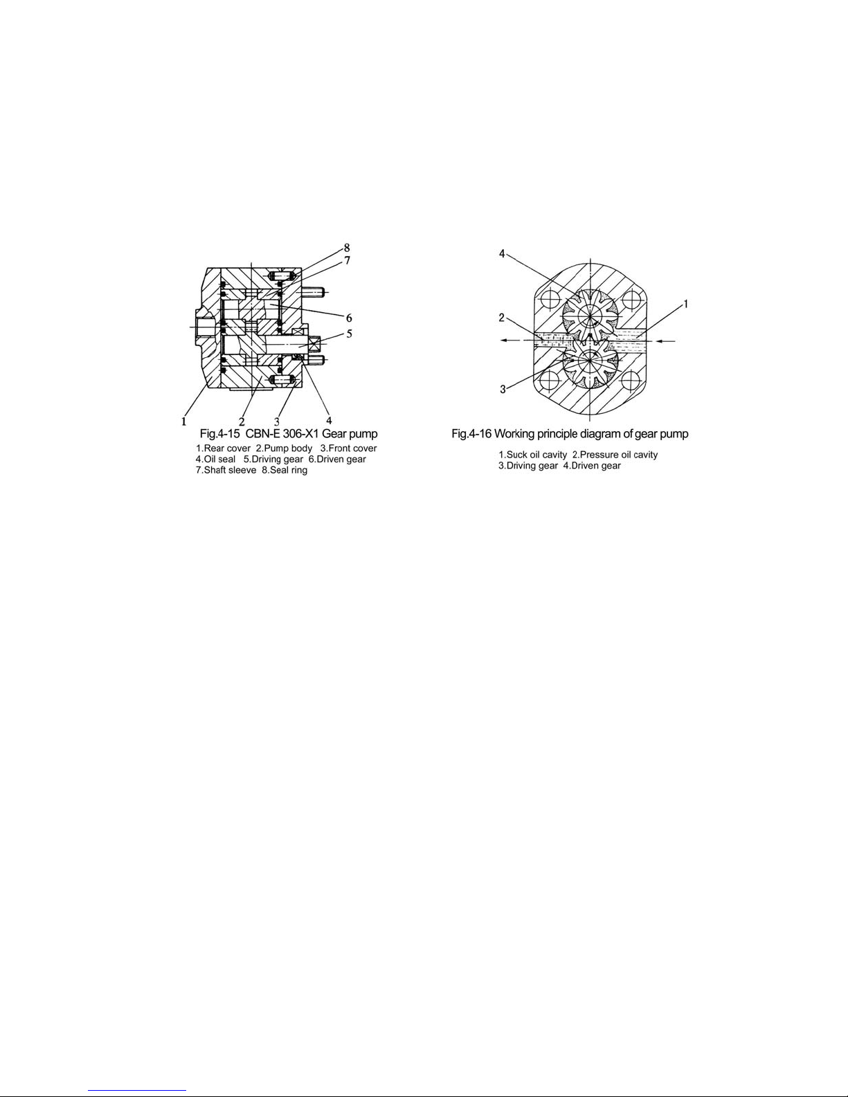
1) Working principle of gear pump
The gear pu mps atta ched to Agracat serie s tractor s are CB N model vo lume type outs ide
mesh gear pumps (Fig.4-15). They are all left handed pumps except the right hand ed pumps
on Ag racat-1 60, 164 tr ac tors. The gear pump s ar e mo unte d on the back e nd f ace of t he righ t
side of the gear ca se of the d iesel en gi ne front, w hich are driv en by engi ne s. The ge ar pump is
made up o f a p air of outsid e mesh sh aft gear (5) and ( 6), gear body (2 ), sleeve (7) an d rear
cover (1) and front cover (3).
The wo rking prin ciple of the gear pump is as Fig.4-16 . Take left -handed gear pum p as
example: After starting the engine, the driving gear of gear pump rotates counterclockwise,
and the oil enters the teeth from the pressure oil cavity and fill the teeth with oil. The oil
entered the pump is surrounded and contained by sleeve, meshed teeth and pump body and
two oil cavities which are not connected with each other are formed: suck oil cavity and
pressure oil cavity. The gear rotates right cavity (suck oil cavity) and the inner gear teeth
return mesh to make the volume be tween gear te eth increase and form part va ccum, and the
oil in the tank is sucked in . Meanwhil e the inner gear teeth of le ft cavity (pre ssure oil cavity)
begin to mesh (teeth int o each other) to sq ueeze the oil amon g the teeth out of the oil pum p.
Page 45

40
With the rotation of the engine, the oil in the cavity will continuously flow into the lifter
through gear pump.
During working, there is pressure difference between the suck oil cavity and pressure oil
cavity of the gea r pump, the hi gh pres sure oi l of pres sure oil cav i ty w ill leak an d return to th e
suck o il ca vi ty al ong th e clea ranc e of th e en d fac es of th e ge ar a nd s lee ve, g ear t ip and p ump
body a nd th e clearance formed by ba d ge ar mesh; which will cause p um p vo lume loss and the
heat of the hydraulic system. Too much volume loss will not make the gear pump form
normal working pressure; if seriously, the gear pump can't lift the implements.
In ord er t o red uce t he vo lume los s of the ge ar pump, co mple te flo ati ng sl eeve i s ad opted
in the pump, which has hydraulic automatic compensation and axial balance construction.
During working, the s leeve can fl oat in the pump body; the po sition of the sleeve is decided by
the force appli ed on the sleeve. The w idth of the pump body is 0.09 -0.18mm bigger than the
width sum of ge ar and sle eve. A fter mo unti ng , the front and rea r cove r are press ed ti ghtl y on
the pump body, the seal ring between the covers are compressed and the sleeve is pressed
tightly on the two end faces of the gear, thus not big clearance forms between sleeve and
covers. When the oi l pressu re in the ge ar r ises, the oil p ressure ap ply on th e b ack of the sle eve
throug h the cleara nce (Fig. 4-17), which ensures the good coo peration of the sle eve and gea r
stick end faces. This action is called hydraulic automatic compensation.
2) Lifter
A. Working principle of valve (simple direction exchange valve)
The str ucture a nd workin g principl e of the sim ple dire ction ex change val ve is as Fig.4-
19.
Main control valve (1) can be respectively put on lifting, neutral and lowering positions
throug h pu l li ng operati on handle (5). When main control valve (1) is on ne utral po si t io n (Fig- 4
-19b), the oil from the oil pump into the direction exchange valve flows back into oil tank
Page 46

41
through retu rning o il cavit y A a ccordi ng to the flo w di rection desi gnated by the arro w of the
Fig4-19(b). The n the e ntering oil cavity B and r et u rn ing oil ca vity C of the c ylinde r a re sea l ed
by main control valve (1); the oil cylinder is on seal and lock condition, and the implements
are mainta ine d in the fixe d po sition.
When the main control valve (1) is pushed to the lowering position (Fig.4-19d) from
neutra l pos ition , the re turning oil ca vity C is opene d, the oi l in th e cylin der is sq ueez ed back
into oil tank via returning oil cavity C under the action of the weight of the implement
acco rdin g to t he f lo w d ire ction de sig na ted by the arr ow in the Fi g.4- 19 d, t he n th e im plem ent
is l owering . In s uch ca se the oil f rom oi l pump i nto di rectio n exch ange v alve st ill fl ows b ack
into oil tank through return ing oil cavity A .
When the main control valve is pushed to lifting position from neutral position (Fig.419c), t he re turning oil cavit y A c loses , wh ile en terin g oi l cav ity B op ens. The n the oil from oi l
from oil p ump into di rec tion exch ange v alve ente rs t he oil c yli nder via oil ca vity B ac cord ing
to the flow direction designated by the arrow in Fig.4-19c, and push the piston forward, then
the implement begins to rise.
Syst em safet y valv e is adde d and establi shed i n the d irecti on exc hange v alve i n order to
prevent the hydraulic components from being damaged due to overload during the rising of
the implem en t.
Page 47

42
Page 48

43
B. Working principle of lifter
Fig.4- 20 is a wor king pr inciple di agram of pos ition adju sting of the l ifter (with simple
direction exchange valve and high adjustable performance). While pulling the operation
handle (1 0) to l owerin g positi on, po sitio n locati ng ste el ba ll (8) f alls in to lo wering the position
locatin g slot B o n p osition l ocating block (7), m ea nw h ile m a in con tro l valve (5) m o ves rig ht to
the lower p ositi on . The oil i n th e cylind er flow s bac k into oil tan k thr ough main co ntrol valv e
(5), and the implemen t begins to fal l down. Wit h the implem ent fall ing grad ually, sto p pin (2 )
fixed on the stop plate of the lift shaft and the lift shaft together rotate around the lift shaft
counterc lockwise, and sli p a long return push rod (4 ); after they slip to contact th e lowering
position limiting stop block (3) fixed on the r eturn pus h rod, th ey bring t he return p ush rod
(4) move right together; at the same time turn the operation handle until position locating
steel ball (8 ) is pushed out of the positio n locating sl ot B. In such case, un der the action of
Page 49

44
tension of retu rn sp ring (6) of the main contr ol valve, operatio n handl e (10) and main con trol
valve (5) jump back to th e ne ut ral p os itio n at the sam e ti me . A n d t he cy linder st op s re tu rn in g
oil, the impl ement also stop s falling. Thus, the falling of the imple ment depends on th e fixed
position of lowerin g return stop block (3) on re turn push ro d (4) i.e. t he closer t he cleara nce
between lowering return stop block and operation handle is the lower the implement falls.
Loosen the tightening bolt of lowering return stop block, the return push rod will lose the
ability t o make the op eration h andle return to n eutral po sition. And the main con trol valve
stops at lowering position from beginning to end, while the cylinder is in "floating" state all
the time.
While raising the implement, push operation handle (10) to lifting position and then
position locating steel ball falls into position locating slot A (Fig.4-20), main control valve (5)
moves left to lifting position. The implement begins to rise; with the implement rising
gradually, meanwhile, return stop pin (2) rotates around the lift shaft clockwise; when the
stop pi n slips to contact lifting r eturn sto p block (1 ), drive re turn pus h rod (4) to move lef t,
and at the same time ro tates operati on handle (10) until pu ll the loc ating steel ball (8) out of
its locating slot. In such case, under the action of the tension of ret urn spring (6), operation
handle (10) and main control valve (5) jump to neutra l position at the same time. And the oil
pump stops su pp lying oil to th e cylin de r, th e implem en t s tops rising. T h e raising h eig ht of th e
implement depends on the fixed position of the lift return stop block (1) on the return push
Page 50

45
rod (4). The closer the clearance between return stop block (1) and return push rod (4) is, the
higher the implement rises.
Notes:
During operation, if the adjustment is not suitable, it possibly makes the
operat ion handle can not return to its posi tion in time, and can cause parts damage due to
overload of hydraulic system.
C. Adju stment of hydraulic lifter
①
Adjustment of the utmost lifting position (Fig.4-21)
Set the co nt ro l le ve r (1 ) a t th e neutral po si tio n w h ich is ill us tra te d i n F ig .4- 21 . Rotate th e
lift arm assembly (2) upwa rd, until the cle arance between t he end of inner lift arm (3 ) and
stop p in (4) is no t less than 5m m (insert a s tee l pad thro ug h th e h ole ve nt pl ug (5 ), control t hi s
cleara nce b y th e pad thic knes s). A djus t the clea ranc e betw een stop bloc k (6 ) and stop pin (7 )
to be 9-10mm, then fix the stop block on the return push rod (8) with bolt and nut.
②
Adjustment of the lowering position
Set the control lever (1)
at the neutral position, rotate
the lift arm assembly (2)
downwards until the desired
lowering position arrives, and
adjust the clearance L
between stop block (3) and
stop pin (4) to be 9-10mm.
While in position adjusting,
adjustment should be done in
ploughing and forwarding; as the plough lowers into the soil and the required ploughing
Page 51

46
depth is reached, adjust the clearance between lowering stop block (3) and stop pin (4). After
adjustment, fix stop block (3) on return push rod (5) with bolt and nut, then raise the
implement several times to check the adjustment.
If the i mplement is provided with a supporting wheel, the floating control needs to be
used. Meanwhile, adjust lowering stop block (3) to the position where control lever1 (1) of
distributor (valve ) w ill not return to neut ral position.
③
Adjustment of lowering speed
During adjustment, the lowering speed of the implement can be adjusted through
rotating the adjusting valve bolt (5) (see Fig.4-18). When the lowering speed is suitably
adjusted, use check screw (4) to limit the moving range of adju sting valve b olt.
④
Adjust ment of safety valve
Safety valve has been adjusted before leaving the factory. In general, dismounting in
operation is not permitted anyhow. If the readjustment is necessary, it should be done on
special pr essur e test st and. The oi l for tes t is HC-8( SY1152 -77), the oil tem pera ture shou ld be
±℃
contro lled as 65 5 . Whe n the p ress screw plug of safety valv e is rota ted clo ckwise, th e
higher opening pressure is got, or vise versa .
In hydraulic system, as the precision of many parts is high, and the assembly parts have
been carefully tested and adjusted, cleanliness of the hydraulic oil, cleaning oil and the
enviro nment should be especially paid attention to during operation, maintenance and fixing
the breakdowns. Generally free dismount is not allowed.
Notes: Before s tarting the engi ne, mak e sure ther e is en ough o il in the l ifter h ousing, so
as to avoid damage to the hydraulic gear pump.
10. Use and adjustment of air brake device of trailer
Page 52

47
In order to e nsur e saf ety of the t railer t ranspo rtatio n of the tra ctor and a chiev e the aim
of prompt stop of the tractor and trailer, air brake system is mounted on the tractor. The
syst em is mad e up of ai r c omp resso r ( 1), recei ve r (5), br ake v al ve (4 ), a ir pr ess ure g aug e and
pipes (Fig.4-23).
1) Working process of air brake device of trailer
Air brake t railer is brake d through the compr essed air drivi ng the brake hung on the
trai le r wheels. Firs tly the compre s s e d air is co nveyed t o r eceiver from air com presso r throu g h
pipes, then i s conv eyed to t he br ake air chamber of the traile r wheel s thro ugh air -bleed ho le
(hole B in Fig.4-24) of the brake valve. When stepping on the brake pedal, through the
connecting rod (8 in Fig.4-23) driving the pull arm 10 of brake valve (Fig.4-24) to rotate
aroun d ax le pi n 13 to ma ke ad ju stin g b olt 12 p res s do wn b ra ke p ull r od 9, c omp ress ba lanc e
spring 7, push core rod 5, compress return spring 4, push valve seat assembly 3 aside
(compress valve seat spring 2), open high pressure air passage, and at this moment, the
compressed air of receiver, from hole A to valve seat hole, then to mouth of hole B and
continuously respectively enter the left and right brake air chambers of trailer wheels
throug h air-b leed pip e (7 in Fig .4-23) o f brake v alve and three-w ay pipe connector and push
the brake tappe ts of l eft and righ t bra ke s, an d thus achie ve brake of the trailer.
After c ompleting brake, lo osen foo t brake p edal, th e brake adju sting bo lt will r eturn t o
the initial position, and the brake tappets and core rod assembly will also return to their
initial position u nder the ef fort of compr essed return spring; th en the valve s eat assemb ly 3
will move right to contact the valve mouth on left housing 6 under the effort of compressed
Page 53

48
valve seat spring, and reseal the passage between receive and the left and right brake air
chamb er of the tr ailer. At th is moment t he waste gas (compress ed air) in l eft and righ t air
chamber will go int o the air th rough pipe s, hol e B of brake va lve, inner ho le of core rod and
inner hole C of tappets.(Fig.4-24).
2) Use and adjustment of air brake device of trailer
①
During working of air compressor, if the air pressure is too low, seal performance of
exhaust valve should be checked, and cleaned or ground if necessary. If the air compressor
has worked for 24 hours, and the oil gathered in the receiver is more than 15-20ml, the wear
condit ion of t he p i st on ring s of air compresso r shoul d be chec ke d, and it shou ld b e repla ced if
necess ary. The ai r compres sor should b e checked or b e filled wi th oil aft er every ten hours '
work.
②
Use an d maintenan ce of brake valve
Durin g u s in g if the air pressur e o f receiver drops to o f a st, and a ll t h e p ipe conn ec tors ar e
confirmed to have n o a ir leak , t hen scr ew o ut the val ve co ver con ne ctor 1 ( Fi g.4-24) , cl ean t h e
gathered dust on the surface of the rubber of valve seat assembly 3, and slightly grind the
compr essed print s on fi ne abr asive clo th if necess ary. Genera lly after 10 00 hou rs ' work of the
valve, should dismantle and clean all the parts, grind the valve seat, adjust the maximum
pressure of brake, and check the seal performance after assembling.
③
Adjust ment of brake pressure
When th e brak e peda ls are stepped i nto the lowest place, the maxi mum pre ssure o f the
air entered into the brake air chambers of trailer should be 0.45-0.5MPa. During adjustment,
connect an air pressure gauge in the p ipes which pass through brake air chamber, rotate the
adjust ing bo lt 12 to contact ta ppet 9 accordin g to Fig .4-24, t hen ste p on the pedals again t o
the lowest position, if the numerical value on the air pressure gauge is lower than 0.45Mpa,
then use nut to lock the limiting bolt tightly.
④
Adjustment of brake time
The brake time of trailer should be basically synchronous with the brake time of the
tractor, otherwis e it sh ou ld be rea d justed; adjust connecti ng ro d 8 (F ig. 4-2 3) to ad d i ts length ,
the brake time of trailer will advance; adjust connecting rod 8 and reduce its length, the
brake time of tra iler w ill exten d. Gen eral ly th e bra ke ti me of air br ake t rai ler shou ld be a bit
shorter than the brak e ti m e of tractor.
Page 54

49
Ⅴ
. Main Troubles of Tractors and Trouble Shooting
1. Engin e
1) Adjustment of du al stage clu tc h
2) Engine does not develop full power
Cause Remedies
1.Weath er col d
Pour hot wat e r into th e radiat o r or p reheat t h e oil
befor e pouring it in to crankcase
2.Fuel flow unsteady
Check and clean the fuel pipe line and filter
element
3.Air leaking into the fuel pipe line
Remove the air and tighten all fuel pipe
connections
4.Pump plunger and barrel ,
delivery valve and its seat ,nozzle
and its body sticking or da m aged
Repair or repla ce them
5.Loss of compre ssion pressure,
because of the inlet or exhaust
valve leaky ,no valve clea rance ,
cylinder head gasket damaged ,
piston rings gummed up or worn
nut
Lap inlet or exhaust v alve . Adjust the valve
clearance .Renew cyliner head gasket or piston
rings, if nec essary.
6.Shortage of the battery electricity Recharge or replace the battery
Cause Remedies
1.Air filt er or fu el f ilt er ch ok ed C lea n it in light fu el or kero sen e
2.Beginning of fuel delivery incorrect Adjust according to the recommended procedure
3.The fuel containing water Drain out the water deposit and change fuel
4.Nozzle needle sticking or holes
chocked
Repair or repla ce the noz zle unit
5.Inlet or exhaust valve leaking , or
valve clearance incorrect
Lap va lve or adjus t valve clearance
6.Main bearing o r con-rod bearing
worn badly or seized up
Repair or repla ce them
7.Poor uniformity of single cylinder
output
Calib rate the fuel delivery of injection pump and
the injection pressure of injector
Page 55

50
3) Engine does not develop full power
Check if the engine can be cranked by hand . I f not , the cause may be as follows.
A.Cranksh aft and bearing seize d up Repair or change th e m
B.Piston stick ing Re pa ir or cha nge pis ton cylin der liner
If the engine can be cranked freely , the causes may be as follows.
Cause Remedies
1.Oil not enough or broken off
Check if oil gallery is stopped up and if the oil in
crankcase is enough
2.Oil diluted or aged
Check if the oil has been diluted by the leakage
fuel from fuel pump plunger unit and if the oil is
aged. If so ,settle the problem
3.Sudden oil pump failure or oil
filter st opped up or relie f valve/bypass valve went wrong
Repair or change oil pump ,Clean or chan ge the
element
Cause Remedies
1.Engine overheated due to lack
of cooling water
Check regularly if the cooling water is enough
2.Cylinder overheated because of
water scale
Scour out the water jacket
3.Engine overloaded Follow the regulations of operation specified
4.Low tension of V-belt Adjust the tension or change the belt
Cause Remedies
1.Fuel consumed or fuel pipe cr ack Repla ce fuel or ch ange the pipe
2.Fuel containing air Remov e the air
3.Fuel filter or fuel pipe line
bloc ked up
Rinse the filter or the pipe
4.Plunger spring inside the injection
pump broken
Replace the spring with a new one
Page 56

51
4) Engine smoking abnormal
5) Engine overheat
2. Transmission system
1) Clutch slippage
Cause Remedies
1.Engine overloaded
Lighten the load . If the matching of engine and
driven unit is inadequate ,correct it .
2.Black smoking becasue of second
compres si o n rin g fitt ed inversely or
oil scraper ring worn out badly
Refit the ring or change the oil scraper ring.
3.While smoke because of fuel
containing water , bad atomization of
fuel and l ow injection pr essure
Ringse fuel tank and filter with filtered fuel.
Repair the nozzle assembly . Calibrate the
pressure
Cause Remedies
1.Low tension of v-belt Adjust the tensionor change the v -belt
2.Engine overh eated Lighten the load
3.High exhaust tempera ture because
of fuel delivery delayed or leakage of
fuel from injector
Repair the fuel delivery system
Cause Remedies
1.Fri ction disc surfaces stained with
oil
Clean the surface with diesel , and eliminate
leakage points
2.Clutch pressing springs weakened
or broken
Replace the spri ng
3.Too short free trav el or no free
travel of pedal , unid entical clearan ce
between release bearing and release
levers
Readjust pedal free travel according to
reqirements
4. Friction disc worn out or broken Replace friction disc
Page 57

52
2) Incomplete disengagement of clutch and difficult shifting
3) Abnormal noise in gearbox
℃
4) Gearbox overheat (oil temperature is more than 90 )
3. Transmission system
1) Ineffective brake
Cause Remedies
1.Excessive or too small free travel Readjust according to requirements
2.Unidentical clearance between 3
release levers an d release be aring
Readjust according to requirements
Cause Remedies
1.Excessive wea r or cracki ng of the
gear t eeth faces
Repla ce gea rs
2.Gear teeth breakage Replace gear
3.Bearing worn out excessively or
damaged
Repla ce bear in gs
4.Improper meshing backl ash of
main drive gears
Readjust it to required numerical valve
Cause Remedies
1.Too sm all bearing clear an ce or
meshing clearance of bevel gears
Readjust to required mumerical value
2.Lack of oil Fill lubrication oil to required level
3.Poor quality of oil Clean with diesel ,add required lubricating oil
Cause Remedies
1.Fr iction l inings worn out excessi v ely Repla c e f ri c tion lini n gs
2.Bra ke lining s stained with oil
Clean b rake linings with gasoline and re m ove oil
leakage point
3.Adjust improperly Readjust according to requ irements
Page 58

53
2) Riding di rection change with brakin g on both sides of driving whee l
3) Incomplete disengagement and generating heat
4. Steering gea r and walking system
1) Difficult steering
2) Difficult steering
Cause Remedies
1.Right and le ft brake pedal travel
different
Read just brake p edal travel
2.One side of br ake lining s stained oil
Flush the stain ed lining s with gas ol ine and
remove
3.We a r on right and left frict ion
linings unidentical
Adjust or replace friction linings
Cause Remedies
1.Return spring of brake shoes
weakened
Replace sp ring
2.Too small clearance between brake
linings and drum
Adjust pedal free trav el
Cause Remedies
1.Excessive clearance between crankpin
and worm or steering screw worm and
nut
Readjust the clearance or replace the worn parts
2.Low inflation pressure in front tires Inflate as specified
3. Insuffic ient oil supply of oi l pump Choose suitable oil pump or check the oil pump
4. Air in steering system Remove air and check suck oil pipe
5. Fuel tank is not full Fill to required level
Cause Remedies
1. Inflation pressure of right and left
tyres not identical
Inflate as specified
2. We ar of the treads on left and right
tyres not identical
Replace with new tyres
Page 59

54
3) Oscillation of the front wheels
4) Early worn out of front wheel tyres
5. Hydraul ic hitch system
1) Implemen ts not bein g able to lower or lift
2) Fast st ill faling of implements
Cause Remedies
1.Excessive clearance of tapered roller
bearing on front wheel or bearing worn
out
Readjust clearance or replace the bearing
2. Ball pins or joint seat worn out Replace ball joint or ball joint seat
3. Pend ulum shaft bush wor n out Replace b us h
4. Ste ering knuck le shaft bush wo rn out Replace shaft bu sh
Cause Remedies
1. Improper adju stment of front toe-in Readjust toe-in
2. Low inflation pressure of tyre Inflate tyre to specified pressure
3. Driving wheel mounted reversely Remount the driving wheel
Cause Remedies
Adjusting valve locked Loosen adjusting valve
Cause Remedies
1. Cylinder and piston worn out
Check and repair or replace cylinder and
piston
2. Upper oil seal of piston damaged Replace oil seal
3. Sliding valve of divider worn out Replace divider
Page 60

55
6. Trailer air brake system
1) Insufficient air pressur e
2) IInsufficient brake force, air pressure gauge pointer continuously falls
during brake,
continuous exhaust sounds at exhaust mouth
3) Brake si tuation not being able to be relieved after lo osening brake pedal
Cause Remedies
1. Air pump belt is too loose Adjust tightness of belt or replace belt
2. Pipe connectors leak
Check out the leak ing position and remove
breakdowns
3. Inlet and outlet valve of air compressor
not sealed and spring damaged
Grind valve sea t, rep la ce spring
4. Pis ton rings and cylinder lining of air
compressor seriously damaged
Replace piston rings and cyli nder lining
5. Filter blocked Clean filter
6. Safety valve is not completely closed or
is not flexible
Check and repair or replace safety valve
7. Cylinder head studs of air compressor is
loose or cylinder gasket leaks
Tightly screw cylinder head studs or replace
cylinder gasket
Cause Remedies
1. Impurity between brake valve core rod
end face and valve
Clean valve seat, re move impurity
2. Valve seat ground or damaged Repair or replace valve seat
Cause Remedies
1. Exhaust clearance too small or no
clearance
Adjus ting bolt wound out to inc rease
clearance, exhaust clearance should be
amon g 1.5-2mm
2. Bal ance spring not suitably mounted Remount balance spring
Page 61

56
7. Electrical system
1) Starter
2) Generator
Cause Remedies
1. Starter is out of running
⑴ Connecting wire broken or poor contact
of connecting wire
Weld or tigh ten the nuts on contacts
⑵ Low voltage of b attery Recharge or replace battery
⑶ Poor contact of b rush and commutator
Clean surface of commutator or replace
brush
⑷ Inner short or broken circ uit of starter Repair after checking
2. Starter can run idle , but fails to start
engine
⑴ Poor contact of brush and commutator Clean commutator contact face
⑵ Surfac e of com m utator burned out or
stained with oil dust
Repair it well with abrasive cloth or clean oil
dust out
⑶ Poor contact of connectors Clean or tightly screw contact point
⑷ Poor contact of solenoid switch Check and repair solenoid switch
⑸ Battery ins uf ficient or vo lta ge too low ⑸ Recharge battery after checking
3. Starter runs with star ting pinion
unmeshed and pinion s knocked at each
other. To o sm al l tr av el of armature
Screw the connecting screw of armature in
for 2-3 rings
Cause Remedies
1. Genera tor fails to generate current
⑴ Connec ting wire s l oose, broken, s hort
circu it or wrongly connected
Repair well after checking
⑵ Diode damaged, wires broken or have
short circuit
Replace it or re pair it
⑶ Winding of rotor or stator broken, have
short circuit or earthing
Repair or replace
⑷ Regulated voltage of regulator too low Adjust the voltage a bit higher
⑸ Regula tor termi nal burnt out or inside
wirin
g
connec t or broken
Check and repair
2. Ins ufficie nt output powe r o f generator
⑴ Coils of stator and rotor par t short
circuit or broken
Repair or replace
Page 62

57
Cause Remedies
⑵ Each or bot h of the diode dama ged Replace
⑶ Generator belt too loose Adjust to tighten belt
3. Unsteady current
⑴ Generator belt slips Remove o il dust or adjus t belt tension
⑵ Poor contact of recharged c ircuit Check and remov e
⑶ Coil of stator and rotor will be in short
circuit or broken circuit
Repair or replace
⑷ Breakdowns of regulator Repair or replace
4. Abnormal noise of generator
⑴ Improper mount of generator,
inter ference between rotating part and
fixing part
Find out interference,adj ust mounting
position
⑵ Bearing damaged Repl ace bear ing
⑶ Rotor knocking against stator Repair
5. Bu rnt smell of generator
⑴ Damaged diode cause one fase or two
fases burnt
Replace
⑵ Stator knocking against rotor core and
burned and cause sho rt circuit of winding
of stat or an d rotor coil
Repair or replace coil
⑶ Ineffective regulator or too high of
regula ted voltag e, overloa de d for a long
time
Repla ce or ad j u st
6.Charged curr ent too big
⑴ Inner short circuit of single grille of
battery
Replace
⑵ Too hi gh regulated voltage of regulator Adjust lower
⑶ Poor earthing of regu lator Check and repair
⑷ Regulator terminal ineffective and dirty Repair and clean
Page 63

58
3) Battery
Cause Remedies
1. Frequentl y insufficient electric power
⑴ Breakdowns of generator or regulator
or no charging electric current
Repair generator or regulator
⑵ Loosened connecting wires of charging
circuit or rust making resistance increase
⑵ Check to see whether terminals and bolts
of connecting wires are loose or not and
tighten them, or remove rust
⑶ Shor t circuit o f plate ⑶ Check and repair
2. Automatically discharging of battery,
too high impurity content of plate material
or impure electrolyt e
2. Completely discharge battery or
overdischarge battery to make plate
impurity enter electrolyte then pour
electrolyte out and clean with distilled water,
and r efill with new electrolyte and re charge
3. Charge capacity of battery distinctiv ely
reduces (low discharging volt age, high
charging voltage, low indensity of
elect rolyte and pl ates sulphuri zed)
⑴ Frequently insufficient electric power
⑴ Charge for a long time with small electric
current or compl etely charge and completely
discharge repeatedly
⑵ Discharge in small electric current for a
long time and not charging in time
⑵ Make activated material restore. Or
charge with sulphre removal method
⑶ Too low of electrolyte lever, upper part
of pla te emerging from electrolyte lever
⑶ Replenish electrolyte
Page 64

59
Ⅵ
Chapter Appendix
1. Wiring diagram of the electrical system
2. Accessories for customers to order
Customers may order and purchase the following accessories of the tractors from our
factory according to requirements:
Page 65

60
Serial No. Name Quantity Purpose
1 High-lugged tyres One pair Used in paddy field
2 Turf tyres Two pairs For garden use
3 Cab 1 Improve driver's working condition
4 Protective roll bar 1 Ensure safety of drivers
5 Belt pulley 1 For fixed operation
Page 66

61
3. Distribution diagram of rolling bearing and
transmission system of Jm series tractors
Page 67

62
Page 68

63
4. Specifications and distributions of oil seals in JM series tractors' chassis
Parts Specifications positions
Qt
y.
JB2600-80
Oil seal
××PD35 55 8
××SD35 55 10
××PD50 72
12
××PD50 80
12
××PD55 75
12
Front end of 1st shaft
Inside bearing cover of PTO shaft
Outer of driving shaft bushing
Outer of bearing seat of final transmission
shaft
Inner side of driving shaft bushing
1
1
4
4
2
GB3452.1-82
O-ring
×11.8 1.8
×15 2.65
×15 2.65
×22.4 2.65
×28 3.55
×67 3.55
×103 3.55
×112 3.55
PTO shifting fork shaft
Sub-transmission shifting lever
Shifting fork shaft of differential lock
Outer of reverse shaft
Driving gear shaft of final transmission
Front bearing seat of 2nd shaft
Out ring of bearing seat
Inner of driving shaft bushing
1
2
1
1
2
1
2
2
GB3452.1-82
O-ring
×9.5 2.65
×10 2.65
×11.2 2.65
Creeper shifting fork shaft
Power shifting fork shaft of transfer box
Creeper shifting lever
1
1
2
JB2600-80
Oil seal
GB9877.1
××SG25 40 8
××FB25 47 7
Oil seal seat of transfer box
Oil seal seat of Agracat-254 transfer box
2
1
GB3452.1-82
O-ring
×15 2.65
×58 3.55
×54.5 3.55
Idle shaft
Oil seal seat of transfer box
Front fixing seat
1
1
1
JB2600-80
Oil seal
GB3452.1-82
O-ring
××SD35 55 12
×19 2.65
Support frame of release bearing seat
Main clutch shaft
1
2
GB3452.1-82
O-ring
×15 2.65 Brake camshaft 2
Transmission box
Creeper
Transfer box
Dual stage clutch
Brake
Page 69

64
Parts Specifications positions
Qt
y.
Non-standard
oil seal of
standing shaft
Non-standard
oil seal of
standing shaft
××40 48 6.5
××38 62 11.5
Lower part of steering kunckle of front axle
Inner end of front wheel hub
2
2
GB3452.1-82
O-ring ×30 3.55
Upper part of left end right steering
kunckle
Two ends of pendulum shaft
2
2
JB2600-80
Oil seal
××SD35 56 12
××W50 72 7
××W50 72 7
××W50 72 12
××W50 72 12
Bearing seat of driving bevel gear
Left,right side reduction housing
Driving shaft
Left, right side reduction housing
Driving shaft
2
2
2
2
2
GB3452.1-82
O-ring
×21.2 3.55
×28 3.55
×34.5 3.55
×63 3.55
×69 3.55
×77.5 3.55
×82.5 3.55
Driving bevel gear
Inner of front pendulum shaft
Upper bearing cover
Middle of front pendulum shaft
Back support seat assy
Inner of bearing seat of driving bevel gear
Middle of bearing seat of driving bevel gear
1
1
2
1
1
1
1
JB2600-80
Oil seal
××PD30 45 8 Outer of steering rock arm shaft 1
GB3452.1-82
O-ring
×11.8 2.65 Adjusting bolt 1
GB3452.1-82
O-ring
×31.5 3.55 outside of fuel delivery flange 1
Front axle
Front drive axle
Steering gear
Fuel tank
Page 70

65
5. Sizes of hitch system
Note:* are adjustable sizes
Parts Specifications positions Qty.
Lifte
r
JB2600-80
Oil seal
××SG42 62 10 Outside of lift shaft
2
GB3452.1-82
O-ring
×91.8
×13.2 2.65
×13.2 2.65
×17 2.65
×19 2.65
Inside of oil drain plug
Joint of distributor and lifter
Outside of pressing screw plug of lifter
Adjusting valve spool rod
Joint of distributor and lifter
1
2
1
1
1
GB3452.1-82
O-ring
×63 5.7
×63 5.7
Outside of piston
Inside of cylinder head
1
1
GB3452.1-82
O-ring
×92.65
×92.65
×15 2.65
Safety valve seat
Inside of distributor handle shaft
Lower of pressing screw plug of distributor
1
1
1
Model
Parameter
JM200 JM204 JM250, JM254
H 690 705 702 702
H
1
200 146 180 180
h 470 470 495 495
R 497.5 497.5 525 525
R
1
545 600 625 625
R
*
2
478 533 558 558
R
3
250 268.5 280 280
R
*
4
446 453 475 475
R
5
130 190 196 196
B 520 546 718 718
δ °16 °13.5 ° 10.5 ° 10.5
Page 71

66
Page 72

67
6. OECD approval No. of JM series tractors
OECD approval No. of tractors to which the protective structure are fitted
Model JM-180 JM-200 JM-204 JM-254
OECD
Approval No.
(Full code)
1354 1563 1657 1650
Model OECD approval number
JM-180 NT/ROPS - R/S0110/4
JM-184 NT/ROPS - R/S0110/3
JM-200 NT/ROPS - R/S0110/2
JM-204 NT/ROPS - R/S0110/1
Page 73

MAHINDRA YUEDA (YANCHENG) TRACTOR CO.,LTD.
Add. : 90# South Wengang Road Yancheng City, Jiangsu Province
:
Tel 0086-515-88231130/88231131
:
Fax 0086-515-88229791
:
Postcode 224002
:
Tttp //www.jm-tractor.com
:
E-mail tractorobd@yantuo.cn
 Loading...