

Page 1
Page 2

Page 3
OPERATOR’S MANUAL
6065/6075 2WD / 4WD
TIER-4 FINAL
CALIFORNIA
Proposition 65 Warning
Diesel engine exhaust and some of its constituents are
known to the State of California to cause cancer,
6065 / 6075 2WD & 4WD Rev-00
birth defects and other reproductive harm.
If this product contains a gasoline engine:
The engine exhaust from this product contains chemicals
known to the State of California to cause cancer,
birth defects or other reproductive harm.
The state of California requires the above two warnings.
Page 4

Contents
Emission Control Warranty for California................ 5
Emission Control Warranty for Federal ................... 9
About This Manual ................................................ 13
Introduction............................................................ 14
Tractor ............................................................. 14
T
ractor Serial Number .....................................15
General Description ................................................ 16
Owner Assistance ................................................... 17
Owner’s Personal Data........................................... 18
Roll Over Protective Structure (ROPS) ................... 19
Safety Instructions.................................................. 20
Safety Signs ............................................................ 25
Universal Symbols .................................................. 29
LH & RH View of Engine ....................................... 30
Lamps .................................................................. 31
Controls, Instruments & Operations ...................... 32
Instrument Cluster ................................................. 33
Turn Indicator ..................................................
4WD Indicator ................................................. 34
Gear Neutral Indicator .................................... 34
High Beam Indicator ....................................... 34
Clutch Over Ride Indicator ............................. 34
Air Filter Clog Indicator .................................. 34
High Temperature Warning Indicator ............. 34
Check Engine Indicator ................................... 34
Battery Charging Indicator .............................. 34
Low Oil Pressure Indicator .............................. 35
Parking Brake Indicator ................................... 35
MIL Indicator ................................................... 35
PTO Indicator .................................................. 35
Water In Fuel Indicator ................................... 35
Heater Indicator .............................................. 35
Service Reminder Indicator ............................. 35
Beeper Output Provision ................................. 35
RPM Meter ...................................................... 36
Hour Counter .................................................. 36
Trip Hour Counter ........................................... 36
Trip Hour Reset Switch ................................... 36
Fuel Gauge ...................................................... 37
Coolant Temperature Gauge ........................... 37
34
Switches ................................................................. 38
Ignition Key Switch
Steering Column Mounted Combination Switch
Light Switch .............................................. 38
Dipper Switch
Turn Signal Switch .................................... 38
Horn .......................................................... 38
Plough Lamp Switch ....................................... 39
Hazard Switch ................................................. 39
Neutral Safety switch ...................................... 39
Brake Switch ................................................... 39
Forward Reverse Switch .................................. 39
PTO AUTO / MANUAL Switch .......................... 40
PTO ON/OFF Switch ........................................ 40
Seven Pole Socket ........................................... 41
Mobile Charger Socket ................................... 41
Fuse Box .......................................................... 41
Controls ..................................................................42
Operator Seat ..................................................
Adjusting Seat Position ................................... 43
Weight Adjustment ......................................... 43
Tilt Adjustment................................................ 43
Using Seat Belt................................................ 43
Fasten Seat Belt .............................................. 43
Release Seat Belt ............................................. 43
Tilt Steering ..................................................... 43
Tilt Adjustment................................................ 43
Hand Throttle Operation ................................. 44
Increasing Engine Speed ................................. 44
Engine Tachometer Speeds ............................. 44
Decreasing Engine Speed ................................ 44
Constant Speed Setting .................................. 44
Foot Throttle Operation .................................. 44
4WD Engagement Lever ................................. 44
Brake ............................................................... 45
Parking Brake .................................................. 45
Differential Lock Pedal .................................... 46
Clutch Pedal .................................................... 46
PTO ..................................................................47
Range Shift Lever ............................................ 48
......................................... 38
... 38
............................................ 38
43
6065 / 6075 2WD & 4WD Rev-00
Page 5

Contents
F-R Shuttle Shift Lever .................................... 49
Speed Shift Lever ............................................ 49
Auxiliary Valve ................................................. 49
Opening the Hood .......................................... 50
Closing the Hood ............................................ 50
Hydraulic System & Operation .............................. 51
Position Control - Operation ................................. 49
Quadrant Assembly .........................................
Position Control .............................................. 52
Position Control Lever Setting ........................52
Draft Control - Operation ...................................... 53
Draft Control ...................................................
Setting the Draft Control................................ 53
Three Point Linkage ............................................... 54
Top Link ........................................................... 54
Draft Sensing Bracket
Telescopic Lower Links .................................... 54
Adjustable Lift Rods ........................................ 55
Stabilizers ........................................................ 55
Attachments ...........................................................56
Swinging Drawbar ..........................................
Using Swinging Drawbar ................................ 56
Attaching PTO Driven Implement ................... 56
Jerrycan Weights ............................................. 57
Wheel Tread Adjustment ................................ 57
Pneumatic Tires ...................................................... 58
Adding Liquid W
Inflation ...........................................................58
Exceptions (Rear Tires only) ............................ 58
Care of Tires .................................................... 59
Shipping Tractors Equipped with ................... 59
Pneumatic Tires
Tire Protection during Storage ....................... 59
Mounting Tires on the Rim ............................ 59
Operating Instructions ........................................... 60
Before Starting The Tractor
Starting the Tractor......................................... 60
Stopping the Engine ....................................... 60
Cold Starting Aid ............................................ 61
Glow Plug........................................................ 61
Driving the Tractor .......................................... 61
6065 / 6075 2WD & 4WD Rev-00
..................................... 54
eight ..................................... 58
............................ 60
52
53
56
Tractor Storage ................................................ 62
Long-Term Tractor Storage .............................. 62
Using the Tractor After Storage ..................... 62
Precautions .............................................................63
Cleaning the Tractor .......................................
Using High Pressure Washers ......................... 63
Operating the Tractor ..................................... 64
The Tractor ...................................................... 65
Driving the Tractor .......................................... 65
Servicing the Tractor ....................................... 65
Operating the PTO (Power Take Off).............. 66
ROPS ................................................................ 66
Transporting Tractor on a Trailer .................... 66
Towing ............................................................. 66
Diesel Fuel ....................................................... 66
Do’s & Dont’s ........................................................67
Maintenance ........................................................... 70
Cooling System ...............................................
Radiator ...........................................................70
Radiator Cap ................................................... 70
Surge Tank ....................................................... 70
Thermostat ...................................................... 70
Cooling System ...................................................... 71
Water Pump ....................................................
Hose Connections ........................................... 71
Fan & Fan Belts ............................................... 71
Belt Adjustment .............................................. 71
Belt Removal ................................................... 71
Belt Replacement ............................................ 71
Draining the System ....................................... 72
Cleaning out Dirt and Sludge ........................ 72
Adding Coolant to the System ....................... 72
Cooling System Protection .............................. 72
Thresh Guard................................................... 73
Air Intake System ................................................... 74
Air Cleaner ......................................................
Body Air-Cleaner.............................................. 74
Cyclopack or built-in Pre-Cleaner ................... 74
Paper Element Filter ........................................ 74
Safety Cartridge .............................................. 74
Dust Collector Bowl ........................................ 74
Hose and Clamps ............................................ 74
63
70
71
74
Page 6

Contents
Emission Control System (ECS) .............................. 75
Emission Control System (EC
Positive Crankcase Ventilation (PCV) System .. 76
Removing the Oil Separator ........................... 76
Assembly the Oil Separator ............................ 76
Exhaust Gas Recirculation (EGR) System ........ 77
Diesel Oxidation Catalyst (DOC) ..................... 78
Under-Hood Muffler (UHM) ............................ 78
Fuel System ............................................................ 79
Clean Diesel F
Bleeding the Fuel Filter ................................... 79
Bleeding the Fuel Injection Pump .................. 79
Fuel Tank and Fuel Pipes ................................ 79
Tamper Proofing .............................................. 79
Fuel Filter......................................................... 80
Servicing the Fuel Filter .................................. 80
Lubrication System ................................................. 81
Oil Level Check ................................................
Oil Change ...................................................... 81
Engine Oil Filter .............................................. 81
Changing Spin On Filter ................................. 81
Turbocharger ................................................... 81
Electrical System .................................................... 82
Battery Maintenance Cleaning
Servicing .......................................................... 82
Effect of Low Temperatures ............................ 82
Alternator ........................................................ 82
Charging Circuit .............................................. 83
Starter Motor Removal ................................... 83
Front Axle & Power Steering (2WD)...................... 84
Front Axle - Front Wheel "Toe-in" Check ........ 84
Tips for maintaining the power steering system
Front Axle (4WD) ................................................... 85
Axle Oil Change ..............................................
Reduction Gear Oil Change ............................ 85
Front Axle - Front Wheel "Toe-in" Check ........ 85
Hydraulic & Transmission ....................................... 86
Adding Hydraulic and Transmission Oil
Hydraulic and Transmission Suction Oil Filter
Hydraulic and Transmission Strainer ............... 87
uel ............................................. 79
S) ....................... 75
81
........................ 82
.. 84
85
.......... 86
....... 86
Transmission Oil Drain .................................... 87
Check & Adjust Brake Pedal Free Play .................. 87
Head Lamp Adjustment ......................................... 88
Aiming Head Lamps............................................... 89
Lubricants ...............................................................90
General ............................................................90
Lubricant Storage
Alternate and Synthetic Lubricants ................ 90
Diesel Engine Lubricating Oil .......................... 90
Mixing of Lubricants ....................................... 90
Engine Oil ........................................................ 91
Selecting the Viscosity of Engine Oil (EO) ..... 91
Transmission, Hydraulics ................................. 92
& Steering Oil (GL)
Chassis Lubricant (CL) ..................................... 92
Front Axle ........................................................ 92
Oil Specifications Chart ................................... 92
Special Bolt Torques ............................................... 93
Specifications - 6065 2WD .................................... 94
Specifications - 6065 4WD .................................... 96
Specifications - 6075 2WD .................................... 98
Trouble Shooting .................................................. 100
Precautions for CRDI Engines
Engine ........................................................... 101
Turbocharger ................................................. 105
Hydraulics ......................................................105
Brakes ............................................................106
Transmission .................................................. 106
Rear Wheels .................................................. 106
Electricals ....................................................... 106
Power Steering .............................................. 107
Tractor History Card .............................................108
Service Record ...................................................... 109
Part Replacement Record ..................................... 110
Daily Operating Log ............................................. 111
Tractor Storage Precautions ................................. 112
Lubrication & Greasing Chart .............................. 113
Routine Service Schedule ..................................... 114
............................................ 90
....................... 100
6065 / 6075 2WD & 4WD Rev-00
Page 7

Emission Control Warranty for California
Product Warranty
Product warranty is provided as part of Mahindra &
Mahindra Limited support program for customers
who operate and maintain their equipment as
described in this manual.
Engine related warranties stated in this manual refer
only to emissions-related parts and components of
your engine. The complete engine warranty, less
emission-related parts and components, is provided
separately as the Limited Warranty for New Mahindra
& Mahindra Limited Commercial & Consumer
Equipment.
Mahindra & Mahindra Limited And California
Emission Control System Warranty (heavy duty offroad Compression ignition engines)
Your Warranty Rights and Obligations
The California Air Resources Board (CARB) and
Mahindra & Mahindra Limited are pleased to explain
the emission control system warranty on your heavy
duty off-road compression ignition engine. In
California, new heavy-duty off road compression
ignition engines must be designed, built and
equipped to meet the State’s stringent anti-smog
standards. Mahindra & Mahindra Limited must
warrant the emission control system on your heavy
duty off-road compression ignition engine for the
periods of time listed below provided there has been
no abuse, neglect or improper maintenance of your
engine.
Your emission control system may include parts such
as the fuel-injection system and the air induction
system. Also included may be hoses, belts, connectors
and other emission-related assemblies.
Where a warrantable condition exists, Mahindra &
Mahindra Limited will repair your heavy duty off-road
compression ignition engine at no cost to you
including diagnosis, parts and labor.
Mahindra & Mahindra Limited Emission Control
System Warranty Coverage
In California, heavy duty off-road compression
ignition engine emissions control-related parts are
warranted by Mahindra & Mahindra Limited for five
years or 3000 hours of operation, whichever occurs
first. If any emission related part on your engine is
defective, the part will be repaired or replaced by
Mahindra & Mahindra Limited.
Owner’s Warranty Responsibilities
As the heavy duty off-road compression ignition
engine owner, you are responsible for the
performance of the required maintenance listed in
your owner’s manual. Mahindra & Mahindra Limited
recommends that you retain all receipts covering
maintenance on your heavy duty off-road engine, but
Mahindra & Mahindra Limited cannot deny warranty
solely for lack of receipts or for your failure to ensure
the performance of all scheduled maintenance.
As the heavy duty off-road engine owner, you should
however be aware that Mahindra & Mahindra Limited
may deny you warranty coverage if your heavy duty
off-road engine or a part has failed due to abuse,
neglect, improper maintenance or unapproved
modifications.
Your engine is designed to operate on Diesel fuel only.
Use of any other fuel may result in your engine no
longer operating in compliance with California’s
emissions requirements.
You are responsible for initiating the warranty
process. The CARB suggests that you present your
heavy duty off-road engine to an authorized
Mahindra & Mahindra Limited Commercial and
Consumer Equipment Dealer / Retailer as soon as a
problem exists. The warranty repairs should be
completed in a reasonable amount of time, not to
exceed 30 days.
“If you have any question regarding your warranty
rights and responsibilities, you should contact
Mahindra, USA Inc at 1-877-449-7771.
Length of Warranty Coverage
Mahindra & Mahindra Limited warrants to the initial
owner and each subsequent purchaser that the heavy
duty off-road compression ignition engine is:
• Designed, built and equipped so as to conform
with all applicable regulations adopted by the
California Air Resources Board (CARB) pursuant to
its authority in Chapters 1 and 2, Part, Division 26
of the Health and Safety Code; and
• Free from defects in materials and workmanship
which can cause the failure of a warranted part to
be identical in all material respects to the part as
described in the application of Mahindra &
Mahindra Limited for certification for a period of
five years or 3000 hours of operation, whichever
occurs first, after the engine is delivered to the
initial retail purchaser. Mahindra & Mahindra
Limited is liable for damages to other engine
components caused by the failure of a warranted
part during the warranty period. If any emission
related part on your engine is defective, the part
will be repaired or replaced by Mahindra &
Mahindra Limited.
Warranted Parts
Coverage under this warranty extends only to the
parts listed (the emission control system parts) to the
extent these parts were present on the engine
purchased.
6065 / 6075 2WD & 4WD Rev-00
5
Page 8

Emission Control Warranty for California
Fuel Metering System:
• Fuel Pump
• Rail
• Injector
Air Induction System:
• Mixing Elbow
• Intake Manifold
• Turbocharger
• Charge Air Cooler
Exhaust Gas Recirculation (EGR) System:
• EGR valve
Positive Crankcase Ventilation (PCV) System
Miscellaneous Items Used in Above Systems:
• Electronic Control Unit
• Hoses, connectors, assemblies, clamps, fittings,
tubing, sealing gaskets and mounting hardware
Since emission related parts may vary slightly from
model to model, certain models may not contain all
of these parts and certain models may contain
functionally equivalent parts.
Warranty Service and Charges
Warranty service shall be provided during customary
business hours at any authorized Mahindra &
Mahindra Limited Commercial and Consumer
Equipment Retailer. Repair or replacement of any
warranted part will be performed at no charge to the
owner, including diagnostic labor which leads to the
determination that a warranted part is defective, if
the diagnostic work is performed at an authorized
Mahindra & Mahindra Limited Commercial and
Consumer Equipment Retailer. Any parts replaced
under this warranty shall become the property of
Mahindra & Mahindra Limited.
Maintenance Warranty Coverage
a) Any warranted part which is not scheduled for
replacement as required maintenance shall be
warranted for the warranty period defined in
subsection “Length of Warranty Coverage.” If any
such part fails during the period of warranty
coverage, it shall be repaired or replaced by
Mahindra & Mahindra Limited. Any such part
repaired or replaced under the warranty shall be
warranted for the remaining warranty period.
b) Any warranted part which is scheduled only for
regular inspection shall be warranted for the
warranty period defined in subsection “Length of
Warranty Coverage” to the effect of “repair or
replace as necessary” shall not reduce the period
of warranty coverage. Any such part repaired or
replaced under the warranty shall be warranted
for the remaining warranty period.
c) Any warranted part which is scheduled for
replacement as required maintenance shall be
warranted for the period of time prior to the first
scheduled replacement point for that part. If the
part fails prior to the first scheduled replacement,
the part shall be repaired or replaced by Mahindra
& Mahindra Limited. Any such part repaired or
replaced under the warranty shall be warranted
for the remainder of the period prior to the first
scheduled replacement point for that part.
d) Repair or replacement of any warranted part
under the warranty provision of this statement
shall be performed at no charge to the owner at
an authorized Mahindra & Mahindra Limited
warranty station.
e) Notwithstanding the provisions of subsection “d”
above, warranty services or repairs shall be
provided at all authorized Mahindra & Mahindra
Limited Commercial and Consumer Equipment
Retailer and distribution centers that are
franchised to service the subject engines.
f) The owner shall not be charged for diagnostic
labor that leads to the determination that a
warranted part is in fact defective, provided that
such diagnostic work is performed at an
authorized Mahindra & Mahindra Limited
warranty station.
g) Mahindra & Mahindra Limited shall be liable for
damages to other engine components proximately
caused by a failure under warranty of any
warranted part.
h) Throughout the engine’s warranty period defined
in subsection “Length of Warranty Coverage”,
Mahindra & Mahindra Limited shall maintain a
supply of warranted parts sufficient to meet the
expected demand for such parts.
i) Any replacement part may be used in the
performance of any maintenance or repairs and
must be provided without charge to the owner. It
is not necessary for replacement parts to be the
same brand or by the same manufacturer as the
original part sold with the engine. Such use shall
not reduce the warranty obligations of Mahindra
& Mahindra Limited.
6
6065 / 6075 2WD & 4WD Rev-00
Page 9

Emission Control Warranty for California
j) Add-on or modified parts may not be used. Such
use shall be grounds for disallowing a warranty
claim made in accordance with this warranty
statement shall not be liable under this article to
warrant failures of warranted parts caused by the
use of such an add-on or modified part.
k) The Executive Officer may request and in such
case, Mahindra & Mahindra Limited shall provide,
any documents which describe warranty
procedures or policies of Mahindra & Mahindra
Limited.
Consequential Warranty Coverage
Warranty coverage shall extend to the failure of any
engine components caused by the failure of any
warranted part still under warranty.
Limitations
This Emission Control System Warranty shall NOT
cover any of the following:
a) Repair or replacement required as a result of (i)
misuse or neglect, (ii) improper maintenance or
unapproved modifications, (iii) repairs improperly
performed or replacements improperly installed,
(iv) use of replacement parts or accessories not
conforming to Mahindra & Mahindra Limited
specifications which adversely affect performance
and/or durability, (v) alterations or modifications
not recommended or approved in writing by
Mahindra & Mahindra Limited.
b) Replacement parts, other services and
adjustments necessary for normal maintenance.
Limited Liability
a) The liability of Mahindra & Mahindra Limited
under this Emission Control System Warranty is
limited solely to the remedying of defects in
materials or workmanship. This warranty does not
cover inconvenience or loss of use of the heavy
duty off-road compression ignition engine or
transportation of the engine to or from the
Mahindra & Mahindra Limited Commercial and
Consumer Equipment Retailer. Mahindra &
Mahindra Limited SHALL NOT BE LIABLE FOR ANY
OTHER EXPENSE, LOSS, OR DAMAGE, WHETHER
DIRECT, INCIDENTAL, CONSEQUENTIAL (EXCEPT AS
LISTED ABOVE UNDER “COVERAGE”) OR
EXEMPLARY ARISING IN CONNECTION WITH THE
SALE OR USE OF OR INABILITY TO USE THE HEAVY
DUTY OFF-ROAD COMPRESSION IGNITION ENGINE
FOR ANY OTHER PURPOSE.
b) NO EXPRESS EMISSION CONTROL SYSTEM
WARRANTY IS GIVEN BY Mahindra & Mahindra
Limited WITH RESPECT TO THE ENGINE EXCEPT AS
SPECIFICALLY SET FORTH IN THIS DOCUMENT. ANY
EMISSION CONTROL SYSTEM WARRANTY IMPLIED
BY LAW, INCLUDING ANY WARRANTY OF
MERCHANTABILITY OR FITNESS FOR A PARTICULAR
PURPOSE, IS EXPRESSLY LIMITED TO THE
EMISSION CONTROL SYSTEM WARRANTY TERMS
SET FORTH IN THIS DOCUMENT.
c) No dealer is authorized to modify this California
and Mahindra & Mahindra Limited Emission
Control System Warranty.
c) Transportation to and from the Mahindra &
Mahindra Limited Commercial and Consumer
Equipment Retailer, or service calls made by the
Retailer.
6065 / 6075 2WD & 4WD Rev-00
7
Page 10

6065 / 6075 2WD & 4WD Rev-00
Page 11

Emission Control Warranty for Federal
Product Warranty
Product warranty is provided as part of Mahindra &
Mahindra Limited support program for customers
who operate and maintain their equipment as
described in this manual.
Engine related warranties stated in this manual refer
only to emissions-related parts and components of
your engine. The complete engine warranty, less
emission-related parts and components, is provided
separately as the Limited Warranty for New Mahindra
& Mahindra Limited Commercial & Consumer
Equipment.
Mahindra & Mahindra Limited, Federal Emission
Control System Warranty (Non-Road Diesel)
Your Warranty Rights and Obligations
The United States Environmental Protection Agency
(EPA) and Mahindra & Mahindra Limited are pleased
to explain the emission control system warranty on
your non-road diesel equipment engines must be
designed, built and equipped to meet the U.S. EPA
regulations for non-road diesel engines. Mahindra &
Mahindra Limited must warrant the emission control
system on your non-road diesel equipment engine for
the periods of time listed below provided there has
been no abuse, neglect or improper maintenance of
your non-road diesel equipment engine.
Your emission control system may include parts such
as the fuel-injection system and the air induction
system. Also included may be connectors and other
emission related assemblies.
Where a warrantable condition exists, Mahindra &
Mahindra Limited will repair your non-road diesel
equipment engine at no cost to you including
diagnosis, parts and labor.
Mahindra & Mahindra Limited Emission Control
System Warranty Coverage
Your non-road diesel equipment engine emissions
control-related parts are warranted by Mahindra &
Mahindra Limited for five years or 3000 hours of
operation, whichever occurs first. If any emission
related part on your engine is defective, the part will
be repaired or replaced by Mahindra & Mahindra
Limited.
Owner’s Warranty Responsibilities
As the non-road diesel equipment engine owner, you
are responsible for the performance of the required
maintenance listed in your owner’s manual. Mahindra
& Mahindra Limited recommends that you retain all
receipts covering maintenance on your non-road
diesel equipment engine, but Mahindra & Mahindra
Limited cannot deny warranty solely for lack of
receipts or for your failure to ensure all scheduled
maintenance is performed.
6065 / 6075 2WD & 4WD Rev-00
As the non-road diesel equipment engine owner, you
should however be aware that Mahindra & Mahindra
Limited may deny you warranty coverage if your nonroad diesel equipment engine or a part has failed due
to abuse, neglect, improper maintenance or
unapproved modifications.
You are responsible for presenting your non-road
diesel equipment engine to an authorized Mahindra &
Mahindra Limited Commercial and Consumer
Equipment Retailer as soon as a problem exists. The
warranty repairs should be completed in a reasonable
amount of time, not to exceed 30 days.
“If you have any question regarding your warranty
rights and responsibilities, you should contact
(Mahindra, USA Inc) at 1-877-449-7771.
Length of Warranty Coverage
Mahindra & Mahindra Limited warrants to the initial
owner and each subsequent purchaser that the nonroad diesel equipment engine is:
• Designed, built and equipped so as to conform
with all applicable regulations of the United
States Environmental Protection Agency (EPA) for
non-road diesel equipment engines;
• Free from defects in materials and workmanship
which can cause the failure of an emission
warranted part for a period of five years or 3000
hours of operation, whichever occurs first, after
the engine is delivered to the initial retail
purchaser. Mahindra & Mahindra Limited is liable
for damages to other engine components caused
by the failure of a warranted part during the
warranty period. If any emission related part on
your engine is defective, the part will be repaired
or replaced by Mahindra & Mahindra Limited.
Warranted Parts
Coverage under this warranty extends only to the
parts listed below (the emission control system parts)
to the extent these parts were present on the engine
purchased.
Fuel Metering System:
• Fuel Pump
• Rail
• Injector
Air Induction System:
• Mixing Elbow
• Intake Manifold
• Turbocharger
• Charge Air Cooler
9
Page 12

Emission Control Warranty for Federal
Electrical Exhaust Gas Recirculation (EGR) System:
• EEGR valve
Positive Crankcase Ventilation (PCV) System
Miscellaneous Items Used in Above Systems:
• Electronic Control Unit
• Hoses, connectors, assemblies, clamps, fittings,
tubing, sealing gaskets and mounting hardware
Since emission related parts may vary slightly from
model to model, certain models may not contain all
of these parts and certain models may contain
functionally equivalent parts.
Warranty Service and Charges
Warranty service shall be provided during customary
business hours at any authorized Mahindra &
Mahindra Limited Commercial and Consumer
Equipment Retailer. Repair or replacement of any
warranted part will be performed at no charge to the
owner, including diagnostic labor which leads to the
determination that a warranted part is defective, if
the diagnostic work is performed at an authorized
Mahindra & Mahindra Limited Commercial and
Consumer Equipment Retailer. Any parts replaced
under this warranty shall become the property of
Mahindra & Mahindra Limited.
Maintenance Warranty Coverage
a) Any warranted part which is not scheduled for
replacement as required maintenance shall be
warranted as to defects for the warranty period.
Any such part repaired or replaced under the
warranty shall be warranted for the remaining
warranty period.
b) Any warranted part which is scheduled only for
regular inspection to the effect of “repair or
replace as necessary” shall be warranted as to
defects for the warranty period. Any such part
repaired or replaced under the warranty shall be
warranted for the remaining warranty period.
c) Any warranted part which is scheduled for
replacement as required maintenance shall be
warranted as to defects only for the period of
time up to the first scheduled replacement for
that part. Any such part repaired or replaced
under the warranty shall be warranted for the
remainder of the period prior to the first
scheduled replacement point for that part.
d) Normal maintenance, replacement or repair of
emission control devices and systems, which are
being done at the customer’s expense, may be
performed by any repair establishment or
individual; however, warranty repairs must be
performed by an authorized Mahindra &
Mahindra Limited Commercial and Consumer
Equipment Retailer.
e) Any replacement part that is equivalent in
performance and durability may be used in the
performance of any non-warranty maintenance or
repairs, and shall not reduce the warranty
obligations of Mahindra & Mahindra Limited.
f) The owner shall not be charged for diagnostic
labor that leads to the determination that a
warranted part is in fact defective, provided that
such diagnostic work is performed at an
authorized Mahindra & Mahindra Limited
warranty station.
g) Mahindra & Mahindra Limited shall be liable for
damages to other engine components proximately
caused by a failure under warranty of any
warranted part.
h) Throughout the engine’s warranty period defined
in subsection “Length of Warranty Coverage”,
Mahindra & Mahindra Limited shall maintain a
supply of warranted parts sufficient to meet the
expected demand for such parts.
Consequential Warranty Coverage
Warranty coverage shall extend to the failure of any
engine components caused by the failure of any
warranted part still under warranty.
Limitations
This Emission Control System Warranty shall NOT
cover any of the following:
a) Repair or replacement required as a result of (i)
misuse or neglect, (ii) improper maintenance or
unapproved modifications, (iii) repairs improperly
performed or replacements improperly installed,
(iv) use of replacement parts or accessories not
conforming to Mahindra & Mahindra Limited
specifications which adversely affect performance
and/or durability, (v) alterations or modifications
not recommended or approved in writing by
Mahindra & Mahindra Limited.
b) Replacement parts, other services and
adjustments necessary for normal maintenance.
c) Transportation to and from the Mahindra &
Mahindra Limited Commercial and Consumer
Equipment Retailer, or service calls made by the
Retailer.
10
6065 / 6075 2WD & 4WD Rev-00
Page 13

Emission Control Warranty for Federal
Limited Liability
a) The liability of Mahindra & Mahindra Limited
under this Emission Control System Warranty is
limited solely to the remedying of defects in
materials or workmanship. This warranty does not
cover inconvenience or loss of use of the non-road
diesel equipment engine or transportation of the
engine to or from the Mahindra & Mahindra
Limited Commercial and Consumer Equipment
Retailer. Mahindra & Mahindra Limited SHALL NOT
BE LIABLE FOR ANY OTHER EXPENSE, LOSS, OR
DAMAGE, WHETHER DIRECT, INCIDENTAL,
CONSEQUENTIAL (EXCEPT AS LISTED ABOVE
UNDER “COVERAGE”) OR EXEMPLARY ARISING IN
CONNECTION WITH THE SALE OR USE OF OR
INABILITY TO USE THE NON-ROAD DIESEL ENGINE
FOR ANY OTHER PURPOSE.
b) NO EXPRESS EMISSION CONTROL SYSTEM
WARRANTY IS GIVEN BY Mahindra & Mahindra
Limited WITH RESPECT TO THE ENGINE EXCEPT AS
SPECIFICALLY SET FORTH IN THIS DOCUMENT. ANY
EMISSION CONTROL SYSTEM WARRANTY IMPLIED
BY LAW, INCLUDING ANY WARRANTY OF
MERCHANTABILITY OR FITNESS FOR A PARTICULAR
PURPOSE, IS EXPRESSLY LIMITED TO THE
EMISSION CONTROL SYSTEM WARRANTY TERMS
SET FORTH IN THIS DOCUMENT.
c) No dealer is authorized to modify this Federal and
Mahindra & Mahindra Limited Emission Control
System Warranty.
6065 / 6075 2WD & 4WD Rev-00
11
Page 14

6065 / 6075 2WD & 4WD Rev-00
Page 15

This Manual has been prepared to assist you in
following the correct procedure for break-in,
operation and maintenance of your new Mahindra
tractor.
Your tractor has been designed and built to give
maximum performance, with good fuel economy and
ease of operation under a wide variety of operating
conditions. Prior to delivery, the tractor was carefully
inspected, both at the factory and by your Mahindra
Dealer, to ensure that it reaches you in optimum
condition. To maintain this condition and ensure
trouble free performance, it is important that the
routine services, as specified in this manual, are
carried out at the recommended intervals.
Read this manual carefully and keep it in a convenient
place for future reference. If at any time you require
advice concerning your tractor, do not hesitate to
contact your authorized Mahindra Dealer. He has
trained personnel, genuine Mahindra parts and
necessary equipments to undertake all your service
requirements.
About This Manual
Mahindra USA Inc’s. policy is one of continuous
improvement, and the right to change prices,
specifications or equipments at any time without
notice is reserved.
All data given in this book is subject to production
variations and all Tractor images are representative.
Dimensions & weight are approximate only and the
illustrations do not necessarily show tractors in
standard condition. For exact information about any
particular tractor, please consult your Mahindra
Dealer.
6065 / 6075 2WD & 4WD Rev-00
13
Page 16
Introduction
Tractor
The word, ‘Tractor’ has been derived from ‘traction’ which
means pulling. A tractor is required to pull or haul an
equipment, implement or trolley, which are coupled to the
tractor chassis through suitable linkage. A tractor can also
be used as a prime mover as it has a power outlet source
which is also called Power Take Off or PTO shaft.
In this book the operating, maintenance and storage
instructions for 4WD models of Mahindra diesel tractors
have been compiled. This material has been prepared in
detail to help you in better understanding of maintenance
and efficient operation of the Tractor.
If you need any information not given in this manual, or
require the services of a trained mechanic, please get in
touch with the Mahindra Dealer in your locality. Dealers are
kept informed of the latest methods of servicing tractors.
They stock genuine repair parts and are backed by the
company’s full support.
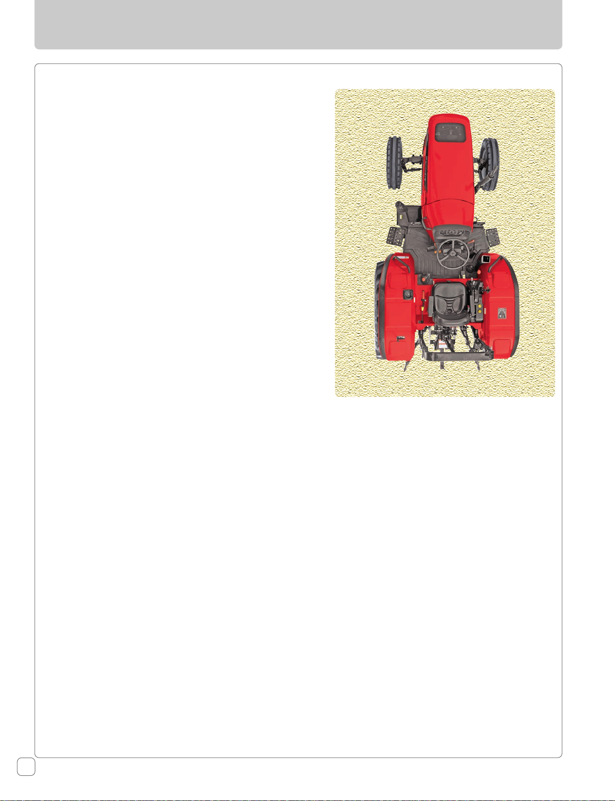
Throughout this manual, the use of the terms LEFT, RIGHT,
FRONT and REAR must be understood, to avoid any
confusion when following the instructions. The LEFT and
RIGHT means left and right sides of the tractor when facing
forward in the driver’s seat. Reference to the FRONT
indicates the radiator end of the tractor, while the REAR,
indicates the drawbar end.
FRONT
LEFT RIGHT
REAR
14
6065 / 6075 2WD & 4WD Rev-00
Page 17
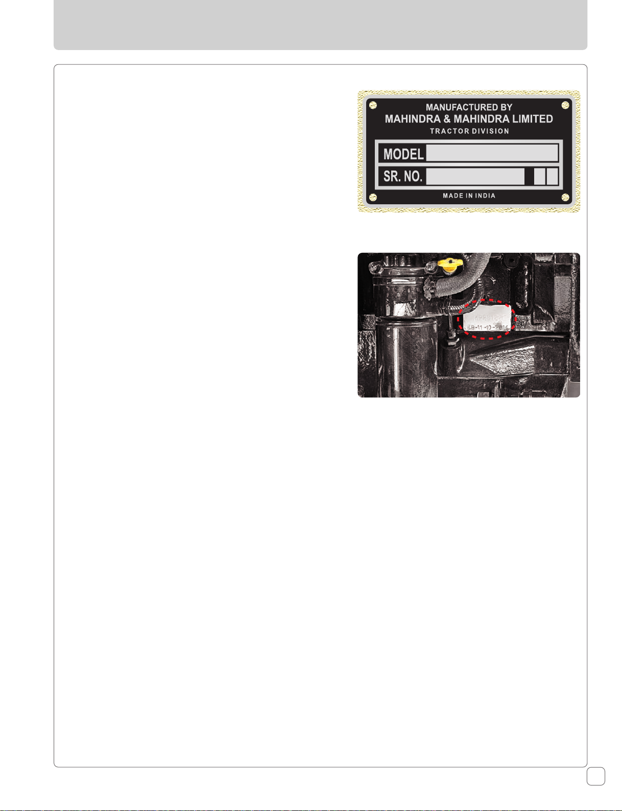
Tractor Serial Number
The tractor serial number can be identified from below
mentioned locations :
1. A plate rivetted on tractor.
2. Number punched on the right side of Engine.
For easy reference, we suggest you to write this number in
the space provided in the owner’s personal data.
When spare parts are required, always specify the tractor
and tractor serial number. This will facilitate faster delivery
and help ensure that the correct part for your particular
tractor is received.
Introduction
A plate rivetted on tractor
Right Side of Engine
6065 / 6075 2WD & 4WD Rev-00
15
Page 18

General Description
General Construction
The transmission case, clutch housing, engine and
front axle are bolted together to form a rigid unit.
Engine
This tractor is fitted with fuel-efficient US EPA certified
Mahindra - VNEM 373 (6075) and VNEM 363 (6065)
engine. This engine is 3 cylinder, turbocharged,
intercooled with high pressure common rail injection
system meeting EPA TIER-4 FINAL emission norms.
Front Axle & Wheels (2WD)
This is a three piece front axle with square tube
design mounted on a central pivot pin. The front
wheels are mounted on taper roller bearings housed
in a hub which itself is mounted on the steering
knuckle. The front track width is adjusted by adjusting
the front axle tubes.
Front Axle & Wheels (4WD)
Front Axle is live front axle, with planetary reduction
gear and with LSD (Limited Slip Differential). The
front wheels are directly mounted on the axle. The
front track is adjustable with adjustment provided
on the rims. The turning angles are all preset.
Power Steering
The Power Steering System consists of a Hydrostatic
Steering Unit (HSU), Hydraulic cylinder, Reservoir
common for Transmission, Hydraulics and Power
Steering.
Rear Axle & Wheels
The rear axle is mounted on bearings and is enclosed
in a removable housing which is bolted to the
transmission case. The rim & disc, fitted with rear
tires, are bolted to the outer flange of rear axle. The
Rear track adjustment is provided on the rims.
Oil Immersed Brakes
Mahindra tractors are provided with independent oil
immersed brakes operated by two independent
pedals which can be latched together for road travel.
A hand brake lever is fitted for parking. To assist in
making sharp turns at slow speeds in the field,
unlatch the brake pedals and depress the right or left
brake pedal as required.
A parking brake lever is fitted on RH side of
operator's seat.
Hydraulic System
The tractor is fitted with fully “live” Hydraulic System.
Using a pump driven directly from the Engine. It is
able to operate the three-point linkage and auxiliary
valve entirely independent of any clutch movement
when changing gear or operating the power take-off.
The Oil reservoir is common with that of transmission.
Three Point Linkages
Three Point Linkage is available in Cat-I & Cat-II
geometry with adjustable lower link.
Electrical System
Clutch
Tractor is fitted with hydraulic control valve to
engage / disengage drive to transmission. For
Independent PTO a separate hydraulically operated
clutch pack is mounted on the PTO Shaft.
Transmission
The transmission is combination type wherein the
Speed shifting is of synchroshift type whereas the
range shifting is of collarshift type. Forward / Reverse
shifting is with wet clutch.
The speed gear shifting arrangement is provided on
RH side of operator’s seat. Speed gears can be
operated in 5 modes.
A 12 volt battery is used to crank the engine with the
starter motor. The electrical system is comprised of
the horn, head lamp, front parking lamp, safety
switch, parking & turn signal lamp, plough lamp,
brake light, instrument cluster, alternator and fuse
box.
Safety
PTO and transmission neutral switch are a standard
feature.
Sheet Metal
Bonnet, scuttle, fuel tank, side panels, front grille &
panel, fenders and bracketaries including floor panels
etc. are constructed of sheet metal. After undergoing
through chemical reaction, it is first primed & then
painted.
16
6065 / 6075 2WD & 4WD Rev-00
Page 19

Owner Assistance
We at Mahindra USA Inc. and your Mahindra Dealer want you to be
completely satisfied with your investment. Normally any problems with
your equipment will be handled by your Dealer’s service department.
Sometimes, however, misunderstanding can occur. If you feel that your
problem has not been handled to your satisfaction, we suggest the
following:
Contact the Owner or General Manager of the dealership, explain the
problem, and request assistance. Your Dealer has direct access to the
Mahindra office. If you cannot obtain satisfaction through your Dealer,
contact the Mahindra USA Inc. office (1-877-449-7771) and provide the
following:
Your Name, Address and Telephone number
Model and Tractor Serial number
Dealer Name and Address
Tractor Purchase Date and Hours used
Nature of Problem
Before contacting Mahindra USA Inc. office, be aware that your
problem is likely to be resolved at your retail Mahindra dealership by
Dealer personnel. So it is important that your initial contact be with
your retail Mahindra Dealer.
6065 / 6075 2WD & 4WD Rev-00
17
Page 20
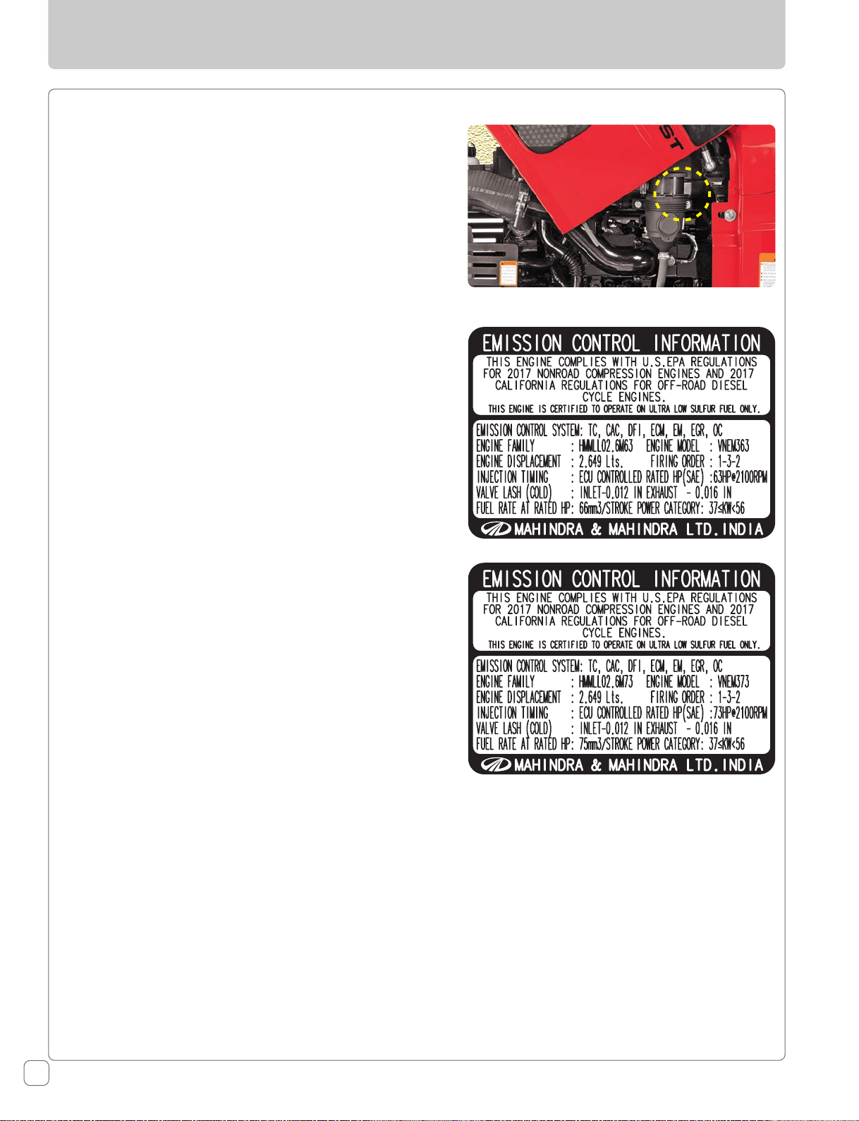
Owner’s Personal Data
A sticker having important engine information is fitted on
the LH side of engine.
Name :
Address :
Tractor Details
Model :
Tractor Serial Number :
Date of Purchase :
Expiration of Warranty :
Nearest Authorized Dealer
Name :
Address :
Telephone No. :
6065 - EPA & CARB Sticker
6075 - EPA & CARB Sticker
Fax No. :
Keep this operators manual safely for regular reference. Ensure that all operators have access to it and
that they understand its contents.
18
6065 / 6075 2WD & 4WD Rev-00
Page 21
Roll Over Protective Structure (ROPS)
Mahindra USA Inc. tractors are fitted with a frame for the
protection of tractor operator to minimize serious operator
injury resulting from accidental roll over. These frames,
known as ROPS, form a safety zone within which the
operator is offered some protection in the event that the
tractor turns over. It is necessary that the tractor operator
fasten the seat belt around him/her to be protected by the
ROPS.
The mounting structure and fasteners forming the
mounting connection with the tractor are part of the ROPS.
(ROPS) Maintenance and Inspection
The ROPS has been certified to industry and/or government
standards. Any damage or alteration to the ROPS, mounting
hardware or seat belt voids the certification and will reduce
or eliminate protection for the operator, in the event of a
roll-over.
R O P S
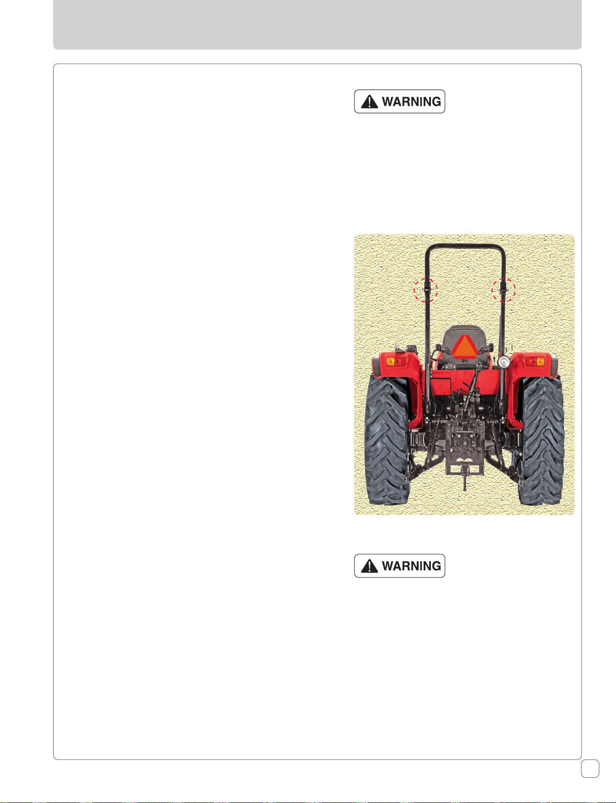
When improperly operated, a tractor can roll
over. For low clearance storage only, the roll bar
may be folded. No protection is provided when
the tractor is operated with the roll bar in the
folded position. Always raise the roll bar
immediately after low clearance storage. Always
use the seat belt when the roll bar is raised.
Seat belts save lives when they are used. Do not
use the seat belt when the roll bar is lowered.
The ROPS, mounting hardware and seat belt should be
checked after the first 100 hrs. of machine operation and
every 500 hours thereafter for any evidence of damage,
wear or cracks. In the event of damage or alteration the
ROPS must be replaced prior to further operation of the
machine. The seat belt must be worn during machine
operation when it is equipped with a certified ROPS. Failure
to do so will reduce or eliminate protection of the operator
in the event of a roll-over.
Substitution of mounting hardware, seat belt etc. with
components not equal to or superior to the original
certified components will void the certification and will
reduce or eliminate protection for the operator in the event
of a roll-over.
Damage of the ROPS
If the Tractor has rolled over or the ROPS has been
damaged (such as striking an overhead object during
transport), it must be replaced to provide the original
protection. After an accident, check for damages to the
1. ROPS 2. Seat 3. Seat belt & seat mountings. Before you
operate a Tractor, replace all damaged parts.
Never attach chains or ropes to the ROPS for
pulling purposes; this will cause the tractor to
tip backwards. Always pull from the tractor
drawbar. Be careful when driving through door
openings or under low overhead objects. Make
sure there is sufficient overhead clearance for
the ROPS.
6065 / 6075 2WD & 4WD Rev-00
If the ROPS is removed or replaced, make
certain that the proper hardware is used to
replace the ROPS and the recommended torque
values are applied to the attaching bolts.
Always wear your seat belt if the tractor is
equipped with a ROPS.
19
Page 22
Safety Instructions
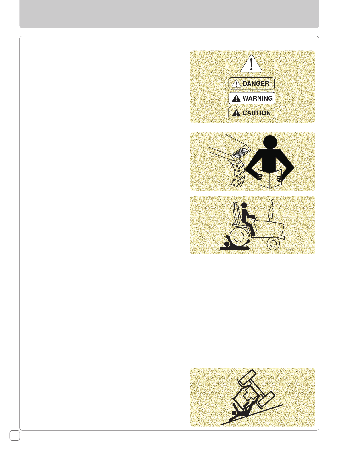
Recognize Safety Information
This symbol means ATTENTION ! YOUR SAFETY IS INVOLVED.
The message that follows the symbol contains important
information about safety. Carefully read the message.
Signal Words
A signal word - DANGER, WARNING OR CAUTION is used
with safety alert symbol. DANGER identifies the most
serious hazards. Safety signs with signal word - DANGER OR
WARNING are typically near specific hazards.
General precautions are listed on CAUTION safety signs.
Read Safety Instructions
Carefully read all safety instructions given in this manual for
your safety. Tampering with any of the safety devices can
cause serious injuries or death. Keep all safety signs in good
condition. Replace missing or damaged safety signs.
Keep your tractor in proper condition and do not allow any
unauthorized modifications to be carried out on the tractor
which may impair the function / safety and affect tractor life.
Safety for Children
Tragedy can occur if the operator is not alert to the
presence of children. Children generally are attracted to
machines and the work they do.
1. Never assume that children will remain where you last
saw them.
2. Keep children out of the work area and under the
watchful eye of another responsible adult.
3. Be alert and shut your machine down if children enter
the work area.
4. Never carry children on your machine. There is no safe
place for them to ride. They may fall off and be run over
or interfere with your control of the machine.
5. Never allow children to operate the machine even under
adult supervision.
6. Never allow children to play on the machine or on the
implement.
7. Use extra caution when backing up. Look behind and
down to make sure are is clear before moving.
8. When parking your machine if at all possible park on a
firm, flat and lever surface; if not, park across a slope.
Set the parking brake(s), lower the implements to the
ground, remove the key from the ignition and lock the
cab door (if equipped) and chock the wheels.
Precautions To Avoid Tipping
Do not drive where the tractor could slip or tip.
Stay alert for holes and rocks in the terrain, and other
hidden hazards.
Slow down before you make a sharp turn.
Driving forward out of a ditch or mired condition could
cause tractor to tip over backward. Back out of these
situations if possible.
20
6065 / 6075 2WD & 4WD Rev-00
Page 23
Use Of ROPS And Seat Belt
The Roll Over Protective Structure (ROPS) has been certified
to industry and/or government standards. Any damage or
alteration to the ROPS, mounting hardware, or Seat belt
voids the certification and will reduce or eliminate
protection for the operator in the event of a roll-over. The
ROPS, mounting hardware, and seat belt should be checked
after the first 100 hours of tractor operation and every
500 hours thereafter for any evidence of damage, wear or
cracks. In the event of damage or alteration, the ROPS must
be replaced prior to further operation of the tractor.
The seat belt must be worn during machine operation when
the machine is equipped with a certified ROPS. Failure to do
so will reduce or eliminate protection for the operator in
the event of a roll-over.
Park Tractor Safely
Before parking the tractor :
Lower all equipments to the ground, bring transmission in
neutral. Engage the parking brake. Stop the engine and
remove the key.
Safety Instructions
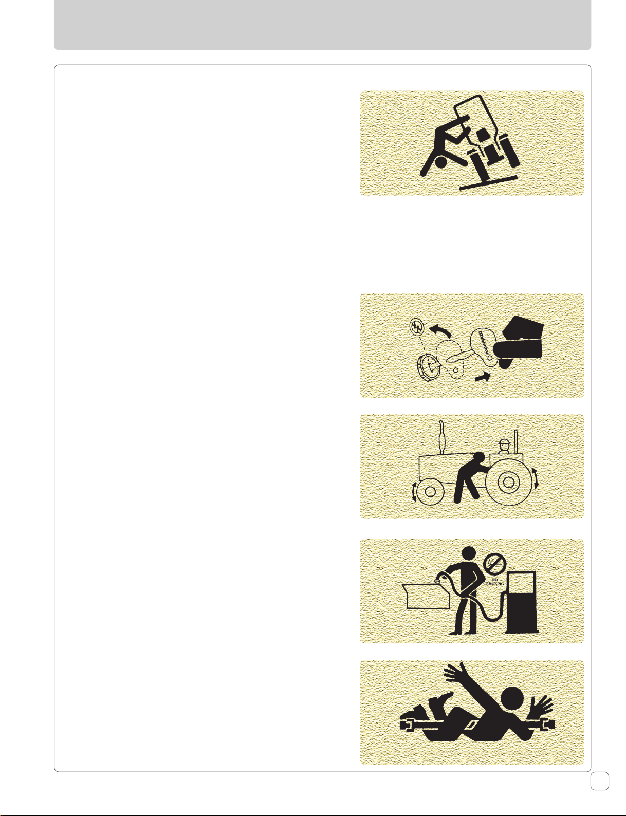
Keep Riders Off Tractor
Do not allow riders on the tractor.
Riders on tractors are subject to injury such as being struck
by foreign objects and being thrown off from the tractor.
Handle Fuel Safely — Avoid Fires
Handle fuel with care. It is highly flammable. Do not refuel
the tractor while smoking or near open flame or sparks.
Always stop engine before refueling tractors.
Always keep your tractor clean of accumulated grease and
debris. Always clean up spilled fuel.
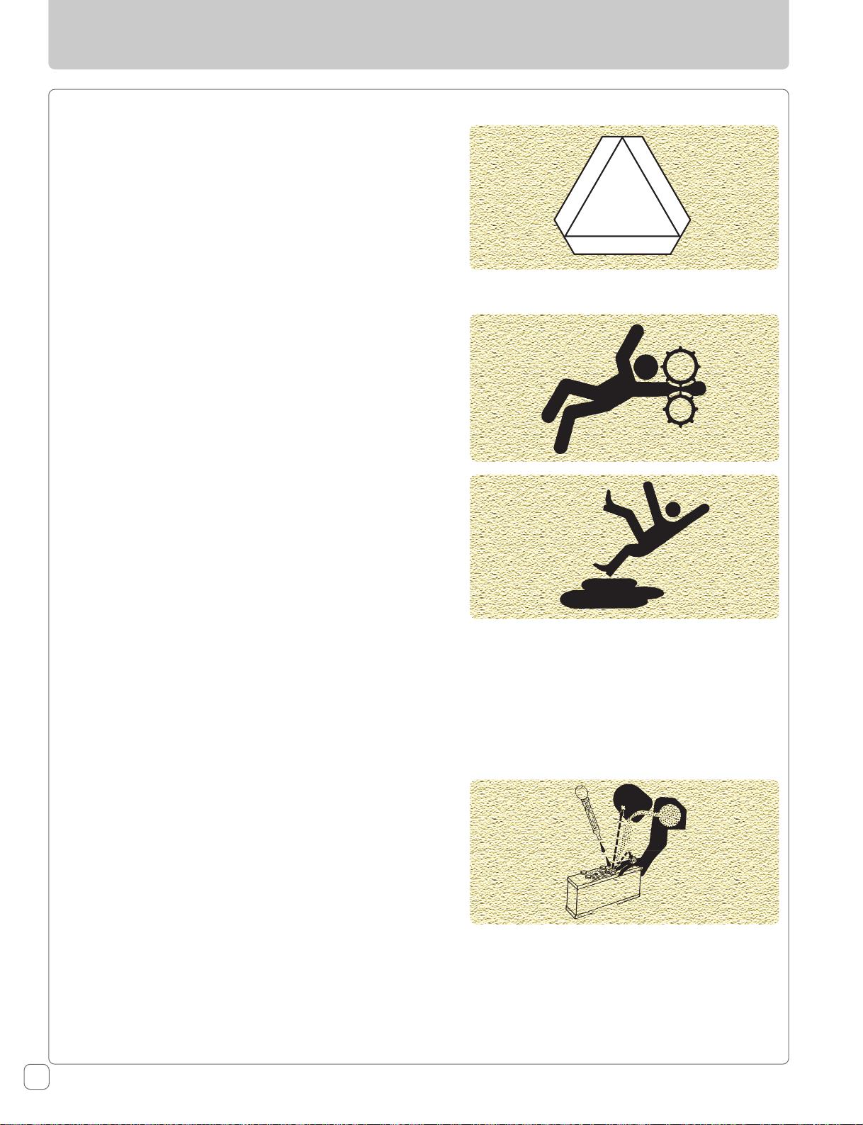
Stay Clear of Rotating Shafts
Entanglement in rotating shaft can cause serious injury or
death.
Keep PTO shields in place at all times.
Wear close fitting clothing. Stop the engine and be sure
PTO drive is stopped before making adjustments,
connections, or cleaning out PTO driven equipment.
6065 / 6075 2WD & 4WD Rev-00
21
Page 24
Safety Instructions
Always Use Safety Lights And Devices
Use of hazard warning lights and turn signals are
recommended when driving the tractor on public roads
unless prohibited by state or local regulations.
Use slow moving vehicle (SMV) sign when driving on public
road during both day & night time, unless prohibited by
law.
Service Tractor Safely
Do not wear a necktie, scarf or loose clothing when you
work near moving parts. If these items were to get caught,
severe injury could result.
Remove rings and other jewellery to prevent electrical
shorts and entanglement in moving parts.
Practice Safe Maintenance
Understand service procedure before doing work. Keep the
surrounding area of the tractor clean & dry.
Do not attempt to service tractor when it is in motion. Keep
body and clothing away from rotating shafts. Always lower
equipment to the ground. Stop the engine. Remove the key.
Allow tractor to cool before any work/repair is performed
on it.
Securely support any tractor components that must be
raised for service work.
Keep all parts in good condition and properly installed.
Replace worn or broken parts. Replace damaged or missing
decals. Remove any buildup of grease or oil from the
tractor.
Disconnect the battery ground cable (- ve) before making
adjustments on electrical systems or welding on tractor.
Prevent Acid Burns
Sulfuric acid in battery electrolyte is poisonous. It is strong
enough to burn skin, cause holes in clothing and cause
blindness if it contacts the eye.
For adequate safety always :
1. Fill batteries in a well-ventilated area.
2. Wear eye protection and acid proof hand gloves.
3. Avoid breathing direct fumes when electrolyte is added.
4. Do not add water to electrolyte as it may splash off
causing severe burns.
If you spill acid on yourself :
1. Flush your skin with water.
2. Flush your eyes with water for 10-15 minutes.
Get medical attention immediately.
22
6065 / 6075 2WD & 4WD Rev-00
Page 25
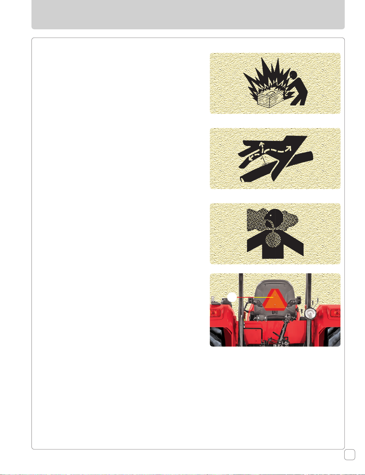
Prevent Battery Explosions
Keep sparks, lighted matches, and open flame away from
the top of battery. Battery gas can explode.
Never check battery charge by placing a metal object across
the poles.
Avoid High-pressure Fluids
Escaping fluid under pressure can penetrate the skin
causing serious injury. Keep hands and body away from
pinholes and nozzles which eject fluids under high pressure.
Do not operate Auxiliary valve when terminal pipes are
open.
If any fluid is injected into the skin. Consult your doctor
immediately.
Safety Instructions
Work In Ventilated Area
Do not start the tractor in an enclosed building unless the
doors & windows are open for proper ventilation, as tractor
exhaust fumes can cause sickness or death. If it is necessary
to run an engine in an enclosed area remove the exhaust
fumes by connecting exhaust pipe extension and drawing
them out with an exhaust fan.
Slow Moving Vehicle Emblem (SMV)
Observe the following precautions when operating the
tractor on road.
1. Ensure that Slow Moving Vehicle (A) emblem affixed on
back side of operator seat is clean and visible.
2. If towed or rear-mounted equipment obstructs this
emblem, install SMV emblem on equipment.
Tractor Runaway
Avoid possible injury or death from possible runaway.
Do not start the engine by shorting across electrical circuit.
The tractor will start in gear if starting circuit is bypassed.
NEVER start engine while standing on ground. Start engine
only from operator’s seat with, transmission in neutral
position, hand brake lever engaged and PTO lever in
disengaged position.
The tractor can start only if the transmission is in neutral
position and PTO lever in neutral as well.
For additional safety keep, the engine starting key in OFF
position, transmission in neutral position, hand brake lever
engaged, PTO lever in disengaged position while servicing
the tractor.
A
6065 / 6075 2WD & 4WD Rev-00
23
Page 26
Safety Instructions
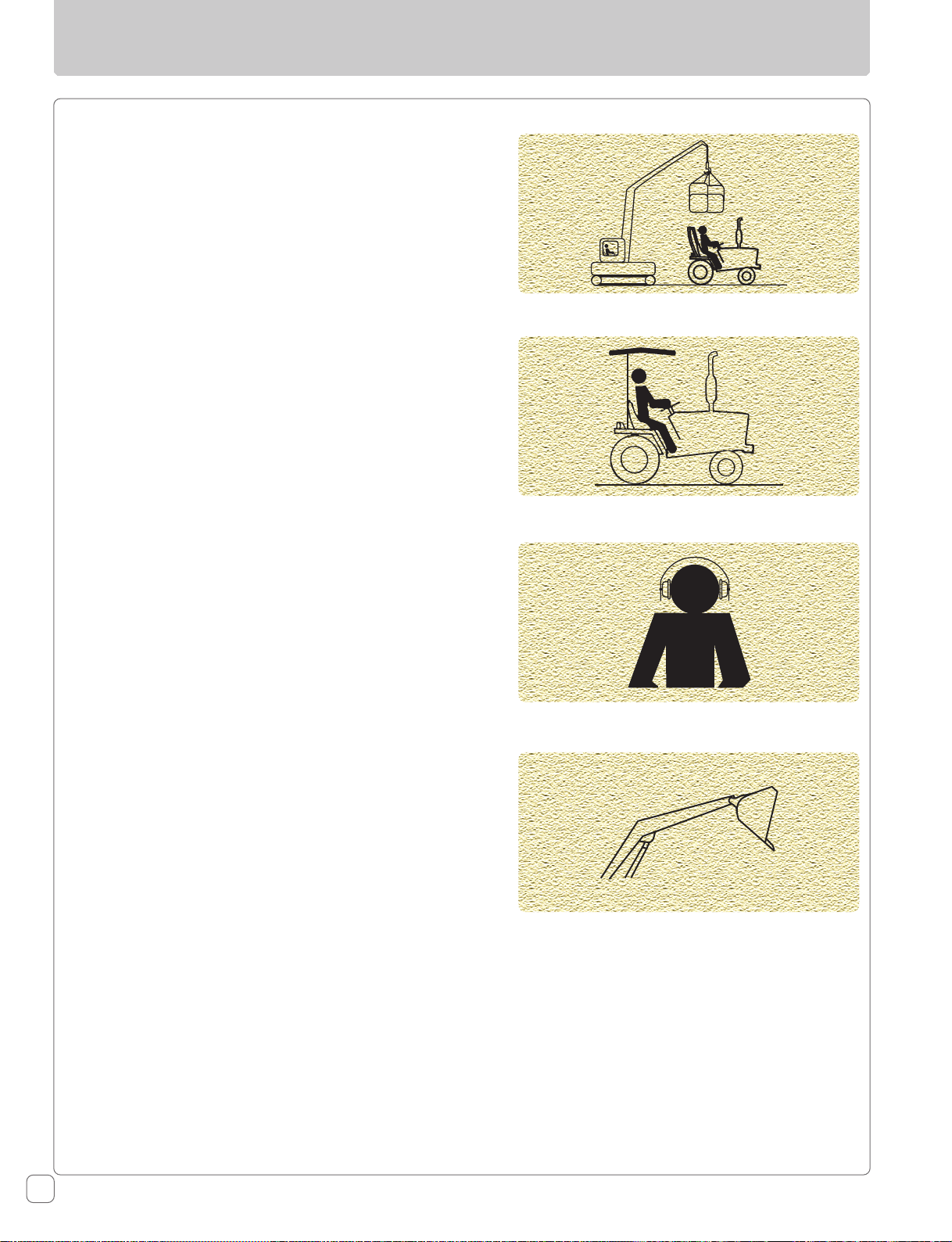
Overhead Protection
This tractor does not have any protection from overhead
falling objects. Do not use this tractor in an application
where there is a risk of falling objects striking the operator.
Sunlight Protection
To Protect the operator from the sun light, it is
recommended to use the canopy.
Hearing Protection
It is recommended to use hearing protection while tractor
is in operation.
Precautions While Using Loader
When using a loader, be conscious of bucket location at
all times, particularly when raising a loader with bucket
rolled back.
24
6065 / 6075 2WD & 4WD Rev-00
Page 27
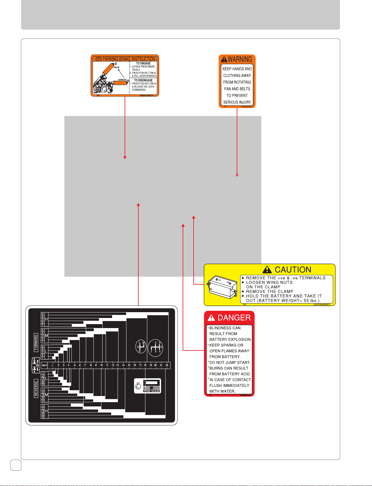
Safety Signs
6065 / 6075 2WD & 4WD Rev-00
25
Page 28
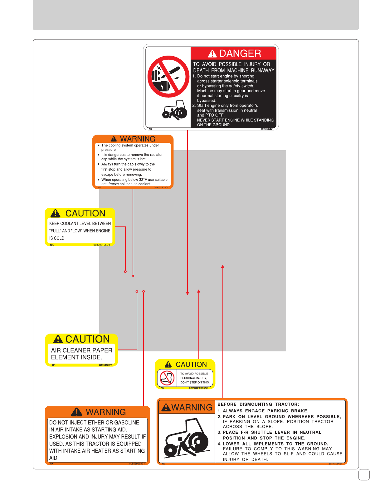
Safety Signs
26
6065 / 6075 2WD & 4WD Rev-00
Page 29
Safety Signs
6065 / 6075 2WD & 4WD Rev-00
27
Page 30

Safety Signs
28
6065 / 6075 2WD & 4WD Rev-00
Page 31

Universal Symbols
Some of the universal symbols have been shown below with an indication of their meaning.
Engine speed
(rpmX100)
Hours, recorded
Engine coolant
temperature
Fuel level
Engine stop
control
Pressurized-open
slowly
Continuous
variable
Warning
Hazard warning
Neutral
Cold start device
"Tortoise" slow or
minimum setting
"Hare" fast or
maximum setting
Transmission oil
pressure
Turn signal
Lights
Horn
Engine oil
pressure
Air filter
Battery charge
Fan
Power take off
engaged
Power take off
disengaged
Lift arm/raise
Lift arm/lower
Transmission oil
temperature
Parking brake
Work lamps
Differential lock
See operator's
manual
MIL
(Malfunction
Indicator Lamp)
6065 / 6075 2WD & 4WD Rev-00
Check Engine
Indicator
29
Page 32

LH & RH View of Engine
1
2
3
LH View : 1. EGR Cooler 2. Fuel Pump 3. Starter Motor 4. Fuel Filter
5
6
4
7
8
RH View : 5. Exhaust Manifold 6. Hydraulic Tandem Pump 7. Dipstick Engine 8. Engine Oil Filter
30
6065 / 6075 2WD & 4WD Rev-00
Page 33

Lamps
Front View :
1. Front Turn Signal (RH)
2. Position Lamp / Reflector (RH)
3. Front Position (RH)
4. Head Lamp (RH)
5. Front Turn Signal (LH)
6. Position Lamp / Reflector (LH)
7. Front Position (LH)
8. Head Lamp (LH)
1
5
2
3
4
6
7
8
Rear View :
1. Rear Turn Signal (LH)
2. Position Lamp / Reflector (LH)
3. Rear Brake Lamp (LH)
4. Rear Turn Signal (RH)
5. Position Lamp / Reflector (RH)
6. Rear Brake Lamp (RH)
7. Plow Lamp
1
2
3
6065 / 6075 2WD & 4WD Rev-00
4
5
6
7
LH - Left Side
RH - Right Side
31
Page 34

Controls, Instruments & Operations
The following pages in this section detail the location and
function of various instruments, switches and controls on
your tractor. Even if you operate other tractors, you should
read through this section of the manual and ensure that
you are thoroughly familiar with the location and function
of all the features of your new tractor.
Do not start the engine or attempt to drive or operate the
tractor until you are fully accustomed to all the controls. It
is too late to learn once the tractor is moving. If in doubt
about any aspect of operation of the tractor consult your
Mahindra USA Inc. Tractor Dealer.
This section explains briefly the operation of instruments,
and controls. Full details wherever necessary will be found
in forthcoming chapters at relevant operating sections.
Instrument Cluster
The operator must be thoroughly acquainted with the
location and use of all instruments and controls regardless
of experience, must read this section carefully before
attempting to operate the tractor.
Operator Controls - Front
Operator Controls - LH, RH
32
Switches
6065 / 6075 2WD & 4WD Rev-00
Page 35

Instrument Cluster
1
2
3
4
5
6
7
8
9
10
11
22
21
20
19
18
17
16
15
14
13
12
Instrument Cluster
The Instrument Cluster is a descriptive unit that gives the user various indications about the working of the
tractor and its various features. It consists of the following.
1. Engine Coolant Temperature Warning Indicator
2. Air Filter Clogging Indicator
3. Check Engine Indicator
4. High Beam Indicator
5. Clutch Over Ride Indicator
6. Gear Neutral Indicator
7. Fuel Level Gauge
8. 4WD Indicator
9. LH Turn Indicator
10. Tachometer
11. Trip Hour Indicator
12. Tractor Run Hour Indicator
13. RH Turn Indicator
14. Water In Fuel Indicator
15. Service Reminder Indicator
16. Coolant Temperature Gauge
17. Cold Start Device Indicator
18. PTO Indicator
19. Parking Brake Indicator
20. MIL Indicator
21. Battery Charging Indicator
22. Low Oil Pressure Indicator
6065 / 6075 2WD & 4WD Rev-00
33
Page 36

Instrument Cluster
Engine Coolant Temperature Warning Indicator
This is a Red LED and is located on top of tachometer. It will
glow continuously when temperature of coolant rises above
0
228.2
RED band under such condition. Also to warn the operator,
A beeper will also give an audio warning. (60 beeps / Min)
Air Filter Clogging Indicator
This is an Amber LED and glows when Air filter is clogged.
This gives an indication to the customer that the air filter
needs to be cleaned for proper functioning.
Check Engine Indicator
This indicator will glow when the starter switch is turned to
"ON" position. This indicator will turn-off after engine is
CRANKED. A malfunction other than Emission, such as
Sensor failures would be indicated by a continuously
"GLOWING" or "BLINKING" Indicator, even past CRANKING of
the engine. In such an event, get the problem rectified by
an authorized Mahindra Dealer.
High Beam Indicator
This is a Blue LED and glows when Head Lamps are
operated in High Beam.
Clutch Over Ride Indicator
Optional feature: This is an Amber LED & Glows when
clutch Pedal is pressed for more than 10 sec.
This symbol will be glowing if the feature is equipped.
Gear Neutral Indicator
This is a Green LED and glows when tractor is not engaged
in any speed gear (in neutral position.)
Fuel Gauge
The Fuel Gauge is displayed on the left side of rpm meter
when viewed from the driver’s seat. It indicates quantity of
fuel available in the fuel tank. The indication is divided into
9 stages. The Red zone indicates that the fuel level is less
and the tractor should be refueled for uninterrupted run.
Low fuel indication & buzzer ON at 2nd Graduation & OFF at
3
34
F. The pointer of Temperature gauge will lie in the
Graduation Gallons / Liters
E 3.43 / 13
1 5.55 / 21
2 7.40 / 28
3 9.51 / 36
4 11.62 / 44
5 13.21 / 50
6 15.85 / 60
7 17.96 / 68
F 21.13 / 80
rd
Graduation. Buzzer sound at the rate of 15 beeps per min.
Continued operation of
engine despite the high
temperature warning
indicator glowing may lead to
engine seizure.
6065 / 6075 2WD & 4WD Rev-00
Page 37

4WD Indicator
This is a Green LED and glows when 4WD is engaged. This
LED will glow only in 4WD tractor version.
Turn Indicator
These are Green LEDs. LH and RH turn indicators are
provided to indicate the direction of turning. A blinking LH
turn indicator implies that the LH Turn Signal indicator of
tractor is ON whereas a blinking RH turn indicator implies
that the RH Turn Signal indicator of tractor is ON.
No. of flashes of these LEDs: 60-120 counts/minute
If the count is more than 140 per minute, then it is an
indication that one of the bulbs is not functioning.
Tachometer
This gives the number of Revolution per Minute of the
engine. To arrive at the rpm value at any given point of
time, multiply the pointer reading by 100.
Example: If the reading shows 15, the actual engine rpm
value = 15 x 100 = 1500
Instrument Cluster
Trip Hour Counter
This is a LCD hour counter located under the tachometer.
It is operated by signal from ECU, when the engine is
running. Trip hour counter displays the running hours for
the particular trip. The run hour is calculated in real time,
i.e. 60 minutes of tractor run is calculated as 1 hour only.
After 999 hours is completed, the count restarts from 0.
The blinking of the symbol indicates that the run time is
counted on real time.
Tractor Run Hour Counter
This is a LCD hour counter located under the tachometer.
It is operated by signal from ECU, when the engine is
running. Hour counter displays the cumulative engine
running hours. The run hour is calculated in real time, i.e.
60 minutes of tractor run is calculated as 1 hour only.
Trip Hour Reset Button
This is located on cluster bezel and is used to reset the trip
hour meter as and when required. This can be done by
continuously pressing the button for 5 seconds.
Water In Fuel Indicator
This is Amber LED and glows when water is accumulated in
the fuel filter. The operator has to drain the water by
opening the sensor in fuel filter.
6065 / 6075 2WD & 4WD Rev-00
Failing to drain the water will lead to reduced
engine performance and life. After draining the
water tighten the sensor.
35
Page 38

Instrument Cluster
Service Reminder Indicator
This is an amber color LED and glows continuously when
the service of tractor is due. This function is set for first
th
100
hour and thereafter for every 400th hour of engine
running. The operator is thus indicated for General Service
Due. Resetting can be done by authorized Mahindra Dealer
as soon as the general service is done.
Coolant Temperature Gauge
The temperature gauge is displayed on the right side of
instrument panel when viewed from the driver’s seat. This
gauge indicates coolant temperature of the engine. When
the pointer lies in RED band:
1. Indicates the engine coolant temperature is going to
exceed the limit.
2. Identify the cause by running the engine at low idle rpm
for some time before switching OFF.
3. Further engine operation should be done only after
elimination of the problem.
Graduation Temperature (
0
F)
C 104
1 105.8 - 122
2 131
3 132.8 - 167
4 168.8 - 215.6
5 222.8 - 224.6
6 226.4
7 226.4 - 228.2
H 231.8 - 248
High temperature indication will blink (30 cycles / min) at
0
228.2
F and switch off at 226.40F.
High temperature Buzzer will give 60 beep / min at
0
228.2
F and switch off at 226.40F.
Cold Start Device Indicator
When the key is turned to 2nd position, the cold start
indicator glows to indicate the activation of heater element
provided in engine’s intake elbow. The indicator continues
to glow for approx. 45 seconds. A timer controls this time.
1. Turn the key to "ON" position and wait till the heater
indicator is goes-off.
2. Crank the engine when the heater indicator light is off
36
6065 / 6075 2WD & 4WD Rev-00
Page 39

PTO Indicator
This is Amber color indication for PTO. This indicates when
PTO is ON position.
When using Auto Mode of PTO switch, If clutch is pressed
or PC lever is lifted fully. Then this LED will blink.
Parking Brake Indicator
This is a Red LED and glows when the Parking Brake is
applied.
MIL Indicator
This indicator will glow when the starter switch is turned to
“ON” position. This indicator will turn-off after engine is
CRANKED.
A malfunction in the electronic emission control system
(ECU) is indicated by a continuously “GLOWING” or
“BLINKING” Indicator, even past CRANKING of the engine.
In such an event, get the problem rectified by an authorized
Mahindra Dealer.
Instrument Cluster
The park brake should not be used for more
than 1 hours with ignition on condition as this
will result in damage of brake lamps.
Battery Charging Indicator
This is a Red LED and glows when the battery is not getting
charged. Also this LED will glow during ignition ON and
should go OFF immediately after engine rpm reaches
800 rpm.
During engine running, if this LED glows it
means Battery is not getting charged. A beeper
Low Oil Pressure Indicator
This is a Red LED and glows when the engine is operating
at Low oil pressure. & also to warn the operator, a beeper
will also give an audio warning.
This indicator will also glow when the Key is in ON position
before starting the engine and continue to glow till engine
oil pressure builds up after starting the engine.
Beeper Output Provision
The Beeper will beep at different rate during following conditions.
Description Beeps/min
High Coolant Temperature 60
will also give an audio warning in such case.
Continued operation of engine despite the low
oil pressure indicator glowing may lead to
engine seizure.
Engine Low Oil Pressure 40
Low Battery Charge 30
Low Fuel 15
Air Filter Clog 10
6065 / 6075 2WD & 4WD Rev-00
37
Page 40

Switches
1. Ignition Key Switch
This is a key operated 3-way rotary switch located on RH
side of steering column cover. It operates in clockwise
direction and the positions are as follows:
1. OFF
2. IGNITION: This Position gives a readiness to the
electrical circuit for operating plough lamp switch,
brake light switch and turn signal switch. This puts ON
the supply to instrument cluster and readiness to the
electrical circuits for operation of light switch.
3. START: Turning the key to this position activates the
starting circuit for starting the engine. When released,
the key springs back to ignition position.
2. Steering Column Mounted Combination Switch (A)
This is multi-functional switch mounted on steering column.
It consists of following operation switches.
1. Light Control
2. Dipper
3. Turn Signal
4. Horn
3.1 Light Switch
This is 3-way rotary switch. The operations are as follows:
1. Off
2. Illuminates instrument cluster illumination lamp and
position lamps.
3. Illuminates low/high beam of head lamp in addition to
the position lamp with respect to the position of the
dipper.
3.2 Dipper Switch
This is a 3 way lever switch. It operates in up and down
direction and the operations are as follows.
Center : Operate Low beam of Headlamp
Down side : Operate High beam of Headlamp
Up side : Passing through (Momentary switch)
3.3 Turn Signal Switch
This is 3-way rotary lever switch. It operates in front and
forth direction and the positions are as follows.
A
Left Turn
L
B
Neutral Position
Right Turn
R
Center : OFF
Forward : Operates left turn signal lamp
Rearward : Operates right turn signal lamp
3.4 Horn
This is push button switch (B). Pressing this switch will
enable the horn and releasing it will disable the Horn.
38
6065 / 6075 2WD & 4WD Rev-00
Page 41

3. Plough Lamp Switch (C)
This is a 2-way rotary switch located on the LH side of the
scuttle extension cover.
1. Off
2. Illuminates Plough Lamp
4. Hazard Switch (D)
This is push type switch located bottom side of Steering
column cover. The operations are as follows.
On Position - Operates left and right turn signal lamp
simultaneously. This operation can be performed even if the
key switch is in OFF position.
Switches
C
5. Neutral Safety switch
This switch ensures that the engine cranks only when the
gear is in neutral position.
6. Brake Switch
The function of this switch is to automatically turn on the
stop lamp when the brake pedal is pressed.
7. Forward Reverse Switch (E)
This is a 3 way lever switch. It operates by lifting the lever
then up and down direction and the operations are as
follows.
Center : Neutral position.
Forward : Vehicle move in forward direction.
D
NOTE: The starting circuit is interconnected
with transmission and PTO neutral switches.
Thus the engine will not start unless the
transmission and PTO are in neutral.
E
Rearward : Vehicle move in reverse direction.
1. Moving the lever up and down without lifting, can
damage the switch.
2. Don’t hold the lever while getting on or off the tractor.
6065 / 6075 2WD & 4WD Rev-00
39
Page 42

Switches
8. PTO AUTO / MANUAL Switch
To switch on the PTO, First Mode to be selected. The Switch
With identification is shown below.
To Select the AUTO mode, Knob to be turn to Right side.
To Select the MANUAL Mode, Knob to be turn to Left side.
To bring to neutral position, turn the knob to center
position.
Then followed by Switch on the PTO switch.
9. PTO ON/OFF Switch
This switch is used to engage the PTO Clutch with PTO
shaft. The Operation of the switch is as follows.
To switch ON the PTO: PUSH and Rotate the Knob, Clock
wise as shown in image below.
To Switch OFF the PTO: Press the knob.
PTO is operated electrically. PTO can be operated by using
a combination of "PTO ON-OFF switch" and "PTO Mode
selection Switch".
After switching ON the "PTO ON / OFF switch" the operator
has a CHOICE to select AUTO or MANUAL MODE through
"PTO Mode Selection Switch".
The PTO will turn-Off if the "PTO ON/OFF Switch" or
"PTO Mode selection Switch" is in OFF position.
Refer to the table shown for combinations of PTO
operations.
For operation switch knob to be pressed and
then to be rotated. Failing to do this will lead to
permanent damage of switch
PTO Mode PTO ON/OFF switch Clutch pedal PC lever position PTO Shaft PTO indication
selection switch in cluster
Manual mode OFF Any Any Stationary OFF
Manual mode ON Any Any Rotate ON
Auto mode OFF Any Any Stationary OFF
Auto mode ON Not pressed Lower position Rotate ON
Auto mode ON Pressed Any Stationary Blink
Auto mode ON Any Lifted position Stationary Blink
Clutch pedal "Any" – Pressed or depressed condition of pedal
PC lever "Any" – Lowered or lifted position of PC lever
40
6065 / 6075 2WD & 4WD Rev-00
Page 43

Seven Pole Socket:
It is used to provide supply for any trailer which is attached
at the rear.
The seven pins have the following functions.
PIN NO FUNCTION WIRE COLOUR
1 Left direction indicator White
2 Empty Empty
3 Ground Yellow
4 Right direction indicator Red
5 Right rear position Brown
6 Stop Blue
7 Left rear position Green
Mobile Charger Socket:
Switches
This is a power socket which provides 12V supply. This can
be used for charging mobiles or other electrical devices.
NOTE:
Maximum Power Rating : 7A
This socket is only provided for mobile charging application.
Fuse Box:
The fuse box is located inside the scuttle hood. To access
the Fuse box, open the Extension cover behind the Clutch
pedal.
Always replace fuse with correct rating. Failing to do this
will damage the wiring harness.
6065 / 6075 2WD & 4WD Rev-00
41
Page 44

Controls
Tractor Front
1
2
3
Operator’s Front Side Controls
Tractor Front
4
5
6
7
8
14
9
10
11
12
13
Operator’s LH & RH Side Controls
Controls
1. F-R Shuttle Shift Lever
2. Clutch / Inching Pedal
3. Tilt Steering Pedal
4. Hand Throttle
5. Brake Pedal LH
6. Brake Pedal Latch
7. Brake Pedal RH
8. Foot Throttle
9. Auxiliary Valve Lever
10. Position Control Lever
11. Draft Control Lever
12. Gear Shifter Lever
15
16
17
13. Differential Lock Pedal
14. PTO Lever
15. Parking Brake
16. Range Shifter Lever
17. 4WD Engagement Lever
42
6065 / 6075 2WD & 4WD Rev-00
Page 45

Operator Seat
The operator seat can be adjusted for position, tilt and
weight of operator. These adjustments are to be done prior
to starting the engine.
Adjusting Seat Position
1. Sit on the operator seat.
2. Lift the lever (D) upwards & slide the seat forward or
rearward to desired position.
3. Release lever to lock seat in position. Ensure that all
controls can be accessed easily.
Weight Adjustment
To achieve optimum seat suspension, turn the knob (B) till
the weight indicator registers your approximate weight on
indicator (C).
Tilt Adjustment
To achieve optimum seat tilt, turn the knob (F) till the
desired angle of tilt is achieved.
Using Seat belt
Use a seat belt when you operate with roll over protective
structure (ROPS) to minimise chance of injury from
an accident such as an overturn. Do not jump if machine
tips.
Fasten Seat belt
1. Pull belt end (A) across operator lap.
2. Install tab into buckle (G). A click will be heard when
the tab locks into the buckle.
Release Seat belt
Press red button (E). The seat belt will automatically retract.
Controls
F
E
G
Attempting to adjust the seat while driving the
tractor may cause the operator to lose control
of the tractor.
Do not use seat belt if operating without a
ROPS or with an optional folding ROPS in the
folded position.
A
B
C
D
Tilt Steering
The steering can be tilted towards or away from the
operator as per the need and convenience of operator and
is recommended to be done in tractor parked condition.
Tilt Adjustment
1. Park the tractor safely.
2. Press the tilt steering pedal (H) by foot.
3. Tilt the steering wheel to desired position.
4. Release foot pressure on the pedal.
Attempting to adjust the steering wheel while driving the
tractor may cause the operator to lose control of the
tractor.
Lock the steering wheel in position before driving the
tractor.
6065 / 6075 2WD & 4WD Rev-00
H
43
Page 46

Controls
Hand Throttle Operation
Use the Hand Throttle Lever to set a constant engine speed
for stationary operation or for field operation wherever
desired.
Increasing Engine Speed : Pull throttle lever towards
operator as indicated in the sticker on the dashboard.
Engine Tachometer Speeds :
a. Low Idle speed - 850 ± 50 rpm
b. Rated engine speed - 2100 rpm
c. High Idle speed - 2300 rpm ± 50 rpm
Decreasing Engine Speed : Push throttle lever away from
the operator as indicated in the sticker on the dashboard
Constant Speed Setting : Certain operations may require
a particular engine speed. This can be achieved by resting
the Hand Throttle Lever in a position where you get the
desired engine speed.
Foot Throttle Operation
When tractor operation requires repeated speed change,
use the foot throttle pedal to temporarily increase engine
speed above hand throttle setting. We recommend to keep
the hand throttle at minimum and use foot throttle when
driving on highway.
a. Set the hand throttle lever at desired rpm.
b. Depress foot throttle pedal to Increase Engine rpm.
c. Release foot throttle pedal to decrease Engine rpm to
achieve the previous engine speed set by hand throttle
lever.
4WD Engagement Lever
This lever is located on L.H side of operator’s seat. It is used
to engage or disengage the drive to front wheels and is
recommended to be done with tractor in stand still
condition.
1. Depress clutch pedal and stop the tractor motion
completely.
2. Lift the lever upwards to engage the drive to front
wheels.
3. Press the lever downwards to disengage the drive.
44
Do not engage or disengage the 4WD lever
while the tractor is in motion.
6065 / 6075 2WD & 4WD Rev-00
Page 47

Brake
Two independent brake pedals are provided for LH and RH
wheel braking to enable sharp turns during field
operations.
To make a sharp turn to the left, depress LH brake
pedal (A).
To make a sharp turn to the right, depress RH brake
pedal (B).
The brakes can be latched together to act simultaneously by
means of brake pedal latch (C) as follows,
1. Rotate brake pedal latch (C) until it locks into LH brake
pedal (A).
2. Depress any of the brake pedal to slow or stop the
tractor.
3. When brakes are applied with brake pedals latched
together, the tractor should stop in a straight line.
Check and adjust brake settings if the tractor is dragged
to either side on applying brakes.
The hand throttle lever should be brought to low idle rpm
position before applying brakes.
Controls
A
C
B
Using unlocked brakes to stop the tractor at
high speeds may cause accidental turning or
tipping.
Lock pedals together when not using the turn
brakes or for road travel.
Slow down before making a turn.
Do not apply independent brakes while
an attachment is engaged with the ground.
This can cause damage to the attachment, three
point linkage of tractor and may also result in
tipping of the tractor.
Parking Brake
The Parking brake is provided on LH side of operator’s seat.
To Engage
1. Latch & press brake pedals.
2. Press push button (A) and pull lever upwards.
To Disengage
Press push button (A) and release the lever downwards.
6065 / 6075 2WD & 4WD Rev-00
Released
Applied
Always lock the parking brake when the tractor
is left unattended.
45
Page 48

Controls
Differential Lock Pedal
This pedal located on the RH side of the operator's seat
when depressed by heel pressure, operates a differential
lock mechanism which locks both of the axle shafts
together.
Its purpose is to overcome the one-wheel slip
encountered under bad field conditions, especially when
ploughing or when hauling heavy trailers on slippery
surfaces.
Differential lock is designed for occasional use. Do not
attempt to lock differential while,
a. The tractor is in high speed.
b. Turning tractor.
Releasing the pedal pressure disengages the differential
lock.
Clutch / Inching Pedal
Disengaged
Engaged
The differential lock design is solely for the use
with pneumatic tires. If steel wheels, girdles etc.
are fitted, the differential lock should be
removed as a precaution.
Attempting to turn the tractor while differential
lock is engaged may result in damage to
transmission.
Tractor is fitted with hydraulic control valve to engage /
disengage drive to transmission. For independent PTO
aseparate hydraulically operated clutch pack is mounted on
the PTO shaft.
Main clutch gives drive to the transmission and is operated
by clutch pedal.
Depressing the clutch pedal fully disengages the drive to
gear box for selection of different speeds.
46
6065 / 6075 2WD & 4WD Rev-00
Page 49

PTO
This tractor is equipped with Dual PTO option, namely 540
and 540E.
To select required PTO rpm, shift the lever and put it in
required position.
PTO will not be operable in case of Neutral position.
540
With 540 position selected and the engine running at the
indicated speed, the PTO shaft will rotate at 540 rpm.
540E
540E is an economy mode that allows the PTO to rotate at
540 rpm with a lower engine speed.
Controls
540 540E
Neutral
The free play of the PTO clutch is preset at
factory. It is not recommended to adjust the
same through PTO clutch linkage.
NOTE :
The clutch may require replacement due to
normal wear, if loss of power to PTO shaft is
observed when PTO lever is engaged. Your local
Mahindra dealer should identify and rectify the
issue.
When PTO drive is not in use keep the PTO
lever in disengaged position.
Firmly apply the parking brakes, place all gear
shift levers in neutral and block all four wheels
before operating any stationary PTO equipment
Do not approach or work on the PTO shaft or
equipment while the PTO is in motion.
Shut-off engine and the PTO and wait for all
movement to stop before working on the PTO
or equipment.
6065 / 6075 2WD & 4WD Rev-00
47
Page 50

Controls
Range Shift Lever
This lever is located on L.H side of operator’s seat. This lever
has three positions as follows,
1. Low – for Low speed range
2. Neutral
3. Medium – for Medium speed range
4. High – for High speed range
This lever enables 3 different speed options for every Speed
Gear selection. The lever can be engaged as follows,
1. Depress Clutch pedal and stop tractor motion
completely.
2. Choose High / Medium / Low speed range to match
work application.
3. Release clutch pedal gradually.
Refer Chart for road speed of tractor in different positions.
Never shift Range shift lever while the tractor is
in motion.
Tractor road speed in different positions of F-R Shuttle, Range and Speed Levers.
6065 2WD/4WD 6075 4WD
Gears
L1 1.8 1.7 1.1 1.0
L2 2.5 2.4 1.6 1.5
L3 3.6 3.5 2.3 2.2
L4 4.6 4.4 2.9 2.7
L5 6.2 5.9 3.8 3.7
M1 5.2 4.9 3.2 3.1
M2 7.5 7.1 4.7 4.4
M3 10.8 10.3 6.7 6.4
M4 13.6 13.0 8.4 8.1
M5 18.2 17.4 11.3 10.8
H1 9.7 9.3 6.1 5.8
H2 14.1 13.5 8.8 8.4
H3 20.3 19.4 12.6 12.0
H4 25.6 24.4 15.9 15.2
H5 34.4 32.8 21.4 20.4
Forward Reverse Forward Reverse
Kmph mph
Gears
L1 1.8 1.7 1.1 1.1
L2 2.6 2.5 1.6 1.6
L3 3.8 3.6 2.3 2.2
L4 4.8 4.5 3.0 2.8
L5 6.4 6.1 4.0 3.8
M1 5.4 5.1 3.3 3.2
M2 7.8 7.4 4.8 4.6
M3 11.2 10.7 6.9 6.6
M4 14.1 13.4 8.7 8.3
M5 18.9 18.0 11.8 11.2
H1 10.1 9.6 6.3 6.0
H2 14.6 14.0 9.1 8.7
H3 21.1 20.1 13.1 12.5
H4 26.5 25.3 16.5 15.7
H5 35.6 34.0 22.1 21.1
Forward Reverse Forward Reverse
Kmph mph
48
6065 / 6075 2WD & 4WD Rev-00
Page 51

F-R Shuttle Shift Lever
This lever is located on L.H side of Steering. This lever
enables to choose the direction of tractor motion and has
three positions as follows,
1. Forward – for forward motion of tractor.
2. Reverse – for rearward motion of tractor.
3. Neutral
The lever can be engaged as follows,
1. Lift the Forward / Reverse shuttle shift lever from its
neutral position and shift to choose Forward or Reverse
mode as desired.
2. Forward / Reverse shifts can be made without
depressing clutch pedal at any speed.
Speed Shift Lever
Controls
This lever is located on RH side of operator's seat. This lever
has six positions. This lever enables 5 different speed
options within a particular "Range Gear" selection. The road
speed increases in higher gears.
1. Depress Clutch pedal completely.
2. Choose any one gear to match work application.
3. Release clutch pedal gradually.
The gears can be shifted on-the-go.
Refer speed chart (page-48) for road speed of tractor in
different positions.
Auxiliary Valve
The auxiliary valve is equipped with 2 lever operated valves.
Each valve has four positions as follows :
a. Float (F) Detent
b. Lower (L) Detent
Front
c. Neutral (N)
d. Raise (R) Detent
The lever returns to neutral position from lower or raise
position when the cylinder is fully retracted / extended.
Keep the levers in neutral position (N) when auxiliary valve
is not in use.
6065 / 6075 2WD & 4WD Rev-00
Failure to comply will result in overheating the
hydraulic oil and may cause injury or damage.
49
Page 52

Controls
Opening the Hood
The hood is hinged at the rear side and opens away from
the operator as follows,
1. Pull the lever (A). The hood will unlock.
2. Lift the hood upwards by hand. Two gas springs (B)
provided inside will assist in minimising the effort for
lifting.
3. The bonnet strap (C) provided on the bonnet will help
the hood to stop at desired angle.
4. The mounting of the bonnet strap on the radiator
bracket can be removed to open the bonnet fully.
Closing the Hood
1. Ensure the bonnet strap (C) is mounted on both the
ends on the tractor.
2. Pull and press the hood downwards until it locks.
A
C
50
B
6065 / 6075 2WD & 4WD Rev-00
Page 53

Hydraulic System & Operation
1
2
3
4
5
Three Point Linkage
1. Top Link.
2. Lift Arm LH
Quadrant Assembly
13. Position Control Lever
14. Position Control Stop Screw
6
7
8
9
10
11
12
Tractor Front
6065 / 6075 2WD & 4WD Rev-00
16
15
14
13
3. Adjustable Lift Rod LH
4. Stabiliser LH
5. Lower Link LH
6. Lift Arm RH
7. Draft Sensing Bracket
8. Adjustable Lift Rod RH
9. Stabiliser RH
10. Lower Link RH
11. Drawbar
12. Towing Pin
15. Draft Control Lever
16. Draft Control Stop Screw
51
Page 54

Position Control - Operation
Quadrant Assembly
This system incorporates a Position control and a Draft
control. Both these controls are within easy reach of the
operator.
Position Control
This lever (D) controls the lifting and lowering of all
implements used on the three point linkage.
1. Moving the lever Forward will lower the implement.
The operator must be thoroughly acquainted
with the location and use of all controls
regardless of experience, must read this section
carefully before attempting to operate the
tractor.
2. Moving the lever Rearward will raise the implement.
The control can also be set by PC stop screw (C) to govern
the height of out-of-ground implements such as mowers,
rakes etc., so that the implement can be lowered to exactly
the same height at the commencement of each turn.
PC lever (D) should be used for the following applications:
1. TRANSPORT of implements and turn around at the end
of the field.
2. CONSTANT DEPTH of implements on level terrain and
for non-ground engaging implements such as spreaders
or sprayers. Place the PC lever at desired depth.
Setting of Position Control
1. Move the DC lever (A) to its forward most position.
2. Move the PC lever (D) back to the upper limit and allow
the implement to lift fully.
3. Move the PC lever (D) forward until the implement has
reached the desired working height.
4. Set the position control stop screw (C) against the PC
lever and tighten the knob.
Whenever the PC lever is returned to the front position till
the stopper, the implement will return to the same preset
height.
B
A
C
D
Tractor Front
C
D
B
A
52
Tractor Front
6065 / 6075 2WD & 4WD Rev-00
Page 55

Draft Control - Operation
Draft Control
As the draft of the implement varies due to irregularities of
ground contour, soil texture, or pitching of the tractor,
the load on the top link of the three point linkage will vary.
These changes are transferred through the internal
mechanism into hydraulic valve movement.
By means of the top link, the draft control system reacts not
only when the top link is in compression, as is usually the
case, when plowing, but also when the top link is in
tension, as with shallow working implements. An increase
in implement draft will increase the compression or reduce
the tension on the top link and the system will go to lift.
Conversely, a decrease in implement draft will cause the
system to go lower.
Due to setting of the draft control lever, the load required
to maintain the valve in the hold position is governed.
Therefore, the load the tractor has to pull is maintained
irrespective of ground contour, soil conditions, or the
pitching of the tractor.
The lever is moved Forward to deepen the implement and
Rearward to shallow it.
Setting the Draft Control
1. Move the PC lever (D) to its forward most position.
2. Move the position control stop screw (C) to the front of
the quadrant and lock it.
3. Lift the implement off the ground by pulling the PC
lever back to upper limit.
4. Lower the implement into work by moving the PC lever
to its forward most position. The faster the lever is
moved forward the quicker the implement will drop.
5. Move the tractor slowly in forward direction. When the
implement has reached the desired working depth,
move the draft control lever (A) rearward, until the
linkage begins to lift, due to the load on top link. This
will be the position of the lever for that particular depth
in a particular type of ground.
6. Having obtained a desired setting move DC Stop screw
(B) until it touches the DC lever (A) and lock it in this
position.
When the soil texture remains constant, the implement
weight is partially carried on the three point linkage.
Therefore, proportion of the implement weight is
transferred to the tractor rear wheels to improve traction.
When a condition arises which causes an increase in draft,
the system will lift and all the weight of the implement will
be transferred to the tractor rear wheels to provide
maximum traction. As soon as the draft returns to normal,
the system goes to lower position and the situation returns
to its former condition.
When the front wheels of the tractor drop into a furrow,
the tendency for the implements is to lift out of the
ground. As the implement lifts, the draft decreases and the
system goes lower to maintain the pre-set depth. If the rear
wheel drops into a furrow, the reverse will occur.
Thus under all operating conditions, the “Vary-Touch”
system provides maximum traction and constant implement
depth.
Do not transport or attach equipment when the
hydraulic system is in Draft Control. Use Position
Control for these operations. Always lower
hydraulic equipment to the ground before
stopping the Tractor.
Under No Circumstances must the Draft Control
Lever be used to Lift the implement to its
uppermost Position. To do so will cause
overheating of the system. All movements into
and out of the soil must be made by using the
Position Control lever.
B
A
C
D
Tractor Front
C
D
B
A
Tractor Front
6065 / 6075 2WD & 4WD Rev-00
53
Page 56

Three Point Linkage
Toplink
It is used to attach the implement and control its inclination
front-to-rear with respect to ground. The distance between
its two ball-joints can be increased or decreased by rotating
the turn-buckle as follows,
1. Loosen the locknut (A).
2. Clockwise rotation of turn buckle will decrease the
distance.
3. Anticlockwise rotation will increase the distance.
4. Tighten the locknut (A) after desired adjustment.
Draft Sensing Bracket
Draft sensing bracket transfers the toplink force to the draft
sensing mechanism. It has two holes (B) and (C) for hitching
the toplink.
Maximum achievable depth of implement increases as the
toplink is shifted from top to lower holes.
A
Top Hole (B) : Attach toplink to hole (B) where higher
and medium draft sensitivity is required
Viz. Cultivator in soft soil.
Lower Hole (C) : Attach toplink to hole (C) where very
Low draft sensitivity is required Viz. Plow
in hard soil.
Contact your Mahindra dealer to understand hitching
position of toplink for specific implements used by you.
Telescopic Lower Links
Telescopic Lower Links are provided for ease of hitching the
implement as follows,
1. Slowly back tractor into position to align the lower links
with implement pins.
2. Park tractor safely.
3. Press the bracket (D) in lower link and pull link (E) to
extend as needed.
4. Connect lower links to the implement. Sit on operator’s
seat and start engine.
5. Back tractor until each lock lever snaps and secures each
lower link in the lock position.
B
C
D
E
Lower link is available with adaptability of Cat-I & Cat-II
implements. The eyeball can be rotated suitably for
attaching Cat-I & Cat-II implements.
54
Cat-I Cat-II
6065 / 6075 2WD & 4WD Rev-00
Page 57

Adjustable Lift Rods
Use turn handle (A) on the adjustable lift rod to raise or
lower the Telescopic Lower Link for side-to-side leveling of
implement with respect to ground.
1. Raise lift rod turn handle (A) out of locking tab (B).
Three Point Linkage
2. Rotate turn handle (A) clockwise to raise the lower link
or anticlockwise for lowering.
3. After adjustment, make sure to engage handle (A) with
locking tab (B). Always transport the implement with
turn handle in this position.
Stabilizers
These are provided for adjustment of width between two
lower links according to varying implement spans.
These enable to keep the implement in either FIXED or
FLOATING position.
Placing the locating pin in (C) position shall keep the
stabilizer and implement in "Fixed" position.
Placing the locating pin in (D) position shall keep the
stabilizer and implement in "Float" position.
We recommend to use the fixed position while transporting
the implement.
A
B
Locked Unlocked
D
C
6065 / 6075 2WD & 4WD Rev-00
55
Page 58

Attachments
Swinging Drawbar
Tractor can be equipped with a drawbar for connecting to
pull behind implements. It can swing from side to side.
Certain heavy equipment such as a loaded single axle trailer
can place excessive strain on the drawbar. Strain is greatly
increased by rough road and high speed.
The drawbar must be locked in center position when
1. Operating a drawbar pulled PTO driven implement.
2. Towing implements / Trailers on road or field.
Using Swinging Drawbar
1. Remove "U" bolt (A).
2. Shift the drawbar (B) to next hole as desired.
3. Lock the "U" bolt (A).
4. See your implement operator’s manual for drawbar
positions.
Attaching PTO Driven Implement
1. Turn key to "OFF" position.
2. Ensure PTO range in neutral condition.
3. Position the drawbar according to the requirement of
implement and drive line.
4. Attach implement to tractor before connecting PTO
driveline. Raise Hitch upwards if it is not to be used.
5. Rotate PTO shield (C) upward for clearance.
6. With the engine still OFF, turn the shaft slightly by hand
if necessary to line up splines. Connect driveline to PTO
shaft. Pull out on shaft to be sure drive line is locked to
PTO shaft.
7. Place PTO shield (C) in downward position.
NOTE:
Max. Vertical Load on Drawbar allowed is 1548 lb (702 kg).
C
A
B
Rear roll-over can result if pulling from
wrong location on tractor. Hitch only to
drawbar. Use 3 point hitch only with
implements designed for its use, not as a
drawbar.
Try to balance the load primarily on the
implement wheels. Avoid overloading the
drawbar. Add Jerrycan weights for improved
stability. Engage the clutch smoothly, avoid
jerking and use brakes cautiously to avoid
jackknifing.
Always secure the drawbar to prevent
swinging when transporting equipment or
when operating any but ground engaging
equipment.
Do not pull from the lower links with the
links above the lowest position. Always use
the drawbar or lower links in the lowered
position for pull-type work, otherwise the
tractor may overturn rearwards.
56
6065 / 6075 2WD & 4WD Rev-00
Page 59

Jerrycan Weights
To obtain additional level of traction and stability, these
weights are provided as an optional fitment.
With loader application on the tractor, these weights are to
be removed. However the weight mounting bracket shall
not be removed and can be used for towing purpose.
For procuring “Jerrycan Weights” if required contact your
Mahindra Dealer.
Wheel Tread Adjustment
Setting various offset combinations can do adjustment of
the Front and Rear wheel tread.
The Wheel tread obtained with Front and Rear Tire are as
follows :
Front Tires
6065 2WD 6065 / 6075 4WD
9.5L x 15 11.2 x 24
Attachments
Track Track Track Track
Length Length Length Length
Inches mm Inches mm
Offset A 55 1397 62 1575
Offset B 57 1448 66 1676
Offset C – – 70 1778
Offset D – – 74 1880
(Standard) (Standard) (Standard) (Standard)
Rear Tires
6065 2WD / 6065 4WD 6075 4WD
16.9 x 28 16.9 x 30 & 19.5 x 24
Track Track Track Track
Length Length Length Length
Inches mm Inches mm
Offset A 60 1524 60 1524
Offset B 64 1626 64 1626
Offset C 68 1727 68 1727
Offset D 72 1829 72 1829
(Standard) (Standard) (Standard) (Standard)
6065 / 6075 2WD & 4WD Rev-00
57
Page 60

Pneumatic Tires
Adding Liquid Weight
Tractor tire can be 80% filled with liquid as follows,
1. Raise the wheel. Rotate the tire until the valve, stem is
at 1’O Clock position.
2. Remove the valve core housing and screw on the
adapter.
3. Force liquid into the tire from a tank placed at least five
feet higher than the tractor tire, or by using a
compress or and pressure tank filled with water.
4. When the liquid has reached the required level, remove
the adapter, screw in the valve core and inflate to the
recommended pressure.
Where ambient temperatures are likely to fall below
freezing point use calcium chloride solution, methanol for
antifreeze.
The instructions and recommendation shown below should
be followed in order to secure maximum life and efficient
service from pneumatic tires.
Inflation
Keep tires properly inflated to the pressure as shown in the
Chart below. Under inflation will damage tire cord and may
cause the tire to slip on the rim and tear out the tube valve
stem. Over inflation results in excessive slippage, causing
rapid tire wear. Air pressure should be checked once a week
with an accurate low pressure gauge having one pound
graduations. Air pressure should not be allowed to drop or
exceed the recommendations.
Always see that the tire valve caps are in place and screwed
tight. The caps prevent loss of air through the valve core.
Further, they prevent debris from entering and damaging
the valve core and air chamber in the tires.
To Valve
Air
Bleeder
Adaptor or Hose connection
Liquid
Exceptions (Rear Tires only)
When ploughing with a moulded plough,
the left hand or land wheel should be inflated
to 2 psi (0.14 kg/cm
furrow wheel.
2
) lower than right hand or
Chart A-1
Tire Rolling Inflation
MODEL Tire Size Tire Type Tire SLR Capacity Circumference Ply Rating Pressure
(inch) lbs @ mph (inch) psi
6065
2WD
6065
4WD
6075
4WD
58
Front 9.5 x 15 Ag Tires 13.5 2040 @ 30 89 6 PR 32
Rear 16.9 x 28 Ag Tires 26.0 3640 @ 25 170 6 PR 18
Front 11.2 x 24 Ag Tires 20.1 2540 @ 25 130 8 PR 36
Rear 16.9 x 28 Ag Tires 26.0 3640 @ 25 170 6 PR 18
Front 12.5/80 x 18 Industrial Tires 17.4 4710 @ 25 114 10 PR 46
Rear 19.5 x 24 Industrial Tires 23.5 6000 @ 25 154 8 PR 24
Front 11.2 x 24 Ag Tires 20.1 2540 @ 25 130 8 PR 36
Rear 16.9 x 30 Ag Tires 27.0 3740 @ 25 176 6 PR 18
Front 12.5/80 x 18 Industrial Tires 17.4 4710 @ 25 114 10 PR 46
Rear 19.5 x 24 Industrial Tires 23.5 6000 @ 25 154 8 PR 24
6065 / 6075 2WD & 4WD Rev-00
Page 61

Care of Tires
Cuts in tires should be repaired immediately. If
Neglected, it will decrease the tire life. Avoid stumps,
stones, deep ruts and other hazards. Keep tires free
from oil and grease as both destroy rubber. After
using the tractor for spraying, wash off any chemicals
that may be left on the tractor and tires.
Shipping Tractors Equipped with Pneumatic Tires
When tractors are transported on a carrier, inflation
pressure should be as follows to make possible rigid
blocking and to prevent bouncing.
Front - 23 psi (1.61 kg/cm
Rear - 23 psi (1.61 kg/cm
2
)
2
)
Tire Protection during Storage
When not in use the tractor should be stored where
the tires are protected from light. Before storing the
tractor clean the tires thoroughly. Jack up the tractor
so that the load is off the tires when it is to be out
of service for a long period. If it is not jacked up, the
tires should be inflated at regular intervals. Before
putting the tractor in service, always inflate tires to
the correct operating pressures.
Do not load tires beyond their rated capacity.
Mounting Tires on the Rim
After mounting a new or old tire on the rim, inflate
it to 30 psi (2.10 kg/cm
2
) pressure to seat the tire
bead on the rim flange and to prevent the tire from
creeping and shearing off the valve. Then deflate or
inflate tire to correct operating pressure.
Pneumatic Tires
Inflating or servicing tires can be dangerous.
Whenever possible, trained personnel should be
called in to service or install tires. In any event to
avoid the possibility of serious or fatal injury, follow
the safety precautions below:
Upon receiving your tractor, check the air pressure
in the tires and recheck every 50 hours or weekly.
When checking tire pressures, inspect the tires for
damaged tread and side walls. Neglected damage
will lead to early tire failure.
Inflation pressure affects the amount of weight
that a tire may carry. Do not over or under inflate
the tires.
Never attempt tire repairs on a public road or
highway.
Do not inflate a steering tire above the
manufacturer’s maximum pressure shown on the
tire or beyond the maximum shown in the tire
pressure and load Chart A-1. If tire is not marked
with the maximum pressure.
Never inflate a traction tire (front tire on a four
wheel drive tractor or any rear tire) over 35 psi
(2.46 kg/cm
rim by the time this pressure is reached, deflate
the tire, relubricate the bead with a soap/water
solution and re-inflate. Do not use oil or grease.
Inflation beyond 35 psi (2.46 kg/cm
unseated beads may break the bead or rim with
explosive force sufficient to cause a serious injury.
After seating the beads, adjust inflation pressure
to the recommended operating pressure.
Do not re-inflate a tire that has been run flat or
seriously under-inflated until it has been inspected
for damage by a qualified person.
Torque wheel to axle nuts to specification after
re-installing the wheel. Check nut tightness daily
until torque stabilizes.
Ensure the jack is placed on a firm, level surface.
Ensure the jack has adequate capacity to lift your
tractor.
Use jack stands or other suitable blocking to
support the tractor while repairing tires.
Do not put any part of your body under the
tractor or start the engine while the tractor is on
the jack.
Never hit a tire or rim with a hammer.
Ensure the rim is clean and free of rust or
damage. Do not weld, braze, repair or use a
damaged rim.
Do not inflate a tire unless the rim is mounted on
the tractor or is secured so that it will not move
if the tire or rim should suddenly fail.
When fitting a new or repaired tire, use a clip on
valve adapter with a remote gauge that allows the
operator to stand clear of the tire while inflating
it. Use a safety cage, if available.
2
). If the bead does not seat on the
2
) with
6065 / 6075 2WD & 4WD Rev-00
59
Page 62

Operating Instructions
Before Starting the Tractor
1. Clean the tractor.
2. Make all prestart checks according to preventive
maintenance schedule.
3. Check coolant level in surge tank & oil level in
engine, transmission and steering.
4. Check fuel level in fuel tank.
5. Ensure all the tires are properly inflated as per the
load conditions.
6. For operator’s maximum comfort, adjust seat
suspension as per the operator’s weight. Also
adjust seat position forward or rearward as per
operators convenience to operate all controls and
switches.
7. If, necessary, ballast the tractor.
8. Adjust wheel tread, if necessary.
9. Adjust stabilizer and three point linkage.
Do not use starting fluid. Tractor is equipped with
intake manifold heater.
Starting the Tractor
1. Move the controls as under :
a. Forward reverse shuttle lever in neutral.
b. Speed and Range shift lever in neutral.
c. PC and DC levers in lowermost position.
d. PTO switch is in OFF position and
PTO Auto / Manual switch in neutral position.
e. Auxiliary valve lever in neutral position.
2. Turn the Key to ON position and observe SELF
TEST function of instrument cluster. The Intake
manifold heater will glow for 35 seconds. After
self-check MIL, Check engine, LOP and Battery
charging telltales will Glow. Once engine started
these telltales will get off within 10 sec.
3. Turn the starter key in clockwise to engage the
starter and hold in this position till the engine
fires. When released, the key springs back to the
"ON" position.
4. Idle the Engine for 1 to 2 minutes before driving
it. If required, warm-up the engine at suitable
speed. For faster warm-up, raise the engine rpm
to approx. 2000.
NOTE :The starter safety switches are provided on the
transmission speed shifter and PTO switch. The tractor
can be started when speed shifter lever is in neutral
and PTO switch is in OFF position.
The engine should not be put under full load
immediately after start.
Do not accelerate the engine rapidly.
Never push or tow the tractor to start the engine.
Doing so may overstress the drive train.
Do not crank the starter continuously for more than
30 seconds to avoid starter motor failure.
Don't operate the engine in low idle speed for more
than 10 mins. Doing so will affect the performance of
the turbocharger.
Stopping the Engine
a. Idle the Engine for 1 to 2 minutes.
b. Turn the Key to "OFF" position.
60
NOTE: It is normal for the engine to be louder and
have bluish-white exhaust smoke during engine
warm-up. The amount of smoke depends on the
temperature of air entering the engine. In cold
weather, idle the engine and warm-up for 5 minutes
at approx. 2000 rpm before loading.
6065 / 6075 2WD & 4WD Rev-00
Page 63

Cold Starting Aid
A heater element (A) is provided in engine intake manifold
to aid the engine starting during cold weather [for
temperatures below 20°C (68°F)].
When the Key is turned to “ON” position, the element is
activated. The heater indicator in the instrument cluster
indicates the heater element operation. Based on the
prevailing ambient cold temperature, the heater operating
duration is adjusted automatically. The element continues
to heat the air in the intake manifold for some specific
duration.
Follow the below procedure during the cold weather starts:
1. Turn the Key to "ON" position and hold it till the heater
indicator is put-off.
2. Crank the engine when the heater indicator is put-off.
NOTE : Engine runs at a higher idle rpm (about 1200 rpm)
and drops gradually to the normal idling speed (850 rpm)
until coolant temperature reaches to 68°F (20°C).
The heater indicator glows for some specific duration after
starting the engine, depending on the ambient
temperature.
Operating Instructions
A
Cold Starting Aid
Glow Plug
The tractor is equipped with Intake Manifold Heater for
easy startability in cold conditions. However to enhance the
startability in extreme cold ambient conditions, the tractor
is equipped with provision for fitment of glow plugs
(an optional fitment). These glow plugs can be fitted in the
cylinder head after removing the plugs.
A glow plug kit consisting of requisite spares is available
with Mahindra dealer. Contact your nearest Mahindra
dealer for further details on installation and maintenance of
glow plugs.
Driving the Tractor
With the engine running and the clutch in disengaged
position, engage Forward Reverse shuttle, Speed lever and
the Range lever to their appropriate desired positions. Free
the parking brake. Slowly release the clutch and tractor will
start moving.
During the field operations, assistance in making sharp
turns can be gained by applying pressure to the
independent foot brake pedal of the side to which the turn
is to be made.
The brakes can be latched together to act simultaneously by
means of the brake pedal latch.
Do not attempt to start the engine while standing beside
the Tractor, because serious injury or death would occur.
Always sit on the operator’s seat.
Always latch the brake pedals together when tractor is not
being used in field.
Do not apply load on tractor at low engine
speeds.
If the engine stalls while operating under load,
restart engine immediately to prevent abnormal
heat build up in engine.
6065 / 6075 2WD & 4WD Rev-00
61
Page 64

Operating Instructions
TRACTOR STORAGE
If the tractor is not in frequent use, make sure the
battery connections are removed & installed properly.
However if the tractor is to be out of service for
extended period, it should be stored in a dry place.
Leaving the tractor exposed to weather will shorten
its life considerably.
When placing the tractor in storage for more than a
month, follow the procedure given below,
1. Wash down and thoroughly clean and dry the
tractor.
2. Completely lubricate the tractor in accordance
with the lubrication chart.
3. Drain the fuel tank, water trap, feed pump and
fuel filters.
4. Disconnect the return pipe at the fuel tank and
connect a suitable tubing to allow excess fuel to
drain into a container. Fill the system with
calibrating oil (if available) of 4 US gallon (15 lit.)
quantity.
5. Drain the old lubricating oil from the crankcase
sump and fill to normal level with new rust
preventive lubricating oil.
6. Run the engine for 1.5 minutes. Switch off the
engine. Remove the starting key.
7. If calibrating oil is filled, drain it from the fuel
tank only.
8. Seal the fuel system with the same quantity of
calibrating oil (if available) in it.
9. Remove the hose between intercooler air outlet
and intake manifold of the engine and spray rust
preventive oil through the air intake while the
engine is being turned.
10. Drain the engine cooling system.
11. Plug all orifices which expose the internal parts of
engine to the atmosphere. Detach additional
weights from tractor, if any.
12. Jack the tractor so that the tires are clear off the
ground. If this is not possible, check tire pressures
regularly and keep inflated to recommended
pressures. Rotate wheels periodically to prevent
them from standing on the same place for long
periods.
13. Remove batteries and store in a cool dry place,
keep topped up and fully charged.
14. Keep the clutch disengaged.
15. Disconnect the hydraulic accessories.
LONG-TERM TRACTOR STORAGE
1. When the tractor will not be used for a long time,
carry out the regular cleaning procedures. Drain
the oil and replace with new oil.
2. Run the engine for approx. 5 min. to ensure that
it has new oil throughout the engine.
3. Drain the coolant from the radiator and remove
the ignition key.
4. Lubricate all grease and oil points on the tractor.
5. Check the pressures and add a small amount of
extra pressure.
6. Lower any implement to the ground or store in a
shady dry place.
7. Place a piece of wood under each tire to preserve
the tire.
8. After refilling the engine with the coolant run the
engine for approx. 5-10 min. at 1500-2000 rpm
every month as a corrosion prevention measure.
9. Either remove the battery or the negative terminal
to avoid any short circuits and fires.
10. Remove the ignition key and store in a safe place.
USING THE TRACTOR AFTER STORAGE
1. Check tire air pressure and inflate, if necessary
2. Jack the tractor up and remove the support blocks
from under the front and rear axles.
3. Install the battery. Be sure it is fully charged.
4. Check the fan and alternator belt tension.
5. Refill the engine coolant into the cooling system.
6. Drain the rust preventive oil from engine and oil
filter and fill the crankcase with specified oil &
refit oil filter.
7. Check all fluid level (engine oil, transmission /
hydraulic oil and engine coolant.
8. Remove the extra plugs, if fitted on the engine.
9. Service air cleaner.
10. Drain the calibrating oil from fuel system and fill
the fuel tank with clean fuel.
11. Open all the doors and windows or move the
tractor out of storage room, to avoid danger from
exhaust fumes. Then start the engine and run it at
1500 rpm to ensure that the lubricant attains
operating temperature and reaches all points.
Observe all gauges and be sure they are
functioning properly and reading normal. Ensure
there is no evidence of oil or water leakage. Now
run the engine at low idle rpm for 1 minute and
shut off the engine. Remove the key and apply the
parking brake.
12. If the tractor is being used after long storage,
carry out a full check of all oils and coolant.
13. Refit the battery and run the engine at idle for
30 min. to ensure optimum engine life.
62
6065 / 6075 2WD & 4WD Rev-00
Page 65

Cleaning the Tractor
Reduce corrosion from road salt and sea salt. Promptly
wash equipment transported by truck during winter
months.
Avoid malfunction or damage to machine components. Do
not direct high-pressure spray at electronic or electrical
components and connectors, bearings, hydraulic seals, fuel
injection pumps, or other sensitive components. Reduce
water pressure to wash sensitive components.
Avoid water penetration behind seals, electric & electronic
connectors and similar components. Do not direct spray on
these components at an angle less than 45°.
Avoid discoloration of machine paint. Do not use strong
soaps, chemical detergents, or cleaning agents that contain
acids, caustics, or abrasives. Do not allow cleaning agents
to dry on machine. Promptly rinse machine after washing
with a cleaning agent.
Precautions
Use a top-to-bottom wash sequence. Wash behind panels
and in hidden areas where salt can accumulate during
transport.
If a cleaning agent is used, the agent must be the correct
concentration. Do not allow cleaning agent to dry on
machine, promptly rinse from top to bottom.
Incorrect detergent, excessive concentration, a delay in
rinsing, or incomplete rinsing can discolor paint.
Using High Pressure Washers
High-pressure washers are a very effective means of
cleaning the tractor. To avoid damage to the tractor, do not
go closer than 1m (39 in.) and spray at an angle between
45° and 90° when cleaning sealing surfaces, seals and
decals. Maximum pressure must not exceed 12000 kPa
(120 bar; 1740 psi).
Do not, under any circumstances, spray or wash
components (e.g. the engine) with cold water when hot. Do
not use rotary nozzles or water at temperatures over 50°C
(122°F), and do not aim at seals. Keep the water jet moving
at all times. Cooling units, the hitch jaw, bearings and
electronic/electrical equipment must not be cleaned with
high-pressure washers. Follow the instructions in the highpressure washer operator’s manual and manuals of
attached equipment.
6065 / 6075 2WD & 4WD Rev-00
63
Page 66

Precautions
Operating the Tractor
1. Before starting the tractor ensure parking brake is
engaged, place the PTO lever in the “OFF” position,
hydraulic control levers in downward position, remote
control valve levers and transmission in neutral.
2. Do not apply load on tractor at low engine speeds.
Always apply heavy loads at full throttle rpm of engine.
3. Do not start the engine or operate controls while
standing besides the tractor. Always sit on the tractor
seat when starting the engine or operating controls.
4. Transmission Neutral switch
In order to prevent accidental starting of the tractor in
gear, safety switches are provided. The starting system
of the tractor is connected through switches on Range
Shifting System and PTO lever. These become operative
to complete the starting circuit only if the transmission
is in neutral position and PTO lever disengaged. Do not
bypass the safety Key Switch.
Consult your Mahindra tractor Dealer if your safety
starting switch malfunctions.
5. Avoid accidental contact with the gear shifter lever
while the engine is running. Unexpected tractor
movement can result from such contact and may cause
accident.
6. Do not get off or climb the tractor while it is in motion.
7. Shut off the engine and apply the parking brake before
getting off the tractor.
8. Do not operate tractor in an enclosed building without
adequate ventilation. Exhaust fumes can cause death.
9. Do not park the tractor on a steep slope.
10. If power steering ceases to operate, stop the tractor
immediately.
11. Pull only from the swinging drawbar or the lower link
drawbar in the down position. Use only a drawbar pin
that locks in place. Pulling from the tractor rear axle
carriers or any point above the rear axle may cause the
tractor’s front end to lift and the tractor to turnover.
12. Always use hydraulic position control lever when
attaching equipment / implements and when
transporting equipment. Be sure that the hydraulic
couplers are properly mounted and will disconnect
safely in case of accidental detachment of implement.
13. Do not leave equipment / implements in the raised
position.
14. Use the turn signal lamps and slow moving vehicle
(SMV) signs when driving on public roads during both
day and night time, unless prohibited by law.
15. Dim tractor Head lamps when meeting a vehicle at
night. Be sure the Head lamps are adjusted to prevent
blinding on the eyes of oncoming vehicle operator.
16. Emergency stopping instruction : If tractor fails to
stop even after application of brakes shut off the engine
while the tractor is in gear and clutch engaged.
64
6065 / 6075 2WD & 4WD Rev-00
Page 67

Precautions
A careful operator is the best operator. Most
accidents can be avoided by observing certain
precautions. Read and take the following precautions
before operating the tractor to prevent accidents.
The tractor should be operated only by those who are
responsible and instructed to do so.
The Tractor
1. Read the operator’s manual carefully before using
the tractor. Lack of operating knowledge can lead
to accidents.
2. Use an approved rollover bar and seat belt for
safe operation. Overturning of a tractor without a
rollover bar can result in death or injury.
3. Do not remove ROPS (Roll Over Protective
Structure). Always use the seat belt.
4. Be aware that fiber glass canopies do not give any
protection.
5. To prevent falls, keep steps and platform cleared
of mud, oil and debris.
6. Do not permit anyone but the operator to ride on
the tractor. There is no safe place for extra riders.
7. Replace all missing, illegible or damaged safety
signs.
8. Keep safety signs clean of dirt and grease.
Driving the Tractor
1. Watch where you are going especially at row
ends, on roads, around trees and low hanging
obstacles.
2. To avoid rollover, drive the tractor with care and
at speeds compatible with safety, especially when
operating over rough ground, crossing ditches or
slopes, and when turning at corners.
3. Lock the tractor brake pedals together when
transporting on roads to provide proper wheel
braking.
4. Keep the tractor in the same gear when going
downhill as used on uphill. Do not coast or free
wheel down hills.
5. Any towed vehicle and/or trailer, whose total
weight exceeds that of the towing tractor, must
be equipped with its own brakes for safe
operation.
6. When the tractor is stuck or tires are frozen to the
ground, back out to prevent roll over.
7. Always check overhead clearance, especially
when transporting the tractor.
8. Do not engage the range shift or 4WD
engagement lever while the tractor is in motion.
9. The "balancing" of the braking system should be
checked every week, or whenever the tractor is
taken on the road after working extensively or
when one brake is used more often than the
other. If this precaution is not taken an accident
may occur. Hand brake should only be used for
parking purpose.
10. When driving on wet, icy or graveled surfaces,
reduce speed and be sure tractor is properly
ballasted to avoid skidding and loss of steering
control. For best control, engage front wheel
drive.
11. Use extra caution when front wheel drive is used
on slopes. Compared to 2-wheel drive, a front
wheel drive maintains traction on steeper slopes
increasing the possibility of tip over.
Servicing the Tractor
1. Keep the tractor in good operating condition for
your safety. An improperly maintained tractor can
be hazardous.
2. Stop the engine before performing any service on
tractor.
3. The cooling system operates under pressure which
is controlled by the radiator cap. It is dangerous
to remove the cap while the system is hot. First
turn the cap slowly to first stop and allow the
pressure to escape before removing the cap
entirely.
4. The fuel in injection system is under very high
pressure and can penetrate the skin. Unqualified
persons should not remove or attempt to adjust
fuel pump, injectors or any part of the fuel
injection system. Failure to follow these
instructions can result in serious injury.
5. Keep open flames away from battery or cold
weather starting aids to prevent fire or explosions.
6. Do not alter or permit anyone else to modify or
alter this tractor or any of its components or
functions.
7. Ensure all electrical connections are secure and
clean.
8. Ensure that no connection in the charging circuit,
including battery, is broken while engine is
running.
9. Observe correct polarity when refitting the
battery or when using a slave battery to start the
engine.
10. Do not short the Alternator output leads to check
its working.
6065 / 6075 2WD & 4WD Rev-00
65
Page 68

Precautions
Operating the PTO (Power Take Off)
1. When operating PTO driven equipment, shut off
the engine and wait until the PTO stops before
getting off the tractor and disconnecting the
equipment.
2. Do not wear loose clothing when operating the
power take-off or near rotating equipment.
3. When operating stationary PTO driven equipment,
always apply the tractor parking brake and block
the rear wheels from front and rear side.
4. To avoid injury, always move down flip part of
PTO shield. Do not clean, adjust or service PTO
driven equipment when the tractor engine is
running.
5. Make sure the PTO master shield is installed at all
times and always replace the PTO shield cap
when the PTO is not in use.
ROPS
1. Never attach chains or ropes to the ROPS for
pulling purposes; this will cause the tractor to tip
backwards.
2. Always pull from the tractor drawbar.
3. Be careful when driving through door openings
or under low overhead objects. Make sure there
is sufficient overhead clearance for the ROPS.
4. If the ROPS is removed or replaced, make certain
that the proper hardware is used to replace the
ROPS and the recommended torque values are
applied to the attaching bolts.
5. Always wear your seat belt if the tractor is
equipped with a ROPS.
Transporting Tractor on a Trailer
1. Drive machine forward onto a trailer.
2. Lower any attachments to trailer deck.
3. Lock the parking brake.
4. Stop the engine.
5. Remove the key.
6. Fasten tractor to trailer with heavy-duty straps,
chains or cables. Both front and rear straps must
be directed down and outward from the tractor.
Trailer must have signs and lights as required by
law.
7. Cover the silencer outlet with water proof
material to avoid entry of foreign material.
Towing
1. Hitch the towed load only to the drawbar. Lock
the drawbar and pin in place.
2. Before descending a hill, shift to a gear low
enough to control tractor travel speed without
having to use the brake pedals to brake the
tractor and installed attachments.
3. Try to balance the load primarily on the
implement wheels. Avoid overloading the
drawbar. Add Jerrycan weights for improved
stability. Engage the clutch smoothly, avoid
jerking and use brakes cautiously to avoid jackknifing.
4. Use 3 point hitch only with implements designed
for its use, not as a drawbar.
1. Pull PTO “ON-OFF” rearward to OFF position.
2. Disengage differential lock.
3. Place Range shift lever in neutral
4. Place Speed shift lever in neutral.
5. Place F-R Shuttle shift lever in neutral.
6. Disengage 4WD.
7. Connect LH & RH brake pedals together to slow
down or brake the tractor.
Diesel Fuel
1. Keep the equipment clean and properly
maintained.
2. Always use recommended Diesel Fuel.
3. Under no circumstances should gasoline, alcohol
or blended fuels be added to diesel fuel. These
combinations can create an increased fire or
explosive hazard. Such blends are more explosive
than pure gasoline in a closed container, such as
a fuel tank. DO NOT USE THESE BLENDS.
4. Never remove the fuel cap or refuel the tractor
with the engine running.
5. Do not smoke while refuelling or standing near
fuel.
6. Maintain control of the fuel filler pipe when filling
fuel.
7. Do not fill the fuel tank to capacity. Allow room
for expansion.
8. Wipe up spilled fuel immediately.
9. Always tighten the fuel cap securely.
10. If the original fuel tank cap is lost, replace it with
Mahindra approved cap. A non-approved cap
may not be safe.
11. Do not drive equipment near open fire.
12. Never use fuel for cleaning purposes.
13. Arrange fuel purchases such that winter grade
fuel are not held over and used in the spring.
NOTE: It is suggested that after repairs if any of the
safety decal/sign is peeled/damaged, the same
must be replaced immediately in interest of
your safety.
66
6065 / 6075 2WD & 4WD Rev-00
Page 69

Do's & Dont's
DO’S - For Better Performance
DO - Ensure that all safety shields are in place and
in good condition.
DO - Read all operating instructions before
commencing to operate tractor.
DO - Ensure all lights are in 'OFF' position before
starting the tractor.
DO - Carry out all maintenance tasks without fail.
DO - Keep the air cleaner clean.
DO - Ensure that the correct grade of lubricating
oils are used and that they are replenished
and changed at the recommended intervals.
DO - Watch the oil pressure warning light and
investigate any abnormality immediately.
DO - Keep the radiator filled with clean anti-freeze
mixture. Drain the system only in an
emergency and fill before starting the engine.
DO - Ensure that the transmission is in neutral
before starting the engine.
DO - Keep all fuel in clean storage and use a filter
when filling the tank.
DO - Attend to minor adjustments and repairs as
soon as necessity is apparent.
DO - Allow the engine to cool before removing the
radiator cap and remove the radiator cap
slowly.
DO - Shift into low gear when driving down steep
hills.
DO - Latch the brake pedals together when driving
on a highway.
DO - Keep draft control lever and position control
lever fully down when not in use.
DO - Visit Dealer for adjustment on Injector
pressure. Adjust if required.
DO - Keep the auxiliary valve levers in neutral (N)
when not in use.
DO - Replace both clutch and brake cables after
1000 hours of tractor operation.
DONT’S - For Safe Operation
DON’T - Run the engine without the air cleaner.
DON’T - Start the tractor in high idle.
DON’T - Start the tractor in an enclosed building
unless the doors and windows are open for
proper ventilation.
DON’T - Operate the tractor or engine while
lubricating or cleaning.
DON’T - Allow the tractor to run out of diesel fuel
otherwise it will be necessary to bleed the
system.
DON’T - Tamper with the fuel injection pump. If the
seal is broken the warranty becomes void.
Tampering with the injection pump may
constitute an EPA violation. Significant fines
could apply.
DON’T - Allow the engine to run idle for a long
period.
DON’T - Run the engine if it is not firing on all
cylinders.
DON’T - Ride the brake or clutch pedal. This will
result in excessive wear of the brake linings,
clutch driven member and clutch release
bearing.
DON’T - Use the independent brakes for making
turns on the highway or at high speeds.
DON’T - Refuel the tractor with the engine running.
DON’T - Use draft control lever for lifting of
implements.
DON’T - Start the engine with the P.T.O. engaged.
DON’T - Use the hand throttle while driving on
roads.
DON’T - Run cold engine at full throttle.
DON’T - Run the tractor on road with 4WD engaged
above 10 mph.
DON’T - Operate the power steering when the oil
level is below the minimum level in the
reservoir.
DON’T - Run the tractor if the power steering system
is damaged. In this condition, contact the
Dealer.
6065 / 6075 2WD & 4WD Rev-00
DON’T - Park the tractor on a gradient with
transmission gear engaged and with no
parking brake.
67
Page 70

Do's & Dont's
(For Service & Maintenance)
DO’S - ECU (Electronic Control Unit)
DO - Ensure right terminals /connections are made
to battery
DO - Check for condition of fuses, relay & wiring
harness before replacing ECU
DO - Always use anti static mat, straps & gloves
while handling ECU to avoid electrical
overstress (EOS)
DO - Tightening torque of mounting screws to be
maintained
DO - Ensure proper dataset is flashed into the ECU
& also ensure proper dataset is selected while
flashing into ECU.
DO - After mounting ECU, as soon as possible
assemble the harness connector
DO - Ensure proper grounding / earthing. Ground
line of ECU to be free from paints, dust
DO - Make sure there are no joints in the cable
between PC/laptop and Diagnostic connector
DO - Ensure proper grounding / earthing
DO - Ground line of ECU to be free from paints
DO - Ensure no power interruptions, communi-
cation loss during flashing of dataset to ECU.
DO’S - Sensor (Engine Speed Sensor)
DO - Engine speed sensor must be removed from
its packing just prior to installation in the
vehicle.
DO - Sensor to be mounted by pushing it into
place.
DO - First support of wire after connection: Max
9.84 in. It should be on the sensor carrier.
DO - Replace damaged O-Ring.
DO - The storage area must be dry, dust-free and
within the per missible storage temperature
range.
DO - Clean and grease O-Ring prior to installation
with mineral oil-based grease.
DO - Fix with only partially self-sealing cylindrical
screw M6X12.
DO - Tightening Torque specification should be
70.8 ± 17.7 lbf-in.
DO - Storage temperature: -4ºF to 122ºF.
DO -
DO’S - Sensor (Accelerator Pedal Sensor)
DO - Tightening Torque of the retaining screws
DO - Use only self locking screws.
DO - After damage or in doubt of damage (e.g.
Short-term storage temperature: 14ºF to 131ºF
at 85%
should not exceed 79.66 ± 13.28 lbf-in.
dropped APM) the APM has to be separated
and scrapped.
DONT’S - ECU (Electronic Control Unit)
DON’T - Avoid jump starting
DON’T - Do not allow part to fall
DON’T - Don’t try to dismount parts
DON’T - Avoid any damages to ECU while handling
and assembly
DON’T - While ignition is ON, avoid removing or
assembling sensors / actuators / ECU / ECU
MAIN RELAY coupler
DON’T - Before removing ECU connector, wait upto
1 min after switching OFF the ignition key
DON’T - When vehicle is off-road, avoid using battery
source for direct supply to FIE components
DON’T - Avoid short circuit with high current flow
while welding, towing & servicing the
vehicle
DON’T - Ensure no power interruptions, communi-
cation loss during flashing of dataset to ECU
DONT’S - Sensor (Engine Speed Sensor)
DON’T - Don’t drop the sensor.
DON’T - Direct sunlight must be avoided.
DON’T - The sensor is mounted by pushing it into
place (not by hammering).
DON’T - Sensor should not be kept near any strong
Magnetic Materials.
DON’T - Do not short circuit the connector pins while
the sensor is functioning.
DON’T - Do not Hammer the sensor while fitting.
DON’T - Do not bend sensor wire with radius less
than R = 2 in.
DON’T - Angle between sensor exit and first support
of wire should not be more than 90º.
DON’T - Sensor should not be kept near Hot medium
or objects with Temp > 248ºF.
DON’T - None of the application guidelines should be
deviated ( Air gap etc).
DON’T - Engine speed sensor must not be removed
from its packaging until immediately prior
to installation in the vehicle.
DONT’S - Sensor (Accelerator Pedal Sensor)
DON’T - Don’t drop the sensor.
DON’T - Do not exceed the maximum permissible
tightening Torque.
68
6065 / 6075 2WD & 4WD Rev-00
Page 71

Do's & Dont's
(For Service & Maintenance)
DO’S - Sensor (Phase Sensor)
DO - Phase Sensor should be unpacked directly before
installation.
DO - Sensor to be mounted by pushing it into place.
DO - Clean and grease O-Ring prior to installation with
mineral oil-based grease
DO - First support of wire after connection:
Max 9.84 in. It should be on the sensor carrier.
DO - Sensor terminal pins should be free from water/
moisture.
DO - Fix with only partially microcapsuled screw M6.
DO - Tightening Torque specification should be
70.8±4.43 lbf-in.
DO - Parts as delivered to assembly shall be clean and
free of debris, residual abrasive material and corro-
sion products affecting function or appearance.
DO - The storage area must be dry, dust-free and within
the permissible. storage temperature range. Direct
sunlight must be avoided.
DO - Before mounting coat the seal ring with mineral
based oil lubrication.
DO - Storage temperature: -40ºF to +176ºF at 0…80%
humidity for 4 years.
DO’S - Sensor (Coolant Temperature Sensor)
DO - Protect parts against rain, snow and solar radiation
and store them dry and dust-free.
DO - Storage temperature is -22ºF to 140ºF with relative
humidity 0 to 60%
DO - During service - After removing temperature
sensor, existing Aluminum washer is to be carefully
cut (without damaging the brass threading) and
taken out.
DO - Replace the washer with Copper washer
DO’S - Sensor (Boost Pressure Sensor)
DO - Don’t drop the sensor.
DO - Do not Hammer the sensor while fitting.
DO - Do not short circuit the connector pins while the
sensor is functioning.
DO - The pressure sensors have to be stored in their
original packaging
DO - The storage temperature: 32°F…104°F with relative
humidity: 40% … 60% for maximum 3 years.
DO - The sensor must be protected against external
affect (e.g. - precipitation, vapour). It has to be
ensured that the O-ring will not be damaged at
assembly.
DO - Sealing surface should be lubricated slightly
(eg. non-acid paraffin oils like e.g. 'Shell Ondina'.
Don’t use silicone based lubricants.
DO - While changing a Boost pressure sensor take care
that both sensor and wire harness connector parts
stay clear of moisture or dirt.
6065 / 6075 2WD & 4WD Rev-00
DONT’S - Sensor (Phase Sensor)
DON’T - Don’t drop the sensor.
DON’T - Do not Hammer the sensor while fitting.
DON’T - Do not bend sensor wire between the connection
and the first support.
DON’T - None of the application guidelines should be
deviated ( Air gap etc).
DON’T - Sensor should not be kept near hot medium or
objects with Temp > 320ºF.
DON’T - The installation is made by pressing in and not
forcing in with blunt instrument (e.g., hammer).
DON’T - The Phase sensor should be unpacked directly
before installing in the car or on the test bench.
DON’T - Do not touch the sensor pins or the wiring
harness pins with hand (to avoid ESD).
DON’T - If the sensor is taken out of its installation bore
after having operated under thermal and
mechanical loads, it is not allowed to put the
same sensor back in the installation bore.
Instead, it has to be replaced by a new sensor in
order to ensure tightness.
DON’T - Mount sensor by pushing in (not knocking, no
tools allowed) until seat of flange.
DONT’S - Sensor (Coolant Temperature Sensor)
DON’T - Don’t drop the sensor.
DON’T - Do not exceed the maximum permissible
tightening torque is 221.27 lbf-in.
DONT’S - Sensor (Boost Pressure Sensor)
DON’T - Temperature of mounting area should not exceed
DON’T - NOx level @ mounting position should be less
DON’T - In case of O-ring is damage, replace the sensor
DON’T - The sensor must not be mounted with striking
DON’T - The pressure sensor must not fall to concrete
DON’T - Introduction of foreign substances into the
DON’T - During disassembly from vehicle, the O-ring has
DON’T - For reinstallation of the same DS-S3/TF, only a
DON’T - Dust, water or other corrosive fluid must not
0
266
F.
than 200ppm
tools (e.g. hammer)
ground from more than 1m height, nor be
exposed to pushes which are comparable to this
stress.
pressure port, except for those substances found
in normal operation, must be prevented. A
contamination of the interior of the connector
interface must be avoided.
to stay with DS-S3.
clearly undamaged O-ring may be used again.
enter into the connector interface.
69
Page 72

Maintenance
Cooling System
The cooling system consists of :
A. Radiator
B. Recovery Bottle
C. Hoses & Connections
D. Thermostat
E. Belts
F. Water Pump
G. Fan
To ensure an even temperature within the engine, the
cylinder head and cylinder walls of the engine are water
cooled. This water is in turn cooled in the radiator. The
water is circulated from the radiator to the engine and back
through the radiator by means of a water pump.
Radiator
The radiator consists of a cluster of hollow tubes enshrined
into a number of fins and enclosed at both ends vide a Top
Tank and a bottom tank.
Air sucked by Fan passes through the radiator fins thereby
cooling the coolant flowing through radiator tubes.
The fins should be kept clear of mud or dirt accumulation.
Over heating may be caused by bent or clogged radiator
fins. If the spaces between the radiator fins become
clogged, clean them with compressed air or coolant blown
from engine side.
Radiator Cap
A pressurized radiator cap is provided which is set at 13 psi
(0.9 kg/cm2) pressure. This cap ensures better cooling and
avoids loss of coolant due to evaporation. It also reduces
corrosion in engine sleeve & crankcase, hence it is strongly
recommended that the engine should not be run without
radiator cap. Also ensure that rubber gasket is intact &
perfectly sealing the system pressure.
Surge Tank
When the engine is in operation, certain amount of coolant
passes out of the radiator overflow pipe. This coolant is not
allowed to escape into the atmosphere and captured into a
surge tank.
When the engine is not operating and the coolant cools
down, certain amount of coolant comes back into the
radiator from surge tank. The surge tank thus helps to
prevent loss of coolant.
When straightening bent fins be careful not to
damage the tubes or to break the bond
between the fins and tubes.
The cooling system operates under pressure.
It is dangerous to remove the radiator cap
while the system is hot.
Always turn the cap slowly to the first stop,
and allow pressure to escape before
removing the cap completely.
Do not run the engine when the cooling system
is empty, and do not add cold coolant or cold
antifreeze solution if the engine is hot.
Thermostat
This device prevents coolant circulating through the
radiator until the engine reaches its operating temperature.
With the thermostat closed, the coolant circulates only
through the engine block.
It is important that if the thermostat is defective, do not
attempt to repair it, replace with new. When installing a
new thermostat, ensure the valve is facing upward. The
thermostat operating temperature is 180
70
0
F (820C).
Do not run the engine without the thermostat.
6065 / 6075 2WD & 4WD Rev-00
Page 73

Water Pump
The water pump is equipped with a sealed bearing.
Adjusting or greasing will not be necessary.
Hose Connections
Check periodically to ensure all the connections are in good
order and the clips are tight. A leaking connection results in
loss of coolant and thus engine efficiency.
When using antifreeze in the cooling system, it is
absolutely essential to have efficient connection so check
these and should there be any doubt as to their
serviceability, renew.
Fan & Fan Belts
A plastic fan is mounted on water pump and is driven vide
fan belt by the main drive pulley. While the engine is in
operation, the fan sucks air through the radiator core.
Slippage of belt on pulley can cause over heating. The Fan
belts shall always be dry and free from oil or Grease.
Incorrect belt tension results in its rapid wear.
Main drive pulley is assembled on a roller bearing mounted
shaft. Grease nipple is provided on front cover to grease the
bearings. Grease the bearings every 600 hrs. of operation.
Belt Adjustment
To adjust belt tension, loosen the alternator on the
adjustable bracket and lock the bolt in the location that
gives correct belt tension (270-320 N) such that the belt can
be depressed without much effort by the thumb, 0.25 to
0.4 inch.
Cooling System
C
B
A
A. Alternator Mounting
B. Alternator
C. Adjusting Nut
D. Adjusting Bracket
D
Belt Removal
1. Loosen the Nut (C).
2. Push the alternator down.
3. Ease the fan belt off the alternator pulley.
4. Ease the fan belt off the main drive pulley.
5. Slide out the belt from water pump pulley over the fan
blades.
Belt Replacement
Reverse the procedure of fan belt removal stated above.
Adjust the fan belt tension as previously detailed.
NOTE: Under normal conditions use Lithium
based NLGI-2 grease with EP additives.
Contact your Mahindra dealer for grade
of grease to be used under extreme
ambient conditions.
6065 / 6075 2WD & 4WD Rev-00
71
Page 74

Cooling System
Draining the System
Two drain plugs must be opened. One is on LH side of
crankcase and one on radiator bottom tank. To speed up
draining, remove the radiator cap. Ensure that the drains
are not clogged. Close the taps after draining is complete.
Cleaning out Dirt and Sludge
Drain cooling system as directed above. Fill the cooling
system with a solution of 2.2 lb. of ordinary baking soda to
8.0 litres (2.11 US Gallons) of water.
Do not replace the radiator cap. Operate the engine until
the coolant is hot. Drain, flush with clean water and refill
with a rust inhibitor or anti-freeze solution.
Adding Coolant to the System
Allow the engine to cool if it is hot.
1. Open the Hood.
2. Remove the radiator cap.
3. Fill the radiator from fill neck (A) with clean coolant
upto a level approx. 2" below the radiator neck.
4. Start the engine and let it idle to remove air from the
system. Coolant level in radiator will reduce.
5. Slowly pour coolant into the radiator until the coolant
level in radiator does not go down further.
6. Fill coolant in surge tank from fill neck (B) upto the Max
level mark.
7. Refit the radiator cap.
8. Shut down the engine.
9. Close the hood.
Ensure that the filler cap is clean and free of dirt particles
before replacing.
Cooling System Protection
A common cause of the engine overheating is a rust
clogged cooling system. Rust causes overheating by
interfering with circulation and cooling. The tractors are
filled with a mixture of new low silicate antifreeze
(50% - antifreeze - 50% water) with a rust inhibitor in it. Fill
upto the mark given. (approximately 2.4 gallon)
Use of approved supplemental corrosion inhibitor along
with ethylene glycol will add increased rust prevention,
reduce scale formation, minimize cylinder wall erosion &
reduce foaming or tendency to foam.
Antifreeze : There are numerous antifreeze products
marketed today. Diesel engines are adversely affected by
the additives added to protect the aluminum surfaces.
Antifreeze suitable for diesel engines conforms to an
industry recognised standards which limits silicates to 0.1%.
Once silica-gel has formed it is very difficult and costly to
remove.
Low silicate antifreeze is available through out the United
States. We are listing below some low silicate antifreezes
that meet GM 6038 M formulation specification. There may
be other suppliers who can make available low silicate
antifreezes.
72
A
B
A
No. Company Product
1 Texaco (1) 2354 / 2055
Startex (Was JC-04)
2 BASF WYANDOTTE 241-7
3 Shell ShellZone-LS
4 International Harvester I.H. Antifreeze
5 Old Water Trading Full Force
6 Conoco Fleet Antifreeze
7 Northern Petrochemical All Weather (NPC 220)
NOTE:
% Anti Freeze / % Water 50/50 60/40
Freeze Protection –34
Boil over protection +265
(with 13 psi (0.91kg/cm
0
F –640F
–36.67
0
0
0
129
C 1350C
2
) radiator cap)
C –530C
F +2750F
Recommended change period : 1 year or
when ever the radiator water is drained.
6065 / 6075 2WD & 4WD Rev-00
Page 75

Thresh Guard
A wiremesh thresh guard is provided, at the front of the
radiator which restricts thresh and other coarse particles
from entering into Radiator fins. It thus prolongs the
duration between two cleanings of radiator.
To clean thresh guard, Open the hood.
Then remove the thresh guard (A) as shown. Clean it
thoroughly.
Re-assemble the thresh guard after cleaning.
Cooling System
A
6065 / 6075 2WD & 4WD Rev-00
73
Page 76

Air Intake System
Air Cleaner
The important function of the air cleaner is to filter the air
entering into combustion chamber so that no dust or chaff
etc. enters the engine to cause abrasion and excessive wear.
Thus it is most important that the air cleaner should have
regular maintenance to continually and efficiently protect
the engine from dust and other harmful substances.
The air cleaner comprises of the following parts:
Body Air-Cleaner
This serves as the main frame for housing all parts
associated with the air cleaner system.
Cyclopack or built-in Pre-Cleaner
The coarse dust particles are separated by the curved
blades of the Cyclopack (A) and get collected in the dust
collector.
Paper Element Filter
Paper element filter (B) screens the fine impurities. This has
to be cleaned by compressed air during every service or
earlier if required. The filter should be replaced after every
2 cleanings or 900 hrs. or earlier if required.
Safety Cartridge
Safety cartridge (C) fits inside the paper element filter. It is
a safeguard against uncontrolled dust entry into engine due
to paper filter element rupture and also when the paper
element is removed for cleaning
A
D
Dust Collector Bowl (D)
It collects the dust and releases it automatically.
The following are the service instructions for the Air
Cleaner assembly :
1. Check functioning of auto unloader of the dust collector
regularly.
2. Paper element of air cleaner should be cleaned with
compressed air every 300 hrs. or earlier if required.
3. Paper element of air cleaner should be replaced after
every 2 cleanings or 900 hrs. or even earlier if required.
4. Safety Cartridge should be replaced after every 900 hrs.
or earlier if required.
5. Assemble the air cleaner and refit the same on the
Tractor ensuring all joints to be leak-proof.
6. After ensuring all fittings to be O.K., start the Tractor.
NOTE : During every service of dry type air cleaner, the
paper element should be cleaned with compressed air
directed from inside to outside. Even after this if the
element is found choked, replace it with a new one. Do not
use dirty or damaged paper element as the impure air may
severely reduce the engine performance/ life.
Hose and Clamps
Check Hose clamps for proper tightness.
B
C
74
6065 / 6075 2WD & 4WD Rev-00
Page 77

Emission Control System (ECS)
EMISSION CONTROL SYSTEM (ECS)
The tractor engine is equipped with the following emission
control systems
1. Positive Crankcase Ventilation (PCV) system
2. Exhaust Gas Recirculation (EGR) system
3. Diesel Oxidation Catalyst (DOC)
4. Under-Hood Muffler (UHM)
The schematic layout of the ECS is as follows :
6065 / 6075 2WD & 4WD Rev-00
75
Page 78

Emission Control System (ECS)
Positive Crankcase Ventilation (PCV) System
The tractor engine is equipped with a crankcase ventilation
system using a ProVent 150 oil separator. This separates the
oil efficiently from the engine blow-by gases through a high
performance media, maintains the crankcase pressure
within acceptable safe limits and also provides excellent
protection for the turbocharger and components fitted
downstream.
The maintenance of the PCV system essentially involves
replacing the oil separator filter media. The oil filter media
must be replaced after 1500 operating hours as indicated in
the service schedule for continued performance of the
engine.
Removing the Oil Separator
1. Rotate the cover (A) approx. half a turn anticlockwise
and remove. If the cover is difficult to move, a tool
(e.g. screwdriver) can be used to turn the cover.
2. Pull the oil separator (C) upwards to remove and
dispose of as per local waste regulations.
B
A
C
D
Assembly the Oil Separator
1. Clean housing, cover and sealing surfaces.
2. Change O-ring (B) and rub in a small amount of engine
oil.
3. Slide the new oil separator into the housing (D) with a
new, slightly oiled O-ring.
4. Put on the cover (A) and turn clockwise until it latches
into place.
NOTE:
Maintenance intervals may need to be shortened
depending on the operating conditions. In normal mode, if
the O-ring is intact and oil leaks through the bypass valve,
this indicates that the oil separator is worn and must be
replaced immediately.
Change the PCV oil separator filter and oil pre-separator as
per the service schedule.
Check the oil separator regularly to ensure that it is free
from damage and external soiling.
E
F
G
H
I
PCV - Layout
Always carry out the maintenance work only when the
engine is switched off and parked properly.
Never start the engine without an oil separator and/or
cover.
76
E - PCV Outlet to Air Induction
F - Oil Drain Hole
G - PCV Oil Separator
H - Pre Oil-separator
I - Cover Plate
6065 / 6075 2WD & 4WD Rev-00
Page 79

Emission Control System (ECS)
Exhaust Gas Recirculation (EGR) System
The tractor engine is equipped with an Electric controlled
EGR system. This system comprises the following units,
• Electric EGR Valve
• EGR Mixing Unit
• EGR Cooler
B
D
NOTE:
Check the EGR system regularly to ensure that its electrical,
pipe and hose connections are proper and damage free and
free from external soiling and leakages.
Periodic inspection and tightening of mounting hardware is
typically appropriate.
A faulty EGR system is noticeable by,
A
C
E
A - PCV Oil Separator
B - Electric EGR Valve
C - DOC
D - UHM
E - EGR Cooler
1. Black smoke.
2. Reduction in engine power output.
3. Abnormal vehicle vibrations.
4. Emission control system indicator blinks continuously
past two minutes.
If you observe the above conditions in your tractor, please
immediately consult a Mahindra authorized dealer/service
centre and get the problem rectified.
6065 / 6075 2WD & 4WD Rev-00
77
Page 80

Emission Control System (ECS)
Diesel Oxidation Catalyst (DOC)
A Diesel Oxidation Catalyst (DOC) is an emission control
device which uses a chemical process in order to break
down pollutants from diesel engines in the exhaust stream,
turning them into less harmful components. It is a part of
the exhaust system which can be found fitted next to the
turbocharger.
Under-Hood Muffler (UHM)
An Under-Hood Muffler (UHM) is a noise control device
which reduces exhaust noise by absorption. It is a part of
the exhaust system which can be found fitted next to the
DOC.
NOTE:
Avoid running the engine at low idle speed.
Avoid frequent cold starts.
Periodic inspection and tightening of mounting
hardware is typically appropriate.
The DOC may be damaged by excessive fuel or
oil consumption or a poorly maintained engine.
Always use recommended fuel and lubricating
oil for your engine.
Exhaust system operates at high temperature.
Wait until the temperature cools down to carry
out any maintenance work in the exhaust
system or nearby area.
Never operate the tractor without the DOC and
UHM.
Never operate the tractor with improperly fitted
or physically damaged DOC and UHM
Never let the water into the exhaust system
which may damage the exhaust system.
Service your vehicle periodically as
recommended.
78
6065 / 6075 2WD & 4WD Rev-00
Page 81

Using Proper Fuel
Use proper diesel fuel to help prevent decreased engine
performance and increased exhaust emissions. Failure to
follow the fuel requirements listed below can void your
engine warranty.
Diesel fuels specified to EN 590 or ASTM D975 Grade No.1-D S15
are recommended.
Clean Diesel Fuel
Diesel Fuel should be poured so that no sediment can enter
the tractor fuel tank whilst it is being filled. Fuel storage
facilities should allow for the periodic removal of sediment
from the bottom of the storage tank.
The Diesel fuel filters will remove any sediment still present
in the fuel and ensure that the fuel reaching the injection
pump and injectors is free of impurities. The fuel filter
should be serviced regularly to ensure maximum engine
reliability.
Bleeding the Fuel Filter
The presence of air in the fuel can cause fuel stoppages.
The air should be completely bled so that the tractor
operates satisfactorily. Loosen air bleeding screw (B) on fuel
filter and push hand primer (A) down till you get the flow
of fuel free of air from air bleeding screw. Retighten the
screw (B).
Fuel System
Escaping diesel fluid under pressure can
penetrate the skin causing serious injury.
Do not use your hand to check for leaks. Use a
piece of cardboard or paper to search for leaks.
Stop engine and relieve pressure before
connecting or disconnecting lines.
Tighten all connections before pressurizing
lines.
If any fluid is injected into the skin obtain
medical attention immediately or else, serious
injury may result.
NOTE: Do not use diesel fuel with sulphur
content more than 15 ppm.
A
B
Bleeding the Fuel Pump
Disconnect the fuel pump backflow hose to the fuel tank.
Then push the hand primer (A) until the fuel comes out
from the fuel pump backflow and the resistance
encountered by activating the hand primer is big enough.
Then connect the fuel pump backflow hose.
Fuel Tank and Fuel Pipes
Fill the tank each time the tractor finishes the days work.
This prevents condensation inside the fuel tank. Check
regularly to ensure all fuel pipe unions are tight and in
good order. Ensure that vent hole provided on fuel tank cap
is not choked. Ensure that strainer fitted in the tank is intact
and free from any damages. Water or dirt settled in the
bottom of fuel tank should be drained daily, before starting
the engine by loosening the drain cock till clean diesel
flows.
Tractor Front
6065 / 6075 2WD & 4WD Rev-00
79
Page 82

Fuel System
Fuel Filter
This filter provides clean, moisture free fuel for the injection
process. A hand primer is provided to manually remove
excess air from the fuel filter and fuel lines.
Major Components:
E
B A
• Hand Primer
• Air Bleeding Screw
• Fuel Filter
Fuel enters the filter at inlet (A) and flows through the filter
element separating water its contents before flowing
through outlets (B) to the fuel injection pump.
Since water and contaminants settle at the bottom of the
sediment bowl, a drain plug (i.e. Adaptor cum Water
Sensor) is provided.
Drain water from the fuel filter when water level indicator
in instrument cluster glows on.
To drain water from fuel filter, unscrew the water sensor in
anticlockwise direction by hand. Rotate only 1 to 2 turns by
hand. Place a small tray to collect water or water and diesel
emulsion. Tighten water sensor by rotating clockwise.
Tightening torque 17.7 to 26.6 lbf in. (2 to 3 Nm) or hand
tighten and fix connector (C).
Servicing the Fuel Filter
1. It is recommended to replace the fuel filter every
250 hrs.
D
C
NOTE : Drain water once in a week or whenever
the water level indicator on dashboard glows
"ON" continuously, if water contamination is
excessive. Continued driving with water
accumulation in fuel filter will cause damage to
the fuel pump / other fuel system components.
NOTE : Replace fuel filter at the recommended
period or whenever it gets clogged. Discard the
old filter and do not repair or clean the filter.
Always fit the spin-on filter dry.
2. To remove Filter, unscrew the filter (D) from adaptor (E).
3. Check O'rings of fuel filter for any crack/damage. Smear
oil on the new O'ring before installation.
4. Assemble the new filter. Do not over tighten.
5. Clean Water Sensor to remove sludge & retighten to
filter.
6. Prime the system and bleed the filter. Tighten the
bleeding screw.
80
6065 / 6075 2WD & 4WD Rev-00
Page 83

Oil Level Check
Check engine oil before starting the engine.
1. Remove dipstick gauge (A) provided on the right hand
side of the crankcase.
2. Oil level should be between the two marks provided on
the dipstick.
Oil Change
Change Engine Oil as per Routine Service Schedule given in
this Manual.
1. Ensure that the engine is stopped before changing oil.
2. Remove the drain plug provided at bottom of oil sump.
3. Allow the oil to drain completely.
4. Now reinstall the drain plug (B). Service the oil filter as
explained below.
5. Remove the oil filler cap (C) in the front cover to expose
the oil filler neck.
6. Refill the oil sump slowly by recommended grade of oil
(15W40-CJ4).
7. Clean and place the oil filler cap again.
Engine Oil Filter
The life of engine and turbocharger depends upon clean oil
being circulated to its bearings. In the normal course of
engine operation the lubricating oil undergoes changes
which produce harmful by-products. The purpose of the oil
filter is to separate and remove dirt and other injurious
foreign materials from the oil and prevent these from being
circulated in the engine.
The Engine oil filter should be replaced as per Routine
Service Schedule given in this Manual or whenever engine
oil is changed.
Changing Spin On Filter
1. Ensure that engine is stopped before changing filter.
2. Remove the lub oil filter Guard.
3. Unscrew the oil filter.
4. Prime the new spin-on filter with clean oil.
5. Screw the new filter to the adapter.
6. Move the Hand and foot throttle to engine "Idle"
position.
7. Start the engine, check the oil pressure to see whether
the lubricating oil is circulating through the engine.
8. Inspect the oil filter for oil leaks.
NOTE : Stop the engine immediately if Oil pressure is not
recorded within 10 seconds of engine starting or Leakage is
observed. Get the cause identified and rectified before
proceeding further.
Turbocharger
Check the turbocharger periodically as follows.
1. Move the Hand and foot throttle to low engine "Idle"
position.
2. Inspect the oil filter for oil leaks through oil supply
and drain line.
3. Stop the engine immediately if leakage or abnormal
sound is observed. Get the cause identified and rectified
before proceeding further.
Lubrication System
Never allow to let the oil level drop below the
‘Lower’ mark. Add only recommended grade of
oil (15W40-CJ4).
A
B
C
Do not drain the oil when the engine is hot.
Wait for the engine to cool.
NOTE: Engine oil and filter element must be
changed after initial 50 hrs. of operation in new
tractor or whenever major overhaul of engine is
carried out and subsequently after every
500 hrs. or 1 year, whichever is earlier.
To avoid delays, we recommend that you carry
extra filter elements on hand so that
replacements can be made at the correct time.
The FILTER is located on the right-hand side of
the crankcase.
Filling oil takes time. Allow sufficient time for
the oil to settle down in crankcase.
Dispose of the used oil properly.
6065 / 6075 2WD & 4WD Rev-00
81
Page 84

Electrical System
Battery Maintenance Cleaning
Battery terminals must be kept clean and tight. The cable
terminals will corrode and interfere with battery
performance unless regularly checked. A light smear of
petroleum jelly on the terminal posts and connections will
help to resist corrosion.
Occasionally remove the connections and clean the terminal
posts with wire wool or emery cloth, smear with petroleum
jelly and reassemble.
Wash the battery top with warm water and soda. Ensure
that none of this solution gets into the battery cells. Finally
rinse with plain water. The vent holes in the filler caps
should be open at all times.
Servicing
Check the battery at every 50 hours of operation for
electrolyte level and specific gravity. If the battery shows
need of charging it must be given immediate attention.
Keeping the battery fully charged not only preserve its life
but makes itself available for instant use when needed.
When replacing the battery the earth cable must be
connected to the negative (–) terminal and the battery
cover secured in its correct position.
Do not, under any circumstances, allow an electric spark or
open flame near the battery, during or immediately after
charging. Do not lay steel tools across the terminals, as this
may result in a spark or a short circuit which could cause
an explosion. Be careful to avoid spilling electrolyte on
hands or clothing.
Effect of Low Temperatures
Battery capacity is greatly reduced in cold condition which
has a decided numbing effect on the electrochemical action
of the battery. Taking 100% of cranking power at 80
0
(26.67
C) then at 320F (00C), only 65% and at 00F only 40%
cranking power is available.
If your tractor is not to be operated for some time during
winter months, it is advisable to remove the battery and
store in a dry place where the temperature will not fall
below freezing point.
Maintaining the electrical system in good working order will
enable the alternator to provide the current needed
necessary to keep battery fully charged thus ensuring
maximum efficiency of the electrical devices.
Alternator
Following checks of alternator charging system will avoid
many problems that might otherwise develop.
1. Check belt tension. Refer cooling system in this manual
for proper belt tension.
2. Keep pulley nut tight.
3. Check alternator terminals and cable connections for
good condition, secure fastening and freedom from
corrosion.
4. Check battery cables and connections for good
condition, secure fastening & freedom from corrosion.
5. Check electrolyte level in battery. If battery will not take
adequate charge, or is otherwise unsatisfactory replace
battery.
0
Ensure that the terminals are clamped tight,
and the battery is securely fastened down in the
battery tray.
Do not over-tighten.
During long storage of vehicle without
operation, Battery –ve terminal to be
disconnected to avoid battery draining. Failing
to do will induce problem in starting & also
reduce the life of battery.
Before working on any part of the electrical
system disconnect the battery ground cable. Do
not reconnect this cable until all electrical work
F
has been completed. This will prevent short
circuits and damage to electrical units.
Electric storage batteries give off a highly
inflammable gas when charging and
continue to do so some time after receiving a
steady charge.
NOTE : Contact ‘Exide’ Dealer for Warranty.
Website : www.exideworld.com
Phone : 1 - 800 - start it
When the alternator is charging, an explosive
gas is produced inside the battery. Do not use
an exposed flame and do not smoke while
checking the battery.
NOTE : Alternator Maintenance should be done
by authorized Dealer.
Too tight a belt will cause rapid wear of belt and
damage to bearings.
A slack belt will not drive the Alternator, and
therefore the battery will not be charged.
82
6065 / 6075 2WD & 4WD Rev-00
Page 85

Charging Circuit
Should the battery be in a low state of charge, which will
be shown by lack of power when starting and poor lights
and may be due to either alternator not charging or giving
lower intermittent output, then proceed as below :
Check Battery Charging Indicator when the engine is
running steadily at working speed.
If the Battery Charging Indicator glows, have the
equipment checked by your Mahindra tractor Dealer.
Inspect alternator drive belt and adjust as necessary.
Examine the charging and field circuit wiring, tighten
any loose connections, replace any broken cables, pay
particular attention to the connections.
Starter Motor Removal
1. Disconnect the earth cable from the battery, battery to
starter solenoid coil cable, key switch to solenoid coil
cable.
Electrical System
To avoid damage to alternator charging system,
service precautions should be observed as
follows,
1. Never make or break any of the charging
circuit connections, including the battery
when engine is running.
2. Never short any of the charging components to ground.
3. Do not use a jumper battery of higher than
12 volt.
Always disconnect the battery ground cable
before carrying out arc welding on the tractor
or any implement attached to the tractor.
Use only specified cable for replacement.
2. Remove the mounting bolts and withdraw the starter
motor. To install the starter motor, reverse the above
procedure.
The starter motor should be removed, and a
replacement motor or drive end bracket be
fitted, a check must be made of the out of
mesh clearance after assembling the starter
motor to the engine. The dimension between
the leading edge of the pinion and the
engine flywheel should be no less than 0.125"
(3.17 mm).
6065 / 6075 2WD & 4WD Rev-00
83
Page 86

Front Axle & Power Steering (2WD)
Front Axle - Front Wheel "Toe-in" Check :
In the event of the tie rod setting being interfered with,
it is necessary to adjust the TOE-IN. Before measuring and
adjusting the TOE-IN, ensure the front wheels are in the
straight ahead position and the front axle is not tilted.
After adjusting the front wheel tread and with all
connections secured, the front wheel Toe-in value shall be
0.2 +/- 0.04 in. (5 +/- 1 mm).
Measure the distance between the centre of the tires on
front side. Mark the point measured and turn the wheels
half revolution so that the marked points are at the rear.
Measure again the distance between these two points and
this distance must be the same as measured before without
variance. To adjust the TOE-IN shorten or extend the tie rod
clockwise or anti-clockwise. When the TOE-IN adjustments
have been made the tractor should be jacked-up and the
axle tilted to its maximum tilt position. In this position the
wheels should be turned to the full left side lock and at this
angle the welded stop on the steering knuckle pivot pin
sleeve should be hard against the stop on the steering
knuckle.
To adjust TOE-IN, use open spanner to adjust length of
connecting rod. After setting required values, torque of
1106.34 lbf in. to be applied to the check nut and relock
the lock plate.
Tips for maintaining the power steering system :
• Maintain correct inflation of front tires.
• Always use a puller to remove the steering wheel.
Do not use a hammer, torch or crow bar.
• Investigate and immediately correct any play, rattle,
shimmy, or other unusual condition in the steering
system.
• Do not attempt to weld any broken steering
component. Replace the component with original part
only.
• Do not cold straighten, hot straighten or bend any
steering part.
• Prevent dirt or other foreign matter from entering the
hydraulic system. Clean off around filler caps before
checking oil level.
• Investigate and correct any external leakage in the
steering system.
• Comply with the manufacturers specifications for
replacing the filter, first change after 100 hrs. and then
400 hrs. interval subsequently.
• Transmission oil to be replaced at 1300 hrs. While
replacing oil, strainer to be cleaned thoroughly.
84
6065 / 6075 2WD & 4WD Rev-00
Page 87

Axle Oil Change
To drain the oil unscrew and remove the fill plug (1) then
the drain plug (2). Drain all oil.
Fill to the bottom of the fill plug hole (1) with the specified
oil. Wait to allow the oil to flow through the axle. Check oil
level and fill to the specified level if necessary. Clean with
care and tighten the plugs.
Front Axle (4WD)
1 2
Reduction Gear Oil Change
To drain and fill the oil and to check the oil level the axle
must be horizontal. Before draining the oil from wheel end
rotate the wheel end so that the plug (3) is at the highest
position A and partially unscrew to release possible
pressure. Rotate the wheel end so that the plug (3) is
toward the ground. Remove the plug and drain the oil.
Rotate the wheel end so that the hole (3) is in the
position B. Fill to the bottom of the fill plug hole with
specified oil. Tighten the plug after filling.
Front Axle - Front Wheel "Toe-in" Check
3A
B
3
In the event of the tie rod setting being interfered with,
it is necessary to adjust the TOE-IN. Before measuring and
adjusting the TOE-IN, ensure the front wheels are in the
straight ahead position and the front axle is not tilted.
After adjusting the front wheel tread and with all
connections secured, the front wheel Toe-in shall be as
follows,
Measure the distance between the outer edges of the
wheel rims at the same height as the hub caps. Mark the
point measured and turn the wheels half revolution so that
the marked points are at the rear. Measure again the
distance between these two points and this distance must
be the same as measured before without variance. To adjust
the TOE-IN shorten or extend the tie rod clockwise or
anti-clockwise.
6065 / 6075 2WD & 4WD Rev-00
85
Page 88

Hydraulics & Transmission
Adding Hydraulic and Transmission Oil
Change Transmission & Hydraulic oil at every 1300 hrs. of
operation. While changing the complete oil of transmission,
oil has to be filled in rear housing. Check the level of oil in
the Transmission & Hydraulic reservoir as follows:
1. Keep the tractor on level ground.
2. To check oil level, two visible windows are provided on
PTO housing.
3. Oil must be visible till the upper level of top window.
4. Fill oil if required by removing the filler cap (A).
5. Add oil of specified grade only.
A
Hydraulic and Transmission Suction Oil Filter
Change Hydraulics and Transmission oil filter (A) initially at
100 hrs. and subsequently at every 500 hrs. of operation.
These Spin-on type filters are located behind on RH side of
the tractor. Remove old spin-on filters.
Prime the new spin-on filter with clean oil, and fit them.
A
NOTE : The Hydraulic and Transmission filter
though resembles with engine oil filter, it differs
in construction and usage. Hence these are not
interchangeable.
86
6065 / 6075 2WD & 4WD Rev-00
Page 89

Hydraulics, Transmission & Brake Pedal Free Play
Hydraulic and Transmission Strainer
Clean suction strainer during every oil change. The suction
strainer is located inside the rear housing and can be
removed as follows:
1) Remove the end cover plate (C) by unscrewing three
bolts (B).
2) Pull the suction strainer out from housing.
3) Clean the strainer in clean diesel fuel, using a soft
brush, then blow dry with compressed air.
4) Refit the strainer.
5) Refit the cover plate and suction filter.
For Service / Replacement of strainer contact your
Mahindra Dealer.
D
B
C
Transmission Oil Drain
Transmission oil can be drained from the 4 drain plugs (D),
1 each on speed housing and rear housing and 2 on rear
axle housings.
Check and Adjust Brake Pedal Free Play
Measure free play of pedal stroke (A). Ensure free play is
within specified limits. If free play is not within specified
limits, adjust brake linkage by rotating turn buckle (B).
NOTE: Free play of brake pedal should be between
1 in (25 mm) to 1.2 in (30 mm).
D
A
6065 / 6075 2WD & 4WD Rev-00
B
87
Page 90

Head Lamp Adjustment
Head Lamp Adjustment
1. Remove the front grill top add on above the head lamp.
After removing the add on locate two holes (A) & (B) for
horizontal and vertical adjustments respectively.
2. For vertical adjustment insert Philips head screw driver
inside hole (A).
3. Turning the screw (1) clockwise will tilt the head lamp
beam upward and turning anticlockwise will tilt the
beam downward.
4. Similarly insert Philips head screw driver inside hole (B)
for horizontal adjustment.
5. Turning the screw (2) clockwise will move the head
lamp beam towards right of the operator's view and
turning anticlockwise will move the beam towards left
of the operator's view.
NOTE: Use a Philips head screw driver of min. 15.75 in.
(400 mm) in length.
B
A A B
Ensure screw heads are matching with Philips head
screw driver during adjustment.
2
1
88
6065 / 6075 2WD & 4WD Rev-00
Page 91

Aiming Head Lamps
1. Park tractor on level ground, with lights 32.8 ft. (10m)
from a wall.
2. Measure centre of head lamp to ground height.
Place a strip of masking tape on the wall at the same
height.
3. Place a piece of tape, folded in the middle to make a
point, on the top front center of the hood.
4. Using the tape on hood as a guide, sight across
steering wheel and hood to locate tractor centerline.
Mark tractor centerline on wall.
5. From tractor centerline, mark a point 5 inch (127 mm)
out in each direction.
6. Turn light switch to dim position.
7. Locate point (A) of bright light projected by each lamp
by adjusting screws (1) and (2) as required. Cover other
lamps, if necessary.
Head Lamp Adjustment
2
1
A
h
GROUND
32.8 ft (10 m)
Bulb Center
h - 52.36 in (1330 mm) (Height of Head lamp bulb center from Ground)
h1 - 46.46 in (1180 mm) from Ground
h2 - 36.61 in (930 mm) from Ground
NOTE: Ensure the light cut off is always between the
heights h1 & h2 for optimum coverage of distance.
Wall / White Board
h1
h2
6065 / 6075 2WD & 4WD Rev-00
Exceeding the height "h1" will cause glare to the
upcoming vehicles.
Falling behind the height "h2" will reduce the
distance of light beam.
89
Page 92

Lubricants
General
Oil has a limited working life after which the effects
of time, condensation, engine heat and by-products
of combustion will combine to reduce its lubricating
properties. It is therefore, detrimental to use a
lubricant for more than the specified period. The
intervals between lubricant changes detailed in this
manual have been determined after prolonged tests
and have been proved the most suitable for normal
operation. In extremely arduous conditions, however,
it may be necessary to reduce these periods and this
point should be discussed with Mahindra tractor
Dealer.
Oil can go bad while in the engine due to condensation and leakage of Diesel. Also running of engine
in cold conditions may lead to such contamination.
Lubricant Storage
Tractors can operate efficiently only when clean oils
are used Oils when stored shall be protected from
dust, moisture and other contaminants. Store
containers on their side to avoid water and dirt
contamination. Please ensure that old and used oils
are suitably disposed.
Alternate and Synthetic Lubricants
Hence change time for the engine oil should not be
longer than one year but it is advisable to check the
oil after 6 months.
It is not the policy of the Mahindra & Mahindra Ltd.
to guarantee oil performance under the conditions of
operation, and its compatibility with the diesel fuels
used, must remain with the supplier of the lubricant.
High-speed diesel fuels and lubricants should be
procured from a reliable source. When in doubt,
consult your Mahindra tractor Dealer.
Mixing of Lubricants
It is generally advised not to mix different brands or
types of oil.
Certain additives blended by the oil manufacturers to
meet certain performance levels may adversely affect
that of other brands causing compatibility problems.
NOTE: The term heavy duty as used here does not
refer to the viscosity rating or "weight" of the
oil.
Conditions in certain locations may warrant usage of
other lubricants than specified in the manual. In such
cases the alternates may be used provided they meet
the minimum performance levels specified.
Synthetic lubricants may be used if they meet
minimum performance levels specified in the manual.
Manufacturers of these oils may be consulted for
temperature applicability and suitability.
Bio-degradable oils and fuels are not advised.
Diesel Engine Lubricating Oil
Engine oil (for use in the crankcase) should be a well
refined petroleum oil free from water and sediment.
Heavy duty oils are additive type oils possessing the
oxidation-stabilizing, anti-corrosive and anti-sludging
properties necessary to make them generally suitable
for high speed diesel engines. They provide the most
satisfactory lubrication and should be used in diesel
engines with present day diesel fuels. The quality of
the base oil and the amount and type of additives
used, determines their suitability for use in high
speed diesel engines under severe operating
conditions and also their suitability for use with diesel
fuel containing sulphur or other injurious products.
Please note that engine breathes even while it is not
running and once condensation take place rapid
deterioration of oil may occur.
90
6065 / 6075 2WD & 4WD Rev-00
Page 93

Engine Oil
Lubricants
Refer table A for oil specifications. Other oils can be used
if they meet minimum requirement of :
- 15W40-CJ4 oil to be used.
Selecting the Viscosity of Engine Oil (EO)
During cold weather the selection of oil should be based on
the coldest anticipated operating temperature to make
starting easier.
During hot weather, selection should be based on the
highest anticipated operating temperature.
When the prevailing temperature changes substantially,
even though the regular intervals of lubricant change have
not been reached, the lubricant must be changed.
Refer Oil Specifications Chart for oil specifications at
different range of ambient temperatures.
Following oils of SAE grade 15W40 are recommended for
temperature range of -15
grade.
1. Citgo - Citgard 600 15W40.
2. ESSO - XD3 Extra CJ4.
3. Chevron - Delo 400 LE.
4. Mobil - Delvac Elite 15W40.
5. Shell - Rotella T3.
6. Texaco - Ursa Premium TDS EC SAE15W40.
0
C to 500C with CJ4 API quality
NOTE: Do not use diesel fuel with sulphur
content more than 15 ppm.
NOTE: It is not necessary to change the
lubricant when the temperature enters
into a different range during a working
day, unless difficulty in starting is
experienced.
Change oil if the tractor is not used for
6 months.
Ambient temperature conditions in other range warrants
other SAE grade of oil as per illustration.
PRECAUTIONS :
After changing the oil, operate the engine at
low speed without load, for at least 5 minutes.
This will allow the oil to work into the bearings
and onto the cylinder walls.
* Factory filled oil is 15W40-CJ4 and may
change in future.
From first Service onwards 15W40-CJ4 Oil to
be used.
6065 / 6075 2WD & 4WD Rev-00
91
Page 94

Lubricants
Transmission, Hydraulics and Oil Immersed Brakes
Use mild EP type gear lubricant. They should meet API GL4
performance category with suitable additives compatible
for paper based brake liner and taking care of noise. Use
viscosity based on the expected air temperature range
during the period between oil changes.
Please refer Oil Specifications Chart for oil specifications at
different range of ambient temperatures.
Following oils are recommended.
1. GULF Universal Tractor Transmission Fluid
2. Exxon Torque fluid 56
3. Shell Donax TD
4. Mobil fluid 424
5. Tractelf BF 12
6. Tractelf C4 - 1000
7. Hydro Clear Power Train Fluid
Other brands may be used if they meet all the specifications
and performance levels of the above.
Chassis Lubricant (CL)
Use good grade of grease designed for pin and bushings on
agricultural equipment. Lithium or aluminum complex type
grease with high viscosity base oil, tackiness and
molybdenum disulphide are suitable. Grease approved for
the NLGI certification mark GC-LB are recommended.
Grease must be SAE Multipurpose High Temperature Grease
with Extreme Pressure (EP) performance and capable of
operating at assembly temperatures above 150°C (302°F)
Depending upon the expected ambient temperature range
during the service interval, use grease as shown on the Oil
Specifications Chart.
Note : Universal Tractor Transmission Oil. Oil
shall meet API GL4 performance category.
Factory filled oil is Tractelf MM H3 and is subject
to change in future.
Grease Type Temperature Limits
Arctic Grease Below -30°C (-22°F )
SAE (NLGI) #0 -30°C to 10°C (-22°F to 50°F)
SAE (NLGI) #1 -20°C to 20°C (-4°F to 68°F)
SAE (NLGI) #2 14°F to 122°F (-10°C to 50°C)
* Factory filled oil is MTRAC 30 complying to API
GL5, MIL-L-2105D specifications.
Front Axle
Use gear oil complying to API GL4. Please refer Oil
Specifications Chart for oil viscosity grade at different range
of ambient temperatures.
Carraro Oil Power Life Lub Universal 80WU.T.T.O. is
recommended.
Oil Specifications Chart (Table A)
Sr. Application Capacity Anticipated minimum air temperature
0
No. Gallon / Quarts –40 to +88
F –22 to +880F –4 to +1220F +32 to +1040F +50 to +1220F
1 Crankcase 2 / 8.03 SAE 15W40 SAE 15W40 SAE 15W40 SAE 15W40 SAE 15W40
2 Transmission & 14.52 / 58.12 SAE 75W UTTO SAE 80W UTTO listed above.
Hydraulics
3 Lubrication Fittings C. L. NLGI No. as recommended
4 Front Axle SAE75W90EP SAE80W140EP SAE80W90EP SAE80W140EP
1.48 / 5.92
SAE80W90EP listed above for ambient temperature range - 4
92
0
F to 1040F
6065 / 6075 2WD & 4WD Rev-00
Page 95

Special Bolt Torques
Special Bolt Torques N.m / Lbs. ft.
N.m Lbs. ft.
Bolt for cover cylinder head 25 ± 3 16 - 20
0
Bolt cylinder head* 90 + 60
Bolt crankshaft gear 65 ± 5 44 - 52
Bolt crankshaft main bearing cap 168 ± 8 118 - 130
Bolt connecting rod 65 ± 5 44 - 52
Bolt flywheel mounting 168 ± 8 118 - 130
Bolt aluminium housing EMEGR valve mounting 20 - 3 12 - 15
Allen bolt EMEGR valve mounting 10 - 2 6 - 7
Bolt for swinging drawbar mounting 275 ± 25 185 - 221
Nut carrier rear axle 112 ± 12 74 - 91
Drain plug for engine oil pan 85 ± 5 59 - 66
+60
0
66 + 600+60
0
Bolt fender mounting M8 21 - 24 16 - 18
Bolt fender mounting M12 65 ± 5 48 - 52
Nut for front axle support 200 - 225 148 - 167
Nut for jerrycan weight 340 - 400 240 - 262
Nut steering wheel 50 - 55 37 - 41
Nut rear wheel 350 - 400 260 - 295
Nut rear wheel weight 250 - 275 184 - 202
Nut rear wheel rim / disc 200 - 280 148 - 206
Nut front wheel 290 - 300 213 - 221
Nut front wheel rim / disc 200 - 280 148 - 206
Nut lock spiral pinion bevel shaft 180 - 200 132 - 162
Drop box drain plug 60 - 70 44 - 51
Transmission drain plugs 60 - 70 44 - 51
* First torque all bolts to 90 N.m (66 Lbs.ft) then rotate it by 60
0
and again rotate it by 600 as per torquing
sequence.
6065 / 6075 2WD & 4WD Rev-00
93
Page 96

Specifications
MAHINDRA – 6065 2WD TIER-4
ENGINE
Four Stroke, Turbocharged, Intercooled, Direct Injection, Water
Cooled Diesel Engine, Comply with US TIER-4 Norms
Model : VNEM 363
No. of Cylinders : 3
Displacement : 161.6 in
Bore : 3.78 in
Stroke : 4.8 in
Compression Ratio : 17.2:1
Max. Engine HP* : 62 HP (± 5%)
(Manufacturing Rating)
Rated Speed : 2100 rpm
Max. Torque @ rpm : 2195 lbf. in ± 5% @ 1500
Torque @ Rated Speed : 1858.65 lbf. in ± 5% @ 2100
High Idle rpm : 2300 ± 50
Low Idle rpm : 850 ± 50
Fuel Injection Pump : Common Rail System - BOSCH
Cylinder Sleeve : Wet Replaceable
Air Cleaner : Dry Type - 7 inch
Cold Starting Aid : Provision for block heater on
crankcase and glow plug
heater (dummy) in the cylinder
head. Heater plug in the air
intake system.
Exhaust system : DOC / Under hood muffler /
Up swept silencer
Firing Order : 1 - 3 - 2
Accelerator : Hand & Foot Accelerator
assisted by Electronic Sensor
3
ELECTRICAL
Battery : 12 V, 104 Ahms
Starter type, rating : 12 V, 3.6 kW pre-engage
& power solenoid type. Key start with
Alternator : 12 V, 55 Amp, External fan
Instrumentation : Gauges : Stepper motor based
Switches : Key switch, Head lamp, Park,
Electrical System for CRDI
Socket : Mobile charger & trailer socket
Interlock Safety Neutral switch
gauges, rpm Gauge, Fuel gauge
& Temp. Gauge
Indicators : LED based
indication - Engine Oil pressure,
Battery charging, Neutral, Turn
signal(RH and LH separate),
Head light (high beam), Parking
brake, Air cleaner filter, High
temp. 4WD engaged, PTO
engaged, air intake heater
indication, Service due
indicator, MIL, CHK ENG, LCD Hour meter, Trip hour meter
Turn indicator lamp & Horn
activation, PST activation with
interlock, New Hazard switch,
PTO ON-OFF & Auto Manual
switches, plough lamp switch.
: C55 ECU & supportive sensors
to suit ASABE standard
Lighting : Wrap around Headlamp (LHD),
Clear lens fender lamps &
Plough lamp on RH fender
CLUTCH
Main Clutch : Power Shuttle with torsional
damper (Wet)
PTO Clutch : Wet Clutch
TRANSMISSION
Type : Full Synchro mesh with Forward
Reverse power shuttle
Range : Constant mesh
No. of speed : 15 forward, 15 reverse with shuttle
shift, high, low & medium selection
lever and foot operated differential
lock
STEERING : Hydrostatic Power Steering
(common oil for Hydraulics,
Transmission & Power Steering)
POWER TAKE OFF
Type : 2 speed Independent Single Lever
PTO
P.T.O. HP* : 53.5 HP (± 5%)
P.T.O. rpm : 540 @ 1993 & 540E @ 1469
P.T.O. Operation : Solenoid operated Push button
BRAKES
OIB brakes foot operated, independently with provision of
interlock for simultaneous operation. Cable type hand brake
is fitted for parking.
Type : Oil Immersed Brakes
Disc diameter : 8.75 in. OD (222 mm),
Ball & Ramp type
HYDRAULIC SYSTEM
Live Hydraulics with Position and Draft control, Adjustable
lift rods at both ends and Quick Coupler
Lift capacity at hitch : 4850.2 lbs
Maximum pressure : 2755.72 - 2857.24 psi
(with Auxiliary valve)
Hydraulic Pump output : 11.1 gpm
Steering Pump output : 4.62 gpm
Three Point linkage : Telescopic lower links with
Cat-I/Cat-II rotating ball three
point linkage and stabilizer
Features :
Standard Fitment : Double Spool aux valve with
Optional Fitments : 3 Spool Aux Valve
Quick Coupler, Lowering Valve
detent, float & kick back
OPERATOR STATION : Open Station
* Manufacturer's estimate under standard condition.
94
6065 / 6075 2WD & 4WD Rev-00
Page 97

MAHINDRA – 6065 2WD TIER-4
Specifications
DIMENSIONS (STANDARD)
Length overall : 141.73 in
Width overall setting : 73.15 in
Height overall : 86.81 in
Ground clearance : 12.24 in
Wheel base : 84.65 in
TREAD ADJUSTMENT
Front : 55 (Standard), 57
Rear :
60 (Standard),64,68 & 72
SEAT : Suspension seat with
weight, back angle &
arm rest adjustment.
OPERATING WEIGHT (APPROX.)
Basic Tractor Including Fuel, Oil Coolant, Hydraulic
System, Three Point Linkage, Transmission, PTO, Lighting
and Wheel Sizes (Front - 9.5L x 15 & Rear - 16.9 x 28),
without ROPS & Seat.
WEIGHT DISTRIBUTION
Weight : 6095.78 lb
TIRES
Front (standard) - Ag : 9.5L x 15
Rear (standard) - Ag : 16.9 x 28
TURNING RADIUS (Minimum)
With brakes : 139.76 ± 0.79 in
Without brakes : 153.54
Note :- One US gallon = 4 quarts.
± 0.79 in
CAPACITIES US Gallons Quarts
Fuel tank 23.78 95.1
Cooling system 2.64 10.57
Engine oil 2.32 9.28
Transmission / Hydraulics / 14.52 58.12
Power Steering
Speeds :
Speed chart with Independent PTO transmission
in mph for standard 16.9 x 28 tire as per rolling
radius 0.687m at 147kPa pressure.
Tractor road speed in different positions of
F-R Shuttle, Range and Speed levers.
Gears
L1 1.8 1.7 1.1 1.0
L2 2.5 2.4 1.6 1.5
L3 3.6 3.5 2.3 2.2
L4 4.6 4.4 2.9 2.7
L5 6.2 5.9 3.8 3.7
M1 5.2 4.9 3.2 3.1
M2 7.5 7.1 4.7 4.4
M3 10.8 10.3 6.7 6.4
M4 13.6 13.0 8.4 8.1
M5 18.2 17.4 11.3 10.8
H1 9.7 9.3 6.1 5.8
H2 14.1 13.5 8.8 8.4
H3 20.3 19.4 12.6 12.0
H4 25.6 24.4 15.9 15.2
H5 34.4 32.8 21.4 20.4
Forward Reverse Forward Reverse
Kmph mph
86.81 in
in
12.24
141.73 in
Dimensions based on standard 9.5L x 15 front tires and 16.9 x 28 rear tires.
Note : Roll over protection structure is standard fitment on all tractors.
Specifications and design subject to change without notice.
6065 / 6075 2WD & 4WD Rev-00
* Manufacturer's estimate under standard condition.
73.15 in
84.65 in
95
Page 98

Specifications
MAHINDRA – 6065 4WD TIER-4
ENGINE
Four Stroke, Turbocharged, Intercooled, Direct Injection, Water
Cooled Diesel Engine, Comply with US TIER-4 Norms
Model : VNEM 363
No. of Cylinders : 3
Displacement : 161.6 in
Bore : 3.78 in
Stroke : 4.8 in
Compression Ratio : 17.2:1
Max. Engine HP* : 62 HP (± 5%)
(Manufacturing Rating)
Rated Speed : 2100 rpm
Max. Torque @ rpm : 2195 lbf. in ± 5% @ 1500
Torque @ Rated Speed : 1858.65 lbf. in ± 5% @ 2100
High Idle rpm : 2300 ± 50
Low Idle rpm : 850 ± 50
Fuel Injection Pump : Common Rail System - BOSCH
Cylinder Sleeve : Wet Replaceable
Air Cleaner : Dry Type - 7 inch
Cold Starting Aid : Provision for block heater on
crankcase and glow plug
heater (dummy) in the cylinder
head. Heater plug in the air
intake system.
Exhaust system : DOC / Under hood muffler /
Up swept silencer
Firing Order : 1 - 3 - 2
Accelerator : Hand & Foot Accelerator
assisted by Electronic Sensor
3
ELECTRICAL
Battery : 12 V, 104 Ahms
Starter type, rating : 12 V, 3.6 kW pre-engage
& power solenoid type. Key start with
Alternator : 12 V, 55 Amp, External fan
Instrumentation : Gauges : Stepper motor based
Switches : Key switch, Head lamp, Park,
Electrical System for CRDI
Socket : Mobile charger & trailer socket
Interlock Safety Neutral switch
gauges, rpm Gauge, Fuel gauge
& Temp. Gauge
Indicators : LED based
indication - Engine Oil pressure,
Battery charging, Neutral, Turn
signal(RH and LH separate),
Head light (high beam), Parking
brake, Air cleaner filter, High
temp. 4WD engaged, PTO
engaged, air intake heater
indication, Service due
indicator, MIL, CHK ENG, LCD Hour meter, Trip hour meter
Turn indicator lamp & Horn
activation, PST activation with
interlock, New Hazard switch,
PTO ON-OFF & Auto Manual
switches, plough lamp switch.
: C55 ECU & supportive sensors
to suit ASABE standard
Lighting : Wrap around Headlamp (LHD),
Clear lens fender lamps &
Plough lamp on RH fender
CLUTCH
Main Clutch : Power Shuttle with torsional
damper (Wet)
PTO Clutch : Wet Clutch
TRANSMISSION
Type : Full Synchro mesh with Forward
Reverse power shuttle
Range : Constant mesh
No. of speed :
15 forward, 15 reverse with shuttle
shift, high, low & medium selection
lever & foot operated differential lock
STEERING : Hydrostatic Power Steering
(common oil for Hydraulics,
Transmission & Power Steering)
POWER TAKE OFF
Type : 2 speed Independent Single Lever
PTO
P.T.O. HP* : 53.5 HP (± 5%)
P.T.O. rpm : 540 @ 1993 & 540E @ 1469
P.T.O. Operation : Solenoid operated Push button
BRAKES
OIB brakes foot operated, independently with provision of
interlock for simultaneous operation. Cable type hand brake
is fitted for parking.
Type : Oil Immersed Brakes
Disc diameter : 8.75 in. OD (222 mm),
Ball & Ramp type
4WD FRONT AXLE
Make & Model : CARRARO DRIVETECH
Flange to flange front : 64.57 in
wheel mounting distance
Axle Weight : 521.4 lb
HYDRAULIC SYSTEM
Live Hydraulics with Position and Draft control, Adjustable
lift rods at both ends and Quick Coupler
Lift capacity at hitch : 4850.2 lbs
Maximum pressure : 2755.72 - 2857.24 psi
(with Auxiliary valve)
Hydraulic Pump output : 11.1 gpm
Steering Pump output : 4.62 gpm
Three Point linkage : Telescopic lower links with
Cat-I/Cat-II rotating ball three
point linkage and stabilizer
Features :
Standard Fitment : Double Spool aux valve with
Optional Fitments : 3 Spool Aux Valve
Quick Coupler, Lowering Valve
detent, float & kick back
OPERATOR STATION : Open Station
* Manufacturer's estimate under standard condition.
96
6065 / 6075 2WD & 4WD Rev-00
Page 99

MAHINDRA – 6065 4WD TIER-4
Specifications
DIMENSIONS (STANDARD)
Length overall : 144.57 in
Width overall setting : 73.15 in
Height overall : 86.81 in
Ground clearance : 12.24 in
Wheel base : 87.4 in
TREAD ADJUSTMENT
Front :
Rear :
62 (Standard),66,70 & 74
60 (Standard),64,68 & 72
SEAT : Suspension seat with
weight, back angle &
arm rest adjustment.
OPERATING WEIGHT (APPROX.)
Basic Tractor including Fuel, Oil Coolant, Hydraulic
System, Three Point Linkage, Transmission, PTO, Lighting
and Wheel Sizes (Front - 11.2 x 24 & Rear - 16.9 x 28),
without ROPS & Seat.
WEIGHT DISTRIBUTION
Weight : 6746.2 lb
TIRES
Front (standard) - Ag : 11.2 x 24
Ind : 12.5/80 x 18
Rear (standard) - Ag : 16.9 x 28
Ind : 19.5L x 24
TURNING RADIUS (Minimum)
With brakes : 149.61 ± 0.79 in
Without brakes : 165.35
Note :- One US gallon = 4 quarts.
± 0.79 in
CAPACITIES US Gallons Quarts
Fuel tank 23.78 95.1
Cooling system 2.64 10.57
Engine oil 2.32 9.28
Transmission / Hydraulics / 14.52 58.12
Power Steering
Front Axle 1.48 5.92
Speeds :
Speed chart with Independent PTO transmission
in mph for standard 16.9 x 28 tire as per rolling
radius 0.687m at 147kPa pressure.
Tractor road speed in different positions of
F-R Shuttle, Range and Speed levers.
Gears
L1 1.8 1.7 1.1 1.0
L2 2.5 2.4 1.6 1.5
L3 3.6 3.5 2.3 2.2
L4 4.6 4.4 2.9 2.7
L5 6.2 5.9 3.8 3.7
M1 5.2 4.9 3.2 3.1
M2 7.5 7.1 4.7 4.4
M3 10.8 10.3 6.7 6.4
M4 13.6 13.0 8.4 8.1
M5 18.2 17.4 11.3 10.8
H1 9.7 9.3 6.1 5.8
H2 14.1 13.5 8.8 8.4
H3 20.3 19.4 12.6 12.0
H4 25.6 24.4 15.9 15.2
H5 34.4 32.8 21.4 20.4
Forward Reverse Forward Reverse
Kmph mph
86.81 in
in
12.24
144.57 in
Dimensions based on standard 11.2 x 24 front tires and 16.9 x 28 rear tires.
Note : Roll over protection structure is standard fitment on all tractors.
Specifications and design subject to change without notice.
6065 / 6075 2WD & 4WD Rev-00
* Manufacturer's estimate under standard condition.
73.15 in
87.4 in
97
Page 100

Specifications
MAHINDRA – 6075 4WD TIER-4
ENGINE
Four Stroke, Turbocharged, Intercooled, Direct Injection, Water
Cooled Diesel Engine, Comply with US TIER-4 Norms
Model : VNEM 373
No. of Cylinders : 3
Displacement : 161.6 in
Bore : 3.78 in
Stroke : 4.8 in
Compression Ratio : 17.2:1
Max. Engine HP* : 71 HP (± 5%)
(Manufacturing Rating)
Rated Speed : 2100 rpm
Max. Torque @ rpm : 2513.61 lbf. in ± 5% @ 1500
Torque @ Rated Speed : 2124.18 lbf. in ± 5% @ 2100
High Idle rpm : 2300 ± 50
Low Idle rpm : 850 ± 50
Fuel Injection Pump : Common Rail System - BOSCH
Cylinder Sleeve : Wet Replaceable
Air Cleaner : Dry Type - 7 inch
Cold Starting Aid : Provision for block heater on
Exhaust system : DOC / Under hood muffler /
Firing Order : 1 - 3 - 2
Accelerator : Hand & Foot Accelerator
crankcase and glow plug
heater (dummy) in the cylinder
head. Heater plug in the air
intake system.
Up swept silencer
assisted by Electronic Sensor
ELECTRICAL
Battery : 12 V, 104 Ahms
Starter type, rating : 12 V, 3.6 kW pre-engage
& power solenoid type. Key start with
Alternator : 12 V, 55 Amp, External fan
Instrumentation : Gauges : Stepper motor based
Switches : Key switch, Head lamp, Park,
Electrical System for CRDI
Socket : Mobile charger & trailer socket
Interlock Safety Neutral switch
gauges, rpm Gauge, Fuel gauge
& Temp. Gauge
Indicators : LED based
indication - Engine Oil pressure,
Battery charging, Neutral, Turn
signal(RH and LH separate),
Head light (high beam), Parking
brake, Air cleaner filter, High
temp. 4WD engaged, PTO
engaged, air intake heater
indication, Service due
indicator, MIL, CHK ENG, LCD Hour meter, Trip hour meter
Turn indicator lamp & Horn
activation, PST activation with
interlock, New Hazard switch,
PTO ON-OFF & Auto Manual
switches, plough lamp switch.
: C55 ECU & supportive sensors
to suit ASABE standard
3
Lighting : Wrap around Headlamp (LHD),
Clear lens fender lamps &
Plough lamp on RH fender
CLUTCH
Main Clutch : Power Shuttle with torsional
damper (Wet)
PTO Clutch : Wet Clutch
TRANSMISSION
Type : Full Synchro mesh with Forward
Reverse power shuttle
Range : Constant mesh
No. of speed :
15 forward, 15 reverse with shuttle
shift, high, low & medium selection
lever & foot operated differential lock
STEERING : Hydrostatic Power Steering
(common oil for Hydraulics,
Transmission & Power Steering)
POWER TAKE OFF
Type : 2 speed Independent Single Lever
PTO
P.T.O. HP* : 61 HP (± 5%)
P.T.O. rpm : 540 @ 1993 & 540E @ 1469
P.T.O. Operation : Solenoid operated Push button
BRAKES
OIB brakes foot operated, independently with provision of
interlock for simultaneous operation. Cable type hand brake
is fitted for parking.
Type : Oil Immersed Brakes
Disc diameter : 8.75 in. OD (222 mm),
Ball & Ramp type
4WD FRONT AXLE
Make & Model : CARRARO DRIVETECH
Flange to flange front : 64.57 in
wheel mounting distance
Axle Weight : 521.4 lb
HYDRAULIC SYSTEM
Live Hydraulics with Position and Draft control, Adjustable
lift rods at both ends and Quick Coupler
Lift capacity at hitch : 4850.2 lbs
Maximum pressure : 2755.72 - 2857.24 psi
(with Auxiliary valve)
Hydraulic Pump output : 11.1 gpm
Steering Pump output : 4.62 gpm
Three Point linkage : Telescopic lower links with
Cat-I/Cat-II rotating ball three
point linkage and stabilizer
Features :
Standard Fitment : Double Spool aux valve with
Optional Fitments : 3 Spool Aux Valve
Quick Coupler, Lowering Valve
detent, float & kick back
OPERATOR STATION : Open Station
* Manufacturer's estimate under standard condition.
98
6065 / 6075 2WD & 4WD Rev-00
 Loading...