

Page 1

Owner’s Manual
Variants — S4/S4+/S6/S6+/S8/S10
____________________________________________________________________________________
Issue Date: January 2016
NOTE
:
Carefully read, understand and follow the instructions provided in this manual, and keep it in a safe place for future reference. If you have any
doubt whatsoever regarding the use or care of your vehicle, please visit your Mahindra Dealer for assistance or advice.
This Owner's Manual should be considered as an integral part of the vehicle and should remain with the vehicle.
Page 2

__________________________________________________________________________________
MAHINDRA & MAHINDRA LTD., GATEWAY BUILDING, APOLLO BUNDER, MUMBAI - 400 039
www.mahindra.com
www.mahindrascorpio.com
Page 3

Page 4

Table of Contents
1 INTRODUCTION AND SAFETY PRECAUTIONS ........................ 1-1
Introduction............................................................................. 1-1
Safety Symbols ....................................................................... 1-2
General Safety Information and Instructions .................. 1-2
To Owner’s of a Mahindra Vehicle..................................... 1-4
Audio/Infotainment Manual................................................ 1-7
2 GENERAL .......................................................................................... 2-1
Feature Matrix........................................................................ 2-1
Lubricants and Capacities................................................... 2-4
Dimensions..............................................................................2-5
Bulb Specification .................................................................. 2-6
Fuses and Relays................................................................... 2-6
Flat Tire ................................................................................. 2-12
Jack Points ........................................................................... 2-15
Technical Specifications .................................................... 2-20
Vehicle Identification Number (VIN)................................ 2-23
Engine Number ................................................................... 2-23
3 VEHICLE OVERVIEW .......................................................................3-1
Front Overview........................................................................3-1
Rear Overview.........................................................................3-2
Instrument Panel Overview ................................................. 3-3
4 INSTRUMENT CLUSTER OVERVIEW.......................................... 4-1
Instrument Cluster - Type 1 ................................................ 4-1
Instrument Cluster - Type 2 ................................................ 4-2
Warning Lamps Overview.................................................... 4-3
Warning Lamps .................................................................... 4-4
5 SEATS AND SEAT BELTS .............................................................. 5-1
Driver seat............................................................................... 5-1
Head Restraint ....................................................................... 5-3
Second Row Bench Seat...................................................... 5-4
Second Row Seat 60:40......................................................5-6
Second Row Captain Seat Arrangement......................... 5-7
Foldable Arm-Rests ...............................................................5-9
Third Row Seats.................................................................. 5-10
General Warnings and Instructions- Seat Belts.......... 5-11
Child Restraint System (CRS) .......................................... 5-14
6 SUPPLEMENTAL RESTRAINT SYSTEM (SRS) (if
equipped) .......................................................................................... 6-1
Page 5

Table of Contents
Airbags..................................................................................... 6-1
Introduction............................................................................. 6-1
7 LOCKS AND KEYS .......................................................................... 7-1
Locks and Keys....................................................................... 7-1
Central Locking System........................................................ 7-4
Anti—Lockout System ........................................................... 7-5
Remote Keyless Entry (RKE) System ................................ 7-6
Engine Immobilizer System............................................... 7-11
8 FEATURES AND CONTROL........................................................... 8-1
Power Windows ..................................................................... 8-1
Butterfly Window (Rear Quarter Window)...................... 8-4
Outside Rear View Mirror (ORVM).................................... 8-5
Tip-Tap ORVM Adjustment .................................................. 8-5
Manual (Joystick) ORVM Adjustment ............................... 8-6
Electric ORVM Adjustment.................................................. 8-6
Interior Mirror ........................................................................ 8-6
Exterior Lamps ....................................................................... 8-7
Turn Signals ............................................................................ 8-7
Lamps Off ................................................................................ 8-8
Parking Lamps On ................................................................. 8-8
Head Lamp On........................................................................ 8-8
Head Lamp High Beam/Low Beam.................................. 8-9
Head Lamp Flash................................................................... 8-9
Auto Head Lamp................................................................. 8-10
Head Lamp Leveling System ............................................ 8-10
Magic Lamps ....................................................................... 8-11
Hazard on Panic Braking .................................................. 8-11
Static Bending Lamps........................................................ 8-11
Fog Lamps ............................................................................ 8-11
Puddle Lamps ...................................................................... 8-12
Follow-Me Home (FMH) with Rain Light Sensor
(RLS) ...................................................................................... 8-12
Follow-Me Home (FMH) Non RLS ................................... 8-13
Lead Me to Vehicle (LMV)(if equipped) .......................... 8-14
Hazard Warning Lamp...................................................... 8-14
Interior Lamps ..................................................................... 8-15
Power Outlet ........................................................................ 8-17
Windshield Wipers............................................................. 8-19
Page 6

Table of Contents
Utility Holders ...................................................................... 8-23
Horn....................................................................................... 8-26
Instrument Cluster - Type 1 ............................................. 8-27
Instrument Cluster - Type 2 ............................................. 8-28
Instrument Cluster Gauges.............................................. 8-28
Warning Lamps Overview................................................. 8-34
Warning Lamps in the Instrument Cluster .................. 8-36
Voice Messaging System (VMS) ..................................... 8-40
Reverse Parking Assist System (RPAS) — Type 1...... 8-44
Reverse Parking Assist System (RPAS) — Type 2...... 8-50
Cruise Control...................................................................... 8-51
Radio Frequency ID (RFID) Tag........................................ 8-54
9 STEERING AND BRAKES...............................................................9-1
Steering.................................................................................... 9-1
Tilt Steering ............................................................................. 9-2
Steering Controls - Audio Control System ....................... 9-2
Brakes ......................................................................................9-4
Anti-Lock Brake System (ABS) (if equipped) .................... 9-6
10 HEATING, VENTILATION AND AIR-CONDITIONING SYSTEM
(HVAC)............................................................................................ 10-1
Heating, Ventilation And Air-Conditioning System
(HVAC)................................................................................... 10-1
HVAC Overview.................................................................... 10-2
Center/Side Vents ............................................................. 10-3
Second Row Floor Vents................................................... 10-3
HVAC Controls .................................................................... 10-4
Automatic Climate Controller .......................................... 10-5
Air Distribution Control...................................................... 10-5
Blower Speed Control........................................................ 10-6
Temperature Control ......................................................... 10-7
Air Intake Mode Control .................................................... 10-7
HVAC Air Filter (Cabin Air Filter) ..................................... 10-9
Air-Conditioner ON............................................................10-10
Rapid Cabin Cooling..........................................................10-11
Rapid Cabin Heating.........................................................10-12
Defogging/De-misting and Defrosting ........................10-12
11 STARTING AND DRIVING THE VEHICLE................................. 11-1
Page 7

Table of Contents
Safety Tips - Before Starting your Vehicle..................... 11-1
Ignition Switch...................................................................... 11-2
Starting the Engine............................................................. 11-3
Stopping the Engine ........................................................... 11-4
Manual Transmission ........................................................ 11-5
Driving Your Vehicle........................................................... 11-7
Four Wheel Drive (4WD) System (if equipped) .........11-10
Fuel.......................................................................................11-14
Tips for Better Fuel Economy.........................................11-16
12 WHEELS AND TYRES ................................................................. 12-1
Tyre Information.................................................................. 12-1
Tyre Rating ........................................................................... 12-1
Tyre Label (Vehicle Placard)............................................. 12-2
Tire Pressure....................................................................... 12-3
Tyre Rotation Recommendations................................... 12-6
Tyre Pressure Monitoring System (TPMS) (if
equipped) .............................................................................. 12-8
13 EMERGENCIES.............................................................................. 13-1
Hazard Warning Lamp...................................................... 13-1
Vehicle Does Not Start - Checks..................................... 13-2
Vehicle Overheating............................................................ 13-3
Jump Starting...................................................................... 13-4
Towing ................................................................................... 13-7
Limp Home Mode............................................................... 13-9
14 MAINTENANCE ............................................................................ 14-1
General Owners Information............................................ 14-1
Opening/Closing the Hood............................................... 14-4
Identifying Components in the Engine
Compartment ...................................................................... 14-6
General Maintenance ........................................................ 14-7
In the Engine Compartment ............................................. 14-8
Maintenance - Inside the Vehicle ..................................14-15
Maintenance - Outside the Vehicle...............................14-15
Battery.................................................................................14-16
Appearance Care and Protection.................................14-18
Air Conditioning System Maintenance.........................14-22
Vehicle Storage .................................................................14-22
Winter Care .......................................................................14-22
Page 8

Table of Contents
Bulb Replacement ............................................................14-24
Scheduled Maintenance..................................................14-24
Maintenance Schedule Chart ........................................14-26
Page 9

Page 10

INTRODUCTION AND SAFETY PRECAUTIONS
1 INTRODUCTION AND SAFETY PRECAUTIONS
1.1 Introduction
Dear Customer,
Congratulations on purchasing Mahindra SCORPIO. Your vehicle
has been designed to provide years of safe and dependable service,
as long as it is used and maintained in accordance with the
instructions provided in this manual.
All persons who will use and/or maintain this vehicle must read,
understand and follow all warnings and instructions provided in this
manual. This Owner's Manual should be considered an integral part
of the vehicle and should remain with the vehicle. However, nothing
in this manual, and none of the safety devices installed in the
vehicle, are a substitute for careful operation and common sense.
Always make sure that your vehicle is in optimum working order,
and take note of the road and weather conditions under which you
are using your vehicle.
If you have any questions concerning the proper use or
maintenance of your vehicle, please call your Authorized Mahindra
Dealer. A list of dealers can be found in the Dealer Directory
Supplement.
Alternatively you can contact Mahindra at,
• 1800-209-6006 (Toll free)
• customercare@mahindra.com
We extend our best wishes for safe and pleasurable motoring.
Sincerely,
MAHINDRA & MAHINDRA LTD.
© Copyright Mahindra & Mahindra Ltd. 012016
1-1
Page 11

INTRODUCTION AND SAFETY PRECAUTIONS
Servicing and Summary Data
• For all issues concerning the vehicle and for any need of spare
parts, contact only the Authorized Mahindra network
• We recommend you always use genuine Mahindra spare parts
when performing repairs on the vehicle
• We suggest that you record the vehicle data in the Warranty
Information & Maintenance Guide for future references
1.2 Safety Symbols
CAUTION indicates a potentially hazardous situation which, if
not avoided, may result in minor or moderate injury and/or
property damage.
NOTICE indicates important information relevant to the vehicle,
the vehicle's use or to sections of this manual to which
particular attention must be paid for optimum use of the
vehicle.
Carefully read, understand and follow the safety symbols/
instructions given in this manual.
Legend of the Symbols
To emphasize information and procedures regarding safety, use,
maintenance, etc., the following symbols are used throughout the
manual.
DANGER indicates an imminently hazardous situation which, if
not avoided, will result in death or serious injury.
WARNING indicates a potentially hazardous situation which, if
not avoided, could result in death or serious injury.
1-2
If you see this symbol, it indicates “no”, “do not,” “do not do this,” or
“never”.
1.3 General Safety Information and Instructions
Failure to follow the warnings and instructions provided in this
manual could result in failure of the vehicle, an accident and/or
serious personal injury.
© Copyright Mahindra & Mahindra Ltd.012016
Page 12

INTRODUCTION AND SAFETY PRECAUTIONS
Carefully read, understand and follow the warnings and
1.
instructions given in this manual. This manual is an essential
part of the product. Keep it in the vehicles glove box for future
reference
2. Spare bulb and first aid kit are placed in the glove box of the
vehicle. Ensure that they are not taken out of the vehicle at any
point of time.
3. Please note that throughout this manual, reference is made
that “an accident” could occur. An accident could cause you or
a bystander to sustain personal injury, or result in property
damage
4. Never use a mobile phone or any device with headphone while
driving. This may take your focus off the road and lead to
accidents
5. Please be advised that many service and repair tasks require
specialized knowledge, tools and experience. General
mechanical aptitude may not be sufficient to properly service
or repair your vehicle. If you have any doubt whatsoever
regarding the ability to properly service or repair your vehicle,
please contact your Authorized Mahindra Dealer or a qualified
technician
6. Inspect the seat belt system periodically, checking for cuts,
frays or wear in the seat belt webbing, or loose buckles,
retractors, anchors or other loose parts. Damaged parts
must be replaced immediately
7. Always start and operate the engine in a well-ventilated area. If
in an enclosed area, vent the exhaust to the outside. Do not
modify or tamper with the exhaust system
8. Examine tyres for excessive tread wear and uneven wear
patterns. Check for stones, nails, glass, or other objects
lodged in the tread and check sidewalls for any cuts, cracks, or
other signs of wear. Replace as necessary
9. Always maintain the safety labels affixed to your vehicle in a
good legible condition
10. All signal lamps, buzzers, shields, guards and other protective
safety devices must always remain in place and in good,
proper working condition
11. The life span of Mahindra products depend on many factors.
Improper use, abuse or harsh use in general may compromise
the integrity of the vehicle and significantly reduce its life span.
The vehicle is also subject to wear over a period of time.
Please have your vehicle regularly inspected by an Authorized
Mahindra Dealer or a qualified mechanic. If the inspection
reveals any damage or excessive wear, immediately replace or
have the component serviced
12. We recommend that you use only genuine parts supplied by
Mahindra. The use of non-Mahindra parts will not be covered
by warranty
13. Never crawl under or be in close proximity to the vehicle when
it is lifted off the ground (by a jack), unless the vehicle is
properly supported with jack stands, wheel chocks and other
appropriate safety devices
© Copyright Mahindra & Mahindra Ltd. 012016
1-3
Page 13

INTRODUCTION AND SAFETY PRECAUTIONS
14. Never attempt any repairs or adjustments to any component
while the vehicle is in motion. Always switch off the engine, and
wait for the engine to come to a complete stop before
performing any repairs or adjustments
15. The vehicle identification plates are the only legal identification
reference, hence it is necessary to keep them in good
condition. Never modify data on the plates or remove them.
The customer is responsible for any possible tampering with
the plates, which will immediately void the warranty
16. Do not attempt sharp turns, abrupt maneuvers, or other
unsafe driving actions that can cause loss of vehicle control.
When the vehicle is fully loaded, drive at a slow speed,
especially when turning. Note that the centre of gravity of the
vehicle changes when the vehicle is fully loaded , and also if
luggage is mounted on the roof carrier
1.4 To Owner’s of a Mahindra Vehicle
When first driving the vehicle after long periods of non-use, you may
experience a temporary drive disturbance. This is a characteristic
of the tyres and should be no reason for concern. The condition
should correct itself within 5-15 kms. of driving. If the disturbance
persists, have the tyres checked by an Authorized Mahindra Dealer.
Driving and Alcohol
Your driving ability can be seriously impaired by alcohol even if the
blood alcohol level is far below the legal minimum. Drunken driving
is one of the most frequent causes of accidents.
Never drink and drive. Drinking and driving will lead to an
accident resulting in serious personal injury.
Driving and Drugs/Medication
Your driving ability can be seriously impaired through the use of
prescription or non-prescription drugs or medication (even cough
syrup). If you are taking any sort of drug or medication, be sure that
it will not affect your driving ability.
Mobile Phones Warning
Use of electrical devices such as mobile phones, computers,
portable radios or other by the driver while driving is dangerous. In
exceptional condition if use of a mobile phone is necessary despite
this warning, use a handsfree system to ensure that the hands are
free to drive the vehicle. Even handsfree do not ensure that due to
distraction a accident will not happen
Please comply with the legal regulations concerning the use of
communication equipment in vehicles in your country.
Driving Long Distances
1-4
When you are driving over long distances, follow these tips so that
you have a safe journey;
© Copyright Mahindra & Mahindra Ltd.012016
Page 14

INTRODUCTION AND SAFETY PRECAUTIONS
• Lack of sleep or fatigue will impact your ability to drive safely.
• Exercise your eyes by shifting the focus of your eyes to different
parts of the road.
• Use stimulating beverages such as coffee or tea.
• Relax and stay calm.
• Take breaks at regular intervals
Protecting Our Environment
All of us should play our part in protecting our environment.
Judicious vehicle usage and ensuring hazardous waste disposal
(including cleaning and lubrication fluids) are important steps
towards this initiative.
Mahindra vehicles confirm to existing emission norms (standards).
Adhering to the periodical maintenance schedule and using
Mahindra genuine parts will help retain emission performance of
the vehicle and is a pre-requisite for emissions warranty coverage.
Servicing
If you have any questions concerning the proper use or
maintenance of your vehicle, please call your Authorized Mahindra
Dealer. A list of dealers can be found in the Dealer Directory
Supplement or on the Internet.
Alternatively you can contact us on
customercare@mahindra.com.
Running-in
1800-209-6006 /
Driving smoothly during first 1000 kms. will help to prevent
abnormal and premature system wear . Proper running in will
improving the life of drivetrain and vehicle components.
A new engine may consume more oil during the first 1000 kms. of
running. This should be considered as a normal part of break-in and
not interpreted as any problem with the engine.
Mahindra Genuine Parts
Mahindra uses high quality parts for building the vehicles.
In the event that any parts need replacement, we recommend that
you use only Mahindra genuine parts.
Non-Mahindra parts may harm vehicle performance and will not be
covered by your Mahindra warranty.
© Copyright Mahindra & Mahindra Ltd. 012016
1-5
Page 15

INTRODUCTION AND SAFETY PRECAUTIONS
To avoid counterfeit parts and to protect our brand image,
Mahindra genuine parts are packed in a branded carton. Look for
the “Mahindra Genuine Parts” logo.
Any unauthorized modifications or alterations to this vehicle or
failure to use appropriate specification and quality spare parts
could seriously affect vehicle road worthiness and safety
leading to an accident, resulting in serious injury
Mahindra Genuine Accessories
A wide selection of quality accessories is available through your
authorized Mahindra dealership. These accessories have been
specifically engineered to allow you to personalize your vehicle to
suit your requirements and compliment its style and aerodynamic
appearance.
Each accessory is made from high quality materials and meets
Mahindra's rigid engineering and safety specifications. Every
Mahindra accessory installed according to the Mahindra
installation provisions comes with the respective accessory
warranty.
For maximum vehicle performance and safety considerations
always keep the following information in mind.
• When adding accessories, equipment, passengers and
luggage to your vehicle, do not exceed the total weight
capacity of the vehicle or of the front and rear axle. Consult
Mahindra authorized dealer for specific weight information.
• Bull bars and nudge guards are not recommended for
variants with an airbag.
• Accessories causing any change in vehicle specifications like
wheel rims, bull bars, etc., may affect the performance of
safety systems.
• Mobile communication systems such as two way radios,
telephones and theft alarms that are equipped with radio
transmitters and installed in your vehicle should comply with
the local regulations and should be installed only by a your
Authorized Mahindra Dealer
Vehicle Safety
When leaving your vehicle unoccupied;
• Always remove the ignition key when you park the vehicle
• Close all the windows completely and lock all the doors
Consult your Mahindra authorized dealer for detailed information
about accessories available for your specific model variant.
1-6
© Copyright Mahindra & Mahindra Ltd.012016
Page 16

• Do not leave any valuables in your vehicle. If you must leave
something in your vehicle, hide them and securely lock all the
doors
1.5 Audio/Infotainment Manual
Please refer the Audio/Infotainment manual available in the manual
pouch for details regarding;
• Audio/Video functions
• Bluetooth functions
• Navigation (if equipped)
• Map upgradation details
To upgrade the maps in your navigation system (if equipped),
please refer the Infotainment manual.
INTRODUCTION AND SAFETY PRECAUTIONS
© Copyright Mahindra & Mahindra Ltd. 012016
1-7
Page 17

Page 18

GENERAL
2 GENERAL
We recommend you contact the nearest Authorised Mahindra
Dealer for the latest features applicable to your vehicle.
2.1 Feature Matrix
In view of our policy of continuously improving our products, we
reserve the right to alter specifications, designs or features
without prior notice and without liability.
Feature
Technology
Tyre-tronics
Reverse Parking Assist
Auto Wipe & Auto Head lamp
Digital Immobiliser
Voice Assist System
Remote Locking/Unlocking
Infotainment Basic Audio
Dual Airbags Optional (S4+) Optional (S6+)
Anti-Lock Braking System (ABS) with EBD Optional (S4+) Optional (S6+)
Collapsible Steering Column
Tubeless Tyres
Smart Window (Anti-pinch Driver Side only)
S4/S4+ S6/S6+
ü ü ü ü
ü ü ü
ü ü ü
Safety
ü ü ü ü
ü ü ü ü
Style
S8 S10
ü
ü ü
ü
Touchscreen with
Navigation & BT
ü ü
ü ü
ü
© Copyright Mahindra & Mahindra Ltd. 012016
2-1
Page 19

GENERAL
Feature
Alloy Wheels
Roof—top Ski Racks
Spoiler
Wheel Caps
Front Fog Lamps
Side Cladding Unpainted Body Coloured Body Coloured Body Coloured
S4/S4+ S6/S6+
ü ü ü
ü ü ü
ü
S8 S10
ü ü
ü ü
Comfort
Tiltable Steering
HVAC with Rear Vents
Individual Armrest for Driver & Co-driver Seats
Centre Armrest for 2nd row
Driver Seat Height Adjust
ORVM
ü ü ü ü
ü ü ü
Automatic Climate
Control
ü ü
60:40 Seat only
Manual Adjustable
ü ü
Electric
ü
Convenience
Power Steering
Power Windows
Central Locking
Power Socket Front & Middle Rows
Rear Wipe & Wash
Rear Demister
Head lamps
Lead-me-to-Vehicle
ü ü ü ü
ü ü ü ü
Manual Remote
ü ü ü
ü ü ü
Twin chamber
Projector lamps
Projector with static
bending lamps
ü ü ü
2-2
© Copyright Mahindra & Mahindra Ltd.012016
Page 20

GENERAL
Follow-me-Home Head lamps
Puddle Lamps
Cruise Control
Steering Mounted Audio Controls
Feature
S4/S4+ S6/S6+
ü ü ü
S8 S10
ü
ü
ü
© Copyright Mahindra & Mahindra Ltd. 012016
2-3
Page 21

GENERAL
2.2 Lubricants and Capacities
System
Engine Oil
Engine Cooling
Manual Transmission
Transfer Case Fluid
(4WD only)
Rear Axle
Front Axle (4WD only)
Power Steering
Lubricant
MAHINDRA “MAXIMILE FEO”
NEW GENERATION GENUINE ENGINE FLUID
Capacity Specification
6.0 liters
MAHINDRA “MAXIMILE ULTRA
(READY TO USE COOLANT. NO NEED TO MIX WATER)
COOL”
~7.5 liters
MAHINDRA “MAXIMILE SYNTEC
NEW GENERATION GENUINE TRANSMISSION OIL
F2”
SHELL “SPIRAX S3 ATF MD3” /
CALTEX “TEXAMATIC 1888"
MAHINDRA “MAXIMILE ELITE”
NEW GENERATION GENUINE DIFFERENTIAL OIL
2.25 liters
1.2 liters DEXRON III
2.1 liters
1.2 liters
SHELL “SPIRAX S3 ATF MD3” 0.8 liters
Remarks
Always use "MAXIMILE FEO" new generation Mahindra
genuine engine oil. This is specially developed for your
engine’s optimum performance and fuel efficiency
Special Engine
Fluid
In extreme cases of emergency and non-availability of above
oil, we suggest Engine Oil meeting minimum API CH-4 SAE
15W-40 specification can be used and replaced at 10,000
km. This alternate oil or other Brand will not provide
equivalent performance of above Genuine oil
Brand specific. Don’t use other coolants / water for top up. In case of
emergency, coolant meeting JIS K-2234 specification should be used (30%
concentration diluted with distilled water) and coolant change period to be
reduced as 30,000 kms
Special Manual
Transmission
Fluid
Other Transmission Oils meeting API GL-4 SAE 80W-90
Specifications, Drain Interval should change to 20000km.
Other Brand may not provide equivalent performance of
recommended oil
—
Special
Differential Fluid
Other Axle Oils meeting API GL-5 SAE 80W-90 Specifications,
Drain Interval should change to 20,000km. Other Brand may
not provide equivalent perfomance of recommeded oil
Alternately CALTEX MAKE "TEXAMATIC 1888"BRAND can be used . NO OTHER
BRAND SHOULD BE USED
2-4
© Copyright Mahindra & Mahindra Ltd.012016
Page 22

1520
W12B01
1500
1820
W12B02
GENERAL
Brake and Clutch
Recommended Fuel
2.3 Dimensions
2.3.1 Front View
MAHINDRA “MAXIMILE DOT 4”
Genuine Brake fluid
Diesel conforming to Indian
standard IS 1460; 2010 BS IV /
BS III specification or equivalent.
0.9 liters
60 liters
If Maximile DOT 4 brake fluid is not used and in emergency conditions, use Brake
Fluid Meeting SAE J1703 FMVSS NO.116 DOT 4 OR IS 8654 TYPE-2
Specification and change it at 30,000 km or 2 years whichever earlier
—
2.3.2 Rear View
© Copyright Mahindra & Mahindra Ltd. 012016
2-5
Page 23

2680
4430
1
975
4456
2680
1995
W12B03
GENERAL
2.3.3 Side View
DIMENSION & WEIGHTS
Wheel Base 2680 mm
Overall Length 4456 mm
Overall Width 1820 mm (excluding outside
Overall Height 1948 mm without ski rack
1995 mm with ski rack
Minimum Ground Clearance 165 mm
Track Width (Front) 1520 mm
Track Width (Rear) 1500 mm
Maximum GVW 2510 (2WD)
The specifications are for reference only. Subject to change
without prior notice
mm
mirrors)
2610 (4WD)
2.4 Bulb Specification
Lamp Bulb Wattage
Head Lamp - Low Beam
Head Lamp - High Beam
Front Turn Signal Lamp
Side Turn Signal Lamp
(Fender)
Static Bending Lamp *
Front Position Lamp *
High Mount Stop Lamp
Brake Lamp
Rear Turn Signal Lamp
Rear Position Lamp
Reversing Lamp
Front Fog Lamp *
Rear License Plate Lamp
Interior Lamps Bulb
Puddle Lamps *
H7 55W 2
H7 55W 2
21W 2
5W 2
H1 55W 2
LED* / 5W LED* / 2
LED* / 10W LED* / 2
LED* LED*
16W 2
LED* LED*
16W 2
35W 2
5W 2
10W 1
LED* LED*
* select models only, subject to LED serviceability
No. of Bulbs per
Vehicle
2.5 Fuses and Relays
A fuse is the most common electric protection device. The fuse is
placed in an electrical circuit, so that when current flow exceeds
2-6
© Copyright Mahindra & Mahindra Ltd.012016
Page 24

the rating of the circuit/fuse, it blows off. The element in the fuse
W12B05
melts, opening the circuit and preventing other components of the
circuit from being damaged by the over current. The size of the
metal fuse element determines the rating. Once a fuse blows off, it
must be replaced with a new one.
Switch the ignition and all electrical equipment OFF before touching
or attempting to change a fuse.
GENERAL
Replacement fuse must be with the same rating as the one you
have removed.
You can identify a blown fuse by a break in the filament. All
fuses except high current fuses are press fit.
Never touch fuses with bare hands. Always use a fuse puller to
remove and refit the fuses. The fuse puller is available in the IP
fuse box.
Be careful while removing the relay, do not shake or apply
excessive force to avoid damage to relay terminal.
© Copyright Mahindra & Mahindra Ltd. 012016
Three fuse boxes in the vehicle;
• Battery Mounted Fuse Box
• Engine Compartment Fuse Box
• Instrument Panel Fuse Box
2-7
Page 25

W12B31
W12B06
W12B38
SPARE
FUSE
CAB BATT-2
60A
ABS
MOTOR
40A
EMS MAIN
GLOW P LUG
RELAY FUSE
RELAY I/ P
30A
STARTER
SOLENOID
60A
EC MINI
FUSE B+
60A
60A
SPARE
HORN 15A
A/C RELAY/GNS
10A
CBSB/WIF/ESS
5A
SPARE
EGR/FMU/BPA
15A
FRONT FOG LAMP
15A
EMS BATT-2
10A
LOW BEAM
15A
EMS BATT-1
10A
HIGH BEAM 15A
SPARE
HFM
10A
AC COMP
CLUTCH 15A
BRAKE SWITCH
15A
ABS/CONDENSOR
FAN 3 0A
GLOW PLUG
RELAY
STARTER
RELAY
COOLING
FAN HIGH
RELAY
COOLING
FAN LOW
RELAY
HORN
RELAY
HIGH
RELAY
LOW
RELAY
FOG
RELAY
AC
COMP
RELAY
SPARE
RELAY
SPARE
RELAY
GNS
RELAY
CAB BATT-1
60A
CAB BATT-3
60A
SPARE
FUSE
SPARE
FUSE
SPARE
FUSE
SPARE
FUSE
SPARE
FUSE
ECU
MAIN
RELAY
SPARE
RELAY
SPARE
RELAY
SPARE
RELAY
BEAM
LAMP
BEAM
1 2 3 4 5 6 7
45 46
4443
37 38
39 40
33 34
41 42
3
2
3
1
15 16 17 18 19 20 21 2 2
30 2 9 28 27 26 25 24 23
35 36
8 9 10 11 12 13 14
W12B39
GENERAL
2.5.1 Engine Compartment Fuse Box
The engine compartment fuse box is located adjacent to vehicle
battery. Follow the below steps to remove the fuse cover;
• Slightly press/nudge the fuse cover towards the vehicle LHS and
remove the left snap lock
2-8
• Further, push top cover towards vehicle RHS and remove/pull
the cover completely
Fuse No
1 60A
2 40A ABS
3 60A Starter Solenoid
4 30A
Fuse Rating
Circuit
Battery — 3
EMS Relay
© Copyright Mahindra & Mahindra Ltd.012016
Page 26

GENERAL
Fuse No
5
6
7
8 60A
9 60A
10 60A EC Mini Fuse
11
12
13
14
15 30A
16 15A Brake switch
17 15A
18 10A HFM
19
20 10A
21
22 5A
23
24 15A Horn
25 15A EGR
26 15A
27 10A
28 15A Low Beam
29 10A
30 15A
Fuse Rating
Spare Fuse
Spare Fuse
Spare Fuse
Battery — 1
Battery — 2
Glow Plug Relay
Spare Fuse
Spare Fuse
Spare Fuse
ABS Solenoid / Condenser Fan
AC Comp Clutch
Spare
AC Relay/GNS
Spare
CBS/ISS
Spare
Front Fog Lamp
EMS Battery-2
EMS Battery-1
High Beam
Circuit
Relay No
31
32
33
34
35
36
37
38
39
40
41
42
43
44
45
46
Cooling Fan Low Relay
Cooling Fan High Relay
Spare
GNS Relay
Spare
AC Compressor Relay
Head lamp LO Beam Relay
Fog Lamp Relay
Head lamp HI Beam Relay
Horn Relay
ECU Main Relay
Starter Relay
Spare
Spare
Glow Plug Relay
Spare
Circuit
2.5.2 Instrument Panel Fuse Box
• Unlock the steering tilt lever (push it down)
• Remove the two screws of the shroud below the steering
column
• Open the shroud outward to access the instrument panel fuse
box
© Copyright Mahindra & Mahindra Ltd. 012016
2-9
Page 27

W12B09
W12B10
W12B36
RELAY & FUSE IDENTIFICATION STICKER
USE S PECIFIED FUS ES & RELAYS ONLY
PARK
10A
AIRBAG
10A
T15 ABS
5A
MBFM/IC/FATC
IS/T15
10A
REVERSE /RPAS
IGN 10A
CRANK
5A
TPS 5A
EMS/IMMO
4WD T15
10A
4WD ACTUATOR
10A
AT
10A
4WD ECU B+
20A
INTERIOR LAMP
10A
INFOTAINMENT/
IC/FATC B+
10A
IMMOBILIZER
5A
MBFM 2/
HZD PWR 20A
MBFM3/ CDL
20A
REAR DEFOG
15A
FUEL LID/
ANTI PINCH
20A
DIAGNOSTIC
5
A
FUEL LID
RELAY
SP ARE
SPARE
ORVM
10A
P/O FRO NT
15A
P/O REAR
15A
AUDIO KEY
IN 5A
MBFM/FATC
T15A 5A
REAR
WIPER
FRONT
WIPER
WIPER
HI/LO RELAY
DEMISTER
RELAY
SPARE
SPARE
SPARE
SPARE
BLOWER
RELAY
CLUTCH
START R ELAY
SPARE
P/W
40A
BLOWER
MOTOR 40A
SPARE
SPARE
SPARE
SPARE
SPARE
SPARE
SPARE
MBFM-1/
FUEL PUMP 2 0A
UP
W12B35
1
2
3
4
5
6
7
8
9
10
11
39
21 22 2 3 24
25 26 2 7 28
40 43
29 30
31 32
33 34
44
41` 42 45 4 6 47 48 35 36 37 3 8
12
13
14
15
16
17
18
19
20
A
GENERAL
Put the steering column shroud back and ensure you lock the
tilt steering lever.
Spare fuses are available in this fuse box location.
Fuse puller (A) is available in this fuse box location.
2-10
Fuse No
1 10A
2 10A
Fuse Rating
Interior Lamps
Infotainment/IC/FATC
3 5A Immobilizer
4 20A
5 20A
6 15A
MBFM2/HZD PWR
MBFM3/CDL
Rear Defogger
Circuit
© Copyright Mahindra & Mahindra Ltd.012016
Page 28

GENERAL
Fuse No
7 20A
8 5A
9 10A Park
10 20A
11 20A 4WD ECU
12 10A AT
13 10A 4WD Actuator
14 10A
15 5A TPS
16 5A Crank
17 10A
18 10A
19 5A ABS
20 10A
21 15A
22 10A
23 5A
24 5A
25
26 10A ORVM
27 15A
28 15A
29
30 40A Power Windows
31
32 40A Blower Motor
33
Fuse Rating
Fuel Lid/Anti Pinch
Diagnostic
MBFM1/Fuel Pump
EMS/Immobilizer
Reverse/RPAS IGN
MBFM/IC/FATC/IS
Airbag
Front Wiper
Rear Wiper
MBFM/FATC
Audio Key IN
Spare
P/O Front
P/O Rear
Spare
Spare
Spare
Circuit
Fuse No
34
35
36
37
38
Relay No
39
40
41
42
43
44
45
46
47
48
Fuse Rating
Wiper HI/LO Relay
De-mister Relay
Fuel Lid Relay
Spare
Clutch Start Relay
Blower Relay
Spare
Spare
Spare
Spare
Circuit
Spare
Spare
Spare
Spare
Spare
Circuit
2.5.3 Battery Mounted Fuse Box
The battery mounted fuse box is connected to the positive terminal
of the battery. Functionality of battery mounted fuse box is to
provide short circuit protection to alternator, power supply to main
engine compartment fuse box & electric cooling fan.
© Copyright Mahindra & Mahindra Ltd. 012016
2-11
Page 29

W12B33
GENERAL
Never stop your vehicle in a traffic lane to change a tire. Keep
driving until you reach a safe location.
The jack provided along with the vehicle is to be used only for
changing a spare tire. It is never to be used to perform any other
maintenance or repair on the vehicle.
Battery mounted fuse box consist of following fuses:
• Main charging fuse – 125A
• Bus bar fuse - 80A
• Cooling fan fuse – 60A
2.6 Flat Tire
Reduce your speed gradually, keeping a straight line. Move
cautiously off the road to a safe place well away from traffic. Park
on a level spot with firm ground. Stop the engine and turn ON your
hazard warning flashers.
Firmly apply the parking brake. Have everyone come out of the
vehicle on the side away from traffic.
2-12
Never place any part of your body under any portion of the
vehicle when it is supported only by the jack. You could be
crushed by the vehicle if it falls off a jack. Keep by-stander’s
away from the vehicle.
Find level, solid ground that is clear of oncoming traffic. If you
cannot find a safe place to stop, it is better to drive on a flat tire and
damage the rim than it is to risk being hit by oncoming traffic.
After changing a flat tire, never store the tire or other equipment in
the passenger compartment of the vehicle. This loose equipment
could strike an occupant in the event of a sudden stop or collision.
Store all of these items in the proper place.
The following sections outline the procedure for changing a flat tire;
2.6.1 Jack/Wheel Spanner/Warning Triangle
The warning triangle is:
© Copyright Mahindra & Mahindra Ltd.012016
Page 30
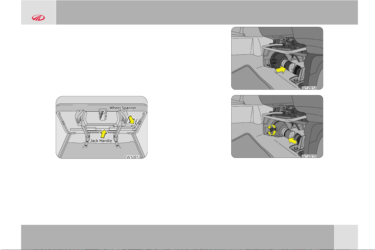
• placed in a pouch behind the 3rd row seat/seat back (for 8 seat
W12B13
W12B14
W12B15
— front facing, 7 seat — captain seat variants)
• under the RH jump seat (for 7/9 seat — side facing variants)
The wheel spanner and jack handle are:
• strapped to the 2nd row seat bottom (for 7/9 seat — side
facing variants)
• strapped to the 3rd row seat bottom (for 8 seat — front facing,
7 seat — captain seat variants)
GENERAL
The jack is located under the co-driver's seat. Rotate the jack
handle to reduce the jack height and lift the jack out.
© Copyright Mahindra & Mahindra Ltd. 012016
2.6.2 Spare Wheel Removal
The spare wheel is located below the floor at the rear end of the
vehicle. It is held in place by a securing nut underneath the rear
luggage compartment floor carpet.
2-13
Page 31

W12B16
W12B17
W12B18
W12B19
GENERAL
• Locate the flap covering the securing nut below the rear luggage
compartment floor carpet
• Loosen the securing nut counter clockwise with a wheel spanner
to winch down/lower the secured spare wheel to the ground
• Tilt the securing bracket and remove it out of the spare wheel
hub
• Remove/pull away the spare wheel
2-14
© Copyright Mahindra & Mahindra Ltd.012016
Page 32

2.6.3 Wheel Nut Loosening
3
1
4
2
5
W12B20
A
B
A B
W12B21
GENERAL
Wrap the tip of a screw driver with cloth, insert it near the lugs of
the wheel cap (if equipped) and pry the cap away from the wheel.
Do not try to pry off the wheel cap by hand alone. Take due care
in handling the wheel cap to avoid unexpected personal injury.
Always loosen the wheel nuts before raising the vehicle. Turn the
wheel nuts counter clockwise to loosen as per the sequence. To get
maximum leverage, fit the spanner to the nut so that the handle is
on the left side. Grab the spanner near the end of the handle and
push down on the handle. Be careful that the spanner does not slip
off the nut. Do not remove the nuts, but loosen them by one or two
turns.
Do not apply force with your legs (or stand) on the wheel
spanner while loosening/tightening the wheel nuts.
2.7 Jack Points
Front jack up point - On the chassis long member just behind the
front wheels.
Rear jack up point - Under the rear axle.
© Copyright Mahindra & Mahindra Ltd. 012016
2-15
Page 33

A
B
W12B22
RAISE
Max Limit
(Yellow Line)
LOWER
W12B23
GENERAL
Rear Jacking Points
A
Front Jacking Points
B
2.7.1 Jacking
Position the jack at the correct jacking point. Make sure the jack is
positioned on a level and solid ground. Ensure no one is in the
vehicle.
Block the wheel diagonally opposite the flat tyre to keep the vehicle
from rolling when it is jacked up. When blocking the wheel, place a
wheel block in front of one of the front wheels or behind one of the
rear wheels.
Flat Tyre
A
To raise the vehicle, insert the jack handle end along with the
extension into the jack and turn it clockwise with the jack handle. As
the jack touches the vehicle and begins to lift, re-check that it is
B Chock Blocks
properly positioned. Raise it high enough ensuring the spare wheel
can be installed, but not to raise up above the ‘yellow’ line.
Remember you will need more ground clearance when putting on
the spare tyre than when removing the flat tyre.
Make sure to set the jack properly in the jacking point. Raising
the vehicle with an improperly positioned jack will damage the
underbody of the vehicle or may allow the vehicle to fall off the
jack and cause personal injury.
• Use the jack only for lifting your vehicle during wheel
changing
• Do not raise the jack with someone in the vehicle
• When raising the vehicle, do not place any objects on top of
or underneath the jack
2-16
© Copyright Mahindra & Mahindra Ltd.012016
Page 34

• Raise the vehicle only high enough to remove and change
W12B24
the wheel
• Usable extended height of jack is up to the yellow line/mark.
Do not raise the jack above the yellow line.
• Follow jacking instructions
• Do not start or run the engine while your vehicle is
supported by the jack
Never get under the vehicle when the vehicle is supported by
the jack alone.
Remove the wheel nuts. Lift the flat tyre straight off and place it
aside. Roll the spare wheel into position and align the holes in the
wheel with the bolts. Lift up the wheel and get at least the top bolt
started through its hole. Wiggle the wheel and press it back over
the other bolts.
Re-install the wheel nuts with the tapered end inward and tighten by
hand. Press the wheel inward and tighten the wheel nuts further.
GENERAL
Never use oil or grease on the bolts or nuts. Doing so may lead
to over tightening of the nuts, wheel nut spanner slip, damage
the bolts and also may cause personal injuries. Also, nuts may
loosen and the wheels may fall off, which could cause a serious
accident. If there is oil or grease on any bolt or nut, clean before
installing wheel nuts.
Lower the vehicle completely and tighten the diagonally opposite
wheel nuts using the wheel nut spanner. Turn the jack handle
extension counter clockwise using the jack handle to lower the
vehicle, making sure the handle remains firmly fitted onto the jack
handle extension. Make sure the wheel spanner is securely
engaged over the nut. Tighten each nut a little at a time in the
diagonally opposite order as shown. Repeat the process until all the
nuts are tight. Do not use other tools or any additional leverage
other than your hands, such as a hammer, pipe or your foot.
© Copyright Mahindra & Mahindra Ltd. 012016
2-17
Page 35

3
1
4
2
5
W12B25
GENERAL
Put the wheel cap into position aligning the nozzle on the wheel to
the nozzle clearance on the wheel cover. Tap it firmly on the sides
with your hand to snap it into place.
Check the air pressure of the replaced tyre. If the pressure is lower
than recommended, drive slowly to the nearest service station and
inflate to the correct pressure. If it is too high, adjust it until it is
correct. Always reinstall the valve cap after checking or adjusting
tyre pressure. If the cap is not replaced, dirt and moisture could get
into the valve core and cause air leakage. If you lose a valve cap, buy
another and install it as soon as possible.
Improperly or loosely tightened wheel nuts are dangerous. The
wheel could wobble or come off. This could result in loss of
vehicle control and cause a serious accident. Always make sure
all the wheel nuts are properly/securely tightened to the
specified torque.
When lowering the vehicle, make sure all portions of your body
are clear off the vehicle as it is lowered to the ground. Have the
wheel nuts tightened with the torque spanner to 120 Nm, as
soon as possible after changing wheels.
If you have rotated, repaired, changed your tyres or changed
the wheel rims, check the wheel nuts are still tight after driving
about 1,000 kms (Torque 120 Nm).
2-18
2.7.2 Restore the Tools, Jack and Flat Tyre Securely
Restore the tools and jack back to their respective locations. Align
the spare wheel bracket to the centre hub of the wheel. Winch up
the flat tyre to the floor at the rear of the vehicle. Firmly tighten the
securing nut and put the floor carpet back. Double check to ensure
the tyre is snug against the rear floor of the vehicle. The spare
wheel bracket/cable may be damaged if the vehicle is driven with
the spare wheel loosely mounted.
© Copyright Mahindra & Mahindra Ltd.012016
Page 36

W12B26
W12B27
It is recommended to fix the flat tyre at the nearest tyre shop
and swap the spare wheel back. The wheel balance and
alignment differ from wheel to wheel which may lead to
difference in steering and braking.
GENERAL
© Copyright Mahindra & Mahindra Ltd. 012016
2-19
Page 37

GENERAL
2.8 Technical Specifications
Technical Specifications
ENGINE - mHawk CRDe - BSIV
Displacement/Cubic Capacity
Type 4 Stroke, Turbocharged, Common Rail Direct Injection Engine
Bore x Stroke 85.0 X 88.0 mm
No of Cylinders
Compression Ratio
Max. Engine Output (kW @ rpm) 88.26 ± 2% kW @ 4000 rpm
Max. Torque (Nm @ rpm) 280.0 Nm @ 1800 to 2800 rpm
CLUTCH
Type Single Plate, Dry Type, Hydraulic Actuation
TRANSMISSION
Type Manual, Synchromesh in all Forward Gears
No. of Gears
GEAR RATIOS
I 3.777 : 1
II 2.214 : 1
III 1.425 : 1
IV 1.00 : 1
V 0.791 : 1
Reverse 3.559 : 1
1997 cc
4 Inline
16.5:1
5 Forward, 1 Reverse
2-20
© Copyright Mahindra & Mahindra Ltd.012016
Page 38

Technical Specifications
TRANSFER CASE (4X4 ONLY)
Type
Ratio
Electric Shift
1 : 1 (High), 1 : 2.48 (Low)
AXLES
Front
Rear
2WD — Non-drive, Stub Axle
4WD — Full Floating, 4.3 : 1 (with Electric Disconnect)
Single Reduction Semi Floating Hypoid type
2WD – 4.3 : 1
4WD – 4.3 : 1
WHEELS & TIRES
Rim 6.5J x 17"
Tires
P235/65 R17 104H
STEERING
Type/Description Rack & Pinion, Power Assisted - Hydraulic
Turning Circle Diameter
10.8 m for 2WD
11.3 m for 4WD
SUSPENSION
Front
Rear
Shock Absorbers
Double Wish-bone type IFS with Anti Rollbar
Multi Link Coil Spring Suspension with Anti Rollbar
Hydraulic, Double Acting, Telescopic
BRAKES
Service Brake
Front
Hydraulic, Vacuum Assisted Servo, Front Disc, Rear Drum, with ABS & EBD (if equipped)
Ventilated Disc and Caliper Type
GENERAL
© Copyright Mahindra & Mahindra Ltd. 012016
2-21
Page 39

GENERAL
Technical Specifications
Rear
Parking Brake Internal Expanding with Auto Adjuster on Rear Wheels, Hand Lever and Cable type
Drum type, Internally Expanding with Auto Adjuster
FUEL
Fuel Capacity
60 liters
ELECTRICAL SYSTEM
System Voltage
Battery
12V
65 Ah OPT 72Ah
2-22
© Copyright Mahindra & Mahindra Ltd.012016
Page 40

W12B28
AT
TENTI
ON
W12B29
GENERAL
2.9 Vehicle Identification Number (VIN)
Vehicle Identification Number (VIN) is the legal identity of your
vehicle. The vehicle identification number is stamped on the VIN
plate riveted on to the top face of the cross member under the
hood of the vehicle. The engine number is also stamped on the
same plate.
2.10 Engine Number
The engine number is punched on the LHS face of the crankcase
adjacent to the water pump. The engine number is also stamped on
the VIN plate near the bonnet release lever.
© Copyright Mahindra & Mahindra Ltd. 012016
2-23
Page 41

Page 42

W12C01
A B C D E
FGHJ IKLMN
VEHICLE OVERVIEW
3 VEHICLE OVERVIEW
3.1 Front Overview
A Hood
B Front Wiper
C Windshield
D Antenna
E Ski Rail
F ORVM
G Footstep
H Side Repeater
I Position Lamp
J Low Beam / Projector Lamp
K Fog Lamp
#
L High Beam
M Turn Indicator
N Front Bumper
# if equipped
#
#
© Copyright Mahindra & Mahindra Ltd. 012016
3-1
Page 43

W12C02
L
VEHICLE OVERVIEW
3.2 Rear Overview
A Rear Windshield
B High Mounted Stop Lamp
C Rear Windshield De-mister
D Rear Wiper
#
E Rear Bumper
F Rear Footstep
G Rear Registration Plate
H Rear Reflector
I Rear Door
J Reversing Lamp
K Rear Park Lamp/Brake Lamp
L Rear Turn Signal Lamp
# if equipped
#
#
3-2
© Copyright Mahindra & Mahindra Ltd.012016
Page 44

3.3 Instrument Panel Overview
W12C05
A
M
Q
R
W
V
T
S
U
B C F G JI K LHED
N
O
P
VEHICLE OVERVIEW
Side Vent
A
Side Defrost Vent
B
Passenger Air-bag
C
HVAC Controls
D
Infotainment System
E
Center Vents
F
Steering Controls — Audio
G
Instrument Cluster
H
Horn Pad/Driver Air-bag
I
Steering Wheel
J
Light Stalk
K
Steering Controls — Cruise
L
Pedals — Clutch, Brake and Accelerator
M
Parking Brake
N
4WD Switch
O
Rear AC Vents
P
Can Holder
Q
Rear Power Socket
R
Bottle Holder
S
Front Power Socket
T
Transmission Lever
U
Auto Head lamp / Wipe Switches
V
W
# if equipped
Glove Box
#
#
#
#
#
© Copyright Mahindra & Mahindra Ltd. 012016
3-3
Page 45

Page 46

4 INSTRUMENT CLUSTER OVERVIEW
H G F
W12D13
A
E
DC
B
4.1 Instrument Cluster - Type 1
INSTRUMENT CLUSTER OVERVIEW
A
B
C
D
© Copyright Mahindra & Mahindra Ltd. 012016
Tachometer / RPM Gauge
Temperature Gauge
Trip Meter
Fuel Gauge
E
Speedometer
F Mode Button
G Odometer
H Set Button
4-1
Page 47

A
I GH F
W12D14
B
D
EC
INSTRUMENT CLUSTER OVERVIEW
4.2 Instrument Cluster - Type 2
4-2
A
B
C
D
E
Tachometer / RPM Gauge
Temperature Gauge
Trip Meter
Fuel Gauge
Speedometer
F Mode Button
G Odometer
H Gear Indicator
I Set Button
© Copyright Mahindra & Mahindra Ltd.012016
Page 48

4.3 Warning Lamps Overview
ENGINE !
Left Turn Indicator
Right Turn Indicator
Headlamp High Beam
Malfunction Lamp (OBD)
Check Engine Lamp
Door Ajar Lamp
High Temperature Lamp
Low Oil Pressure Lamp
Park/Low Brake Fluid Lamp
Security Lamp
Battery Charge Lamp
Seat Belt Warning Lamp
Parking Lamp
Water in Fuel Warning Lamp
Low Fuel Warning Lamp
4WD High Lamp
4WD Low Lamp
Glow Plug Lamp
Airbag Warning Lamp
ABS Warning Lamp
4WD
LOW
T
o know more about warning & telltale lamps, download the handy “Scorpio” app
from Google playstore or Appstore
INSTRUMENT CLUSTER OVERVIEW
© Copyright Mahindra & Mahindra Ltd. 012016
4-3
Page 49

ENGINE !
Left Turn Indicator
Right Turn Indicator
Headlamp High Beam
Malfunction Lamp (OBD)
Check Engine Lamp
Door Ajar Lamp
High Temperature Lamp
Low Oil Pressure Lamp
Park/Low Brake Fluid Lamp
Security Lamp
Battery Charge Lamp
Seat Belt Warning Lamp
4WD High Lamp
Parking Lamp
4WD Low Lamp Front Fog Lamp
Water in Fuel Warning Lamp
Airbag Warning Lamp TPMS Warning Lamp Cruise Control Indicator
ABS Warning Lamp
Low Fuel Warning Lamp
4WD
LOW
T
o know more about warning & telltale lamps, download the handy “Scorpio” app
from Google playstore or Appstore
Glow Plug Lamp
INSTRUMENT CLUSTER OVERVIEW
4.4 Warning Lamps
The phenomenon of warning lamps flashing momentarily when ignition is turned ON is called pre-check. This is self check done by the cluster
at every ignition ON.
4-4
© Copyright Mahindra & Mahindra Ltd.012016
Page 50

ENGINE !
INSTRUMENT CLUSTER OVERVIEW
Symbol Warning Lamp/Tell Tale Lamp Pre-check Lamp Status Action/Remarks
Either one of below conditions:-
Parking Brake ON/Brake Fluid
Low Warning Lamp
Left Turn Indicators No
Water in Fuel Filter Warning
Lamp
Security Lamp
Check Engine Lamp
Yes
Yes
No
For about 3 sec
1) Park brake might be engaged
Continuously ON
2) Brake fluid level might be low
Contact Authorized Mahindra Dealer immediately for
assistance if the lamp is not turning OFF even after checking
the above conditions
Indicates left turn lamp is blinking
Slow or Fast Blinking
Slow Blinking: Normal operation
Fast Blinking: One /more left turn lamp bulb has fused. Have
the bulb replaced
Continuously ON Indicates water in fuel filter. Drain the water from filter or
contact an Authorized Mahindra Dealer for assistance
Slow Blinking: Vehicle armed and Immobilizer system active
Slow or Fast Blinking
Fast Blinking: Once the ignition is turned OFF, security lamp
will blink at fast rate frequency indicating vehicle is secured
against unauthorized start of engine
Continuously ON or
Blinking
There is a potential malfunction in the engine system, contact
an Authorized Mahindra Dealer immediately
© Copyright Mahindra & Mahindra Ltd. 012016
4-5
Page 51

INSTRUMENT CLUSTER OVERVIEW
Symbol Warning Lamp/Tell Tale Lamp Pre-check Lamp Status Action/Remarks
High Coolant Temperature
Warning Lamp
Right Turn Indicators
Head Lamp High Beam Indicator
ABS Warning Lamp
Airbag Warning Lamp
Cruise Control Indicator Yes
Door Ajar Warning Lamp
No
No
No
For about 3 sec.
For about 3 sec.
No
Continuously ON or
Blinking
Engine temperature very high. Contact an Authorized
Mahindra Dealer immediately
Indicates right turn lamp is blinking
Slow or Fast Blinking
Slow Blinking: Normal operation
Fast Blinking: One /more turn signal lamp bulb has fused.
Have the bulb replaced
Continuously ON
Continuously ON
Continuously ON
Continuously ON
Indicates head lamp high beam is ON
Indicates malfunction of the ABS system. Contact an
Authorized Mahindra Dealer immediately
Indicates malfunction of the airbag system. Contact an
Authorized Mahindra Dealer immediately
Indicates vehicle is in cruise mode
Continuously ON Indicates one or more doors are open
4-6
© Copyright Mahindra & Mahindra Ltd.012016
Page 52

4WD
LOW
INSTRUMENT CLUSTER OVERVIEW
Symbol Warning Lamp/Tell Tale Lamp Pre-check Lamp Status Action/Remarks
Front Fog Lamp Indicator
Seat Belt Warning Lamp
Low Fuel Warning Lamp
TPMS Warning Lamp
4WD High
4WD Low No
Malfunction Lamp (OBD)
No
No
No
No
No
Continuously ON till
Engine Starts
Continuously ON Indicates front fog lamp is ON
Indicates driver seat belt not fastened. If tell tale is not turning
Continuously ON
OFF even after fastening the driver seat belt, contact an
Authorized Mahindra Dealer for assistance
Continuously ON
Continuously ON or
Blinking
The fuel level in the fuel tank is low. Re-fuel immediately to a
avoid empty tank
Indicates low tyre pressure or possible malfunction in TPMS.
Refer to the TPMS section in the FEATURES AND CONTROL/
WHEELS AND TIRES chapter for further details
Continuously ON Indicates transmission is in 4WD High
Continuously ON
Continuously ON
Indicates transmission is in 4WD Low
There is a potential malfunction related to emission control
system, contact an Authorized Mahindra Dealer immediately
© Copyright Mahindra & Mahindra Ltd. 012016
4-7
Page 53

INSTRUMENT CLUSTER OVERVIEW
Symbol Warning Lamp/Tell Tale Lamp Pre-check Lamp Status Action/Remarks
Battery Charging Warning Lamp
Low Engine Oil Pressure
Warning Lamp
Glow Plug Indicator
Continuously ON till
Engine Starts
Continuously ON till
Engine Starts
For about 2 seconds
Continuously ON Indicates malfunction in the charging system. Contact an
Authorized Mahindra Dealer for assistance
Continuously ON Indicates engine oil pressure is low. Check oil level and top-up
or contact an Authorized Mahindra Dealer for assistance
Continuously ON
Indicates a malfunction in the starting system. Contact an
Authorized Mahindra Dealer immediately
4-8
© Copyright Mahindra & Mahindra Ltd.012016
Page 54

W12E01
25
o
SEATS AND SEAT BELTS
5 SEATS AND SEAT BELTS
5.1 Driver seat
5.1.1 Sitting in the Correct Position
Follow the tips below for a comfortable and safe journey;
• Sit in an upright position with the base of your spine pressed
against the seat back
• Adjust the head restraint as close as possible to the above
specified position, with the top of the head restraint even with
the top of your head
• Maintain sufficient distance between yourself and the steering
wheel. Maintain at least a ten inch (10") distance from the
centre of the steering wheel to your chest
• The top curve of the steering wheel should align with your chin
for ideal road visibility
• Adjust your seat and seat back angle such that your wrists rest
on top of the steering wheel freely
• Ensure your legs are in a bent position while fully depressing the
clutch pedal
The seat should be adjusted while still maintaining control of the
foot pedals, steering wheel and your view of the instrument panel
controls.
Never adjust the driver's seat while the vehicle is in motion. The
seat may unexpectedly move and cause the driver to
unintentionally operate the accelerator or brake, or turn the
steering wheel, causing loss of control of the vehicle, an
accident or serious personal injury. Adjust the driver's seat only
when the vehicle is not in motion.
Never put objects under the seats. They may interfere with the
seat-lock mechanism or unexpectedly activate the seat position
adjusting lever, causing the seat to suddenly move, resulting in
loss of control of the vehicle, an accident or serious personal
injury.
While adjusting the seat, do not put your hands under the seat
or near the moving parts. This may lead to injuries.
© Copyright Mahindra & Mahindra Ltd. 012016
5-1
Page 55

W12E02
W12E03
SEATS AND SEAT BELTS
5.1.2 Front Seat Slide
Move the seat forward or backward by lifting the adjustment lever
located under the seat front and release once the desired position
is reached.
While adjusting the seat, make sure the latch engages fully and
the seat is locked firmly in the desired position. An unlocked
seat may move in a sudden stop or collision, causing injury to
the person in that seat. Push and pull on the seat to be sure it
is locked.
5.1.3 Front Seat Recline
To adjust the seat back, lift the lever located on the outboard side of
the seat, lean back, and release the lever at the desired position. To
return the seat back, lift the lever, lean forward, and release the
lever.
The seat belts provide maximum protection in a frontal or rear
collision when the occupants are sitting up straight and well
back in the seats. If you are reclined, the lap belt may slide past
your hips and apply restraint forces directly to the abdomen, or
the shoulder strap may contact your neck. The more the seat is
reclined, the greater the risk of serious injury.
5-2
© Copyright Mahindra & Mahindra Ltd.012016
Page 56

W12E29
5.2 Head Restraint
SEATS AND SEAT BELTS
When returning a extremely reclined seat back to its upright
position, make sure you support the seat back while operating
the lever.
5.1.4 Driver Seat Height Adjust (if equipped)
Lift/Push the seat height adjustment lever located on the outboard
side of the driver seat to raise/lower the seat. Adjust the seat
height such that you can depress the clutch pedal completely.
It is recommended to adjust the seat height only when the
vehicle is stationary.
5.2.1 Adjustable Head Restraint
The head restraint comprises of the padded portion which contacts
your head and is inserted/locked in receptacles on the top of the
seat back.
Your vehicle seats are equipped with head restraints which are
vertically adjustable. The purpose of these head restraints is to help
limit head motion in the event of rear collision.
Always align top of the head restraint with the top of your head or
as close to it as possible. To raise the head restraint, press the lock
knob and pull the restraint up. To lower the head restraint, press
the lock knob and push the head restraint down.
© Copyright Mahindra & Mahindra Ltd. 012016
5-3
Page 57

W12E07
SEATS AND SEAT BELTS
5.2.2 Removing Seat Head Restraint
The head restraint can be pulled out completely by depressing the
locking button while pulling the restraint out.
5.2.3 Installing Seat Head Restraint
Align the head restraint shafts over the holes on the seat top and
push the restraint straight down till you hear the lock click.
Keep the seat back as upright as possible so the headrest is
behind, not beneath, and almost touching your head.
Never drive with the head restraints not properly adjusted,
head restraints removed or inserted in a flipped condition. With
no support behind your head, your neck could be seriously
injured in a collision.
Head restraints are provided for the front row and second row
outboard occupants.
5.3 Second Row Bench Seat
Loading cargo on the seats is dangerous. The cargo becomes a
projectile that could hit and injure passengers in a sudden stop
or collision. Cargo should always be kept on the floor.
Seat Recline
The second row seat back can be reclined forward/backward for
maximum comfort.
To change the second row seat back angle, lean forward slightly
while raising the recline levers on either side of the seat, lean back
to the desired position and release the recline lever. Make sure the
recline lever returns to its original position and the seat back is
locked in place by attempting to push it forward and backward.
5-4
© Copyright Mahindra & Mahindra Ltd.012016
Page 58

When returning the rear-reclined seat back to its upright
W12E08
W12E09
position, make sure you support seat back while operating the
lever.
Seat Folding
The second-row seat can be flipped forward to provide more cargo
space.
1. Lower the second-row seat head restraint to the lowest
position
2. Recline and fold down the seat back (refer previous section for
reclining the seat back)
3. Pull the strap behind the seat to unlock and lift the seat base
to vertical position
SEATS AND SEAT BELTS
4. To keep the seat in vertical folded position, hook the seat to the
front seat head restraint rod with the holding strap kept in the
small pocket in the seat bottom. Tighten the holding strap to
securely hold the seat to the head restraint
Unhook the strap, when the seat needs to be unfolded and put the
strap back in the pocket. Swing the whole seat-back down to lock
the latch. Ensure the seat is locked.
A seat not secured with a holding strap is dangerous. Ensure
that the stowed seats are secured with the holding straps. The
holding strap and hook is kept in the pocket under the seat.
Return the seat back to its position in one continuous motion to
securely lock the seat and in turn avoiding the seat flipping
forward suddenly leading to injuries. If this happens, release the
seat lock by pulling the lever and repeat the procedure. Be
cautious when placing your hands around the seat anchors.
© Copyright Mahindra & Mahindra Ltd. 012016
5-5
Page 59

W12E33
W12E34
SEATS AND SEAT BELTS
You could pinch your hands or fingers between the seat anchor
and the seat. Hold the edge of the seat when lowering it into
place. Never place your hands between the seat anchor and
the seat.
5.4 Second Row Seat 60:40
The second row seat has a optional 60:40 split with individual
folding option.
Seat Slide
Lift the seat lock lever under the respective seat and push/pull on
the seat to adjust as per convenience.
Seat Recline & Double Fold
Follow the below steps to recline and double fold the seat.
1. To change the seat back angle, lean forward slightly while
raising the recline lever on outboard side of the seat, lean back
to the desired position and release the recline lever. Make
sure the recline lever returns to its original position and the
seat back is locked in place by attempting to push it forward
and backward. To fold, lower the seat back completely down
5-6
© Copyright Mahindra & Mahindra Ltd.012016
Page 60

W12E31
W12E32
W12E30
W12E10
SEATS AND SEAT BELTS
2. Unlock the seat by the seat unlock lever located on the
outboard side under the seat. Alternatively, third row
passengers can unlock the seat by the strap behind the
second row seat
© Copyright Mahindra & Mahindra Ltd. 012016
3. Stack the seat up vertically against the first row seat. To keep
the seat in vertical folded position, hook the seat to the front
seat head restraint rod with the holding strap kept in small
pocket in the seat bottom. Tighten the holding strap to
securely hold the seat to the head restraint
5.5 Second Row Captain Seat Arrangement
5-7
Page 61

W12E35
RH
W12E11
W12E36
SEATS AND SEAT BELTS
The second row captain seat is similar to that of the front
passenger seat and provides adequate space and enhanced
comfort. You can recline or fold the individual seats as required
which will help in ingress to the third row front facing seat.
Seat Recline
To change the seat back angle, lean forward slightly while raising
the recline lever on outboard side of the seat, lean back to the
desired position and release the recline lever. Make sure the recline
lever returns to its original position and the seat back is locked in
place by attempting to push it forward and backward.
Seat Fold
1. Lower the seat back down completely (refer to previous
section for seat recline)
2. Unlock the seat by the seat unlock lever located on the
outboard side under the seat. Alternatively, third row
passengers can unlock the seat by the strap behind the
second row captain seat
5-8
© Copyright Mahindra & Mahindra Ltd.012016
Page 62

W12E37
3. Lift the seat up and stack it vertically
W12E12
W12E13
4. To keep the seat in vertical folded position, hook the seat to the
front seat head restraint rod with the holding strap kept in the
small pocket in the seat bottom. Tighten the holding strap to
securely hold the seat to the head restraint
SEATS AND SEAT BELTS
5.6 Foldable Arm-Rests
Front and middle seats (Captain Seats only) are provided with
individual foldable arm rests.
© Copyright Mahindra & Mahindra Ltd. 012016
5-9
Page 63

W12E14
W12E15
W12E16
SEATS AND SEAT BELTS
5.7 Third Row Seats
5.7.1 Third Row Front Facing Type (if equipped)
The third row seats have a centre armrest and can be reclined or
folded as required to maximise cargo space. Access to or exit from
the third row seat is possible by completely double folding the
second row seat.
Refer to the previous sections for reclining of second row
seats.
To recline the third row seat, pull the seat back recline lever on the
outboard side of the seat and fold down the seat back flat. To lift/
unlock the seat, press the seat locking levers on either side of the
seat (from behind) and lift the seat.
5.7.2 Third Row Side Facing Type (if equipped)
5-10
© Copyright Mahindra & Mahindra Ltd.012016
Page 64

W12E18
W12E19
The third row side facing jump seats can be folded to maximise
cargo space.
• Swing the seat cushion fully up
• Fold the seat leg completely down
• Secure the seat by the Velcro strap provided on the back of the
seat cushion
SEATS AND SEAT BELTS
5.8 General Warnings and Instructions- Seat Belts
At least once each month, inspect the seat belt webbing for any
cuts, tears, or other signs of wear (such as fraying along the
edges). Also inspect the anchors, retractors, and buckles to be
sure they are tight and operational.
• All occupants, including the driver, should always wear their seat
belt no matter how short the trip in order to minimize the risk of
severe injury in the event of a crash. In an accident, an un-belted
passenger becomes a projectile, and can cause serious injury to
himself or another passenger.
• In a rollover crash, an un-belted person is significantly more likely
prone to Injury than a person wearing a seat belt
• In order to be properly buckled, you must always sit up straight
and keep your feet on the floor in front of you. The lap part must
be worn low and tight across your hips, just touching the top of
your thighs. While fastening the seat belt, the shoulder strap of
the seat belt must pass over your chest and top of your
shoulder. It must never touch your neck, face, the side of your
shoulder, arm, or pass under your arm. The belt must always be
flat against your body and not twisted in any way. Nothing, such
as an arm rest, a pocketbook, or any external objects should be
between you and the seat belt.
will reduce the protection in an
• Seat belts should be adjusted as tightly as possible, consistent
with comfort to properly secure the wearer in the seat.
Improper wearing
accident.
of a seat belt
© Copyright Mahindra & Mahindra Ltd. 012016
5-11
Page 65

SEATS AND SEAT BELTS
• The seat belts provided for your vehicle are designed for people
of adult size, must be properly used and maintained.
• For usage of adult seatbelt to secure children refer to section on
manual for child seat positions and use a child restraint systems
• Passengers should not move out of or change seats while the
vehicle is moving. A passenger who is not wearing a seat belt
can be thrown against the inside of the vehicle, against other
occupants, or out of the vehicle during a crash or emergency
stop
• Do not use any accessories on seat belts or modify in any way
the seat belt system. Devices claiming to improve occupant
comfort or reposition the seat belt can reduce the protection
provided by the seat belt and increase the chance of serious
injury in a crash
• An accident or emergency stop, can damage your seat belt
system, even if the accident is “minor”. Please have your
Authorized Mahindra Dealer inspect the seat belt system after
an accident
• Please be aware that any unsecured item in your vehicle, such
as your pet, unsecured child restraint system, or a laptop, can
become a projectile in the event of an accident or sudden stop,
causing injuries to occupants in the vehicle
Never use a damaged seat belt system. A damaged seat belt
will not provide protection in an accident, resulting in serious
injury.
• Seat belt systems can be prone to abuse. They are not
indestructible. They must be handled with care to avoid damage
• Keep the belts clean and dry. Belt retraction may become
difficult if the belts and webbing are soiled. If they need cleaning,
use a mild soap solution or lukewarm water. Never use bleach,
5-12
© Copyright Mahindra & Mahindra Ltd.012016
Page 66

SEATS AND SEAT BELTS
dye, or abrasive cleaners. These chemicals will severely weaken
the belts
• Retractors in 3-point type seat belts retract the seat belts when
not in use. The inertia lock and coil spring allow the belts to
remain comfortable on users during normal driving. During
accidents or abrupt stops, inertia locks restrict the sudden
forward movement of the wearer
Seat Belts - Patients
Persons with serious medical conditions should also wear a seat
belt. Consult your doctor for specific recommendations before
travel.
Seat Belts - Pregnant Women
Pregnant women must also wear seat belts. Consult your doctor
for specific recommendations.
The lap belt should be worn snugly and as low as possible over the
hips. The shoulder belt should be worn across your shoulder, but
never across the stomach area. When worn properly, the seat belt
will protect both the mother and the foetus in an accident or
emergency stop.
A pregnant woman should never wear the seat belt across the
stomach area. This could lead to serious injuries to the foetus
and/or the pregnant mother.
Never wear twisted seat belts. Excessive forces will be
transferred from the belt to the wearer, in a collision, resulting
in serious personal injury.
Each seat belt is meant for use by one person only. Using one
seat belt for more than one person at a time is dangerous. The
seat belt will not be able to spread the impact forces properly
leading to serious injuries.
Never put a belt around a child being carried on the occupant's
lap. This could lead to serious injuries.
© Copyright Mahindra & Mahindra Ltd. 012016
5-13
Page 67

SEATS AND SEAT BELTS
Seat Belt Usage is Necessary to:
• Reduce the possibility of being thrown from your vehicle
• Reduce the possibility of injuries to lower body and legs during an
accident
• Hold the driver in a position which allows better control of the
vehicle
Children who are too large for child restraint systems should always
occupy the rear seat and use the vehicle seat belts. The lap portion
should be fastened snug on the hips and as low as possible and the
shoulder strap should be across the child's shoulder, not the neck
or face. If you are unable to position the strap across the child's
shoulder, the child should remain in a booster seat. Frequently
check the seat belt to be sure it remains snug and in position. A
squirming child could cause the seat belt to come out of position.
5.9 Child Restraint System (CRS)
Always secure a child in a proper Child Restraints System in
accordance with age and size of the child as recommended by the
child restraint system manufacturer. Be sure to follow the Child
5-14
© Copyright Mahindra & Mahindra Ltd.012016
Page 68

Restraint System (Child seat) manufacturer’s instructions for seat
belt routing.
Do not allow children to stand up or kneel on either the rear or
the front seats. An unrestrained child could suffer serious
injuries during emergency braking or collision.
Legend:
U — Suitable position for using universal child restraint system
using seat belt and buckles marked with ‘ C R S ’.
Ø — Not Suitable position for using child restraint system using seat
belt.
Mass Group Weight of Child (kg)
Group 0
0–10
Group 0+ upto 13
Group 1
Group 2
Group 3
9–18
15–25
22–36
Fitting the child
restraints system using
seat belt
Rear-facing child
restraint system on the
outboard 2
n
d
row seats
using seat belt.
Forward-facing child
restraint system on the
outboard 2
n
d
row seat
using seat belt.
SEATS AND SEAT BELTS
© Copyright Mahindra & Mahindra Ltd. 012016
5-15
Page 69

Page 70

SUPPLEMENTAL RESTRAINT SYSTEM (SRS) (if equipped)
6 SUPPLEMENTAL RESTRAINT SYSTEM (SRS) (if equipped)
6.1 Airbags
Your vehicle has the following airbags:
• A frontal airbag for the driver
• A frontal airbag for the front passenger (if equipped)
Airbags are located in:
• The steering wheel hub
• The passenger side instrument panel
They are indicated by “SRS AIRBAG” embossed on the covers.
An airbag is not designed to deploy in every type of crash.
Depending on the type of accident or impact, the front airbags
independently deploy thereby protecting the occupants. It is not
necessary that ALL the airbags deploy during an accident.
To minimize the risk of severe injury in the event of a crash, every
passenger must always wear their seat belt (see the chapter on
Seat Belts in this manual). The airbags inflate very quickly with great
force. Do not position any part of your body too close to a airbag,
you or especially children could be seriously injured/killed by a
deploying airbag.
6.2 Introduction
The Supplemental Restraint System (SRS) includes airbags, pretensioners and ECU. The airbags are designed to provide further
protection to the vehicle occupants in addition to the primary
protection provided by the seat belts and seat belt pre-tensioners.
The primary components of the system are the sensors which
measure the crash severity. In the event of a significant frontal
impact, the SRS airbags inflate to work in conjunction with the seat
belts and help reduce injuries mainly to the driver's or front
passenger's head/chest.
Seat belts are the primary restraint system in the vehicle. An
airbag provides supplemental protection in addition to the seat
belts.
All occupants, including the driver, should always wear their
seat belts irrespective of presence of airbags to minimize the
risk of severe injury in the event of a crash.
Airbags are more effective in reducing injuries when the seat
belts are worn.
6.2.1 Driver and Front Passenger Air Bag
Your vehicle is equipped with a Supplemental Restraint System
(Airbag) and lap/shoulder belts at both the driver and front
© Copyright Mahindra & Mahindra Ltd. 012016
6-1
Page 71

SUPPLEMENTAL RESTRAINT SYSTEM (SRS) (if equipped)
passenger seating positions. The indications of the system's
presence are the letters “SRS AIR BAG” embossed on the airbag
pad cover in the steering wheel and the passenger's side front
panel pad above the glove box.
The SRS is designed to deploy the front airbags only when an
impact is sufficiently severe and when the impact angle is less than
± 30° from the forward longitudinal axis of the vehicle.
Front airbags are not intended to deploy in side-impact, rear impact
or rollover crashes. In addition, front airbags will not deploy in
frontal crashes which are below the prescribed deployment
threshold where risk of serious injuries is low.
Do not place any objects over the airbag or between the airbag
and yourself.
6.2.2 Airbag System Malfunction Lamp
Airbags do not require any regular maintenance of
service. The airbag system malfunction lamp
illuminates when the ignition is ON, and it turns OFF
after about two seconds as self check confirming
normal operations of airbag system and malfunction lamp.
This lamp monitors airbag sensor assembly, airbag sensors,
indicator lamp, seat belt pre-tensioner assemblies, inflators,
interconnecting wiring and power sources.
If either of the following conditions occur, there is a malfunction of
the airbags or seat belt pre-tensioner. Immediately contact your
Mahindra Dealer.
• The lamp does not glow when the ignition is switched ON or
glows beyond six (6) seconds after switching the ignition ON
• The lamp comes ON at any other time, even briefly
6-2
© Copyright Mahindra & Mahindra Ltd.012016
Page 72

SUPPLEMENTAL RESTRAINT SYSTEM (SRS) (if equipped)
• The lamp comes ON intermittently
Never make any modifications to your vehicle which could affect
the performance of your airbag system. In particular, changes
to the vehicle frame, bumpers, bull bar, front fenders, ride
height, suspension, seat belts, interior trim, seats or steering
wheel (especially covers, pads or other trim), could prevent
proper deployment of the airbag. If you need to make any
modifications to accommodate any disability you may have,
please contact your Authorized Mahindra Dealer.
Never try to open or strike the airbag cover. If the airbag cover
is cracked or damaged in any way, the airbag may not function
as intended. Take the vehicle to an Authorized Mahindra Dealer.
Even if the airbags do not deploy during an accident, take your
vehicle to an authorized Mahindra Dealer for a thorough inspection
of the airbag and seat belt systems, no matter how minor the
accident. The airbag system could have been damaged, and may
not work as intended in the future, resulting in serious injury.
6.2.3 Airbag Inflation/Deployment
The airbag sensors constantly monitor the forward deceleration of
the vehicle. If an impact results in a forward deceleration beyond
the designed threshold level, the system triggers the airbag
inflators. This initiates a chemical reaction which quickly fills the
airbags with non-toxic gas.
Upon deployment, tear seams molded directly into the pad covers
separate under pressure from the expansion of the airbags.
Further opening of the covers allows full inflation of the airbags. A
fully inflated airbag, in combination with a properly worn seat belt,
slows the driver's or the passenger's forward motion, reducing the
risk of head and chest injury.
After complete inflation, the airbag immediately starts deflating,
enabling the driver to maintain forward visibility and the ability to
maneuver or operate other controls.
Deployment of the airbags happen in a fraction of a second,
producing a loud noise releasing a ‘white smoke’ and residue along
with a non-toxic gas. This does not indicate a fire. This smoke may
remain inside the vehicle for some time, and may cause some
minor irritation to the eyes, skin or breathing. Be sure to wash off
any residue with soap and water as soon as possible to prevent any
potential skin irritation. If you can safely exit the vehicle, you should
do so immediately.
• Do not modify, remove, strike or open the seat belt pretensioner assemblies, airbag sensor or surrounding area or
wiring. Failure to follow these instructions may prevent them
from activating correctly, cause sudden operation of the
system or disable the system, which could result in serious
injury
© Copyright Mahindra & Mahindra Ltd. 012016
6-3
Page 73

SUPPLEMENTAL RESTRAINT SYSTEM (SRS) (if equipped)
• Parts of the airbag module (steering wheel hub, airbag cover
and inflator) may be hot for several minutes after
deployment. The airbags inflate only once
• Do not cover the steering wheel, instrument panel, seats
with any object (e. g. dash panel covers, seat covers) which
may prevent the airbags from inflating properly
• The airbags inflate with considerable force. While the
system is designed to reduce serious injuries, primarily to
the head and chest, it may also cause other, less severe
injuries to the face, chest, arms and hands. These are
usually in the nature of minor burns or abrasions and
swelling, but the force of a deploying airbag can also cause
more serious injuries, especially if an occupant's hands,
arms, chest or head is in close proximity to the airbag
module at the time of deployment. Sit straight and well back
into the seat. Move your seat as far back as practical to
allow room for airbag inflation, while still allowing you to
properly operate/drive the vehicle
The front passenger should never sit on the edge of the seat,
stand near the glove compartment, rest feet or other parts of
the body on the dashboard when the vehicle is moving.
The driver or front passenger who is too close to the steering
wheel or dashboard can be seriously injured during airbag
deployment.
• The driver must sit as far back as possible from the steering
wheel while still maintaining control of the vehicle
• The front passenger must sit as far back as possible from
the dashboard
• Sitting improperly or out of position can cause occupants to
be shifted too close to a deploying airbag, strike the interior
structure or be thrown from the vehicle resulting in serious
injury
6-4
© Copyright Mahindra & Mahindra Ltd.012016
Page 74

• Always sit upright with the seat back in an upright position,
on the seat cushion centre with your seat belt on, legs
comfortably extended and your feet on the floor
• All vehicle occupants must be properly restrained using the
seat belts
SUPPLEMENTAL RESTRAINT SYSTEM (SRS) (if equipped)
• All infants and children must be placed in the rear seat of
the vehicle in a child restraint seat and be properly
restrained by seat belts
• Front airbags can injure occupants improperly positioned in
the front seats
• Even with airbags, improperly belted and un-belted
occupants can be severely injured when the airbag inflates.
Always follow the precautions about seat belts, airbags and
occupant safety contained in this manual
• Do not modify the front seats. Modification of the front seats
could interfere with the operation of the supplemental
restraint system or side impact airbags
• Do not place items under the front seats. Placing items
under the front seats could interfere with the operation of
the supplemental restraint system sensing components and
wiring harnesses
© Copyright Mahindra & Mahindra Ltd. 012016
6-5
Page 75

SUPPLEMENTAL RESTRAINT SYSTEM (SRS) (if equipped)
6.2.4 Child Restraint and Airbag
Never place a rear-facing child restraint in the front passenger’s
seat. If the airbag deploys, injuries to the child may be fatal..
In addition, do not place front-facing child restraints in the front
passenger’s seat either. If the front passenger airbag inflates, it
could cause serious or fatal injuries to the child.
Extreme Hazard! Do not use a rear facing child restraint on a
seat protected by an airbag in front of it!
Never put a child restraint in the front passenger’s seat. If the
front passenger airbag inflates, it can cause serious or fatal
injuries.
Never hold an infant or child on your lap. The infant or child
could be seriously injured in the event of a crash. All infants and
children should be properly restrained in appropriate child
safety seats or seat belts in the rear seat.
Install the child restraint system on the rear outboard seats,
and securely lock the child restraint system in position.
Always Buckle Children (ABC) in the back seat. It is the safest
place for children of any age to ride.
6.2.5 Airbag Deployment
The images shown in this section are for illustrative purpose
only. They may not look like your model/variant or vehicle.
Front Air bag’s
Front air bags are designed to inflate in a frontal collision depending
on the intensity, speed or angles of impact of the front collision.
6-6
© Copyright Mahindra & Mahindra Ltd.012016
Page 76

Airbag Non-deployment
Impacts below a pre-determined threshold level may not cause the
airbag’s to deploy in the following cases:
•
Collision with Utility Poles or Trees -
SUPPLEMENTAL RESTRAINT SYSTEM (SRS) (if equipped)
Air bags may not inflate if the vehicle collides with objects such
as utility poles or trees, where the point of impact is
concentrated to one area and the full force of the impact is not
delivered to the sensors.
•
Under-ride Situations -
Running under a truck's tail gate may not provide the
decelerations necessary for airbag deployment. Just before
impact, drivers often brake heavily. Such heavy braking lowers
the front portion of the vehicle causing it to “ride” under a vehicle
with a higher ground clearance. Air bags may not inflate in this
“under-ride” situation where deceleration forces that are
detected by sensors may be significantly reduced by such
“under-ride” collisions.
© Copyright Mahindra & Mahindra Ltd. 012016
Rear-end Collisions -
Frontal air bags are not designed to inflate in rear collisions,
where occupants are moved backward away from the airbags by
6-7
Page 77
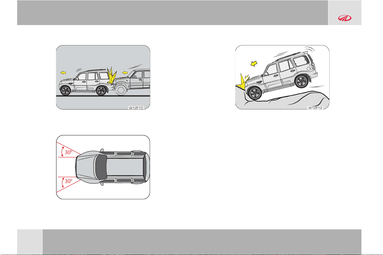
SUPPLEMENTAL RESTRAINT SYSTEM (SRS) (if equipped)
the force of the impact. In this case, inflated air bags would not
be able to provide any additional benefit.
• Frontal Impact -
Frontal impact beyond 30º range from head-on to the vehicle.
Driving into a big pot-hole, stepped surface or hitting the far side
of a hole/incline will not inflate the airbag.
• Pot Holes or Stepped Surfaces -
6-8
© Copyright Mahindra & Mahindra Ltd.012016
Page 78

SUPPLEMENTAL RESTRAINT SYSTEM (SRS) (if equipped)
• Rollover -
Air bags may not inflate in rollover accidents where air bag
deployment would not provide protection to the occupants.
However, side impact and curtain air bags may inflate when the
vehicle is rolled over by a side impact collision.
•
Frontal Side Swipe Impact -
Frontal offset impact to the vehicle may not provide the
deceleration force necessary for airbag deployment. In an angled
collision, the force of impact may direct the occupants in a
direction where the air bags would not be able to provide any
additional benefit, and thus the sensors may not deploy any air
bags.
6.2.6 Airbag Replacement
Self-servicing or tampering with the airbag system is dangerous. An
airbag could accidentally deploy causing serious injuries, or will not
deploy when there is a need. Always take your vehicle to an
authorized Mahindra dealer for inspection and repairs.
6.2.7 Self Removing SRS Related Parts
Self removing the instrument panel, steering wheel, seats or airbag
related parts or sensors is not recommended. Airbags could
accidentally activate and cause serious injuries, or they may not
deploy when there is a need. Visit an authorized Mahindra dealer if
these parts must be removed.
6.2.8 Airbag Disposal
Improper disposal of an airbag or a vehicle with live airbags can be
extremely dangerous. Approach an authorized Mahindra dealer to
do these jobs.
© Copyright Mahindra & Mahindra Ltd. 012016
6-9
Page 79

SUPPLEMENTAL RESTRAINT SYSTEM (SRS) (if equipped)
6.2.9 Airbag Repair
If the front airbag cover or IP airbag cover shows signs of damage
or having been removed, the vehicle should be towed to the nearest
authorized Mahindra dealer for repair. Do not attempt to self repair
or reinstall the cover.
6.2.10 Airbag Maintenance
For cleaning the airbag covers/areas, use only a soft dry cloth or
one which has been moistened with plain water. Solvents or
cleaners could adversely affect the airbag covers and proper
deployment of the system.
6-10
© Copyright Mahindra & Mahindra Ltd.012016
Page 80

7 LOCKS AND KEYS
1 7 3 2
W12G01
W12G02
7.1 Locks and Keys
A Word About Your Keys :
Scorpio comes with two types of keys based on the model/variant;
•
Remote Keyless Entry (RKE): One RKE is provided with your vehicle
•
Key without Remote: Two normal keys are provided along with
your vehicle. You can insert the key into the ignition with either
side up
LOCKS AND KEYS
Key Number Tag:
Your key number is shown on the plastic tag attached to the key. It
is recommended that you record the key number and store in a
safe place. The keys operate all locks in your vehicle including those
of the doors and ignition with steering lock. We advise you to keep
one of these keys in a safe place for emergency use, but not in the
vehicle. Should you lose your keys or if you need replacement keys,
they can be ordered through an Authorized Mahindra Dealer.
There is a limitation (max 2 keys at a time) to the number of
keys that can be programmed. The minimum time frame
required to supply the duplicate keys is 20 days after all the
formalities are completed. Please contact the dealer to
understand the formalities involved.
© Copyright Mahindra & Mahindra Ltd. 012016
7-1
Page 81

W12G03
W12G04
W12G05
LOCKS AND KEYS
Never leave the key in the ignition switch with children in the
vehicle. A child could switch on the ignition, start the engine,
operate power windows and other controls, or move the
vehicle, resulting in personal injuries to bystanders and/or
children seated inside.
To Open a Door from Inside:
Pull the door lever away from the door and push the door outward
to open.
To Open a Door from Outside:
Locking/Unlocking Individual Doors from Inside :
Pull the door handle firmly outwards to unlock and swing the door
open.
7-2
© Copyright Mahindra & Mahindra Ltd.012016
Page 82

W12G06
A
B
A Lock B Unlock
2680
4430
19
75
Lock
Un-lock
W12G07
LOCKS AND KEYS
Individual doors can be locked/unlocked from inside by the
respective door lock tabs.
Pull the lock tab outwards to unlock or press the tab inwards to lock
that particular door.
Locking the driver door from inside activates the central locking
system (if equipped), thereby locking ALL the doors of the
vehicle. Refer to the ‘Central Locking’ section for further details.
Locking/Unlocking Doors from Outside :
A key hole is provided in the driver door and back door to lock/
unlock the door from outside by using the manual or conventional
key. The key is bi-directional; you can insert it into the key hole in
both directions.
© Copyright Mahindra & Mahindra Ltd. 012016
Locking the driver door from outside activates the central
locking system (if equipped), thereby locking ALL the doors of
the vehicle. Refer to the ‘Central Locking’ section for further
details.
7-3
Page 83

2680
4430
19
75
Lock
Un-lock
W12G08
2680
4430
19
75
Lock
Un-lock
W12G07
W12G06
A
B
LOCKS AND KEYS
Locking/Unlocking the Back Door :
The back door can also be locked/unlocked from inside using the
lock tab.
Pull the lock tab outwards to unlock or press the tab inwards to lock
the back door.
7.2 Central Locking System
All doors of the vehicle can be simultaneously locked or unlocked
from the driver door.
7.2.1 Central Locking/Unlocking All Doors from Outside
To manually lock/unlock all the doors from outside use the
Conventional Key in the driver door key hole.
7-4
In case any door including the back door is open when the
central locking is activated, that door will not be locked even if it
is closed later.
7.2.2 Central Locking/Unlocking All Doors from Inside
© Copyright Mahindra & Mahindra Ltd.012016
Page 84

W12G18
W12G20
A
B
A Lock B Unlock
2680
4430
197
5
W12G09
Press the driver door lock tab down (A) to lock or pull out the lock
tab (B) to unlock all doors simultaneously.
7.2.3 Child Safety Rear Door Lock
LOCKS AND KEYS
Your vehicle is equipped with left and right side child safety rear
door locks. When the lock mechanism is engaged, the rear door(s)
cannot be opened from the inside. The door(s) can only be opened
from the outside.
Turn the vehicle key in the slot provided in the side face of rear door
to activate/deactivate the child safety rear door lock.
If the rear doors are not operable from inside, ensure that the
child safety locks have been disabled.
Mahindra strongly recommends that the child safety rear door
locks be used whenever there are children traveling in the rear
seat.
7.3 Anti—Lockout System
The anti-lockout system is activated when: any door is open, the key
is in IGN and LOCK request is made via the master actuator switch
— this unlock all the doors.
The unlock action will be repeated 2 times and thereafter the
system locks all doors upon receiving LOCK request from the
master actuator (3 Lock attempt).
© Copyright Mahindra & Mahindra Ltd. 012016
7-5
Page 85

2680
4430
19
75
A
B
C
E
D
W12G10
2680
4430
19
75
W12G11
LOCKS AND KEYS
7.4 Remote Keyless Entry (RKE) System
A Unlock
B Search (Panic Alarm)
C Lock
D Key Tag
E LED
The front side of the RKE has three control buttons, Unlock, Lock
and Search buttons. The Remote Keyless Entry (RKE) system
operates on Radio Frequency (RF). You can insert the key into the
ignition with either side up.
7.4.1 To Lock and Arm the Vehicle with RKE
Press the LOCK button on the RKE for locking and arming the
vehicle.
Hazard lamps flash once - if all the doors in the vehicle are locked and
armed successfully using RKE.
Hazard lamps flash five times along with an alarm - if any of the doors
(including bonnet) in the vehicle are open.
7-6
© Copyright Mahindra & Mahindra Ltd.012016
Page 86

2680
4430
19
75
W12G12
LOCKS AND KEYS
7.4.2 Unlock and Disarm the Vehicle with RKE
Press the UNLOCK button on the RKE to unlock and disarm the
vehicle.
‘Magic lamps’ are activated (select variants) / Hazard lamps flash twice
-
if there was no theft attempt during the lock (armed) period.
Hazard lamps flash four times along with an alarm - if there was a theft
attempt during the lock (armed) period.
Upon the remote lock, if any of the doors are not closed
properly or are left open, the hazard lamps will flash five times
to indicate the same.
7.4.3 Auto Locking
All doors will get locked automatically when;
• All doors are closed properly, AND
• Vehicle speed is greater than 20 kmph
Auto Locking ON DOOR OPEN — Once the auto lock has been
activated, if any door is opened when the vehicle speed is below 5
kmph, then the auto lock will reactivate only if all doors are closed,
the vehicle speed goes above 20 kmph and the master actuator is
in the unlock position.
Auto Locking ON MASTER ACTUATOR UNLOCK — Once the auto lock
has been activated, if the master actuator was unlocked at any
vehicle speed, then the auto lock will reactivate only when the
vehicle speed goes below 5 kmph and further crosses 20 kmph.
7.4.4 Auto Unlocking
Auto Unlock of all doors will happen when;
• From IGN ON to OFF, OR
• In the event of a crash (only on Airbag Variants)
7.4.5 Auto Re-locking
Auto Re-lock of all doors will happen when;
© Copyright Mahindra & Mahindra Ltd. 012016
7-7
Page 87

2680
4430
19
75
W12G13
LOCKS AND KEYS
• No door status change for 45 sec after unlocking the vehicle
using RKE
7.4.6 Search (Panic) Function
Press the SEARCH/PANIC button on the RKE to locate the vehicle
in a parking lot. Panic alarm can also bring attention to the vehicle
and surrounding area, warning about an intruder or seek for help.
When the SEARCH/PANIC function is ON, the hazard lamps flash
along with an alarm for 30 sec. In this mode;
• Pressing the SEARCH button again switches OFF the alarm
• Pressing the UNLOCK button switches OFF the alarm and
disarms/unlocks all doors
The search function works both during the Locked/Unlocked
conditions of the vehicle.
7.4.7 Mute/Un-mute Function
The chirps can be muted / un-muted when the Search operation is
in progress. Press the Search button: press the LOCK & SEARCH
buttons together for 3 sec. to toggle between MUTE/UN-MUTE
mode. Hazard lamps will flash once to indicate the change in status.
In the un-muted condition, alarm chirps would be heard during
Auto Re-lock (1 Chirp), RKE Lock when door open (5 Chirps)
and RKE Unlock if there was a theft attempt during the lock
(armed) period (4 Chirps).
In the mute condition, only hazard would flash and alarm chirps
would not be audible.
7-8
© Copyright Mahindra & Mahindra Ltd.012016
Page 88

2680
4430
19
75
W12G14
7.4.8 Theft Alarm
W12G15
LOCKS AND KEYS
The security system (alarm) will be activated only when the
vehicle is locked using the RKE. Locking the doors with the
mechanical key will not trigger the alarm.
When the vehicle is armed by RKE, opening the door from the
inside by operating the door inner handle or opening the door
from the outside using the key will be treated as unauthorized
activating the vehicle security alarm. If this occurs, the alarm
can be disarmed by either pressing the ‘UNLOCK’ button on the
RKE or turning ON the ignition followed by a successful
authentication.
Vehicle enters into alarm mode when there is a change in door
status/ignition status provided the vehicle was locked through RKE.
• Alarm time - Pre-alarm (alarm with less intensity) for 5 sec. and
continuous alarm for 25 sec. for the first time
• If there is any change in door/ignition status for the second
time, the system enters the alarm state for 30 sec. without any
pre alarm
After the alarm period, there will not be any alarm again till any
further change in the door/ignition status.
© Copyright Mahindra & Mahindra Ltd. 012016
7.4.9 RKE Operating Range
Using RKE, you can lock/arm or unlock/disarm the vehicle from
distances approx. 30ft.(9m).
7-9
Page 89

1
33
1
10
W12G17
LOCKS AND KEYS
If there is reduction in RKE range, please follow the steps below:
• Check the distance: The RKE may be too far from the vehicle.
Stand closer to the vehicle during rain or bad weather
• Check the location: Other vehicles or objects may be blocking
the signals. Take a few steps to the left or right, hold the RKE
higher, and try again. Moreover, closeness to a radio
transmitter such as radio station tower, airport transmitter,
mobile or CB radios may lead to reduction in range of RKE
• Check the RKE battery: See battery replacement procedure,
given later in this section
• If the RKE is still not working correctly, contact an Authorized
Mahindra Dealer
While prying the RKE case, take care not to damage the
battery.
7.4.10 RKE Battery Replacement
If the RKE operation is inconsistent when any of the buttons are
pressed it indicates that the RKE battery is weak.
The rear side of the RKE is screw fitted. Using a small screw driver,
unscrew and separate the two halves of the casing. The battery
type is button type
7-10
“CR1632 3V cell”.
Do not touch the battery terminals that are on the back
housing or the printed circuit board.
Pull out the battery and discard the same. Insert new battery of
same type. While fitting the new battery, ensure the positive
side of the batteries face up (for button type). Align both the
halves of the RKE and screw to tight fit. Check operation of the
RKE.
© Copyright Mahindra & Mahindra Ltd.012016
Page 90

LOCKS AND KEYS
7.4.11 If RKE is Lost
If you have lost the programmed RKE, contact an Authorized
Mahindra Dealer for procuring a new RKE.
While programming a new key set, you will have to submit all the
keys available with you to an Authorized Mahindra Dealer.
There is a limitation (max 2 keys at a time) to the number of
keys that can be programmed. The minimum time frame
required to supply the duplicate keys is 20 days after all the
formalities are completed. Please contact the dealer to
understand the formalities involved.
If the key is stolen or lost, communicate to an Authorized
Mahindra Dealer to de-activate the function of the lost or stolen
key. This is essential to avoid unauthorized access using the
misplaced key.
Only RKE transmitters programmed to your vehicle electronics
can be used for remote locking and unlocking of your vehicle.
7.4.12 Precautions while Handling RKE:
• Do not cover the key grip with any material that cuts off RF
waves
• Do not leave the key exposed to high temperatures for a long
period, such as on the dashboard or hood under direct sunlight
• Do not put the key in any liquid or wash it in an ultrasonic washer
7.5 Engine Immobilizer System
The Engine Immobilizer System is a security system that prevents
the vehicle being operated by an unauthorized person. The Engine
immobilizer prevents the engine from being started unless it
recognizes signals from the correct coded key.
The system is automatically activated when the key is removed
from the ignition.
In order to safeguard the theft protection system of the vehicle,
Mahindra will not supply EMS ECU (Engine Management
System - Electronic Control Unit), vehicle keys and the ICU as a
set for any vehicle.
7.5.1 Features of the Immobilizer System
• Prevents the vehicle being started by anyone not in possession
of the correct vehicle key
• The vehicle is automatically protected after the key is removed
from the ignition. At every ignition ON, if the vehicle does not
recognize the correct key code, the engine check lamp will
illuminate/blink and the engine cannot be started
© Copyright Mahindra & Mahindra Ltd. 012016
7-11
Page 91

LOCKS AND KEYS
• The vehicle will not be protected until the key has been taken out
of the ignition
If the engine check lamp flashes or remains continuously
illuminated after the ignition being switched ON, there is a
system malfunction. Contact an Authorized Mahindra Dealer
immediately.
Inserting the correct coded key in the ignition and switching the
ignition ON, automatically deactivates the system. This enables the
engine to start.
In the event of the vehicle not starting with the correct key,
switch off the ignition and remove for a minimum of 1 minute
before attrmpting to start the vehicle again.
Do not modify, remove or disassemble the engine immobilizer
system. Any unauthorized changes or modifications can affect
proper operation of the system and will void your warranty.
Do not attempt to install after market ‘push-button’ start
systems. These systems may compromise your vehicle’s
security system.
7-12
© Copyright Mahindra & Mahindra Ltd.012016
Page 92

000000000000000000000000000000
B
A C
E D
W12H01
W12H71
000000000000000000000000000000
W12H02
FEATURES AND CONTROL
8 FEATURES AND CONTROL
8.1 Power Windows
Front Passenger Window
A
Switch
Driver Door Window
B
Switch
C Rear RH Window Switch
The quadruple switch controls the window winding functions of all
the doors of the vehicle. It also houses a child safety switch that
enables/disables the power window operation of both the rear
doors when operated independently from the respective door.
Power windows can be operated only when the ignition is “IGN”
position. The quadruple power window switch is located on the
driver door trim / floor console depending on the variant.
Passengers can also raise or lower their respective window glasses
Power Window Lock
D
Switch (Child Safety)
E Rear LH Window Switch
individually by the separate switches provided on each of the door
trim pads.
© Copyright Mahindra & Mahindra Ltd. 012016
8-1
Page 93

W12H03
000000000000000000000000000000
W12H04
FEATURES AND CONTROL
To lower/raise the window glass push/pull the respective power
window switch.
Do not operate the power windows frequently when the engine
is OFF. This will drain the vehicle battery.
If you operate the switch often during a short period of time,
the system might become inoperable for a certain duration to
prevent damage due to overheating. The system will return to
normal functioning shortly. It is recommended operating one
window switch at a time.
8.1.1 Power Window Lock Switch
A power window lock switch is provided in the quadruple switch
bank which toggles the operation of the rear passenger power
window switches.
8.1.2 Smart Power Window with Anti-Pinch (applicable for
driver door only) (if equipped)
Smart power window is one of the significant safety features with
the anti-pinch function, which automatically reverses the direction of
glass if an obstruction is detected during the express up mode.
While operating the power windows, check for obstructions like
a head, hand, etc. which may lead to personal injuries.
8-2
This feature consists of three functions;
• Auto UP
• Auto DOWN
© Copyright Mahindra & Mahindra Ltd.012016
Page 94

FEATURES AND CONTROL
• Anti-Pinch during Auto UP
Auto UP
Pull the power window switch up for a moment and release. The
glass moves all the way up automatically. You do not need to hold
the switch till the glass closes.
Auto DOWN
Press the power window switch down for a moment and release.
The glass moves all the way down automatically. You do not need to
hold the switch till the glass comes down.
Anti-Pinch during Auto UP
During Auto up if any obstacle is detected with the force value
ranging between 70~100 N (~7-10 kg), the controller senses the
load and reverses the direction of the glass to downward direction
for almost full stroke length.
However if the force against the glass is less than the specified
value then this function does not operate.
All functions like Auto Up / Down and Anti-pinch during Auto UP
are de-activated in case the vehicle battery terminals (positive
or negative) are disconnected. Once the battery is reconnected,
the smart power window learning should be done. However the
normal power windows will still function.
8.1.3 Smart Power Window Learning Procedure
To initialize the function, the system has to learn one complete
cycle. Repeat the below procedure for driver and co-driver windows
separately.
• Lower the window glass to the extreme bottom most position by
pressing the power window switch continuously down
• Raise the glass up by pulling the power window switch
continuously, hold the switch up for two seconds after reaching
the top most position. This will make the system understand the
extreme top position of the glass
• Lower the glass down by pressing the power window switch
continuously, hold the switch down for two seconds after
reaching the lower most position. This will make the system
understand the extreme low position of the glass
With the above action, the system understands one complete cycle
and the controller learns the stroke length
In case of hard weather strip conditions in express up mode, the
system treats it as an obstacle and the glass starts moving down.
This can be avoided by checking the weather strip at frequent
intervals
In case of anti-pinching, 5 times continuous anti-pinch at the same
point makes the controller lose its memory. Re-learning smart
power window needs to be done
© Copyright Mahindra & Mahindra Ltd. 012016
8-3
Page 95

FEATURES AND CONTROL
8.2 Butterfly Window (Rear Quarter Window)
To open the rear quarter window (butterfly window), pull the latch
handle towards you and swing it out completely. When closing the
window, pull and lock the latch handle which will bring the rear
quarter window back to its original closed position.
Do not allow children to operate the quarter window. Pinching
fingers is inevitable if not operated properly. Make sure it is
operated only by adults.
8-4
© Copyright Mahindra & Mahindra Ltd.012016
Page 96

W12H07
W12H08
FEATURES AND CONTROL
8.3 Outside Rear View Mirror (ORVM)
Integrated exterior rear view mirrors on both the sides facilitate
maximum rear view information to the driver.
Both the ORVM’s are hinged and can be manually folded or
unfolded. This avoids hindrances in narrow areas and parking slots.
Make sure that you fully engage the mirror in its support, while
folding or unfolding.
Do not overestimate the distance of the objects that you see in
the mirrors. Objects seen in convex mirrors are much closer
than they appear.
8.4 Tip-Tap ORVM Adjustment
Tip Tap ORVM’s can be adjusted by hand in the direction as
indicated by the arrows. Adjust the mirror as required to bring the
rear traffic vision as desired.
© Copyright Mahindra & Mahindra Ltd. 012016
8-5
Page 97

W12H09
L
O
R
W12H10
W12H11
FEATURES AND CONTROL
8.5 Manual (Joystick) ORVM Adjustment
Manual ORVM’s can be adjusted by the joystick provided on the
ORVM trim. Adjust the joy stick as required to bring the rear traffic
vision as desired.
8.6 Electric ORVM Adjustment
The electric exterior mirror adjustment switch is located on the
instrument panel on the RHS of the driver adjacent to the head
lamp levelling switch. The joystick on the switch can be used to
select the left/right mirror and also to adjust the respective mirror.
8.7 Interior Mirror
The interior mirror has day and night (anti-glare) positions. The
night position reduces glare from head lamps of vehicles behind
you. Flip the tab on the bottom edge of the mirror to select the day
or night position.
8-6
© Copyright Mahindra & Mahindra Ltd.012016
Page 98

20
40
60
80
k
m
/h
10
0
120
140
160
1
8
0
W12H12
20
40
60
80
k
m
/h
10
0
120
140
160
1
8
0
W12H14
FEATURES AND CONTROL
8.8 Exterior Lamps
Lighting Control Stalk
The lighting control stalk is located on the right hand side of the
steering wheel. It controls operations of parking lamps, head lamps,
head lamp beam selection, high beam flashing, fog lamps (if
equipped) and turn signals when the ignition switch is ON.
8.9 Turn Signals
Taking a Right Turn
• Push the lighting control stalk clockwise (to stop position B) to
indicate a right turn. The instrument cluster arrow lamp pointing
towards the right flashes along with the right side turn signal
lamps with chime indicating your intention of turning towards the
right
• After you have completed your right turn, the stalk will
automatically return to the neutral position. Both the right turn
lamp and the right turn signal lamp switch off
Turn Signal - Left
A
Taking a Left Turn
Turn Signal - Right
B
• Push the lighting control stalk anti-clockwise (to stop position A)
to indicate a left turn. The instrument cluster arrow lamp
pointing towards the left flashes along with the left side turn
signal lamps with chime indicating your intention of turning
towards left
• After you have completed your left turn, the stalk will
automatically return to the neutral position. Both the left arrow
lamp and the left turn signal lamp switch OFF
© Copyright Mahindra & Mahindra Ltd. 012016
8-7
Page 99

20
40
60
80
k
m
/h
10
0
120
140
160
1
8
0
W12H15
20
40
60
80
k
m
/h
10
0
120
140
160
1
8
0
W12H16
FEATURES AND CONTROL
Lane Changing
You can signal a lane change by moving the lighting control stalk
clockwise or anti-clockwise to the limit point of free movement of
the lever and releasing it once you change the lane.
If the turn signal lamps on the instrument panel flash faster
than normal, there may be a possibility that one or more of the
turn signal lamp bulbs have blown. Replace the blown bulb
immediately.
8.10 Lamps Off
Rotate the outer rotary switch on the lighting control stalk aligning
the ‘arrow’ on the switch to ‘O’ on the stalk to switch OFF all lamps.
8.11 Parking Lamps On
Rotate the outer rotary switch on the lighting control stalk aligning
the ‘arrow’ on the switch to the ‘1st détente’ position on the stalk to
switch ON the parking lamps.
The tail lamp, license plate lamp, front park lamp and
instrument panel illumination lamps are activated when the
parking lamp is switched ON.
8.12 Head Lamp On
Rotate the outer rotary switch on the lighting control stalk aligning
the ‘dot’ on the switch to the ‘2nd détente’ position on the stalk to
switch ON the head lamps.
8-8
© Copyright Mahindra & Mahindra Ltd.012016
Page 100

20
40
60
80
k
m
/h
10
0
120
140
160
1
8
0
W12H58
8.13 Head Lamp High Beam/Low Beam
20
40
60
80
k
m
/h
10
0
120
140
160
1
8
0
W12H18
20
40
60
80
k
m
/h
10
0
120
140
160
1
8
0
W12H19
FEATURES AND CONTROL
beam. The head lamp high beam telltale lamp in the instrument
cluster illuminates indicating high beam option selected.
With the head lamp high beam ON, pull the lighting control stalk up
towards the steering wheel to switch ON the head lamp low beam.
Your vehicle head lamps are vented and moisture may be
collected on the inside of the head lamp lens under certain
climatic and geographical conditions. This moisture will
evaporate once the head lamps have been switched ON for a
few minutes.
8.14 Head Lamp Flash
A Low Beam B
With the head lamp low beam ON, push the lighting control stalk
down (away) from steering wheel to switch ON the head lamp high
© Copyright Mahindra & Mahindra Ltd. 012016
High Beam
Pull the lighting control stalk (from the head lamp low beam
position) towards the steering wheel to instantaneously flash the
8-9
 Loading...