

Page 1

MSV-2010
Digital Video Camera
Operator Manual
Page 2

Page 3

TABLE OF CONTENTS
Page Page
1 INTRODUCTION .....………………………………………………………………………..…....
2 SAFETY PRECAUTIONS – IMPORTANT ….………………………………………………...
3 SPECIFICATION…………………………………………………………………………………
4 OPERATING ELEMENTS, SYMBOLS AND FUNCTIONS………………………………….
4.1
4.2
4.3
VIDEO CAMERA………………………………………………………………………………….
KEYBOARD………………………………………………………………………………………..
MONITOR SCREEN DISPLAY………………………………………………………………...
5 INSTALLATION………………………………………………………………………………….
5
6
10
11
11
14
16
17
5.1 SETTING UP THE MSV-2010……………………………………………………………………. 17
5.2 CONNECTING THE CAMERA HEAD…………………………………………………………... 17
5.3 CONNECTING PERIPHERAL EQUIPMENT……………………………………………………. 17
5.4 CONNECTING POWER…………………………………………………………………………... 18
5.5 ASSEMBLING THE OPTO-MECHANICAL ADAPTER………………………………………... 19
6 OPERATION………………………………………………………………………………………
20
6.1 POWERING UP THE MSV-2010…………………………………………………………………. 20
6.2 FREE-SPIN/ORIENTATION MECHANISM……………………………………………………... 20
6.3 CENTERING MECHANISM……………………………………………………………………… 20
6.4 FUNCTION CONTROLS…………………………………………………………………………. 21
6.5 NORMAL OPERATION MODE 22
6.5.1 White Balance……….……………………………………………………………………………... 22
6.5.2 Gain Control……………………………………………………………………………………….. 22
6.5.3 Brightness Adjustment…………………………………………………………………………….. 22
6.6 MENU OPERATION MODE……………………………………………………………………... 23
6.6.1 Main Menu………………………………………………………………………………………… 23
6.6.2 Picture Setting Sub-Menu…………..……………………………………………………………… 23
6.6.2.1 Gain ………………………………………………………………………………………………... 23
6.6.2.2 Brightness…………………………………………………………………………………………... 24
6.6.2.3 Color Red and Blue………………………………………………………………………………… 24
6.6.2.4 Enhance…………………………………………………………………………………………….. 24
6.6.2.5 Shutter Window……………………………………………………………………………………. 24
6.6.2.6 Shutter Speed………………………………………………………………………………………. 25
6.6.2.7 Freeze Mode……………………………………………………………………………………….. 25
6.6.3 SCREEN SETTING SUB-MENU………………………………………………………………… 25
6.6.3.1 Patient Data………………………………………………………………………………………… 25
6.6.3.2 User Window………………………………………………………………………………………. 26
6.6.3.3 Clock Display……………………………………………………………………………………… 26
6.6.3.4 Copy Mode A……………………………………………………………………………………… 26
6.6.3.5 Copy Mode B……………………………………………………………………………………… 26
6.6.3.6 PIP Location……………………………………………………………………………………….. 26
6.6.3.7 Color Bars………………………………………………………………………………………….. 26
6.6.4 BUTTON SETTING SUB-MENU………………………………………………………………… 27
6.6.5 CLOCK SETTING SUB-MENU………………………………………………………………….. 27
6.6.5.1 Date Style………………………………………………………………………………………….. 27
6.6.5.2 Year, Month, Day, Hour, Minute…………………………………………………………………... 28
6.6.5.3 Stop Watch…………………………………………………………………………………………. 28
4
6.6.6 DEFAULT SETTING SUB-MENU……………………………………………………………….. 28
Page 4

6.7 KEYBOARD OPERATION………………………………………………………………………. 29
6.7.1 Short Keys…..……………………………………………………………………………………... 29
6.7.2 Short Keys Combination………..…………………………………………………………………. 30
6.7.3 Entering Patient Data………………………………………………………………………………. 30
6.7.4 Entering User Window Data……………………………………………………………………….. 31
6.8 MENU SUMMARY……………………………………………………………………………….. 32
7
CLEANING………………………………………………………………………………………..
33
7.1 CAMERA CONTROL UNIT……………………………………………………………………… 33
7.2 CAMERA HEAD………………………………………………………………………………….. 33
7.3 OPTO-MECHANICAL ADAPTER………………………………………………………………. 33
7.4 GLASS WINDOW ON CAMERA HEAD AND OPTO-MECHANICAL ADPTER……………. 33
8
DEZINFRCTION AND STERILIZATION…………………………………………………….
34
8.1 DEZINFECTING THE MSV-2010………………………………………………………………. 34
8.2 STERILIZING THE CAMERA HEAD AND OPTO-MECHANICAL ADAPTER……………… 34
9
10
MAINTENANCE…………………………………………………………………………………..
TROUBLESHOOTING……………………………………………………………………………
35
36
Page 5

5
1. INTRODUCTION
Congratulations on the purchase of your new MSV-2010 system.
The user-friendly MSV-2010 provides superior quality images. In addition it offers a variety of features such as:
• Capability to hook-up a keyboard directly to the video camera
• Capability to operate and adjust the video camera by on-screen menu
• Capability to display on-screen date and time and operate a stop watch
• Capability to enter and display a patient data (Patient name, ID, age and sex)
• Capability to enter and display additional user data (Comments, doctor name, etc).
• Capability to activate peripheral video equipment (Video printer, VCR, etc)
• Capability to freeze a picture while keeping a live picture-in-picture (PIP) image
• Capability to adjust the window used for automatic shutter control
• Capability to manually change shutter speed
• Capability to adjust image contrast (Enhancement)
• Capability to correct “bad” pixels
• Capability to present color bar chart image for monitor adjustment
• Capability of programmable buttons on the camera head
• Control of the camera functions from keyboard or camera head buttons
In short - you chose the best, and we would like to make sure that you receive the optimal results with the MSV2010, by using it correctly.
This user manual will help you to install the MSV-2010 and optimally integrate it with other components of your
system. It will also instruct you how to operate the MSV-2010, how to keep it clean, sterilize it, will give you
maintenance and service guidelines and recommendations, for best performance results.
Page 6

6
2. SAFETY PRECAUTIONS – IMPORTANT !
The following precautions should be always be exercised with the use of all electro-medical equipment to ensure
safety to all involved parties – user(s), patient(s), etc.
2.1 TRAINING
This equipment should only be used under the supervision of a trained physician in a medical facility. Do not use in
other locations or for any other purposes than the intended application.
2.2 INSTALLATION
1. This equipment should NEVER be installed or used in areas where the unit could get wet or be exposed to any
environmental conditions such as high temperature, humidity, direct sunlight, dust, salt, etc., which could
adversely affect the equipment.
2. This equipment should NEVER be installed or used in the presence of flammable or explosive gases or
chemicals.
3. This equipment should NEVER be installed, used or transported in an inclined position nor should it be
subjected to impact or vibration.
4. For safety reasons, this equipment must be properly grounded. (This equipment should be connected to a three
(3)-prong hospital grade receptacle in U.S.A. or Canada).
5. Ensure that all power requirements are met and comfort to those specified on the rating place located on the
rear panel.
6. Do not block the air intake vent of this equipment.
7. Do not allow the power cord to became twisted, crushed or pulled taut.
8. When using an isolation transformer for any ancillary equipment, ensure the power requirements of the devices
do not exceed the capacity of the isolation transformer. For further information, contact your local MAHE
distributor.
! WARNING
Never drop this equipment or subject it to severe impact as it could compromise the functionality and/or safety of
the unit. Should this equipment be mishandled or dropped, do not use it. Return it to an authorized MAHE
service facility for inspection and repair.
CAUTION:
All devices connecting to the MSV-2010 must be Classified Medical Equipment. Additional information
processing equipment connected to the MSV-2010 form a Medical System and the operator must determine that
all equipment comply with the appropriate end-product standard (such as IEC 60950 or IEC 60065) and the
Standard for Medical System, IEC 60601-1-1.
2.3 PRIOR TO USE
1. Confirm that this equipment functions properly and check the operation of all switches, indicators, etc.
2. To prevent electrical shock when used with endoscopes, this equipment is insulated (type BF electro-medical
equipment). Do not allow it to be grounded to other electrical devices being used on the patient. Rubber gloves
should always be worn to prevent grounding through user(s).
3. Confirm that other devices used in conjunction with equipment function properly and that these other devices
will not adversely affect the operation or safety of this equipment. If any component of the endoscopic system
is not properly functioning, the procedure should not be performed.
4. To prevent any potential electro-magnetic interference, do not use any kind of cellular phone near the camera.
5. Check and confirm that all cords or cables are connected correctly and securely.
Page 7

7
2.4 DURING USE
1. To prevent electrical shock, the endoscope and /or any other ancillary device should NEVER be applied
directly to the heart.
2. Make sure that contact is made between the patient and this equipment.
3. To avoid damage to the front panel keyboard do not press any keys with any sharp or pointed objects.
4. The light emitted by a Xenon or Metal Halide Light Source is extremely intense. Avoid looking directly at the
light exiting the endoscope and/or this equipment.
5. During clinical procedures, avoid unnecessary prolonged use, which could compromise patient/user safety.
6. Continually monitor this equipment and the patient for any signs of irregularities.
7. Do not connect or disconnect the camera head during operation. This may cause unrecoverable damage to the
camera head.
8. In the event that some type of irregularity is noted to the patient or this equipment, take the appropriate action
to ensure patient safety.
9. If the operation of any of the components of the endoscopic system fails during the procedure and the
visualization of the procedure is lost or compromised, place the endoscope in the neutral position and slowly
withdraw the endoscope.
10. This equipment should only be used according to the instruction and operating conditions described in this
manual. Failure to do so could result in compromised safety, equipment malfunction or instrument damage.
11. To prevent fire or electric shock, do not open or expose the camera control unit to rain or moisture. Refer all
servicing to qualified personnel only.
2.5 AFTER USE
1. Refer to the operating instructions supplied with all the components of the endoscopic system to establish the
right order in which components should be turned off. Some peripheral devices may have been turned off first
to avoid compromising their operation.
2. Wipe all surfaces clean with gauze slightly dampened with alcohol.
3. Be sure connector interfaces and ventilation ports are not allowed wet or splashed with liquids.
2.6 STORAGE
1. This equipment should NEVER be stored in areas where the unit could get wet or be exposed to any
environmental conditions such as high temperature, humidity, direct sunlight, dust, salt, etc., which could
adversely affect the equipment.
2. This equipment should NEVER be stored in the presence of flammable or explosive gases or chemicals.
3. This equipment should NEVER be stored or transported in an inclined position, nor should it be subjected to
impact or vibration.
4. Cords, accessories, etc., should be cleaned and neatly stored.
5. This equipment should be maintained in a clean condition during storage and be ready for subsequent use.
2.7 SERVICE
1. Alterations/modifications to the equipment should NEVER be made. Repairs should only be performed by an
authorized MAHE service facility.
2.8 MAINTENANCE
1. Periodically this equipment and any applicable accessories should be inspected for operation and safety.
2.9 DISPOSAL
1. The equipment should be returned for disposal to MAHE. Contact your local MAHE representative or service
facility.
Page 8
8
POWER REQUIREMENT
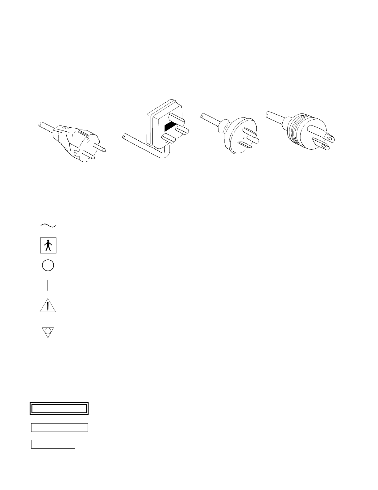
Check the standard power plug configurations that are used in your country. If the appropriate power cord is not
included in your product, notify your local MAHE distributor.
Continental Europe U.K. Australia U.S.A. and
(Use a SEV approved and Canada
plug for Switzerland) New Zealand
(Hospital Grade)
SYMBOLS ON MARKING
Alternating current
Type BF applied part (Safety degree specified by IEC 601-1)
OFF (Power: disconnection from the mains)
ON (Power: connection to the mains)
Attention, consult accompanying documents
Equipotentiality
CONVENTIONS
The following conventions have been established for the text of this manual to aid in the identification of potential
hazards of operation:
! WARNING
CAUTION
NOTE
: Could result in death or serious injury.
: May result in minor or moderate injury or property-damage.
: May result in property-damage. Also, advises owner/operator about important
information on the use of this equipment.
Page 9

3. SPECIFICATIONS
Item Specification
Number of Pixels PAL 795 (H) x 596 (V), approximately 470,000 pixels
Pick-up Element Interline transfer CCD 1/3" image sensor
Scanning System 2:1 interlace
Minimum Illumination Less than 1.5 Lux @ F 1.2
Resolution 470 TV lines (horizontal)
Signal/Noise Ratio Greater than 46dB @ AGC off
Gain Control Automatic Gain Control and manual Gain boost
White Balance Fast auto white balance (less than 1.0 second)
Electronic Shutter Automatic windowed shutter
Video Outputs Composite video signal 1.0V ptp @ 75 Ohm
Power Supply 100-240VAC @ 50/60Hz automatic
Power Consumption Approximately 20 Watt
Optical Interface CS or C-mount (C-mount with extension ring)
Regulatory Approvals IEC 60601-1, IEC 60601-1-2
Equipment Class Class 1, camera head BF-type
Mode of Operation Continuous operation
Water Resistant Camera head connected to cable is fully soak able (Watertight
Operating Environment
Temperature
Relative Humidity
Air Pressure
Storage Environment
Temperature
Relative Humidity
Air Pressure
Camera Head
Dimensions
Camera Head Weight 40 g
Camera Control Unit
Dimensions
Camera Control Unit
Weight
9
NTSC 811 (V) x 508 (V), approximately 410,000 pixels
Manual RED and BLUE fine tuning
1/50 (PAL) or 1/60 (NTSC) to 1/250,000 seconds
Y/C (S-VHS) Y=1.0V, C(Burst)=0.3V ptp @ 75 Ohm
RGBS R,G,B=0.7V, Sync=2.1V ptp @ 75 Ohm
Equipment, Class IPX7), camera control unit - Not Protected
Equipment, Class IPX0
+10° to +40° C (50° to 104° F)
30 to 85%
700 to 1060 hPa
-20° to +60° C (-4° to 140° F)
0 to 95%
700 to 1060 hPa
33 x 33 x 46 mm
295 (W) x 75 (H) x 253 (D) mm
1.8 kg
Page 10
10
4. OPERATING ELEMENTS, SYMBOLS AND FUNCTIONS
4.1 VIDEO CAMERA
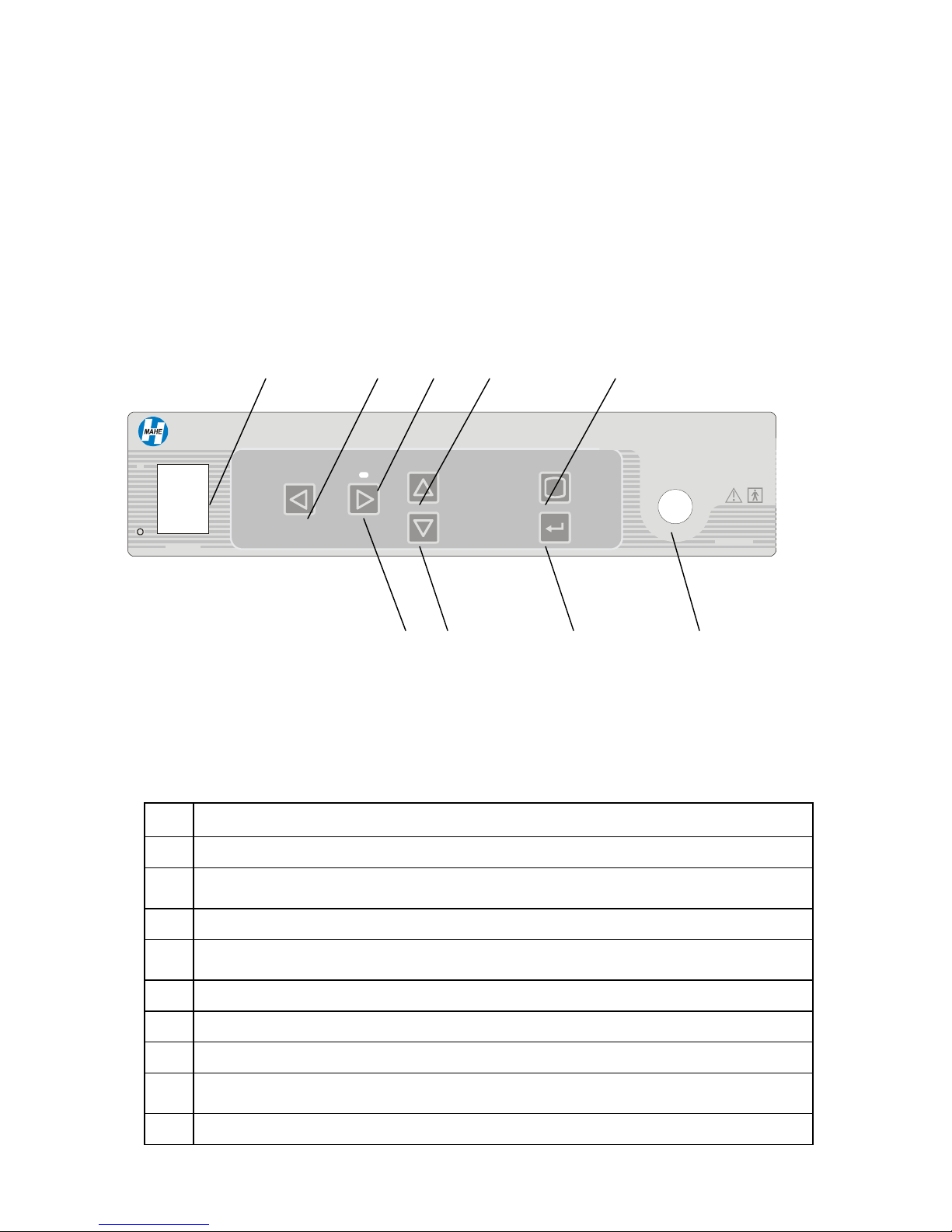
The video camera consists of the camera control unit, camera head and opto-mechanical adapter.
4.1.1 Camera control unit - front panel
1 2 3 4 5
MSV-2010
I
WHITE
BALANCE
GAIN BRIGHTNESS
MENU
Digital Video Camera
9 8 7 6
POWER
Fig.1 Camera control unit front panel
No Description
1 Main power switch with neon lamp indicator
2 White balance button for automatic white balance control / Left scroll button in Menu
mode
3 Green LED indicating activated Gain function
4 Brightness up button for manual brightness adjustment / Up scroll button in Menu
mode
5 Menu button for entering in Menu mode
CAMERA
6 Camera head cable connector
7 Enter button for entering in sub-Menu
8 Brightness down button for manual brightness adjustment / Down scroll button in
Menu mode
9 Gain on/off button for boosting low light images / Right scroll button in Menu mode
Page 11
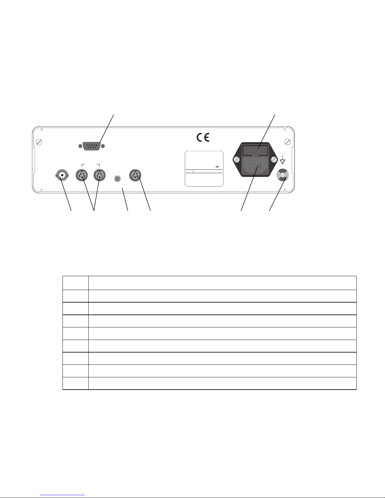
4.1.2 Camera control unit - rear panel
1 2
RGB
VIDEO
Y/C
REMOTE
KEYBOARD
11
INPUT 100-240V~ 50/60Hz
RATING 25VA MAX
SERIAL No.
FUSE 2xT2AL 250V
WARNING
For continued protection
against fire hazard
replace only with same
type and rating of fuse.
8 7 6 5 4 3
Figure 2. Camera control unit rear panel
No Description
1 RGBS video output connector (9-pin D-type)
2 Power fuses (type T2A, 250V)
3 Equipotentiality pin (grounding)
4 AC mains power inlet
5 Keyboard connector (6-pin mini DIN type connector)
6 Remote control connector (3.5mm jack) to operate peripheral devices
7 Y/C video outputs (2 x 4-pin mini DIN type connector)
8 Composite video output (BNC connectors)
Page 12
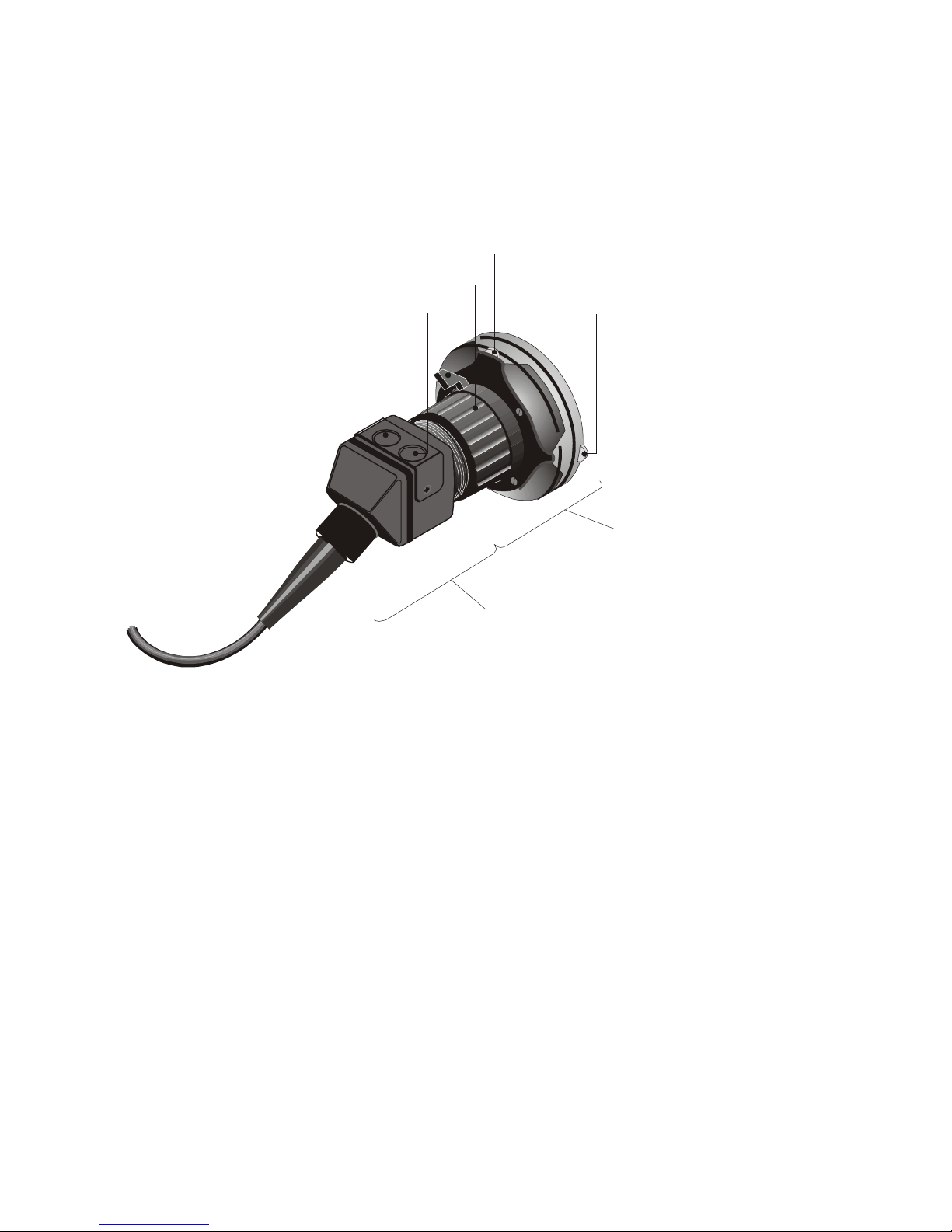
4.1.3 Camera Head and Opto-mechanical Adapter
4
3
2
1
12
5
6
Opto-mechanical
adapter
Camera head
Figure 3. Camera head and opto-mechanical adapter
1 2 3 4
Page 13

No Description
1 “1” button (refer to Section 6.14)
2 “2” button (refer to Section 6.14)
3 Free-spin lock
4 Focus ring
5 Right/left adjustment knob (optional)
6 Up/Down adjustment knob (optional)
Page 14
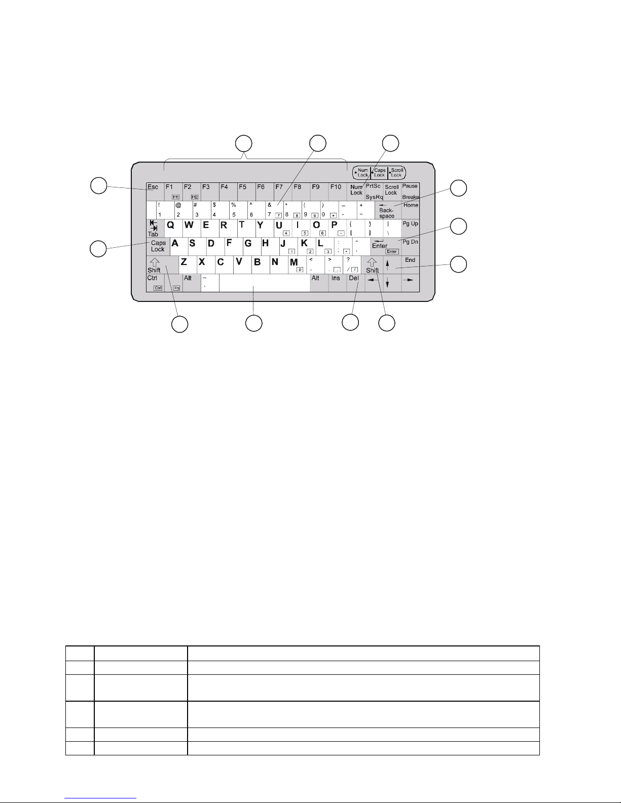
4.2 KEYBOARD (Optional)
14
2
8
3
4
5
6
7
11
10
1
7
9
Figure 4. Keyboard
No Name Function
1 Function Keys Refer to Function key indexes
2 Alpha-Numeric
keys
3 Num Lock key Locks function of number keys to print numbers only. Status indicator will
4 Backspace key Moves cursor leftward and deletes the character
5 Enter key Moves cursor to the next field
Include keys for letters, numbers and special characters (brackets, commas,
etc)
light when selected
Page 15

6 Cursor Movement
keys
7 Shift keys When caps Lock is Off, holding the Shift key and pressing alpha-numeric
8 Delete key Deletes the characters
9 Space Bar Creates space and deletes a previously typed character
10 Caps Lock key Caps Lock indicator will light to show Caps Lock selected. When Caps
11 Esc key Return to the normal mode
Up, Down, Left and Right arrows move the cursor to each direction when
Num. Lock is Off
key will cause a capital letter or special character pictured on the key to
appear on the screen
Lock is On, all alpha-bet keys will appear on the monitor screen as capitals
Note: To get F11 (F12) keys press Fn and F1(F2) simultaneously
Page 16
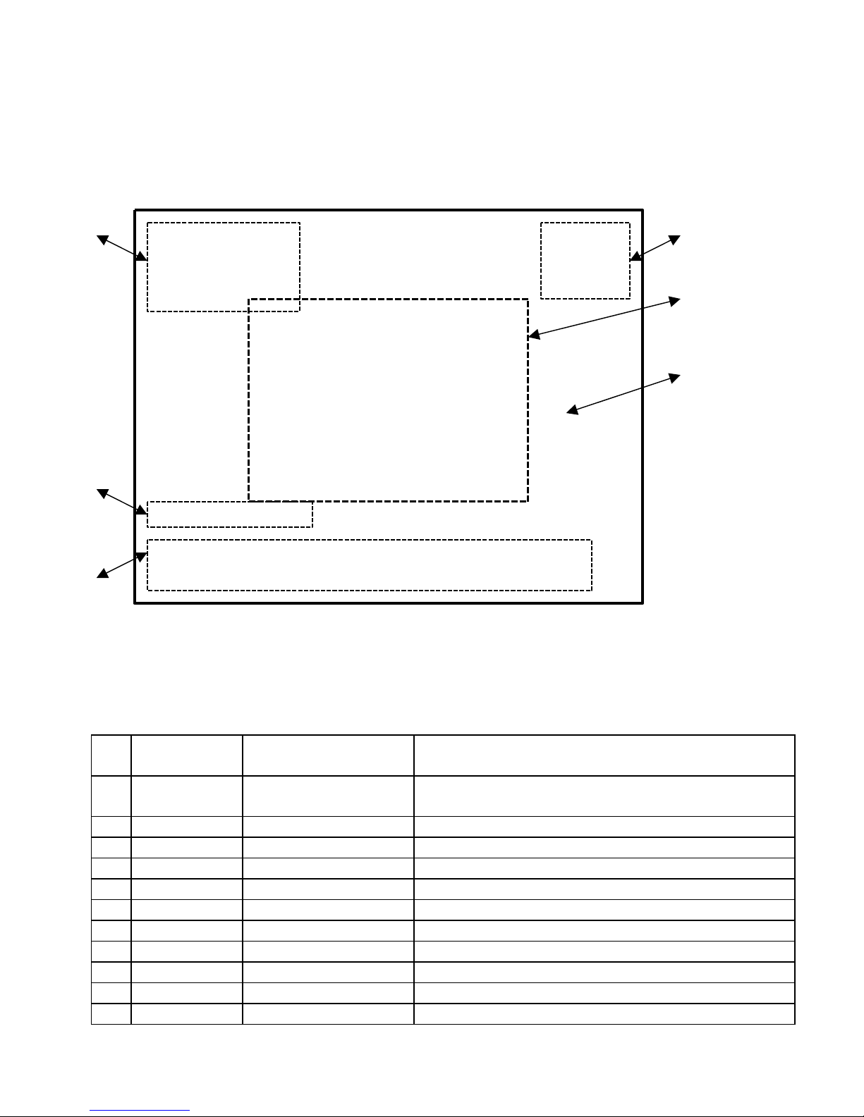
16
4.3 MONITOR SCREEN DISPLAY
6 NAME: 17/03/04 1
ID: 12:51:28
AGE: [ 00:46:28 ]
SEX:
MAIN MENU
-----------------------------------
PICTURE SETTING
SCREEN SETTING
BUTTON SETTING
CLOCK SETTING
DEFAULT SETTING
2
3
5
W/B OK
Central City Hospital
4
Figure 5. Monitor screen display
No Display
Window
1 Date & Time Date Numeric field (Month/Day/Year or Day/Month/Year)
Time Military format (Hours: Minutes: Seconds)
Stop watch Numeric display [Hours: Minutes: Seconds]
2 Menu Menu Area for keyboard and camera head menus
3 Main Screen Main Screen Endoscopic image
4 User User Window Alpha-numeric two lines field up to full line long
5 Message Message Window Alpha-numeric one line field 16 characters long
6 Patient Data Name Alpha-numeric field 24 characters long
ID Alpha-numeric field 16 characters long
Age Alpha-numeric field 3 characters long
Sex Alpha-numeric field 1 character long
Name Function
or Year/Month/Day
Page 17

17
5. INSTALLATION
5.1 SETTING UP THE MSV-2010
1. Place the video camera on a stable surface (cart, counter, stand, etc.).
NOTE - Avoid places where the video camera may be splashed with liquid.
- Absolutely DO NOT use in any environment with explosive or flammable gases.
- DO NOT block the venting grids of the video camera
2. Make sure the power switch is in OFF position.
3. Plug the power cord into the power source using the three (3) prong plug supplied with the unit.
CAUTION - To prevent electric shock, connect power cords of peripheral equipment through
medical isolation transformers.
NOTE - When using medical isolation transformer, be sure to check that the transformer ratings.
Make sure that the power cord is connected to the mains with a three prong plug
(In USA use UL2601-1 rated isolation transformers and/or power strips only).
5.2 CONNECTING THE CAMERA HEAD
CAUTION - When removing the camera head from the camera control unit, grasp the connector
.
area to release the lock mechanism. Pulling the cable could result in damages to the device.
NOTE - Do not connect or disconnect the camera head during operation. It may cause
unrecoverable damage to the camera head.
To connect the camera head to the camera control unit align the red dot on the camera cable connector with the red
dot on the CAMERA jack, located on the left side of the camera control unit front panel. Gently push the connector
into the jack.
5.3 CONNECTING PERIPHERAL EQUIPMENT
1. The MSV-2010 can be connected to a video monitor via three types of video signals: composite video, Y/C
(S-VHS) or RGB.
It is possible to connect up to four appliances including the monitor simultaneously to the different video
outlets of the MSV-2010: VCRs, Image Processing PCs (via frame grabbers) and/or video printers.
2. Depending on the requirements of appliances you will be using, attach the appropriate cables to the rear panel
of the camera control unit. For example, if the monitor requires input from a Y/C cable, attach one end of the
Y/C cable to the corresponding connector on the rear panel of the camera control unit and the other end to the
monitor.
NOTE - For highest quality pictures Y/C or RGB connections are recommended
CAUTION - When used in clinical or residential areas near radio or TV units, this equipment
may be subjected to radio interference. To avoid adverse electromagnetic effects,
DO NOT operate this equipment near RF energy equipment.
Page 18

18
CAUTION - Use the following connection cables provided with the MSV-2010 and use
keyboard with appropriate CE Marking.
- Use the part # H10-0015 for the RGB Video Cable. Use of other cables could cause poor
images or excessive heat resulting in injury or property-damage.
Name Description Length Qty Part No
RGB Video Cable 9pin D-type – 4 x BNC 2.0m 1 H10-0015
Y/C Video Cable 4pin Mini Din - 4pin Mini Din 1.5m 1 H10-0037
Remote Control Cable Mini Jack – Mini Plug 1.5m 1 H10-0038
Composite Video Cable BNC – BNC 1.5m 1 H10-0039
5.4 CONNECTING POWER
1. Connect the AC power cable to the inlet located on the rear panel of the camera control unit.
2. Plug the AC power cable into a wall outlet.
5.5 ASSEMBLING THE OPTO-MECHANICAL ADAPTER
1. Attach the opto-mechanical adapter to the camera head by screwing it into the camera head and tighten slightly.
Make sure first to insert the semicircular flange on the opto-mechanical adapter into the semicircular socket on
the camera head.
NOTE - While assembling the opto-mechanical adapter and connecting it to the camera head,
please make sure that the free-spin lock on the opto-mechanical adapter (refer to Figure 3)
is in its locked position.
Page 19

19
6. OPERATION
6.1 POWERING UP THE MSV-2010
To operate the MSV-2010:
1.Attach the endoscope to the opto-mechanical adapter connected to the camera head (refer to Section 5.5).
2. Attach the light source to the endoscope.
3. Turn on the video camera, monitor and light source. Wait until SETTING list is appeared on the monitor
screen. Do not press any front panel buttons or camera head buttons and any keyboard key until date, time and
patient data window are appeared on the monitor screen.
4. Use the focus ring of the opto-mechanical adapter to focus the image. The image positioning on the screen can be
adjusted by the free-spin/orientation mechanism (refer to Section 6.2) and the optional centering mechanism (refer
to Section 6.3), of the opto-mechanical adapter.
5. Perform the white balance procedure (refer to Section 6.5.1).
6. At any time the image can be adjusted using the touch-buttons on the front panel of the camera control unit
by:
a) Adjusting the brightness level (refer to Section 6.5.3).
b) Using gain control (refer to Section 6.5.2).
NOTE - When the image is being adjusted, text messages appear on the upper line of the message
window of the monitor screen display.
6.2 FREE-SPIN/ORIENTATION MECHANISM
1. While using a flexible endoscope, release the free-spin lock of the opto-mechanical adapter (refer to Figure 3)
and rotate the endoscope until the arrow in the view field points to twelve o’clock. Then return the free-spin
lock to its locked position.
2. When using rigid endoscopes, release the free-spin lock of the opto-mechanical adapter, rotate the endoscope
to the required position, then return the free-spin lock to its locked position.
6.3 CENTERING MECHANISM
1. When the opto-mechanical adapter has a centering mechanism (optional), it can be used to center the image
from a flexible endoscope on the screen.
2. The centering mechanism has two adjustment knobs (refer to Figure 3). When the view field of the flexible
endoscope is correctly oriented at twelve o’clock, the knobs are positioned on the top and the right side of the
mechanism. Turn these knobs to move the image up or down (right knob) and right or left (top knob) on the
monitor.
Page 20

20
6.4 FUNCTION CONTROLS
The MSV-2010 functions may be controlled from either:
•1 front panel of the camera control unit;
•2 keyboard;
•3 camera head buttons.
6.4.1 Function control from the front panel of the Camera Control Unit (CCU)
The CCU front panel buttons have different functions in normal operation mode and in menu mode.
Function control WHITE BALANCE, GAIN and BRIGHTNESS are performed by pressing corresponded buttons
on the front panel (refer to Fig.1 and Section 6.5).
Control of all other functions are performed via main menu by using MENU, ENTER , ?, ?, ? and ? buttons
(refer
to Fig.1 and Section 6.6).
1. When the MENU button is being held for approximately two seconds the menu mode shall be activated and the
MAIN MENU shall appear on the monitor screen. The selected item shall appear on a green background.
2. Scrolling up and down between the main menu items shall be performed by the ? and ? buttons.
Holding the ? or ? button for longer than approximately 0.5 second (reference value) shall scroll sub-menu items
automatically (0.1 second per step).
3. To open a sub-menu, the green background shall be brought to the selected item and the ENTER button shall
be pressed.
4. Scrolling up and down between the sub-menu items shall be performed by pressing the ? and ? buttons. The
selected item shall appear on a green background. Holding the ? or ? button for longer than approximately 0.5
second (reference value) shall scroll sub-menu items automatically (0.1 second per step).
Changing value of a sub-menu item shall be performed by pressing the ? or ? buttons. Holding the ? or ? button
for longer than approximately 0.5 second (reference value) shall change the item value automatically (0.1
second per step).
6.4.2 Function control from keyboard
1. Function control from the keyboard is performed by using F function keys and combination Ctrl +F keys.
2. Pressing some of the F and Ctrl+F keys will call for appropriate function menus. In addition, two sub-
menus can be called from the Picture Set menu.
3. Selected menu item is highlighted.
4. To scroll the selected menu item up or down use arrow keys ↑ ↓ of the keyboard.
5. To activate a new menu item, select it by ↑ ↓ keys and press Enter key. The selected item shall appear on a
green background.
6. Every time the arrow key is pressed, it scrolls the selection one item up or down. Hold the arrow key for
approximately one second to scroll automatically until the key is being held.
7. To escape at any time, press the Esc key.
6.4.3 Function control from camera head buttons
1. Function control from the camera head buttons is performed according to the button setting (refer to Section 6.18).
Page 21

21
6.5 NORMAL OPERATION MODE
Function control in the normal operation mode (WHITE BALANCE, GAIN and BRIGHTNESS) is performed
by pressing corresponded buttons on the front panel (refer to Figure 1).
6.5.1. White Balance
When operating the system for the first time, or if illumination conditions had changed, or if colors seem to differ
from “true” colors, perform a white balance procedure as follows:
1. With the endoscope attached to a working light source and video camera, focus on a white object (such as a
white cloth or sheet of paper). Make sure the picture is not saturated by excessive illumination.
2. Press the WHITE BALANCE button on the front panel of the camera control unit (refer to Fig.1) for
approximately two seconds, until short beep shall be heard. After at least one second “W/B OK” message shall
be appears on the monitor screen and second short beep shall be heard. f white balance routine is not successful
the message “W/B FAILED” shall be displayed and a long beep shall be heard
3. When operating from keyboard, press Ctrl + F2 buttons and short beep shall be heard. After at least one second
“W/B OK” message shall be appears on the monitor screen and second short beep shall be heard. .
If white balance routine is not successful the message “W/B FAILED” shall be displayed and a long beep shall
be heard.
4. The white balance setting is stored in the non-volatile memory and there is no need to adjust it again unless the
illumination conditions change.
6.5.2 Gain Control
In case of a dark or badly illuminated object, the user can activate the gain control to further increase the
brightness of the image. When starting the system, the gain control is set to off.
1. To activate the gain control press the GAIN button on the front panel of the CCU (refer to Fig.1). Message
GAIN ON will appear on the monitor screen and the GAIN LED will illuminate.
2. To deactivate the gain control, press the GAIN button again. Message GAIN OFF will appear on the monitor
screen and the GAIN LED will turn off.
NOTE - Using activated gain function adds noise to the obtained image
6.5.3 Brightness Adjustment
1. The brightness adjustment enables the user to obtain a brighter or darker image by increasing or decreasing
the automatic shutter reference level.
2. Adjust the brightness by pressing one of the BRIGHTNESS buttons on the front panel of the control unit
(refer to Figure 1). Press the upper BRIGHTNESS button to increase the brightness. Press the lower
BRIGHTNESS button to decrease the brightness. Every time either the upper or the lower button is pressed,
the brightness changes incrementally. The message BRIGHTNESS – 5 to BRIGHTNESS +
on the
monitor screen indicating the brightness level. Holding the button for approximately one second will
change the color intensity level automatically until the button is being held.
5 will be appear
3. Each pressing the upper or down BRIGHTNESS button after the maximum brightness has been reached, short
beep shall be heard.
Page 22

22
6.6. MENU OPERATION MODE
Control of functions in the menu operation mode is performed via main menu by using MENU, ENTER , ?, ?, ?
and ? buttons
← → of the keyboard (refer to Fig.4).
on the front panel of CCU (refer to Fig.1 and Section 6.6) or using ENTER, Esc and arrow keys ↑ ↓
6.6.1. Main Menu
1. Press and hold pressed the MENU button on the front panel of CCU for approximately two seconds or press the
Ctrl and F1 keys of the keyboard simultaneously. The MAIN MENU shall appear on the monitor screen. The
selected item shall appear on a green background.
MAIN MENU
-------------------------------PICTURE SETTING
SCREEN SETTING
BUTTON SETTING
CLOCK SETTING
DEFAULT SETTING
2. To activate a new menu item, select it by ? ? buttons or ↑ ↓ keys. The selected item shall appear on a
green background.
3. To open a sub-menu press Enter button on the front panel or Enter key of the keyboard.
6.6.2 Picture Setting Sub-Menu
This sub-menu shall allow checking or changing the following picture parameters.
PICTURE SETTING
------------------------------------------------------GAIN OFF
BRIGHTNESS -1
COLOR RED +5
COLOR BLUE -2
ENHANCE MEDIUM
SHUTTER
FULL
WINDOW
SHUTTER SPEED AUTO
FREEZE MODE FIELD
6.6.2.1 Gain
GAIN control is activated by ← → key of the keyboard or ? ? buttons on the front panel.
To leave sub-menu press Esc key or MENU button.
NOTE - Using activated gain function adds noise to the obtained image
23
Page 23

NOTE - When starting the system, the gain control is set to off.
6.6.2.2. Brightness
BRIGHTNESS is increased by → key of the keyboard or ? button on the front panel. BRIGHTNESS is
decreased by
← key of the keyboard or ? button on the front panel.
The message BRIGHTNESS – 5 to BRIGHTNESS +
brightness level.
Each pressing by the
short beep shall be heard.
To leave sub-menu press Esc key or MENU button.
← → key or ? ? buttons after the maximum or minimum brightness has been reached,
5 will be appeared on the monitor screen indicating the
6.6.2.3 Color Red and Color Blue
. After adjusting the white balance, or at any time during operation, the user may wish to fine tune the colors
appearing on the monitor.
The intensity of the color is increased by
intensity of the color is decreased by
The message RED (BLUE) – 20 to RED (BLUE) +
color level.
Each pressing by the
short beep shall be heard.
To leave sub-menu press Esc key or MENU button.
← → key or ? ? buttons after the maximum or minimum color level has been reached,
→ key of the keyboard or ? button on the front panel. The
← key of the keyboard or ? button on the front panel.
20 will be appeared on the monitor screen indicating the
6.6.2.4 Enhance
The ENHANCE function provides the user to obtain sharper and clearer image. The ENHANCE feature
provides three levels of image enhancement: LOW, MIDDLE and HIGH.
NOTE - When the CCU is turned Off, the enhance function will default to the same state which
it was in when the CCU was last turned Off.
Each pressing by the
MIDDLE → HIGH → OFF → …” and reflects setting to image and display current setting.
To leave sub-menu press Esc key or MENU button.
← → key or ? ? buttons changes enhancement level in order: “OFF → LOW →
6.6.2.5 Shutter Window
The SHUTTER WINDOW function is allowed to select the size of the central part of observation in order to
achieve the best image of the observing object.
The shutter window feature provides three sizes of the measuring area: Small, Medium and Full.
Page 24

24
Each pressing by the
← → key or ? ? buttons changes the window size in order: “SMALL → MEDIUM →
FULL → SMALL → …” and appropriate window size is shown on the monitor screen.
To leave sub-menu press Esc key or MENU button.
6.6.2.6 Shutter Speed
The SHUTTER SPEED function is allowed to user select the automatic or manual shutter control.
The shutter speed feature provides automatic speed control and eleven manual settings.
Each pressing by the
1/250 → 1/500 → 1/1000 → 1/2500 → 1/5000 → 1/10000 → 1/25000 → 1/50000 → 1/100000 → AUTO →
…” and reflects setting to image and display current setting.
Each pressing by the
1/25000 → 1/10000 → 1/5000 → 1/2500 → 1/1000 → 1/500 → 1/250 → 1/100 → MAX → AUTO →
1/100000…” and reflects setting to image and display current setting.
To leave sub-menu press Esc key or MENU button.
6.6.2.7 Freeze Mode
The FREEZE MODE function is allowed to user select the best quality of the frozen picture.
→ key or ? buttons changes the shutter speed in order: “AUTO → Max → 1/100 →
← key or ? buttons changes the shutter speed in order: “1/100000 → 1/50000 →
If the endoscopic image is relatively stable, the frozen image in the “FRAME” mode will be clear and sharper.
If the endoscopic image is unstable, the frozen image will be clear in the “FIELD” mode.
Each pressing by the
← → key or ? ? buttons will change freeze mode.
To leave sub-menu press Esc key or MENU button.
6.6.3 Screen Setting Sub-Menu
This sub-menu shall allow checking or changing the following picture parameters.
SCREEN SETTING
--------------------------------------------------------------
PATIENT DATA ON
USER WINDOW ON
CLOCK DISPLAY ON
COPY MODE A FREEZE KEEP
COPY MODE B COPY SCREEN
PIP LOCATION RIGHT-UP
COLOR BARS ON – OFF
6.6.3.1 Patient Data
PATIENT DATA area is appeared on the screen by pressing ← → key of the keyboard or ? ? buttons on
the front panel. Pressing the
← → key or ? ? buttons toggles PATIENT DATA area ON and OFF.
To leave sub-menu press Esc key or MENU button.
Page 25

25
6.6.3.2 User Window
USER WINDOW area is appeared on the screen by pressing ← → key of the keyboard or ? ? buttons on
the front panel. Pressing the
To leave sub-menu press Esc key or MENU button.
← → key or ? ? buttons toggles USER WINDOW area ON and OFF.
6.6.3.3 Clock Display
CLOCK DISPLAY area is appeared on the screen by pressing ← → key of the keyboard or ? ? buttons
on the front panel. Pressing the
To leave sub-menu press Esc key or MENU button.
← → key or ? ? buttons toggles CLOCK DISPLAY area ON and OFF.
6.6.3.4 Copy Mode A
COPY MODE A function is intended to select the freeze mode after providing the copy pulse.
In FREEZE KEEP mode frozen image is kept on the screen after the end of copy pulse.
In FREEZE REALIZE mode the image is unfrozen after the end of copy pulse.
Pressing the
To leave sub-menu press Esc key or MENU button.
← → key or ? ? buttons toggles FREEZE KEEP and FREEZE REALIZE mode.
6.6.3.5 Copy Mode B
COPY MODE B function is intended to select the copy screen mode. In COPY SCREEN mode the
current picture is captured by video printer. In ADD DATA mode the current picture is captured together
with the patient data, clock data and user data.
Pressing the
To leave sub-menu press Esc key or MENU button.
← → key or ? ? buttons toggles COPY SCREEN and ADD DATA mode.
6.6.3.6 PIP Location
PIP LOCATION function is intended to select location of the sub-screen. the copy screen mode. Each
pressing by the
→ RIGHT-DN → LEFT-DN → LEFT-MID → LEFT-UP → RIGHT-UP → …” and display current sub-
screen location.
Each pressing by the
LEFT-MID → LEFT-DN → RIGHT-DN → RIGHT-MID → RIGHT-UP → …” and display current subscreen location.
To leave sub-menu press Esc key or MENU button.
→ key or ? buttons changes sub-screen location in order: “RIGHT-UP → RIGHT-MID
← key or ? buttons changes sub-screen location in order: “RIGHT-UP → LEFT-UP →
6.6.3.7 Color Bars
COLOR BARS are appeared on the screen by pressing ← → key of the keyboard or ? ? buttons on the
front panel. Pressing the
← → key or ? ? buttons toggles COLOR BARS ON and OFF.
Page 26

26
To leave sub-menu press Esc key or MENU button.
6.6.4 Button Setting Sub-Menu
This sub-menu allows programming each camera head button individually.
BUTTON SETTING
----------------------------------------------
BUTTON 1 COPY
BUTTON 2 ENHANCE
1. Each pressing by the → key or ? buttons changes the function of each CH button in order: “GAIN →
ENHANCE → SHUTTER SPEED UP → SHUTTER SPEED DN → FREEZE → COPY → STOP WATCH
→ WHITE BALANCE → GAIN →…”.
2. Each pressing by the
BALANCE → STOP WATCH → COPY → FREEZE → SHUTTER SPEED DN → SHUTTER SPEED UP →
ENHANCE → GAIN → …”.
To leave sub-menu press Esc key or MENU button.
NOTE -When the button is programmed for ENHANCE: a message with enhance status(ENHANCE OFF
ENHANCE LOW, ENHANCE MEDIUM or ENHANCE HIGH) will appear in the message window.
NOTE -When the button is programmed for SHUTTER SPEED UP or DN: a message with shutter speed
NOTE - When the button is programmed for COPY value: a short beep will be heard when the COPY
button is pressed
6.6.5 Clock Setting Sub-Menu
This sub-menu allows date and time setting.
← key or ? buttons changes the function of each CH button in order: “GAIN → WHITE
value will appear in the message window, message with manual shutter speed value will remain
constantly, message AUTO will disappear after approximately five seconds(reference value)
CLOCK SETTING
--------------------------------------------------------
DATE STYLE DD/MM/YY
YEAR 04
MONTH 04
DAY 1
HOUR 15
MINUTE 02
STOP WATCH START
6.6.5.1 Date Style
The format for the Date Style is DD/MM/YY, MM/DD/YY or YY/MM/DD (European, American
or Japanese style)
DD = Day, MM = Month, YY = Year
27
Page 27

1. Each pressing by the → key or ? buttons changes DATA STYLE in order: “DD/MM/YY → MM/DD/YY →
YY/MM/DD → DD/MM/YY → …” and display current setting in the clock display area.
2. Each pressing by the
← key or ? buttons changes DATA STYLE in order: “DD/MM/YY → YY/MM/DD
→ MM/DD/YY → DD/MM/YY → …” and display current setting in the clock display area.
6.6.5.2 Year, Month, Day, Hour, Minute
After DATE STYLE set YEAR, MONTH, DAY, HOUR and MINUTE.
The format for the Time is HH:MM:SS
HH = Hours military notation, MM = Minutes, SS = Seconds
AM hours are expressed as number. Example: 7AM = 07
PM hours are expressed as the hours + 12. Example: 7PM = 7 + 12 = 19.
1. Each pressing by the
Month in order: “01 → 02 → … → 12”, Day in order: “01 → 02 → … → 31”,
Hour in order: “00 → 01 → … → 23”, Minute in order: “00 → 00 → … → 59” and display current
setting in the clock display area.
2. Each pressing by the
Month in order: “12 → 11 → … → 01”, Day in order: “31 → 30 → … → 01”,
Hour in order: “23 → 22 → … → 00”, Minute in order: “59 → 58 → … → 00” and display current
setting in the clock display area.
→ key or ? buttons changes YEAR in order: “00 → 01 → … → 99”
← key or ? buttons changes YEAR in order: “99 → 98 → … → 00”,
3. To set the date style and clock the Enter button or Enter key shall be pressed (seconds shall reset to 00).
6.6.5.3 Stop Watch
Stop Watch is appeared on the screen below Time field and stars counting by pressing ← → key of the
keyboard or ? ? buttons on the front panel.
The stop watch format is: [HH: MM: SS]
HH = Hours, MM = Minutes, SS = Seconds
Pressing the ← → key or ? ? buttons changes stop watch operation in order: “OFF → START → STOP
→ OFF →…”.
To leave sub-menu press Esc key or MENU button.
6.6.6 Default Setting
1. To set the factory default settings, the DEFAULT SETTING item on the main menu shall be selected and
the ENTER button or ENTER key shall be pressed.
Pressing the ? ? button or ↑ ↓ keys shall restore the current or factory settings alternatively.
DEFAULT SETTING
---------------------------------------
CURRENT SETTINGS
FACTORY SETTINGS
28
2. The FACTORY SETTINGS parameters shall be as follows.
Page 28
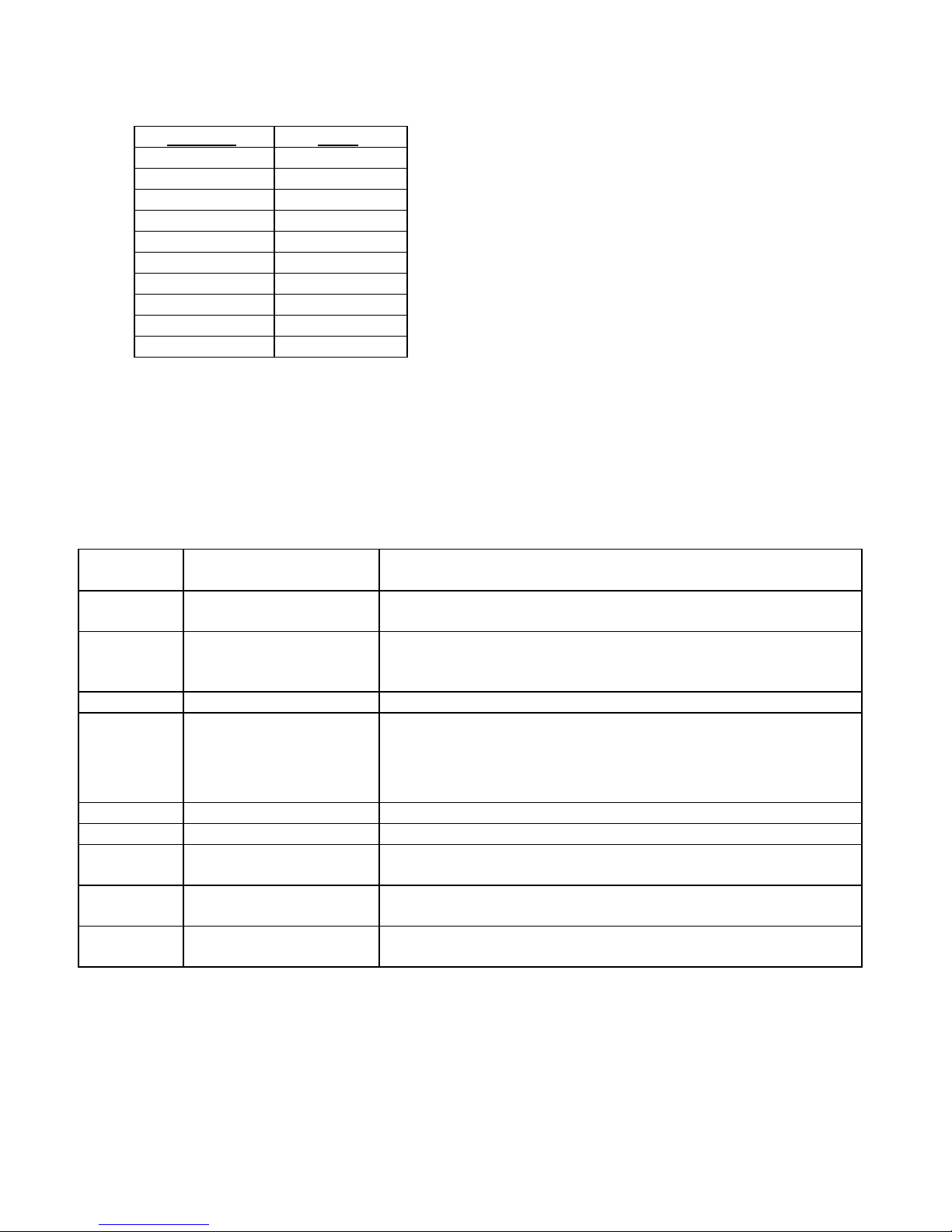
Parameter Value
Gain OFF
Brightness 0
Color Red 0
Color Blue 0
Enhance MEDIUM
Shutter Window FULL
Shutter Speed AUTO
Freeze Mode FIELD
Copy Mode A FREEZE REL
Copy Mode B ADD DATA
6.7 KEYBOARD OPERATION
6.7.1 Short Keys (F)
The following functions shall be assigned to the F keys.
Key Function
F1 SCREEN DATA
ON/OFF
F2 ENHANCE Cycles image enhancement level through OFF, LOW, MEDIUM
F3 FREEZE Toggles freeze function on and off
F4 COPY
F5 STOP WATCH Cycles stop watch through OFF, START and STOP
F6
F7 SHUTTER SPEED UP Increases shutter speed; message window shall show the shutter
F8 SHUTTER SPEED DN Decreases shutter speed; message window shall show the shutter
F10 FUNCTION LIST Turns on list of functions for F keys; the list shall disappear after
Notes
Toggles patient data, user window data and clock display On and
Off
and HIGH shown in the message window after word
“ENHANCE”
The copy function is intended to activate image capturing or taping
(such as video printer, VCR, etc.) peripheral equipment (please
read carefully the instructions for the peripheral equipment).
Activates copy function; a short beep shall be heard
speed
speed
approximately 10 seconds or if any key is pressed
Page 29
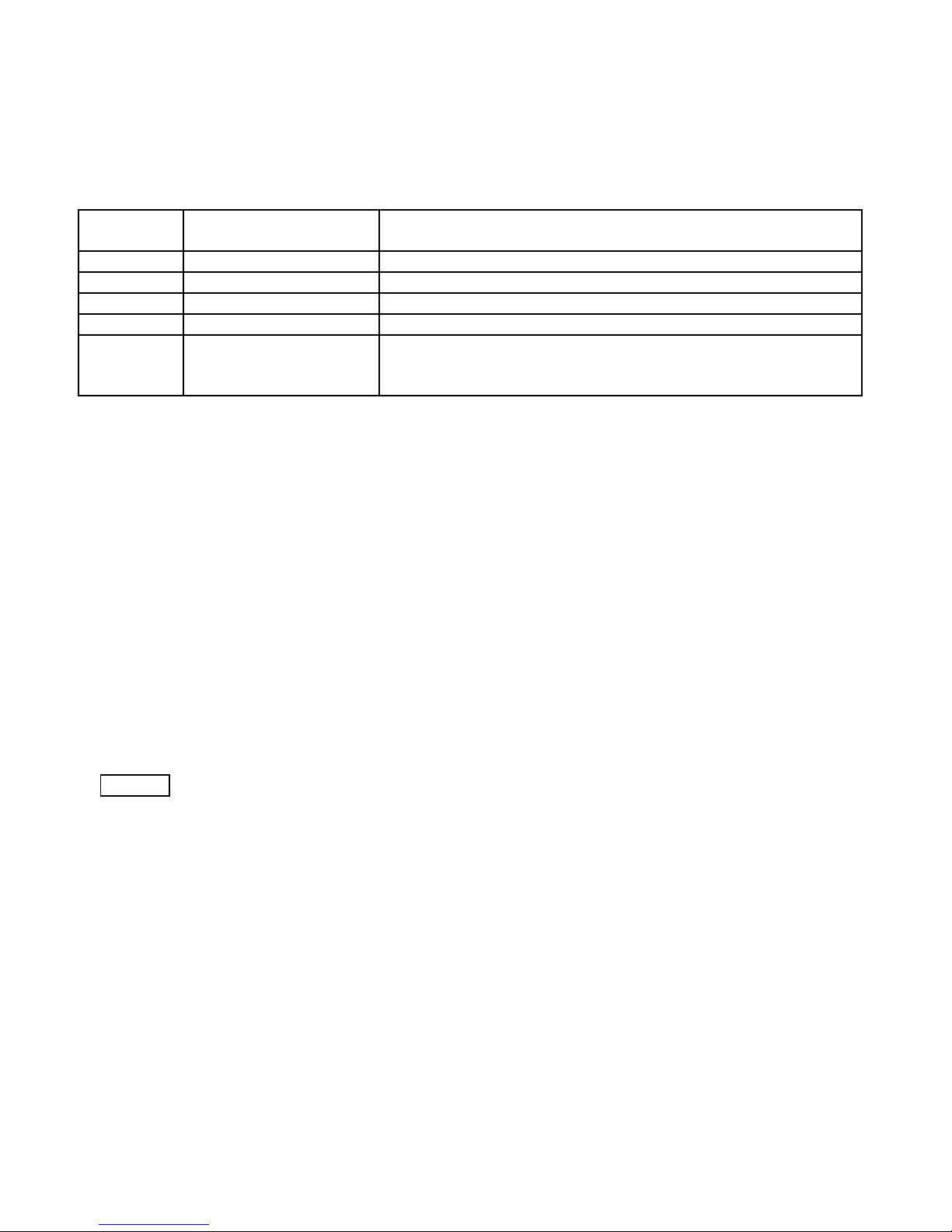
6.7.2 Short Keys combination (Ctrl + F)
The following functions shall be assigned to the Ctrl +F keys combination.
Keys
CTRL+F1 MAIN MENU Calls for the MAIN MENU
CTRL+F2 WHITE BALANCE Initiates white balance routine as per 3.5.1
CTRL+F3 DATA ENTRY See 3.8.4, 3.8.5
CTRL+F4 CHARACTERS RESET Resets patient data
CTRL+F10 FUNCTION LIST Turns on list of functions for Ctrl+F key combinations; the list
6.7.3 Entering Patient Data
1. New data entry shall be enabled by pressing the Ctrl and F3 keys simultaneously (a blinking cursor shall paint in
green the first character of the “NAME” title or the patient name). The patient data shall overwrite the titles. The
cursor moves by ÎÍ keys after the title is removed. The letters can be modified by character keys, then the
cursor moves to the next letter automatically. Modification moves between lines (to the first line character) by Ï
Ð keys.
The following patient data may be keyed in from the keyboard:
a) Patient name - up to 24 characters.
b) Patient ID - up to 16 characters.
c) Patient age - up to 3 characters.
d) Patient sex - 1 character.
2. To leave the entering data mode the Esc key shall be pressed, after that the cursor shall disappear.
3. To reset the patient data the Ctrl and F4 keys shall be pressed simultaneously, the data characters shall
disappear and the titles shall appear
NOTE - The patient data shall be stored and shall not be erased after turning the power off.
4. The protocol of character input shall be as follows:
a) The cursor shall appear first at pressing Ctrl and F3 keys simultaneously.
b) The cursor shall move forward to the next item when Ð key is pressed, and backward when Ï key is
pressed.
c) The cursor shall move within the item by ÎÍ keys.
d) Space key shall write blank letter in the cursor location, then the cursor shall advance.
e) Backspace key shall return the cursor to a front location, shall write blank letter and the cursor shall stay
there.
f) Delete key shall write blank letter in a location of the cursor and the cursor shall stay there.
g) Holding the Shift key and typing an alpha key shall display the capital letter or upper case special
character.
h) Pressing the Caps Lock key shall cause all alpha keys typed to be displayed as capitals.
If any entry is typed to an item and the number of characters exceeds the number of characters of the item, the
cursor shall stop at the last character of the item and display the last character typed.
29
Function Notes
shall disappear after approximately 10 seconds or if any key is
pressed
30
Page 30

6.7.4 Entering User Window Data
1. New data entry shall be enabled by pressing Ctrl and F3 keys simultaneously (see 3.8.4). The cursor shall be
brought to the user window by the Ð key. The Ð key shall also move the cursor to the second line, the Ï key
shall move the cursor up to the first line.
2. The protocol of character input shall be similar to described in 3.7.1.
NOTE - Resetting the patient data shall not reset the user window data.
3. The user window data shall be stored and shall not be erased after turning the power off.
31
Page 31
6.8 MENU SUMMARY
MAIN MENU
PICTURE SETTING
SCREEN SETTING
BUTTON SETTING
CLOCK SETTING
DEFAULT SETTING
PICTURE SETTING
Gain
Brightness
Color RED
Color BLUE
Enhance
Shutter Window
Shutter Speed
Freeze Mode
SCREEN SETTING
Patient Data
User Window
Clock Display
Copy Mode A
Copy Mode B
PIP Location
Color Bars
BUTTON SETTING
Button 1
Button 2
CLOCK SETTING
Date Style DD/MM/YY – MM/DD/YY – YY/MM/DD
Year 00 … 99
Month 1 … 12
Day 1 … 31
Hour 00 … 23
Minute 00 … 59
Stop Watch OFF – START - STOP
DEFAULT SETTING
Current Setting
Factory Setting
OFF – ON
- 5 … 0 …+ 5
- 20 … 0 … +20
- 20 … 0 … +20
OFF – LOW – MEDIUM - HIGH
SMALL – MEDIUM - FULL
AUTO – MAX – 1/100 – 1/250 – 1/500 – 1/1000 – 1/2500 – 1/5000 –
1/10000 – 1/25000 – 1/50000 – 1/100000
FIELD - FRAME
ON – OFF
ON – OFF
ON – OFF
FREEZE KEEP – FREEZE REL
COPY SCREEN – ADD DATA
LEFT-DN – LEFT-MID – LEFT-UP
ON – OFF
GAIN – ENHANCE – SHUTTER SPEED UP – SHUTTER
SPEED DN – FREEZE – COPY – STOP WATCH – WHITE BALANCE
GAIN – ENHANCE – SHUTTER SPEED UP – SHUTTER
SPEED DN – FREEZE – COPY – STOP WATCH – WHITE BALANCE
Page 32

32
7. CLEANING
NOTE - Always disconnect the power cable before cleaning the system
7.1 CAMERA CONTROL UNIT
1. The camera control unit can be cleaned with any cleaning agents, which is used for external cleaning of electric
equipment, according to the instructions given by the manufacturer of the cleaning solution.
Do not allow excessive moisture or liquids to reach direct contact with the camera control unit.
Do not use cleaning agents that are not permitted for use with plastics, such as: Ammonia, Acetone, salty acids
(HCl), etc.
The cleaning procedure should be performed while the camera head's cable is connected to the camera control unit.
Do not allow cleaning agents, or liquids to enter the camera control unit outlets.
7.2 CAMERA HEAD
1. The camera head, with or without the opto-mechanical adapter attached, should be cleaned with Alcohol (70%),
or ENZOL Enzymatic Determent, or soap water.
Use a soft cloth or cotton wool for cleaning. Do not use scrubbing material, such as a metal brush, that might
scratch the surface.
The cleaning procedure should be performed while the camera head’s cable is disconnected from the camera
control unit, protected by the connector’s protecting cap.
7.3 OPTO-MECHANICAL ADAPTER
The opto-mechanical adapter can be cleaned either while separated or attached to the camera head. Use Alcohol
(70%), or ENZOL Enzymatic Determent, or soap water to clean the opto-mechanical adapter.
If the opto-mechanical adapter is cleaned while separated from the camera head, make sure that you dried it well,
and that there are no loose threads left on the lenses before attaching it to the camera head.
7.4 GLASS WINDOWS ON CAMERA HEAD AND OPTO-MECHANICAL ADAPTER
On the front end of the camera head and on both ends of the opto-mechanical adapter there are protecting glass
windows.
Spray the glass windows with alcohol (70%) or with an anti-fog solution. Wait 2-3 seconds and dry with a soft
cloth.
33
Page 33

8. DISINFECTION AND STERILIZATION
8.1 DISINFECTING THE MSV-2010
NOTE - Always disconnect the power cable before cleaning the system
8.1.1 Camera Control Unit
1. Use any disinfecting agents which is commonly applied while disinfecting surfaces of electric medical
equipment. Such disinfecting agents usually arrive in the form of sprays or damp cloths.
2. Follow the instructions given by the manufacturer of the disinfecting solution.
3. The disinfecting procedure should be performed while the camera head's cable is connected to the camera
control unit. Do not allow disinfecting agents, or liquids to enter the camera control unit outlets.
8.1.2 Camera head and opto-mechanical adapter
1. Use water based solutions, which include the active substance gluteraldehyde (such as CIDEX), or other
alkaline substances.
2. Follow the instructions given by the manufacturer of the disinfecting solution.
3. The disinfecting procedure should be performed while the camera head's cable is disconnected from the
camera control unit protected by the connector's protecting cap.
4. After soaking in disinfecting solution, dry with soft cloth, in particular any exposed glass windows of the
opto-mechanical adapter and camera head.
5. It is recommended to disinfect the opto-mechanical adapter while attached to the camera head, in order to
prevent formation of fog between the camera head and opto-mechanical adapter. However, it is also possible
to disinfect them separately.
6. It is recommended to use anti-fog solution after completing the disinfecting procedure. Use the anti-fog only
on glass surface that was exposed during the disinfections. Follow the anti-fog solution manufacturer's
instructions.
8.2 STERILIZING THE CAMERA HEAD AND OPTO-MECHANICAL ADAPTER
1. The camera may not be autoclaved or sterilized with steam!
2. For sterilizing with sterilization solutions follow instruction in paragraph 8.1.2. (Disinfecting of camera head
and opto-mechanical adapters).
3. The camera can be sterilized with ETO or Formaldehyde gas. Follow the sterilization instructions given by the
manufacturer of the sterilization equipment.
34
Page 34

9. MAINTENANCE, SERVICING AND REPAIR
1. Performance of preventive maintenance is not essential. Regular maintenance can, however,
contribute to identifying potential problems before they become serious, thus enhancing the
instrument’s reliability and extending its useful operating life. Maintenance services can be obtained
from your local representative or from the manufacturer.
2. Defective items of equipment are to be serviced and repaired exclusively by persons
authorized by the manufacturer. All repair work shall employ original manufacturer’s parts only.
3. The user can replace fuses, when necessary. Refer to chapter 1(item 10) for location of fuses box and
type of fuses. Replace only with identical type of fuses T2A (type Slow Blow 2A).
35
Page 35

10. TROUBLESHOOTING
Problem Solution
The power indicator
(refer to Figure 1) is not
lit.
The power indicator
(refer to Figure 1) is lit
but the monitor screen is
dark.
The picture is
monochromatic.
A. Check that the AC power cable is properly connected.
B. Check the camera control unit fuses. If necessary,
. replace with new fuses (type SB 2A).
A. Check that all connections conform to the installation
instructions.
B. Make sure that the monitor and light source are turned
on.
C. Check the monitor contrast and brightness
controls, and make sure they are correctly set.
D. Dismount the camera from the endoscope, and
point the camera head towards a light source. If
the screen becomes brighter, check the
endoscopic equipment.
Check that your monitor is of the same standard
(PAL or NTSC) as the supplied video camera.
The picture is not in
focus.
The picture is vertically
and/or horizontally
unstable.
B. Check that that Chroma or Color control of your monitor
is not set to minimum.
C. Check the connection of the video cables on the rear
panel of the camera control unit (refer to Figure 2).
A. Adjust the focus of the endoscope, if exists.
B. Focus the opto-mechanical adapter.
A. Adjust the vertical and/or horizontal controls of the
monitor.
 Loading...