

MAHA Maschinenbau Haldenwang MPP 2140, MPP 2240 Original Operating Instructions
MPP 2140 / 2240
Plate Brake Tester
Original Operating Instructions
BA260401-en
Fehler! Formatvorlage nicht definiert.Fehler! Formatvorlage nicht definiert.Fehler! Formatvorlage
nicht definiert.

2
Contents
1 Safety.......................................................................................................................3
1.1 Introduction ........................................................................................................................................... 3
1.2 Symbols ................................................................................................................................................ 3
1.3 Intended Use ........................................................................................................................................ 3
1.4 Safety Instructions for Commissioning ................................................................................................. 3
1.5 Safety Instructions for Operation .......................................................................................................... 4
1.6 Safety Instructions for Servicing ........................................................................................................... 4
2 Description ..............................................................................................................5
2.1 Range of Application ............................................................................................................................ 5
2.2 Specifications........................................................................................................................................ 5
2.3 Equipment Overview ............................................................................................................................ 6
2.4 Remote Control..................................................................................................................................... 7
2.4.1 Infrared Remote Control IFB 3 ............................................................................................................. 7
2.4.2 Radio Remote Control RECO 1............................................................................................................ 7
2.5 PCB IW 2 BA V1.0................................................................................................................................ 9
2.5.1 PCB Overview ...................................................................................................................................... 9
2.5.2 Connector Assignment ....................................................................................................................... 10
3 Operation...............................................................................................................12
3.1 Switching On the Tester ..................................................................................................................... 12
3.2 Conducting a Standard Test............................................................................................................... 13
3.3 Conducting a Test with PC and Remote Control................................................................................ 14
3.4 Error Message .................................................................................................................................... 15
4 Maintenance ..........................................................................................................15
5 Installation.............................................................................................................16
5.1 Requirements for the Place of Installation.......................................................................................... 16
5.2 Installing the Brake Plates .................................................................................................................. 17
5.3 Installing the Display........................................................................................................................... 20
5.3.1 Wall Mounting ..................................................................................................................................... 21
5.3.2 Side Wall Mounting............................................................................................................................. 21
5.3.3 Pedestal Mounting.............................................................................................................................. 21
5.4 Electrical Connection .......................................................................................................................... 22
6 Calibration .............................................................................................................23
6.1 Tools ................................................................................................................................................... 23
6.2 Procedure ........................................................................................................................................... 23
7 Company Information...........................................................................................25
BA260401-en
1 Safety
1.1 Introduction
Thoroughly read this manual before operating the equipment and comply with the instructions.
Always display the manual in a conspicuous location.
Personal injury and property damage incurred due to non-compliance with these safety
1.2 Symbols
instructions are not covered by the product liability regulations.
Important safety instructions. Failure to comply with instructions could result in personal injury or
property damage.
Important information.
3
1.3 Intended Use
• This equipment is to be used exclusively for the brake testing of motor vehicles. Observe the
rated axle load.
• The equipment may not be modified without the express written consent of the manufacturer.
1.4 Safety Instructions for Commissioning
In case of non-compliance the declaration of conformity becomes void.
Any use other than described is inappropriate.
• The standard version of the tester may not be installed and commissioned in explosion or
fire endangered operating areas or in humid rooms (e.g. wash halls).
• Position the control cabinet so that the main switch is always easily accessible.
• For safety reasons the installation of a CO warning device is recommended.
• Safety devices should be inspected by a skilled technician before initial commissioning and
then at a regular two year interval.
BA260401-en

4
1.5 Safety Instructions for Operation
• Pay attention to the detailed operating instructions.
• The tester may only be operated by trained personnel who are over the age of 18.
• Adhere to the statutory guidelines for accident prevention.
• The permissible load capacity shown on the type nameplate may not be exceeded.
• Keep the tester and the working area clean.
• Operating personnel are responsible that no persons are in the tester area during testing.
• The main switch is also the emergency switch. Turn to position "0" in emergency situations.
• All parts of the electrical system must be protected from moisture.
• The tester may not be operated if there is damage to the electrical system.
• Lock the main switch to prevent unauthorized usage of the tester.
• Danger of carbon monoxide poisoning when running vehicle engines in enclosed rooms. The
operator is responsible for supplying sufficient air exchange in the tester and pit area and
adhering to statutory limit values for harmful substances.
• Warning and information labels attached to the tester may not be changed or removed.
Missing or illegible labels must be replaced.
1.6 Safety Instructions for Servicing
• Service work may only be done by authorized service technicians.
• Disconnect main plug before doing any repair, maintenance and setup work.
• Only qualified electricians may do work on the tester’s electrical components.
• Do not operate the tester when electrical components have been damaged. Damaged parts
should be exchanged immediately.
• Environmentally hazardous materials must be disposed of properly.
• The tester may not be cleaned using high-pressure or steam-jet cleaners.
• Do not replace or override the safety equipment.
BA260401-en

2 Description
2.1 Range of Application
The MPP 2140 / 2240 Plate Brake Tester is a diagnostic device for vehicle brakes of cars and
vans up to 4 t axle load. The condition of the brakes can be tested quickly and easily. Defects
on the vehicle brakes are identified via the digital display and the measurement values printed
out (as long as the optional remote control and PC connection exist).
The measurement simulates real road conditions thanks to galvanized test plates with highquality expanded metal surface.
The test plates are displaced when decelerating on them. The forces that are then created
which act proportionally to the brake forces, are recorded via strain gauge and converted
electronically in utilizable measurement quantities. The brake forces determined are displayed
on the digital display for the right and left-hand sides. Brake force difference is visualized by a
display bar. Optionally the brake force difference can also be displayed in percentage.
Vehicles with disengageable four-wheel drive can be tested on the MPP just like conventional
vehicles. The MPP is not suitable for 4WD vehicles with permanent 4WD, as erroneous
measurement results would be given. We offer, among other devices, the IW 2 PROFI LON
4WD for this purpose.
In both versions, the MPP can be surface or inground mounted.
5
2.2 Specifications
• Quick and easy brake testing
• Digital display with brake force difference indication
• Galvanized test plates with high-quality expanded metal surface
• Stable plate positioning with 3 ball tracks per plate
• Overload protected strain gauge
• RS 232 interface for PC connection
• Low mounting height of only 44 mm or inground mounting
• Electronic strain gauge measurement system
Supply voltage.............................................................................................. 100…240 V; 50/60 Hz
Main switch fuse..................................................................................................... 16 A time-delay
Axle load..............................................................................................................................4000 kg
Brake plate dimensions MPP 2140...................................................................44 x 600 x 915 mm
Brake plate dimensions MPP 2240.................................................................44 x 600 x 1850 mm
Display board dimensions .................................................................................800 x 350 x 80 mm
Display range .......................................................................0…12 kN / 0…1224 kgf / 0…120 daN
Specifications are subject to change without notice.
BA260401-en

6
2.3 Equipment Overview
Brake force display left
A
Brake force display right
B
Bar display for brake force difference and user guidance
C
Optional brake force difference display in % with integrated user guidance
D
Optional RS 232 interface for PC connection
E
Main switch and connection for power supply
F
Ramps
G
Plate brake tester
H
Cable channel
I
BA260401-en
2.4 Remote Control
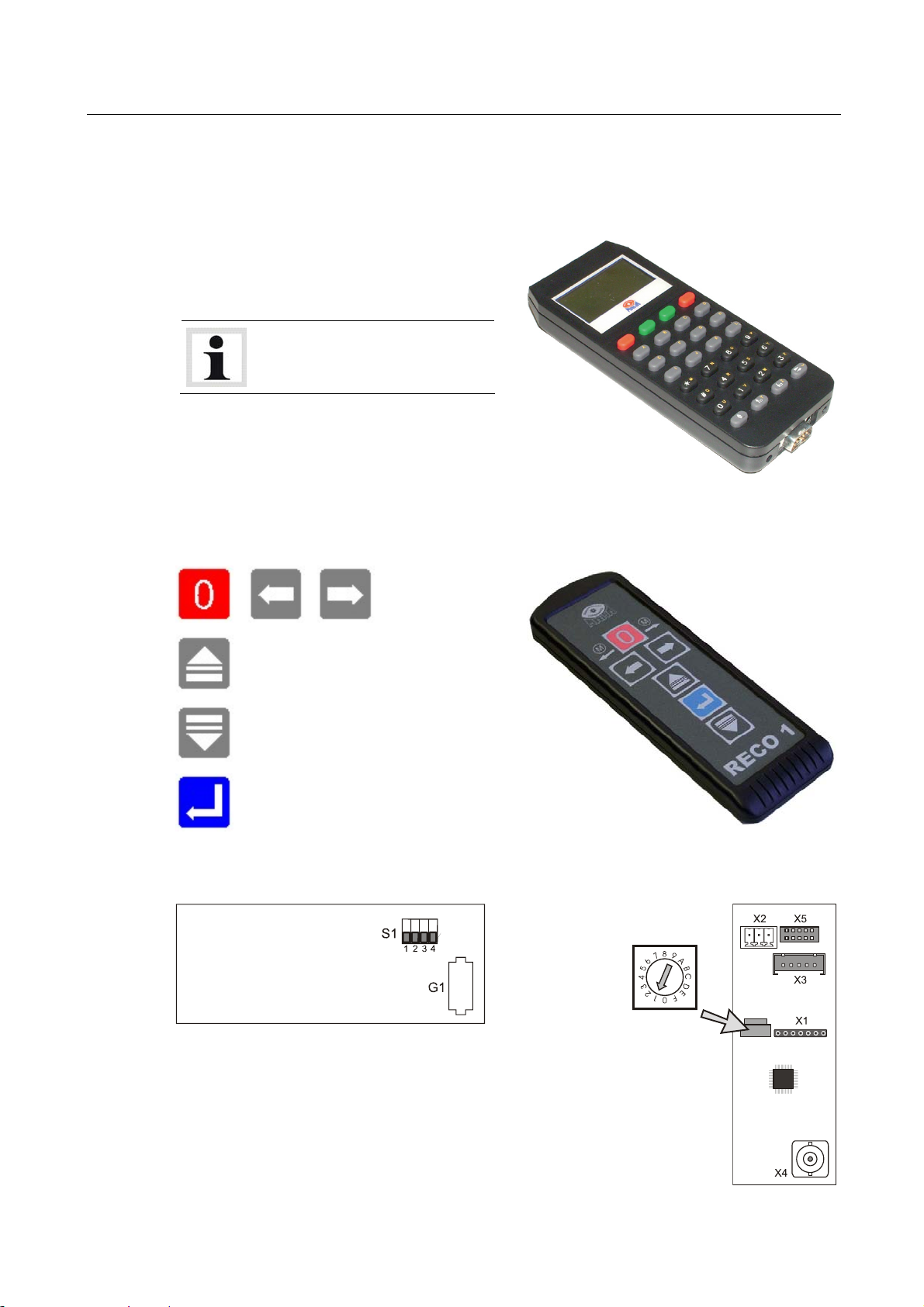
2.4.1 Infrared Remote Control IFB 3
Separate operating instructions
for the IFB 3 are available.
7
2.4.2 Radio Remote Control RECO 1
Not used
Menu item upwards
Menu item downwards
Confirm
Transmitter
Radio Module HLE
Receiver
Battery G1:
Typel: "CR 2032" 3 V Lithium
DIP Switch S1:
See next page for channel setting.
Rotary coding
switch for
channel selection
BA260401-en
8
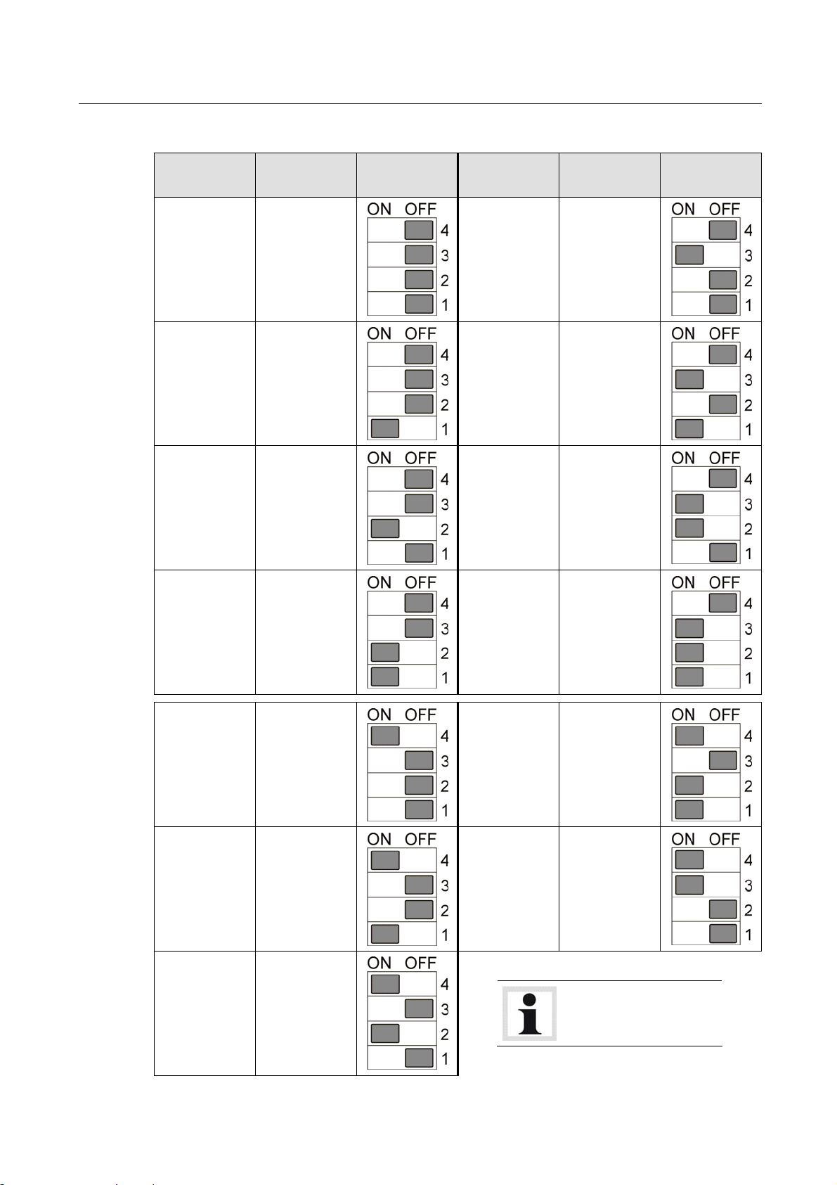
Transmission
Channel
Frequency
in MHz
0 868.000
1 868.200
2 868.400
DIP Switch
Setting
Transmission
Channel
Frequency
in MHz
DIP Switch
Setting
4 868.800
5 869.000
6 869.200
3 868.600
8 870.000
9 868.300
10 868.950
7 869.800
11 869.525
12 869.850
Do not use transmission channels 8…12!
BA260401-en
 Loading...