

MAHA TWIN F IV 3.0, TWIN F IV 3.0 A, TWIN F IV 3.0 U, TWIN F IV 3.5, TWIN F IV 3.5 A Original Operating Instructions
...Page 1
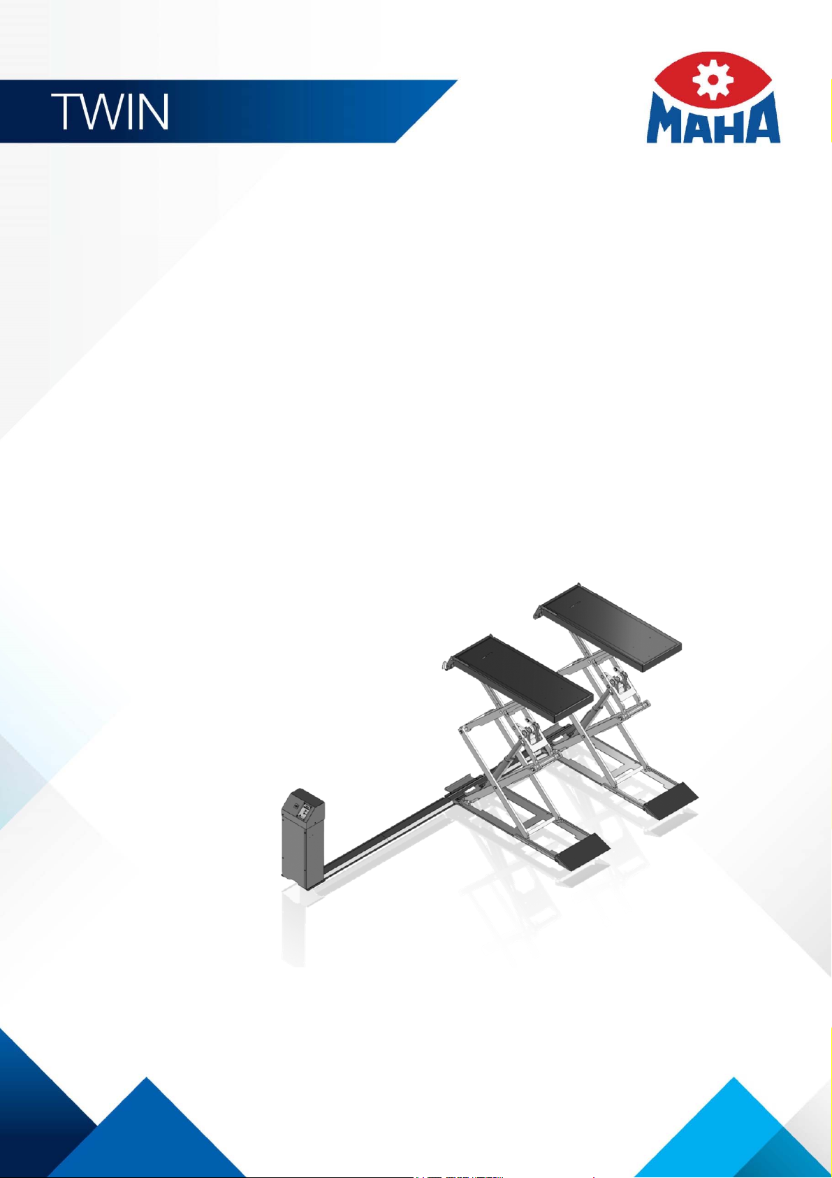
TWIN F IV 3.0 | 3.5
Scissors Lift
Original Operating Instructions
BA083101-en
Pos: 1 /Technische Dokumentation/Alle Geräte/ Titeltexte/Titel text: TWIN F IV Alle @ 35\mod_1389 950928631_0.doc x @ 1874819 @ @ 1
TWIN F IV 3.0 A
TWIN F IV 3.0 U
TWIN F IV 3.5 A
TWIN F IV 3.5 U
Pos: 2 /Technische Dokumentation/Hebetechnik/ TWIN/083101 TWIN F IV 3.5/BA/Inha lt: 0831 Titelbild @ 42\mo d_1435313868549_0.do cx @ 2262454 @ @ 1
Pos: 3 /-----Format-----/MANUELLER UMBRUCH Seitenumbruc h @ 0\mod_1134403577687_0.d ocx @ 1277 @ @ 1
Fehler! Verwenden Sie die Registerkarte 'Start', um Name dem Text zuzuweisen, der hier angezeigt werden soll.Fehler! Verwenden Sie
die Registerkarte 'Start', um Name dem Text zuzuweisen, der hier angezeigt werden soll.Fehler! Verwenden Sie die Registerkarte
'Start', um Name dem Text zuzuweisen, der hier angezeigt werden soll.
Page 2

2
Pos: 4 /-----For mat---- -/Inh altsv er zeic hn is - 3 Ebe nen @ 5\mod _116 88674 41046_ 75.d ocx @ 72 920 @ @ 1
Contents
1 Safety ...................................................................................................................... 5
1.1 Introduction ......................................................................................................................................... 5
1.2 Symbols .............................................................................................................................................. 5
1.3 Intended Use ....................................................................................................................................... 5
1.4 Inappropriate Use ................................................................................................................................ 5
1.5 Requirements on Operating and Service Personnel ............................................................................. 5
1.6 Safety Instructions for Commissioning ................................................................................................. 6
1.7 Safety Instructions for Operation ......................................................................................................... 6
1.8 Safety Instructions for Servicing ........................................................................................................... 8
1.9 Safety Instructions for Handling Hydraulic Fluid ................................................................................... 8
1.10 Additional Safety Instructions for Lifts with Transport Frame for Mobile Use ........................................ 9
1.11 What to Do in the Event of Defects or Malfunctions ........................................................................... 10
1.12 What to Do in the Event of an Accident ............................................................................................. 10
2 Description ............................................................................................................. 11
2.1 General Information ........................................................................................................................... 11
2.2 Specifications .................................................................................................................................... 11
2.3 Sample Nameplate ............................................................................................................................ 13
3 Transport and Storage ........................................................................................... 14
4 Installation and Initial Operation .............................................................................. 14
5 Operation ............................................................................................................... 15
5.1 Main Switch....................................................................................................................................... 15
5.2 Controls and Indicators ..................................................................................................................... 15
5.3 Display Codes ................................................................................................................................... 16
5.4 Saving and Deleting the Maximum Lifting Height ............................................................................... 16
5.5 Driving onto the Lift ........................................................................................................................... 17
5.6 Using Support Blocks........................................................................................................................ 17
5.6.1 Stacking Two Blocks on Top of Each Other ...................................................................................... 20
5.7 Raising and Lowering ........................................................................................................................ 20
5.8 Adjusting the Ramp ........................................................................................................................... 21
5.9 Bleeding the Hydraulic System .......................................................................................................... 21
5.10 Manual Lowering ............................................................................................................................... 21
5.11 Lift with Transport Frame for Mobile Use ........................................................................................... 22
6 Maintenance .......................................................................................................... 24
6.1 Maintenance Schedule ...................................................................................................................... 24
6.2 Care Instructions ............................................................................................................................... 24
6.3 Annual Inspection .............................................................................................................................. 25
6.4 Checking the Fluid Level .................................................................................................................... 25
6.5 Troubleshooting ................................................................................................................................ 26
6.6 Spare Parts ....................................................................................................................................... 26
BA083101-en
Page 3

3
7 Service Lifetime ...................................................................................................... 27
8 Dismantling ............................................................................................................ 27
9 Disposal ................................................................................................................. 27
10 Contents of the Declaration of Conformity .............................................................. 27
11 Company Information ............................................................................................. 28
Pos: 5 /-----For mat---- -/MAN UELLER UMBRUCH S eitenumb ruch @ 0\m od_11 34403 5776 87_0.d ocx @ 1 277 @ @ 1
BA083101-en
Page 4

4
Pos: 6 /-----For mat---- -/MAN UELLER UMBRUCH S eitenumb ruch @ 0\m od_11 34403 5776 87_0.d ocx @ 1 277 @ @ 1
BA083101-en
Page 5
5
1
Safety
1.1
Introduction
1.2
Symbols
1.3
Intended Use
1.4
Inappropriate Use
1.5
Requirements on Operating and Service Personnel
Pos: 7 /Tec hnisc he Dokum entati on/All e Geräte/ Über schrifte n/Übersc hriften 1/S/ Überschr ift 1: Sich erheit @ 6\mod_1174482399906_75.docx @ 76962 @ 2 @ 1
Pos: 8 /Technisc he Dokum enta tion/ All e Gerä te/ Übers chrif ten/Üb ersc hrift en 1 .1/E/ Übers chr ift 1.1: E inführ ung @ 6\m od_1174482219062_75.docx @ 76793 @ 2 @ 1
Pos: 9 /Technisc he Dokum enta tion/ All e Gerä te/In halte/ Sic herhe it/In halt : Ei nführ ung S icher hei t_12p t @ 2 5\mod_1324455248318_75.docx @ 1138886 @ @ 1
Thoroughly read this manual before operating the equipment and comply with the
instructions. Always display the manual in a conspicuous location.
Personal injury and property damage incurred due to non-compliance with these
Pos: 10 /Technische Dokume ntatio n/Alle Geräte/ Übersc hriften/ Überschr iften 1.1/S/ Übersc hrift 1.1: Symb ole @ 6\mod_1174482270875_75.docx @ 76865 @ 2 @ 1
Pos: 11 /Technische Dokume ntatio n/Alle Geräte/ Inhalte/ Sicher heit/In halt: Sy mbo le Sicher heit_1 2pt @ 25\mod_1324456650897_75.docx @ 1139046 @ @ 1
safety instructions are not covered by the product liability regulations.
Important safety instructions. Failure to comply with instructions could result in
personal injury or property damage.
Important information.
Pos: 12 /Techn ische Dokume ntation/Al le Geräte/Übers chriften/ Überschrifte n 1.1/B/Über schrift 1.1: Bes timmungsg emäßer Gebrau ch @ 6\mod_ 1176 73402 2203_ 75.docx @ 8874 6 @ 2 @ 1
Pos: 13 /Technische Dokume ntatio n/Hebet echnik /00 HBZ Alle/I nhalte/I nhalt: Bestim mungs gemäßer Gebr auch HBZ _12p t @ 29\m od_1351147628024_75.docx @ 1668694 @ @ 1
• This lift shall be used exclusively for the safe lifting of motor vehicles. Observe
the rated load capacity and load distribution.
• The lift shall not be modified without the express written consent of the
manufacturer. In case of non-compliance the declaration of conformity
Pos: 14 /Technische Dokume ntatio n/Hebet echnik /08 Sc heren-H ebeb ühn en/ 26 01 T WIN F II I 3. 0 / 4.0/ BA/ Inha lt: 082 6 B est immu ngs gemä ßer G ebr auch E rg änzung _12p t @ 26\mod_1326702134892_75.docx @ 1505717 @ @ 1
becomes void.
• The lift can be re-positioned on-site adhering to the mandatory ambient
Pos: 15 /Technische Dokument ation/Alle Gerät e/Übersc hriften/Üb erschriften 1. 1/B/Übers chrift 1.1: Bes timm ungsw idr iger Gebr auch @ 18\ mod_1255530265027_75.docx @ 471571 @ 2 @ 1
Pos: 16 /Technische Dokume ntatio n/Hebet echnik /00 HBZ Alle/I nhalte/I nhalt: Best immungsw idrig er Gebr auch H BZ_12pt @ 2 6\mod_1325512462855_75.docx @ 1143595 @ @ 1
conditions.
Any use other than described is inappropriate, for example:
• Climbing on the lift supports
• Transporting persons on the lift supports
Pos: 17 /Technische Dokume ntatio n/Alle Geräte/ Übersc hriften/ Überschr iften 1.1/A/ Übersc hrift 1.1: Anf order ungen a n das Bedien ungs- und Serv iceper sonal @ 34\mod_1380637497630_75.docx @ 1835413 @ 2 @ 1
Pos: 18 /Technische Dokume ntatio n/Alle Geräte/ Inhal te/Si cher heit/I nhal t: Anf ord erun gen a n das Bed ienu ngs- u nd Servi cepers onal_1 2pt @ 4 7\mod_1482392891402_75.docx @ 2803198 @ @ 1
• Usage as mobile work platform or for other lifting operations
All persons employed in the operation, maintenance, installation, removal and
disposal of the device must
• be mentally and physically suited for these activities,
• be at least 18 years old,
BA083101-en
Page 6

6
1.6
Safety Instructions for Commissioning
1.7
Safety Instructions for Operation
• be trained and instructed in writing,
• have read and understood the operating instructions, especially the instructions
what to do in the event of defects or malfunctions,
• be on record as having been instructed in safety guidelines,
• have practical experience in working with vehicle lifts and the hazards inherent
Pos: 19 /Technische Dokument ation/Alle Gerät e/Übersc hriften/Üb erschriften 1. 1/S/Übersc hrift 1.1: Siche rheit svor schr iften f ür d ie I nbetr ieb nahm e @ 6\m od_1174482269156_75.docx @ 76838 @ 2 @ 1
Pos: 20 /Technische Dokume ntatio n/Hebet echnik /00 HBZ Alle/I nhalte/I nhalt: Sicher heitsv orschrif ten f ür die I nbetrieb nahme HBZ_12pt @ 47\mod_1483524035338_75.docx @ 2804458 @ @ 1
in such equipment.
• The lift shall be installed and commissioned by authorised service personnel
only.
• Use personal protective equipment.
• All safety features must be checked for proper function at commissioning.
• The control desk (if present) shall not be installed in the danger zone of the lift.
• The standard lift version shall not be installed and commissioned in hazardous
locations, outdoors, in moist rooms (e.g. car wash) or outside a temperature
Pos: 21 /Technische Dokume ntatio n/Alle Geräte/ Übersc hriften/ Überschr iften 1.1/S/ Übersc hrift 1.1: Sic herheit svorschr iften f ür den Betri eb @ 6\m od_1174482268953_75.docx @ 76826 @ 2 @ 1
range of 5…40 °C (41…104 °F).
Pos: 22 /Tec hn isch e Do kume ntatio n/Hebet echnik/ 00 HBZ Alle/I nhalte/I nhalt: Sicher heitsv orschrif ten f ür den Betrieb H BZ_1 2pt @ 47\mod_1484658648165_75.docx @ 2810948 @ @ 1
• Observe the detailed operating instructions.
• Observe all accident prevention regulations.
• Use personal protective equipment.
• The standard lift version shall not be operated in hazardous locations, outdoors,
in moist rooms (e.g. car wash) or outside a temperature range of 5…40 °C
(41…104 °F).
• To ensure safe operation, check the functionality of all safety devices before
using the lift.
• The control desk (if present) must be positioned in such a way that there is an
unobstructed view to the complete working area and the emergency stop can
be accessed at all times.
• All structural parts of the equipment must be visually checked at regular
intervals.
• Supply of suitable illuminating devices is the owner's/operator's responsibility.
• Do not allow anyone to stay in the danger zone when driving on or off the lift.
• Lifts with cylinder and runways: when lifting vehicles with a short wheelbase,
make sure that one axle is in front of the lifting cylinder, the other behind it.
• Lifts with wheel-free jack: before driving on or off the lift or wheel-free jack,
make sure the jack is in bottom position.
• If the operator is unable to see all parts of the danger zone, a trained second
person must monitor such areas.
BA083101-en
Page 7

7
• Center the vehicle on the lift when it is in fully lowered position.
• After positioning the vehicle on the lift secure it against roll-off.
• Lifts with runways: make sure the vehicle tyres do not contact the roll-off
protection when raising or lowering the lift.
• Lifts with runways: modifications (such as usage of extensions) are permissible
only under the condition that the functionality of the roll-off protection is
maintained (protective position of ≥ 0.1 m above the runways).
• The load rating on the identification plate must not be exceeded.
• Keep the path of movement free of obstructions.
• Only use the vehicle manufacturer's recommended lift points.
• Only use lifting supports approved by the vehicle manufacturer.
• The vehicle must be lifted as a whole. usage of external hoisting and support
devices in combination with the lift must be approved by the manufacturer.
• Do not use the lift for transporting persons.
• Lifts with support arms or wheel-free jack: when raising the lift, all support
points at the vehicle body must be engaged at the same time.
• Lifts with support arms or swing arm jack: use one additional extender or one
support block only for each support point.
• Lifts with support arms or swing arm jack: check arm restraints for secure
engagement as soon as support arms contact vehicle lift points.
• Lifts with wheel-free jack: secure engagement of the vehicle must be ensured
by using appropriate means (e.g. lashing straps).
• After raising the vehicle briefly, stop and check the lift supports for secure
contact.
• Make sure the vehicle doors are closed during raising and lowering cycles.
• Make sure the parking brake is applied during raising and lowering cycles.
• Closely watch lift and vehicle during raising and lowering cycles.
• Do not allow anyone to stay in lift area during raising and lowering cycles.
• Lifts with support arms or wheel-free jack: after setting down the vehicle, check
the lift supports for secure contact before raising the vehicle again.
• Axle lift (if present): observe the installation instructions. Use both hands when
moving the axle lift. The axle lift must be in park position during raising and
lowering cycles.
• Axle lift (if present): the vehicle must be additionally secured against rolling off
while one axle is in a raised position.
• Do not allow anyone to climb up the lift or the raised vehicle.
• Before leaving the lift, fully lower the vehicle or secure it against accidental
lowering.
• Keep lift and vehicle free of tools and parts.
• Keep the lift and lift area clean. Risk of slippage on oily floors!
BA083101-en
Page 8

8
1.8
Safety Instructions for Servicing
1.9
Safety Instructions for Handling Hydraulic Fluid
• The main switch serves as emergency stop switch. In case of emergency turn it
to "0".
• Protect the lift against unauthorized usage by padlocking the main switch.
• Protect all parts of the electrical equipment from humidity.
• Use caution with operating vehicle engines. Danger of poisoning!
• When removing heavy vehicle components, the centre of gravity can change. In
such circumstances appropriate action must be taken as required.
• Residual risk: Tripping over runways of surface mounted lifts, tripping over
Pos: 23 /Technische Dokume ntatio n/Alle Geräte/ Übersc hriften/ Überschr iften 1.1/S/ Übersc hrift 1.1: Sic herheit svorschr iften f ür Serv icearbe iten @ 6\mod_ 117 4482270640_75.docx @ 76850 @ 2 @ 1
Pos: 24 /Technische Dokume ntatio n/Hebet echnik /00 HBZ Alle/I nhalte/I nhalt: Sicher heitsv orschrif ten f ür Servic earbei ten HBZ _1 2pt @ 46\mod_1481283945452_75.docx @ 2797338 @ @ 1
tools.
• Use personal protective equipment.
• Service work must be done by authorized service technicians.
• Turn off and padlock the main switch before doing any repair, maintenance or
setup work.
• The system must be unpressurized during maintenance work.
• Work on pulse generators or proximity switches must be done by authorized
service technicians.
• Work on the electrical equipment must be done by service technicians or
qualified electricians.
• Ensure that ecologically harmful substances are disposed of in accordance with
the appropriate regulations.
• Do not use high pressure or steam jet cleaners. Do not use caustic cleaning
agents.
• The lift's safety devices must be set by authorized service technicians.
Pos: 25 /Tec hn isch e Do kume ntatio n/Alle Geräte/ Übersc hriften/ Überschr iften 1.1/S/ Übersc hrift 1.1: Sic herheit svorschr iften f ür den Umga ng mi t Hydrau liköl @ 1 6\mod _1 24660 77295 23_75.d ocx @ 4 01284 @ 2 @ 1
Pos: 26 /Tec hn isch e Do kum ent atio n/Alle G eräte/I nhalte/S icher heit/In halt: Si cherhei tsvorsc hriften für de n Umg ang m it Hydrau liköl_ 12pt @ 25\mod_1324456399127_75.docx @ 1139012 @ @ 1
• Do not replace or override the safety devices.
• Neutralize hydraulic fluid spills with binder.
• Remove contaminated clothing immediately.
• Inhalation: If symptoms persist, seek medical treatment.
• Skin contact: Wash skin immediately with soap and water. If skin irritation
persists, seek immediate medical advice.
• Eye contact: Rinse thoroughly with water and seek medical advice.
• Ingestion: Do not induce vomiting. Seek immediate medical attention.
Pos: 27 /Technische Dokume ntatio n/Alle Geräte/ Übersc hriften/ Überschr iften 1.1/Z /Überschr ift 1. 1: Zusä tzlich e Sic h.vorschr iften f ür d ie H eb. mi t Ge stel l für mobi len E insa tz @ 16\mod_1248965750447_75.docx @ 422801 @ 2 @ 1
BA083101-en
Page 9

9
1.10
Additional Safety Instructions for Lifts with Transport Frame for Mobile Use
Pos: 28 /Technische Dokume ntatio n/Hebet echnik /08 Sc heren-H ebebü hnen/ 26 01 TWI N F III 3. 0 / 4.0/B A/Inha lt: 082 6 Zusä tzlic he S icherh eits vorsc hrift en TWIN F II I mob il_ 12pt @ 2 8\mod_1333531948317_75.docx @ 1578057 @ @ 1
• The lift shall not be exposed to direct, external weather conditions (snow, rain,
etc.).
• The lift shall not be erected, stored and commissioned in explosion- and fire-
endangered operating halls or in moisture-endangered rooms (wash halls).
Above and beyond this, storage is only allowed in enclosed rooms.
• The lift shall only be positioned and operated on an even surface.
• The maximum permissible inclination of the surface is 2 %.
• The underground surface shall be paved (cement, blacktop) and have sufficient
solidity to bear the load of the pressure forces that are created.
• The static friction between the underground and the lift contact surface shall be
sufficient to prevent sudden slipping. The lift shall not be used on snowcovered, icy underground surfaces. The lift shall not be positioned and
operated on surfaces which have been contaminated with oil, gasoline or
lubricants.
• It is forbidden to operate the lift on unpaved surfaces (e.g. grass, gravel etc.).
• Clean up the underground surface which may endanger the solid stance of the
lift before erection (e.g. gravel, stones).
• No objects (wooden boards etc.) shall be laid under the lift to compensate for
uneven surfaces. In this case, another, safer erection spot shall be chosen.
• The lift’s erection surface shall be cleared and kept clean of any objects sticking
to it or any other impurities (gravel, oil).
• Before lifting a vehicle, the lift stability shall be checked by the operating
personnel.
• Vehicles shall only be lifted if the lift has been removed from the transport unit
(forklift, brakable dolly).
• An additional stroke length extension or lifting of the loaded lift is forbidden.
• The lift shall only be moved with suitable lifting and transport devices (ground
conveyor). The supports of the lifting and transport units shall fit to the supplied
transport frame. Only forklifts and dollies designed to meet valid machinery
directives shall be used.
• The forks of the used lifting and transport unit (ground conveyor) shall be
placed at least 1000 mm deep in the transport frame.
• The lift shall only be lifted using the transport frame. A different form of lifting is
not allowed.
• The proper securing of the operating unit for transport shall be done as shown
in the operating manual.
• The operating unit shall only be transported in the shown position.
• During transport the side of the control cabinet with a label attached to it shall
be in an up position.
BA083101-en
Page 10

10
1.11
What to Do in the Event of Defects or Malfunctions
1.12
What to Do in the Event of an Accident
• Immediately after transport the control cabinet shall be placed in an upward
position. The lift shall not be stored with the control cabinet in a horizontal
position.
• Only one lift shall be transported at a time.
• The lift shall only be transported in its retracted position.
• The supplied retaining bracket shall be attached for the lift transport.
• No other objects shall be placed and/or transported on the lift during transport.
• The valid accident prevention and safety regulations of the respective transport
device shall be adhered to for the load security and transport.
• Movable forks which are part of the transport unit shall be locked.
• Only lifting and transport units (e.g. manual dolly, forklift) with driving and
parking brakes for controlled driving shall be used.
• The lifting and transport unit shall have a load capacity of at least 1000 kg.
• Using manual force the lift shall only be moved on an even surface (maximum
inclination 2 %).
• Secure the lift against unintended movement using the parking brake if it
• It is prohibited to move the lift on slippery (e.g. snow-covered) ground.
• When moving the lift or during normal operation never pinch or kink the
• Never drive over the hoses with a vehicle, dolly etc.
• No objects shall be placed on the hoses.
Pos: 29 /Technische Dokume ntatio n/Alle Geräte/ Überschrift en/Überschr iften 1.1/V /Überschr ift 1.1: Verhalten im Störfall @ 6\mod_1178097008375_75.docx @ 90829 @ 2 @ 1
Pos: 30 /Technische Dokume ntatio n/Hebet echnik /00 HBZ Alle/I nhalte/I nhalt: Ver halte n im Stör fall H BZ_12p t @ 26\mod_1325513682583_75.docx @ 1143723 @ @ 1
• Damaged or leaking hoses shall be replaced immediately.
• In case of defects or malfunctions such as uncontrolled lift movement or
• Turn off the main switch and secure it against unauthorized usage. Contact
Pos: 31 /Technische Dokume ntatio n/Alle Geräte/ Übersc hriften/ Überschr iften 1.1/V /Übersc hrift 1 .1: Ver halten bei U nfällen @ 19\m od_12 67177 2453 37_7 5.docx @ 79460 0 @ 1 @ 1
Pos: 32 /Technische Dokume ntatio n/Alle Geräte/ Inhalte/ Sicher heit/In halt: V erhalt en bei Unfälle n_12p t @ 34\mod_1381128863435_75.docx @ 1837175 @ @ 1
• The injured person is to be removed from the danger area. Find out where
remains on the lifting and transport unit after transporting.
The lift shall not be stored for a longer time period in a raised position on the
transport unit.
hydraulic hoses.
deformation of the superstructure, support or lower the lift immediately.
service.
dressing and bandages are kept. Seek first-aid.
• Provide first-aid (stop bleeding, immobilise injured limbs), report the accident
and seal off the accident site.
• Immediately report any accident to your supervisor. Make sure a record is kept
of every occasion first-aid is provided, e.g. in an accident book.
Pos: 33 /-----For ma t-----/MA N UEL LER UMB RUC H Se ite num br uch @ 0\m od_1134403577687_0.docx @ 1277 @ @ 1
BA083101-en
• Remain calm and answer any questions that may arise.
Page 11

11
2
Description
2.1
General Information
2.2
Specifications
Pos: 34 /Technische Dokume ntatio n/Alle Geräte/ Übersc hriften/ Überschr iften 1/ B/Über schrift 1: Beschre ibung @ 6\mod_1174482271453_75.docx @ 76889 @ 2 @ 1
Pos: 35 /Technische Dokument ation/Alle Gerät e/Übersc hriften/Üb erschriften 1. 1/A/Übersc hrift 1.1: Allgem eines @ 6\mod_1182865005781_75.docx @ 97736 @ 2 @ 1
Pos: 36 /Technische Dokume ntatio n/Hebet echnik /08 Sc heren-Heb ebühn en/31 01 TWIN F IV 3 .5/BA/ Inhalt: 0831 Beschr eibun g Allgem eines @ 26\mod_1326702755205_75.docx @ 1505761 @ @ 1
This lift model is equipped with two support plates mounted to a scissors
structure. The drive system consists of four hydraulic cylinders with hydraulic
power unit. The lift is operated via an electric dead man's type control using
Pos: 37 /Technische Dokume ntation/Al le Geräte/Übers chriften/ Überschrif ten 1.1/T/Über schrift 1.1: Technische Daten @ 7\mod_1184075526343_75.docx @ 99711 @ 2 @ 1
Pos: 38 /Technische Dokume ntatio n/Hebet echnik /08 Sc heren-Heb ebühn en/31 01 TW IN F IV 3.5/ BA/ Inh alt: 083 1 Te chn isc he Date n ( Tabe lle) @ 3 5\mod_1389950621407_75.docx @ 1874863 @ @ 1
pushbuttons, synchronization is achieved through a cable control system.
3.0 A 3.5 A
Fuse (time-delay) 16 A
Working temperature range 5…40 °C
Support plate width 605 mm
Support plate length 1550 mm
Support plate length max. 2100 mm
Working pressure, hydraulic 260 bar
Overall width (recommended) 1955 mm
Shipping weight 800 kg
Lifting height max. 1900 mm
Raising time, load-dependent approx. 40 s
Hydraulic power unit 3.6 kW
Hydraulic fluid qty. 9 l
Noise emission < 70 dB(A)
Mains frequency 50 Hz
Mains voltage 400 V
Phases 3
Pinch point protection Audible warning signal
Lowering time, load-dep. approx. 40 s
Load capacity 3000 kg 3500 kg
Drive-over height 105 mm
Shipping dimensions W x H x L 750 x 700 x 1960 mm
BA083101-en
Page 12

12
3.0 U 3.5 U
Fuse (time-delay) 16 A
Working temperature range 5…40 °C
Support plate width 605 mm
Support plate length 1550 mm
Support plate length max. 2100 mm
Working pressure, hydraulic 260 bar
Installation depth 115 mm
Overall width (recommended) 2000 mm
Shipping weight 800 kg
Lifting height max. 1885 mm
Raising time, load-dependent approx. 40 s
Hydraulic power unit 3.6 kW
Hydraulic fluid qty. 9 l
Noise emission < 70 dB(A)
Mains frequency 50 Hz
Mains voltage 400 V
Phases 3
Pinch point protection Audible warning signal
Lowering time, load-dep. approx. 40 s
Load capacity 3000 kg 3500 kg
Shipping dimensions W x H x L 750 x 700 x 1960 mm
BA083101-en
Page 13

13
2.3
Sample Nameplate
Pos: 40 /Technische Dokument ation/Alle Gerät e/Übersc hriften/Üb erschriften 1. 1/T/Übers chrift 1.1: Type nschild-Mus ter @ 1 1\mod _122 76222 06096_ 75.d ocx @ 27 5574 @ 2 @ 1
Pos: 41 /Tec hn isch e Do kument ation/H ebetech nik/0 8 S chere n-Hebeb ühnen/ 0001 Sc heren-H ebebüh nen A lle/Inh alte/Inh alt: Ty pensch ild-Pos itio n TWIN_ 12pt @ 26\ mod_1326271006393_75.docx @ 1150623 @ @ 1
Lifts of this model series have one nameplate each at the control desk and on the
bottom side of both support plates. In the event of customer complaints, hotline
requests or spare parts orders, serial number and YoM of the lift should always be
indicated.
Pos: 42 /Technische Dokume ntatio n/Hebet echnik /08 Sc heren-Heb ebühn en/00 01 Scher en-Heb ebühne n Alle/ Inhal te/Inhal t: Typens child-M uster M AHA S chere n-HBZ @ 2 4\mod_1305811444728_75.docx @ 1010345 @ @ 1
SCISSORS LIFT
Ser. No. / Date of Production: ***
Project: ***
Model and Version: ***
Supply Voltage: ***
Frequency: ***
Rated Current: ***
Fuse Protection: ***
Load Capacity: ***
Pos: 43 /-----For ma t-----/MA N UEL LER UMB RUC H Se ite num br uch @ 0\m od_1134403577687_0.docx @ 1277 @ @ 1
BA083101-en
Page 14

14
3
Transport and Storage
4
Installation and Initial Operation
Pos: 44 /Technische Dokume ntatio n/Alle Geräte/ Übersc hriften/ Überschr iften 1/T/ Überschri ft 1: Transp ort und Lageru ng @ 20\mod_1268732488860_75.docx @ 826153 @ 1 @ 1
Pos: 45 /Technische Dokument ation/Alle Gerät e/Inhalte/ Inhalt: Tra nsport und La gerung_1 2pt @ 26\mod_1324468980166_75.docx @ 1141285 @ @ 1
Check package to ensure it is complete, in accordance with the order
confirmation. Report any transport damage to the carrier immediately.
During loading, unloading and transport always use suitable lifting equipment,
material handling equipment (e.g. cranes, forklifts, etc.) and the right load handling
attachments and slings. Always ensure that the parts to be transported are
suspended or loaded properly so that they cannot fall, taking into account size,
weight and the centre of gravity.
Store the packages in a covered area, protected from direct sunlight, at a low
humidity and with temperatures between 0...+40 °C (32…104 °F). Do not stack
packages.
When unpacking, take care to avoid any possibility of injury or damage. Keep at a
safe distance when opening the package strapping, do not allow any parts to fall
Pos: 46 /Technische Dokume ntatio n/Alle Geräte/ Übersc hriften/ Überschr iften 1/M/Üb ersc hrift 1: M ontag e und E rstinbe triebn ahme @ 18\mod_1255417443299_75.docx @ 463797 @ 1 @ 1
out.
Pos: 47 /Technische Dokume ntatio n/Hebet echnik /00 HBZ Alle/I nhalte/I nhalt: Mont age und Erstinb etriebn ahme HBZ_ 12pt @ 2 6\mod_1326110822610_75.docx @ 1149028 @ @ 1
Installation and commissioning of the equipment must be carried out by specially
trained personnel, authorised for the task. Specialist personnel includes
authorised, trained skilled staff from the manufacturer, the dealer and the relevant
Pos: 48 /-----For ma t-----/MA N UEL LER UMB RUC H Se ite num br uch @ 0\m od_1134403577687_0.docx @ 1277 @ @ 1
service partners.
BA083101-en
Page 15

15
5
Operation
5.1
Main Switch
5.2
Controls and Indicators
A LED Display: Operating Status
C Button: Lower
B Button: Raise
D Button:
E Main Switch
Pos: 49 /Technische Dokument ation/Alle Gerät e/Übersc hriften/Üb erschriften 1/ B/Überschri ft 1: Bedienung @ 6\mod_1174482271218_75.docx @ 76877 @ 1 @ 1
Pos: 50 /Technische Dokument ation/Alle Gerät e/Übersc hriften/Üb erschriften 1. 1/H/Überschr ift 1.1: Haup tschalter @ 6\mod _117 75928 58312_ 75.d ocx @ 90 635 @ 2 @ 1
Pos: 51 /Technische Dokume ntatio n/Hebet echnik /00 HBZ Alle/I nhalte/I nha lt: Ha upts chal ter m it N ot- Aus-Fu nktion H BZ_12pt @ 2 6\mod_1325575201603_75.docx @ 1144333 @ @ 1
The main switch is used as emergency switch. In case of emergency turn it to
position 0.
• Main switch in position 0: Power supply is interrupted
• Main switch in position 1: Lift is ready for operation
• When in position 0, the main switch can be protected against
tampering by means of a padlock.
Pos: 52 /Technische Dokume ntatio n/Alle Geräte/ Übersc hriften/ Überschr iften 1.1/B/ Überschrif t 1.1: Bedien- und Anzeigeelem ente @ 23\mod _1296 2203 01443_ 75.d ocx @ 96 8107 @ 2 @ 1
Pos: 53 /Technische Dokume ntatio n/Hebet echnik /08 Sc heren-Hebebühnen/3101 TWIN F IV 3.5/BA/Inhalt: 0831 Bedienelemen te (Bild) @ 25\mod_1318494199927_0.docx @ 1061976 @ @ 1
Pos: 54 /Technische Dokume ntatio n/Hebet echnik /08 Sc heren-Heb ebühn en/31 01 TWIN F IV 3 .5/BA/ Inhalt: 0831 Bediene lemen te (Tex t) @ 42\mod _1 435 920 9083 59_ 75.d ocx @ 2 265 180 @ @ 1
The operating status is indicated by
red, yellow and green LEDs. See also
section "Troubleshooting".
When this button is pushed, lift
lowers until button is released or
lower limit stop is reached.
When this button is pushed, lift raises
until button is released or upper limit
stop is reached.
Pos: 55 /-----For ma t-----/MA N UEL LER UMB RUC H Se ite num br uch @ 0\mod_1134403577687_0.docx @ 1277 @ @ 1
used for saving/deleting the
maximum lifting height
BA083101-en
Page 16

16
5.3
Display Codes
LED Code
5.4
Saving and Deleting the Maximum Lifting Height
Saving the Maximum Lifting Height
1
2
3 +
Deleting the Maximum Lifting Height
1
2 +
Pos: 56 /Technische Dokument ation/Alle Gerät e/Übersc hriften/Üb erschriften 1. 1/D/Überschr ift 1.1: Displ ay-Codes @ 20\mod _1270 0288 30605_ 75.d ocx @ 83 2653 @ 2 @ 1
Pos: 57 /Tec hn isch e Do kument ation/H ebetech nik/0 8 S chere n-Hebebühnen/3101 TWIN F IV 3.5/BA/Inhalt: 0831 LED-Code @ 28\mod_1334651063911_75.docx @ 1581653 @ @ 1
Lighting Flashing 4x --- Undervoltage
Lighting Flashing 5x --- Height offset too large
Lighting Flashing 6x --- Internal keyboard defective
Lighting
Pos: 58 /Technische Dokument ation/Alle Gerät e/Übersc hriften/Üb erschriften 1. 1/M/Übersc hrift 1 .1: Max imale H ubhö he speic hern u nd lösc hen @ 42\mod_1435921265464_75.docx @ 2265276 @ 2 @ 1
Pos: 59 /Technische Dokume ntatio n/Hebet echnik /08 Sc heren-Hebebühnen/3101 TWIN F IV 3.5/TH/Inhalt: 0831 Progra mmi eru ng - Max. H ubhöhe @ 42\mod_1435917033297_75.docx @ 2264986 @ @ 1
Optional, with software V2.26 and higher.
Position lift at desired height.
RED
YEL
LO
W
GRE
EN
--- --- Lighting Ready for operation
Flashing 8x
to 30x
--- Contact service
Main switch OFF.
Optional, with software V2.26 and higher.
Main switch OFF.
Pos: 60 /-----For ma t-----/MA N UEL LER UMB RUC H Se ite num br uch @ 0\m od_1134403577687_0.docx @ 1277 @ @ 1
Push and hold these buttons, then main switch ON.
Green LED flashing, maximum lifting height is saved.
Push and hold these buttons, then main switch ON.
Green LED flashing, maximum lifting height is deleted.
BA083101-en
Page 17

17
5.5
Driving onto the Lift
5.6
Using Support Blocks
Pos: 61 /Technische Dokument ation/Alle Gerät e/Übersc hriften/Üb erschriften 1. 1/B/Übers chrift 1.1: Be fahre n @ 6\mod _1180 6074 97703_ 75.d ocx @ 94 502 @ 2 @ 1
Pos: 62 /Technische Dokume ntatio n/Hebet echnik /08 Sc heren-H ebeb ühn en/ 26 01 T WIN F II I 3. 0 / 4.0/ BA/ Inha lt: 082 6 W arnu ng - Befahren _12pt @ 26\mod_1326703265357_75.docx @ 1505893 @ @ 1
1 Make sure the ramps are locked
before driving onto the lift!
3 Observe correct approach direction!
Do not engage the vehicle
perpendicular to lift!
Pos: 63 /Technische Dokume ntatio n/Alle Geräte/ Übersc hriften/ Überschr iften 1.1/A/ Übersc hrift 1.1: Auf nahmek lötze v erwe nden @ 44\mod_1459263520420_75.docx @ 2427031 @ 2 @ 1
Pos: 64.1 /Technisch e Dokum entat ion/Heb etech nik/00 H BZ Al le/Inhal te/Inha lt: Aufna hmek lötze H BZ - V orgehe nswe ise (Tex t) @ 44\mod_1461682559816_75.docx @ 2437527 @ @ 1
1 The support blocks are approved for usage on lifts with a rated load capacity of
3,500 kgs.
2 Always use four original MAHA support blocks of identical size and shape.
3 Do not use support blocks with cracks, broken-off pieces or other damage.
4 Check that all support blocks and rubber pads are free of oil, grease, dirt or
debris.
5 Place the support blocks under the vehicle manufacturer‘s recommended lift
points.
2 Approach and exit the lift very slowly!
The chassis of low vehicles may hit
the floor.
6 Note correct positioning of the support blocks.
7 Raise the vehicle until the tyres clear the floor. Stop and recheck the lift
Pos: 64.2 /----- Form at-----/ MAN UE LLE R UM BR UCH Seit en umb ruch @ 0\mod_1134403577687_0.docx @ 1277 @ @ 1
supports for secure contact with the vehicle body.
BA083101-en
Page 18

18
A C B B A
C
Pos: 64.3 /Technisch e Dokum entat ion/Heb etech nik/00 H BZ Al le/Inhal te/Inha lt: Aufna hmek lötze H BZ - Z ulässi ger Berei ch (Tex t) @ 44\m od_1459257598516_75.docx @ 2426593 @ 3 @ 1
The support block must be placed fully on the surface without extending byond
the edges.
A Extension B Support surface; available are:
C Support block
Pos: 64.4 /Technisch e Dokum entat ion/Heb etech nik/00 H BZ Al le/Inhal te/Inha lt: Aufna hmek lötze H BZ - Z ulässi ger Berei ch (Bi lder) @ 44\mod_1459255428157_0.docx @ 2425779 @ @ 1
– Granulate coating
– Granulate foil
– Rubber plate
Pos: 64.5 /----- Forma t-----/M AN UEL LER UM BR UCH S eit en umb ruch @ 0\ mod_1134403577687_0.docx @ 1277 @ @ 1
BA083101-en
Page 19

19
a
a
b
Pos: 64.6 /Technisch e Dokum entat ion/Heb etech nik/00 H BZ Al le/Inhal te/Inha lt: Aufna hmek lötze H BZ - Diagonal (Text) @ 44\mod_1459259263636_75.docx @ 2426639 @ 3 @ 1
Diagonal positioning is permissible only with granulate coated surfaces (a). If
Pos: 64.7 /Technisch e Dokum entat ion/Heb etech nik/00 H BZ Al le/Inhal te/Inha lt: Aufna hmek lötze H BZ - D ia gonal (B ild er) @ 4 4\mod _145 92566 09357_ 0.d ocx @ 242 5825 @ @ 1
knobbly pads are used, these must mesh with the support blocks (b).
Pos: 64.8 /----- Form at-----/ MAN UE LLE R UM BR UCH Seit en umb ruch @ 0\mod_1134403577687_0.docx @ 1277 @ @ 1
BA083101-en
Page 20

20
5.6.1
Stacking Two Blocks on Top of Each Other
5.7
Raising and Lowering
Pos: 64.9 /Technisch e Dokum entat ion/Heb etech nik/00 H BZ Al le/Inhal te/Inha lt: Aufna hmek lötze H BZ - Sta pe ln (T ext) @ 4 4\mod_1459262938946_75.docx @ 2426985 @ 3 @ 1
Only the “DUO“ hard rubber blocks (VZ 975074) and the ductile plastic blocks (VZ
970045) may be stacked on top of each other, but not more than two blocks per
Pos: 64.10 /Te chnis che D okum enta tion/H ebe techn ik/ 00 HBZ All e/Inha lte/ Inha lt: A ufnahm ekl ötze H BZ - Stap eln (B ilder ) @ 44\mod_1459252038981_0.docx @ 2424947 @ @ 1
lifting point.
Pos: 65 /Technische Dokume ntatio n/Alle G eräte/ Übersc hriften/ Überschr iften 1.1/H/ Überschr ift 1 .1: Hebe n und Senke n @ 6\mod_1178521944593_75.docx @ 91237 @ 2 @ 1
Pos: 66 /Technische Dokume ntatio n/Hebet echnik /08 Sc heren-Heb ebühn en/3101 TWIN F IV 3.5/BA/Inhalt: 0831 Heben und Senken @ 26\mod_1326703330307_75.docx @ 1505937 @ @ 1
1 Turn the main switch to position 1.
• Lift is ready for operation.
2 Push and hold the RAISE button until the lift reaches the desired height.
• Lift stops once button is released or upper limit stop is reached.
3 Push and hold the LOWER button until the lift reaches the desired height.
• Lift stops once button is released or CE-Stop is reached.
4 To lower the lift completely, release the LOWER button and push it again.
• The remaining lift travel to the lower limit stop is accompanied by an audible
indicator.
Risk of injury!
Before lowering the lift to bottom position, verify that there are no persons or
obstructions in the danger area.
Pos: 67 /Technische Dokume ntation/Al le Geräte/Übers chriften/ Überschrif ten 1.1/R/Üb erschrift 1.1: Ramp e verstellen @ 25\mod_1318495325701_75.docx @ 1062076 @ 2 @ 1
BA083101-en
Page 21

21
5.8
Adjusting the Ramp
5.9
Bleeding the Hydraulic System
5.10
Manual Lowering
+C-M2
+C-M1.A
+C-M1.B
+C-M2
1
2
Pos: 68 /Technische Dokume ntatio n/Hebet echnik /08 Sc heren-Heb ebühn en/3101 TW IN F IV 3.5/ BA/ Inh alt: 0 831 Ramp e v erst elle n ( Bild ) @ 25\mod_1318495435846_0.docx @ 1062106 @ @ 1
Pos: 69 /Technische Dokume ntatio n/Hebet echnik /08 Sc heren-Hebebühnen/3101 TWIN F IV 3.5/ BA/ Inh al t: 0 831 Ramp e v ers telle n ( Tex t) @ 26\m od _132 670 339 293 7_75. d ocx @ 150 598 1 @ @ 1
1 Raise lever to unlock. 2 Lower the ramp.
Pos: 70 /Technische Dokume ntatio n/Alle Geräte/ Übersc hriften/ Überschr iften 1.1/H /Überschr ift 1 .1: Hy drauliksy stem e ntlüf ten @ 6\m od_1180531444046_75.docx @ 94390 @ 2 @ 1
Pos: 71 /Technische Dokume ntatio n/Hebet echnik /00 HBZ Al le/In halte/I nfo!/ In halt: Info - E nt lüftu n g dur ch S erv ice_ 1 2pt @ 26\m od_1326703449422_75.docx @ 1506025 @ @ 1
Bleeding of hydraulic system is done by authorized service technicians.
Pos: 72 /Technische Dokume ntatio n/Alle Gerät e/Über sc hrift en/Üb erschr ifte n 1. 1/M/ Übers chr ift 1 .1: Ma nuell es Ab senke n @ 6\mod_1178113285703_75.docx @ 90869 @ 2 @ 1
Pos: 73 /Technische Dokume ntatio n/Hebet echnik /00 HBZ Alle/I nhalte/ Warnu ng!/Inha lt: War nung - M anuel les Absen ken n ur durch gesch ultes Persona l_12pt @ 26\mod_1325584117708_75.docx @ 1145405 @ @ 1
Authorized personnel only! Do not restart the lift before the error has been
remedied.
Pos: 74 /Technische Dokume ntatio n/Hebet echnik /08 Sc heren-Heb ebühn en/3101 TWIN F IV 3.5/BA/Inhalt: 0831 Manuelles Absenken (Text) @ 28\mod_1333636779387_75.docx @ 1579389 @ @ 1
1 Mechanically disable
2 Push and hold
lowering.
and
.
together. Caution: Both sides are
3 While lowering, check both sides for synchronized operation. If the height offset
is too large, stop the lift and equalize by lowering the higher side. Then continue
with lowering procedure.
4 When the lift is in bottom position, re-enable
Pos: 75 /-----For mat -----/MAN UE LLE R UM BR UCH Se iten umb ruc h @ 0\mod_1134403577687_0.docx @ 1277 @ @ 1
.
BA083101-en
Page 22

22
5.11
Lift with Transport Frame for Mobile Use
Transport Preparation
Pos: 76 /Technische Dokume ntatio n/Alle Geräte/ Übersc hriften/ Überschr iften 1.1/H /Überschr ift 1 .1: Heb ebühn e mit G estel l für mob ile n Einsa tz @ 16\m od_1248966031988_75.docx @ 422821 @ 2 @ 1
Pos: 77 /Technische Dokume ntatio n/Hebet echnik /08 Sc heren-H ebeb ühn en/ 26 01 T WIN F II I 3. 0 / 4.0/ BA/ Inha lt: 082 6 W arnu ng - S icherh eit Mob ilges tell b eachten_ 12pt @ 28\ mod_1333535410409_75.docx @ 1578481 @ @ 1
Pay close attention to section "Safety / Additional Safety Instructions for Lifts with
Transport Frame for Mobile Use"!
Pos: 78 /Technische Dokume ntatio n/Hebet echnik /08 Sc heren-Heb ebühn en/31 01 TWIN F IV 3.5/BA/Inhalt: 0831 Mobilgestell (Bilder) @ 36\mod_13974673156 93_0.d ocx @ 195 2609 @ @ 1
Pos: 79 /Technische Dokume ntatio n/Hebet echnik /08 Sc heren-H ebeb ühn en/ 26 01 T WIN F II I 3. 0 / 4.0/ BA/ Inha lt: 082 6 Mob il ges tell ( Tex t)_12p t @ 28\mod_1333535472498_75.docx @ 1578525 @ @ 1
1 Attach brackets (A) and (B) to the lift.
2 Securely connect brackets with screws (C) and nuts (D).
3 Place the operating unit on the mobile transport frame. Make sure that the label
is showing on top. Attach to transport frame with locking screws (E).
4 Drive the lifting forks of the ground conveyer into the openings (F). The lifting
Pos: 80 /Technische Dokume ntatio n/Hebet echnik /08 Sc heren-Hebebühnen/3101 TWIN F IV 3.5/BA/Inhalt: 0831 Tankverschluss wechseln (Text) @ 36\mod_1397658614145_75.docx @ 1980668 @ @ 1
BA083101-en
forks must engage the transport frame with a depth of at least 1000 mm!
Page 23

23
Changing the Filler Cap
without
with
Labels
For transport and storage use the filler cap
Pos: 81 /Technische Dokume ntatio n/Hebet echnik /08 Sc heren-Hebebühnen/3101 TWIN F IV 3.5/BA/Inhalt: 0831 Tankver sch luss we chse ln (B ild) @ 3 6\mod _13 97473 2261 70_0.d ocx @ 195 2654 @ @ 1
Pos: 82 /Technische Dokume ntatio n/Hebet echnik /08 Sc heren-H ebeb ühn en/ 26 01 T WIN F II I 3. 0 / 4.0/ BA/ Inha lt: 082 6 Mob il ges tell Auf kleb er ( Tex t)_ 12p t @ 28\mod_1333535570733_75.docx @ 1578569 @ @ 1
recommissioning the lift, screw on the filler cap
This label is located on the front and
rear edge of the transport frame.
(Warning symbol in accordance with
BGV A 8 W14, DIN 4844-2 D-W014).
breather filter (s. Fig.). Before
breather filter.
This label is located on the side part of
the operating unit. It must always be
showing on top during transport!
Explanation: Warning about tripping
danger
Pos: 83 /Technische Dokume ntatio n/Hebet echnik /08 Sc heren-H ebeb ühn en/ 26 01 T WIN F II I 3. 0 / 4.0/ BA/ Inha lt: 082 6 Mob il ges tell Auf kleb er ( B ilder ) @ 16\mod_1249027419252_0.docx @ 423070 @ @ 1
Pos: 84 /-----For ma t-----/MA N UEL LER UMB RUC H Se ite num br uch @ 0\m od_1134403577687_0.docx @ 1277 @ @ 1
BA083101-en
Page 24

24
6
Maintenance
6.1
Maintenance Schedule
Interval
Maintenance items
Procedure
Check fluid for soiling and aging, replace
6.2
Care Instructions
Pos: 85 /Technische Dokume ntatio n/Papier korb/ Übersc hriften/ Überschr ift 1: Instand haltu ng @ 1 1\mod _123 13187 36629 _75.d ocx @ 28 9550 @ 2 @ 1
Pos: 86 /Technische Dokume ntatio n/Alle Geräte/ Inhalte/ Warnu ng!/In halt: W arnung - Haup tscha lter aus bei I nst andhal tung_ 12pt @ 26\ mod_1324465229892_75.docx @ 1140563 @ @ 1
Danger! Electric shock hazard!
Before doing any maintenance work, turn off the main switch and protect it
against tampering.
Pos: 87 /Technische Dokume ntatio n/Alle Geräte/ Überschrift en/Überschr iften 1.1/I /Überschr ift 1.1: Instandhal tungsplan @ 11\m od_1231318919401_75.docx @ 289622 @ 2 @ 1
Pos: 88 /Technische Dokume ntatio n/Hebet echnik /08 Sc heren-Heb ebühn en/00 01 Scher en-He bebüh nen A lle/ Inhal te/Inhal t: Inst andhal tungsplan Scher en-HBZ_12pt @ 26\mod_1325753628788_75.docx @ 1147009 @ @ 1
3 months
Check fluid level, top up if necessary.
Check hydraulic system for leakage.
Hydraulic system
Check power unit for unusual noise
during operation, check fastening
screws for tight fit.
Slider tracks and sliding
surfaces of extensions
6 months Hydraulic fluid
12 months General inspection Check all components for damage.
6 years Pressure hoses Replace pressure hoses.
Pos: 89 /Technische Dokume ntatio n/Alle Geräte/ Übersc hriften/ Überschr iften 1.1/P/ Übersc hrift 1.1: Pfle gehinwe ise @ 15\m od_12 4591 22348 54_75. docx @ 39 5780 @ 2 @ 1
Pos: 90 /Technische Dokument ation/Alle Gerät e/Inhalte/ Inhalt: Pfleg ehinweise - Al le Geräte_12pt @ 2 6\mod_1324468886116_75.docx @ 1141252 @ @ 1
• Periodically clean the equipment and treat it with a care product.
• Repair damage to the paintwork immediately to prevent corrosion.
• Usage of caustic cleaning agents or high pressure and steam jet cleaners may
Pos: 91 /Technische Dokume ntatio n/Alle Geräte/ Inhalte/ Info!/I nhalt: I nfo - Pflegehinweise_12pt @ 26\mod_1324461215655_75.docx @ 1139602 @ @ 1
lead to equipment damage.
Regular care and maintenance is the key condition for functionality and long life
expectancy of the equipment!
Pos: 92 /-----For ma t-----/MA N UEL LER UMB RUC H Se ite num br uch @ 0\m od_1134403577687_0.docx @ 1277 @ @ 1
Grease slightly.
if necessary.
BA083101-en
Page 25

25
6.3
Annual Inspection
12 (twelve) months
6.4
Checking the Fluid Level
Pos: 93 /Technische Dokument ation/Papier korb/Über schriften/ Überschrif t 1.1: Jährliche Überp rüfung @ 6\mod _11 74482 24571 8_75.d ocx @ 76 817 @ 2 @ 1
Pos: 94 /Technische Dokume ntatio n/Alle Geräte/ Inhalte/ Info!/I nhalt: I nfo - J ährlic he Überpr üfung_1 2pt @ 25\mod_1324460481075_75.docx @ 1139412 @ @ 1
• The maintenance interval prescribed by the manufacturer is
This maintenance interval refers to normal workshop usage. If the equipment is
used more frequently or under severe operating conditions (e.g. outdoors), the
interval must be reduced accordingly.
• Maintenance work shall be done only by authorized and trained service
technicians provided by the manufacturer, licensed dealers or service partners.
• In case of non-compliance the manufacturer's warranty becomes void.
Pos: 95 /Technische Dokume ntatio n/Hebet echnik /00 HBZ Alle/ Inhal te/Inf o!/I nha lt: Inf o - DG UV Re gel 100- 500 / DGUV Grundsatz 308-003_12pt @ 47\mod_1483611185270_75.docx @ 2804763 @ @ 1
Pos: 96 /Technische Dokument ation/Alle Gerät e/Übersc hriften/Üb erschriften 1. 1/Ö/Übersc hrift 1.1: Ölstand prüfen @ 20\mod _1268827315211_75.docx @ 827233 @ 2 @ 1
Pos: 97 /Techn ische Dok ument atio n/Heb etech nik /00 H BZ A lle/In halte/ In halt: Ölsta nd p rüfe n HBZ ohne RFH (Tex t)_1 2pt @ 38\mod_1407153967713_75.docx @ 2062253 @ @ 1
1 Lower lift into bottom position.
2 Check the fluid level (see label on power unit).
.
3 Open the filler neck and top up the reservoir. For specification and fluid quantity
see label on power unit.
Pos: 98 /Techn ische Dokume ntatio n/Hebet echnik/ 00 HBZ Alle/In halte/Inf o!/In halt: I nfo - Ta usch von Ö l und Drucks chläuc hen_12p t @ 26\mod_1325753763930_75.docx @ 1147073 @ @ 1
4 Also perform a visual check of all hydraulic pipes and hoses.
• Replace the hydraulic fluid periodically, depending on aging, soiling and water
absorption.
• When topping up, use fluid with the same specification only.
• If the lift is operated permanently at an ambient temperature of < 15 °C (59 °F),
use hydraulic fluid with a lower viscosity.
• The pressure hoses should be replaced as required, but after six years at the
latest.
Pos: 99 /-----For ma t-----/MA N UEL LER UMB RUC H Se ite num br uch @ 0\m od_1134403577687_0.docx @ 1277 @ @ 1
BA083101-en
Page 26

26
6.5
Troubleshooting
Error
Diagnosis
Remedy
LOWER solenoid valve not
6.6
Spare Parts
Pos: 100 /Technische Dokum entati on/Alle G eräte/ Übers chrifte n/Über schrifte n 1.1/ F/Übersc hrift 1 .1: F ehlerbeh ebung @ 8\m od_ 1206714646748_75.docx @ 179620 @ 1 @ 1
Pos: 101 /Technische Dokum entati on/Hebe technik/ 08 Sch eren-He beb ühne n/3101 TWIN F IV 3.5/ BA/In halt: 0831 Feh lerbeh ebun g @ 28\mod_1334651579450_75.docx @ 1581922 @ @ 1
Lift does not run.
Main switch turned off. Turn on main switch.
Power failure. Check for cause.
Power cord interrupted. Replace defective cord.
Fuses defective. Replace fuses.
Lift does not raise.
Lift capacity insufficient.
Lift does not lower.
Support plates lowering
without control button
being pressed.
Reverse motor rotation.
Interchange two phases
at main switch.
Low fluid level. Top up fluid reservoir.
RAISE button defective. Contact service.
Pump intake filter dirty. Check and clean filter.
Valve +C-M2 disabled
after manual lowering.
Enable valve.
Pressure valves
maladjusted.
Contact service.
Pump defective.
LOWER solenoid valve
defective.
Contact service.
LOWER button defective.
fully closed.
Contact service.
Check connections for
Leakage in at least two
hydraulic lines.
tight fit and hoses for
damage, replace if
necessary.
Lift shows jerky
movements.
Pos: 102 /Te ch nisc he D okumen tation/A lle G eräte/ Überschr iften/Üb erschr iften 1 .1/E/ Überschr ift 1. 1: Ersa tztei le @ 18\m od_1255596847002_75.docx @ 474414 @ 2 @ 1
Pos: 103 /Technische Dokum entati on/Alle G eräte/I nha lte/Inha lt: Ersatz teile - Alle Ger äte_12pt @ 26\m od_ 1324468768120_75.docx @ 1141219 @ @ 1
To ensure safe and reliable operation, only use original spare parts supplied by the
Pos: 104 /-----F orm at-----/M ANUELLE R UMBR UCH Seite numbru ch @ 0\mod_1134403577687_0.docx @ 1277 @ @ 1
BA083101-en
equipment manufacturer.
Air in hydraulic system. Contact service.
Page 27

27
7
Service Lifetime
8
Dismantling
9
Disposal
10
Contents of the Declaration of Conformity
MAHA Maschinenbau Haldenwang GmbH & Co. KG
Model:
Designation:
EC Directives:
EN Standards:
Pos: 105 /Technis che Dok umen tation/A lle Ger äte/Üb erschr iften/Üb erschr iften 1/ L/Übers chrif t 1: Leb ensdauer @ 19\mod _12 66336 76155 0_75.d ocx @ 74 2423 @ 1 @ 1
Pos: 106 /Technische Dokum entati on/Hebe technik/ 00 H BZ All e/Inhal te/Inhal t: Lebe nsdau er H BZ_ 12pt @ 26\mod_1325656335645_75.docx @ 1146173 @ @ 1
In its standard version, this product is designed for 22,000 load cycles based on
EN 1493. The maximum period of normal use in relation to the possible product
life expectancy shall be evaluated and scheduled by a qualified person during the
Pos: 107 /Technische Dokum entati on/Alle G eräte/ Übers chrifte n/Über schrifte n 1/D/Üb ers chrift 1: Demon tage @ 19\m od_12 66336 8228 63_75. docx @ 74 2452 @ 1 @ 1
Pos: 108 /Te ch nische Dok umentati on/Alle G eräte/ Inha lte/Inha lt: Dem onta ge - Alle Ge rä te_ 12pt @ 2 6\mod_1324466078229_75.docx @ 1140857 @ @ 1
annual safety inspection.
Decommissioning and dismantling of the equipment may be done only by
specially authorized and trained personnel provided by the manufacturer, licensed
Pos: 109 /Technische Dokum entati on/Alle G eräte/ Übers chrifte n/Über schrifte n 1/G/ Überschr ift 1 : Gerä teentsor gung @ 6\mod_1174482271625_75.docx @ 76901 @ 1 @ 1
Pos: 110 /Te ch nisc he D ok umen tati on/A ll e Ger äte/Inhalt e/Inhalt: Geräte entsorgun g durch Betreiber allg_12pt @ 26\mod_1324467874153_75.docx @ 1140955 @ @ 1
dealers or service partners.
Pay attention to the product and safety data sheets of the lubricant used. Avoid
damage to the environment. Should a disposal of the device be necessary it must
be done in adherence with locally applicable legal regulations regarding
environmental protection. Remove all materials properly sorted out and bring them
to a suitable waste disposal service. Collect operating materials such as grease,
oils, coolant, solvent-based cleaning fluids etc. in suitable containers and dispose
Pos: 111 /Technische Dokum entati on/Alle G eräte/ Übers chrifte n/Über schrifte n 1/I/ Überschr ift 1: I nhal t der K onformi tätserkl ärung @ 22\mod_1292856748432_75.docx @ 958616 @ 1 @ 1
of in an environmentally protective manner.
Pos: 112 /Technische Dokum entati on/Alle G eräte/I nha lte/Inha lt: Inha lt der Konfor mitäts erkläru ng all g_12pt @ 26\mod_1324468436145_75.docx @ 1141120 @ @ 1
herewith declares as a manufacturer its sole responsibility to ensure that the
product named hereafter meets the safety and health regulations both in design
and construction required by the EC directives stated below.
This declaration becomes void if any change is made to the product that was not
Pos: 113 /Technische Dokum entati on/Hebe technik/ 08 Sch eren-He b ebüh ne n/310 1 TW IN F IV 3. 5/BA/ In halt : 0831 Inha lt der Konformitätserklärung @ 44\mod_1456318729464_75.docx @ 2409388 @ @ 1
Pos: 114 /-----F orm at-----/M ANUELLE R UMBR UCH Seite numbru ch @ 0\mod_1134403577687_0.docx @ 1277 @ @ 1
discussed and approved by named company beforehand.
TWIN F IV 3.0 / 3.5; R-DSF IV 3.0 / 3.5
Scissors Lift; Rated Load Capacity 3000 / 3500 kg
2006/42/EC; 2014/30/EU
EN 1493; EN 60204-1
BA083101-en
Page 28

28
11 Company Information
© MAHA Maschinenbau Haldenwang GmbH & Co. KG
Legal notice based on ISO 16016:
The reproduction, distribution and utilization of this document as well as the communication of its
contents to others without explicit authorization is prohibited. Offenders will be held liable for the
payment of damages. All rights reserved in the event of the grant of a patent, utility model or design.
The contents of this edition have been checked with great care. However, errors cannot be fully
excluded. Subject to technical change without notice.
Document
Document No.: BA083101-en
Approval Date: 2017-02-28
Manufacturer
MAHA Maschinenbau Haldenwang GmbH & Co. KG
Hoyen 20
87490 Haldenwang
Germany
Phone: +49 8374 585 0
Fax: +49 8374 585 590
Mail: maha@maha.de
Web: http://www.maha.de
Service
MAHA Service Center
AutomoTec GmbH
Maybachstraße 8
87437 Kempten
Germany
Phone: +49 8374 585 100
Fax: +49 8374 585 491
Mail: service@automo-tec.com
Web: www.automo-tec.com
BA083101-en
 Loading...