

MAHA TWIN F III 4.0, TWIN F III 3.0, RDSF III 3.0, RDSF III 4.0 Operating Instructions Manual
Page 1
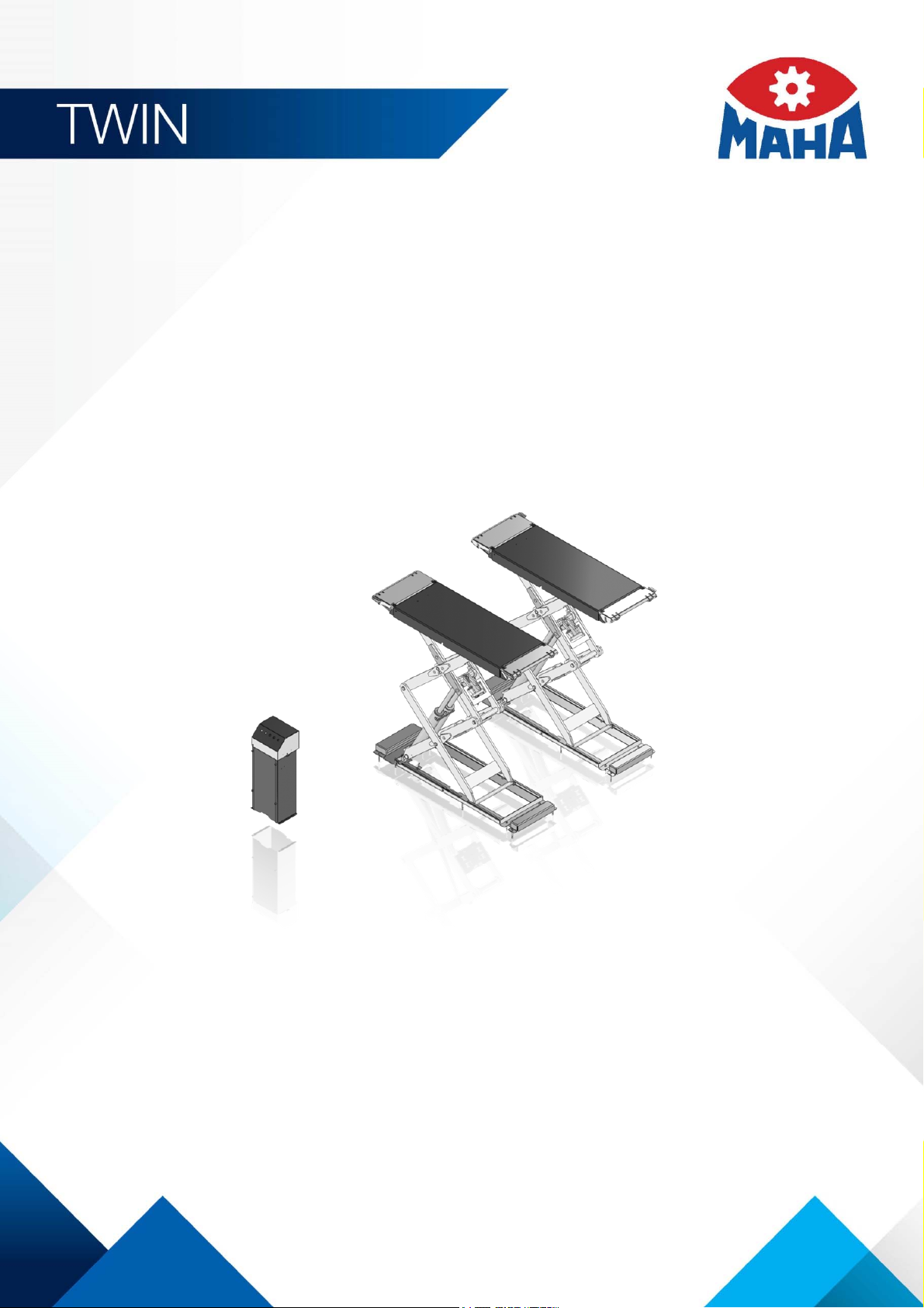
TWIN F III 3.0 | 4.0
Scissors Lift
Original Operating Instructions
BA082601-en
Pos: 1 /Technische Dokumentation/Hebetechnik/ TWIN/082601 TWIN F III 3.0 / 4.0/BA/I nhalt: 0826 Titelbil d @ 42\mod_1435573920051_0.d ocx @ 2262565 @ @ 1
Pos: 2 /-----Format-----/MANUELLER UMBRUCH Seitenumbruc h @ 0\mod_1134403577687_0.d ocx @ 1277 @ @ 1
Fehler! Verwenden Sie die Registerkarte 'Start', um Name dem Text zuzuweisen, der hier angezeigt werden soll.Fehler! Verwenden Sie
die Registerkarte 'Start', um Name dem Text zuzuweisen, der hier angezeigt werden soll.Fehler! Verwenden Sie die Registerkarte
'Start', um Name dem Text zuzuweisen, der hier angezeigt werden soll.
Page 2

2
Pos: 3 /-----For mat---- -/Inh altsv er zeic hn is - 3 Eb ene n @ 5\mod_ 116 88674 41046_ 75.do cx @ 729 20 @ @ 1
Contents
1 Safety ...................................................................................................................... 5
1.1 Introduction ......................................................................................................................................... 5
1.2 Symbols .............................................................................................................................................. 5
1.3 Intended Use ....................................................................................................................................... 5
1.4 Inappropriate Use ................................................................................................................................ 5
1.5 Safety Instructions for Commissioning ................................................................................................. 5
1.6 Safety Instructions for Operation ......................................................................................................... 5
1.7 Safety Instructions for Servicing ........................................................................................................... 6
1.8 Safety Instructions for Handling Hydraulic Fluid ................................................................................... 7
1.9 Additional Safety Instructions for Lifts with Transport Frame for Mobile Use ........................................ 7
1.10 What to Do in the Event of Defects or Malfunctions ............................................................................. 8
1.11 What to Do in the Event of an Accident ............................................................................................... 8
2 Description ............................................................................................................... 9
2.1 General Information ............................................................................................................................. 9
2.2 Specifications ...................................................................................................................................... 9
2.3 Sample Nameplate ............................................................................................................................ 14
3 Transport and Storage ........................................................................................... 15
4 Installation and Initial Operation .............................................................................. 15
5 Operation ............................................................................................................... 15
5.1 Requirements on the Operator .......................................................................................................... 15
5.2 Main Switch....................................................................................................................................... 15
5.3 Controls ............................................................................................................................................ 16
5.4 Driving onto the Lift ........................................................................................................................... 17
5.5 Using Support Blocks........................................................................................................................ 17
5.5.1 Stacking Two Blocks on Top of Each Other ...................................................................................... 20
5.6 Raising and Lowering ........................................................................................................................ 21
5.7 Operating the Ramp .......................................................................................................................... 21
5.8 Bleeding the Hydraulic System .......................................................................................................... 22
5.9 Manual Lowering ............................................................................................................................... 22
5.10 Equalizing the Support Plates ............................................................................................................ 23
5.11 Lift with Transport Frame for Mobile Use ........................................................................................... 24
6 Maintenance .......................................................................................................... 26
6.1 Maintenance Schedule ...................................................................................................................... 26
6.2 Annual Inspection .............................................................................................................................. 26
6.3 Refilling with Hydraulic Fluid .............................................................................................................. 27
6.4 Cleaning ............................................................................................................................................ 27
6.5 Spare Parts ....................................................................................................................................... 27
6.6 Troubleshooting ................................................................................................................................ 28
7 Service Lifetime ...................................................................................................... 29
BA082601-en
Page 3

3
8 Dismantling ............................................................................................................ 29
9 Disposal ................................................................................................................. 29
10 Contents of the Declaration of Conformity .............................................................. 29
11 Company Information ............................................................................................. 30
Pos: 4 /-----For mat---- -/MAN UELLER UMBRUCH S eitenumb ruch @ 0\m od_11 34403 5776 87_0.d ocx @ 1 277 @ @ 1
BA082601-en
Page 4

4
Pos: 5 /-----For mat---- -/MA NUEL LE R UM B RUCH Sei tenumbr uch @ 0\mod _113 44035 77687_ 0.d ocx @ 127 7 @ @ 1
BA082601-en
Page 5
5
1
Safety
1.1
Introduction
1.2
Symbols
1.3
Intended Use
1.4
Inappropriate Use
1.5
Safety Instructions for Commissioning
1.6
Safety Instructions for Operation
Pos: 6 /Technische D okumen tation/A lle Ger äte/ Überschr iften/ Übersc hriften 1/S/Üb erschri ft 1: Si cher heit @ 6\mod_1174482399906_75.docx @ 76962 @ 1 @ 1
Pos: 7 /Tec hnisc he Dok um entat ion /A lle Ger äte/ Üb erschr ifte n/Über sc hrifte n 1.1/ E/Üb ersc hrif t 1. 1: Einf ühru ng @ 6\mod_1174482219062_75.docx @ 76793 @ 2 @ 1
Pos: 8 /Technisc he Dokum enta tion/ All e Gerä te/In halte/ Sic herhe it/In halt : Ei nführ ung S icher hei t @ 6\ mod_1175609639562_75.docx @ 87528 @ @ 1
Thoroughly read this manual before operating the equipment and comply with the instructions.
Always display the manual in a conspicuous location.
Personal injury and property damage incurred due to non-compliance with these safety
Pos: 9 /Technische D okumen tation/A lle Ger äte/ Überschr iften/ Übersc hriften 1.1/S/ Überschr ift 1. 1: Sym bole @ 6\mod_1174482270875_75.docx @ 76865 @ 2 @ 1
Pos: 10 /Technische Dokume ntatio n/Alle Geräte/ Inhalte/ Sicher heit/In halt: Sy mbo le Sicher heit @ 14\mod_1239866667866_75.docx @ 361518 @ @ 1
instructions are not covered by the product liability regulations.
Important safety instructions. Failure to comply with instructions could result in personal injury or
property damage.
Important information.
Pos: 11 /Techn ische Dokume ntation/Al le Geräte/Übers chriften/ Überschrifte n 1.1/B/Über schrift 1.1: Bes timmungsg emäßer Gebrau ch @ 6\mod_ 1176 73402 2203_ 75.docx @ 8874 6 @ 2 @ 1
Pos: 12 /Technische Dokume ntatio n/Hebet echnik /00 HBZ Alle/I nhalte/I nhalt: Bestim mungs gemäßer Gebr auch HBZ @ 1 8\mod_1258013896259_75.docx @ 521484 @ @ 1
• This lift shall be used exclusively for the safe lifting of motor vehicles. Observe the rated load
capacity.
• The lift shall not be modified without the express written consent of the manufacturer. In case of
Pos: 13 /Technische Dokume ntatio n/Hebet echnik /08 Sc heren-H ebebü hnen/ 26 01 TWI N F III 3. 0 / 4.0/B A/Inha lt: 082 6 Best immu ngsgem äßer G ebrauc h Er gänzu ng @ 16\mod_1248965052382_75.docx @ 422766 @ @ 1
Pos: 14 /Technische Dokument ation/Alle Gerät e/Übersc hriften/Üb erschriften 1. 1/B/Übers chrift 1.1: Bestimm ungswid riger Gebrauc h @ 18\mod_1255530265027_75.docx @ 471571 @ 2 @ 1
Pos: 15 /Technische Dokume ntatio n/Hebet echnik /00 HBZ Alle/I nhalte/I nhalt: Best immungsw idrig er Gebr auch H BZ @ 19\mod_1267188702628_75.docx @ 794843 @ @ 1
non-compliance the declaration of conformity becomes void.
• The lift can be re-positioned on-site adhering to the mandatory ambient conditions.
Any use other than described is inappropriate, for example:
• Climbing on the lift supports
• Transporting persons on the lift supports
Pos: 16 /Technische Dokument ation/Alle Gerät e/Übersc hriften/Üb erschriften 1. 1/S/Übersc hrift 1. 1: Sic herhe itsv orschr ift en für die I nbe trieb nahm e @ 6\m od_1174482269156_75.docx @ 76838 @ 2 @ 1
• Usage as mobile work platform or for other lifting operations
Pos: 17 /Technische Dokume ntatio n/Papier korb/ Hebete chnik/In halt: S icherhe itsvor schrifte n für d ie Inbe triebn ahme H BZ @ 33\mod_1372072327331_75.docx @ 1795886 @ @ 1
• The lift shall be installed and commissioned by authorized service personnel only.
• The control desk shall not be installed in the danger zone of the lift.
• The standard lift version shall not be installed and commissioned in hazardous locations,
Pos: 18 /Technische Dokume ntatio n/Alle Geräte/ Übersc hriften/ Überschr iften 1.1/S/ Übersc hrift 1.1: Sic herheit svorschr iften f ür den Betri eb @ 6\m od_1174482268953_75.docx @ 76826 @ 2 @ 1
Pos: 19 /Technische Dokume ntatio n/Papier korb/ Hebete chnik/In halt: S icherhe itsvor schrifte n für d en Be trieb H BZ @ 23\mod_1298966659740_75.docx @ 981576 @ @ 1
outdoors, in moist rooms (e.g. car wash) or outside a temperature range of 0…40 °C.
• Observe the detailed operating instructions.
BA082601-en
Page 6

6
1.7
Safety Instructions for Servicing
• The lift may only be operated by trained personnel over 18 years of age.
• At initial operation, check the functionality of the safety devices.
• The control desk must be positioned in such a way that there is an unobstructed view to the
complete working area and the emergency stop can be accessed at all times.
• All structural parts of the equipment must be visually checked at regular intervals.
• Supply of suitable illuminating devices is the owner's/operator's responsibility.
• Do not allow anyone to stay in the danger zone when driving on or off the lift.
• If the operator is unable to see all parts of the danger zone, a trained second person must
monitor such areas.
• Center the vehicle on the lift when it is in fully lowered position.
• After positioning the vehicle on the lift secure it against roll-off.
• The load rating on the identification plate must not be exceeded.
• Keep the path of movement free of obstructions.
• Only use the vehicle manufacturer's recommended lift points.
• Do not use the lift for transporting persons.
• After raising the vehicle briefly, stop and check the lift supports for secure contact.
• Make sure the vehicle doors are closed during raising and lowering cycles.
• Make sure the parking brake is applied during raising and lowering cycles.
• Closely watch lift and vehicle during raising and lowering cycles.
• Do not allow anyone to stay in lift area during raising and lowering cycles.
• Observe the installation instructions for the axle lift.
• Use both hands when moving the axle lift.
• The axle lift must be in rest position during raising and lowering cycles.
• Do not allow anyone to climb on lift or inside raised vehicle.
• Comply with the applicable accident prevention regulations.
• Keep lift and vehicle free of tools and parts.
• Keep the lift and lift area clean.
• The main switch serves as emergency stop switch. In case of emergency turn it to "0".
• Protect the lift against unauthorized usage by padlocking the main switch.
• Protect all parts of the electrical equipment from humidity.
• Use caution with operating vehicle engines. Danger of poisoning!
• When removing heavy vehicle components, the centre of gravity can change. In such
circumstances appropriate action must be taken as required.
Pos: 20 /Technische Dokume ntatio n/Alle Geräte/ Übersc hriften/ Überschr iften 1.1/S/ Übersc hrift 1.1: Sic herheit svorschr iften f ür Serv icearbe iten @ 6\mod_1174482270640_75.docx @ 76850 @ 2 @ 1
• Residual risk: Tripping over runways of surface mounted lifts, tripping over tools.
Pos: 21 /Technische Dokume ntatio n/Papier korb/ Hebete chnik/In halt: S icherhe itsvor schrifte n für S ervicear beite n HBZ @ 23\mod_1298969580124_75.docx @ 981599 @ @ 1
• Service work must be done by authorized service technicians.
• Turn off and padlock the main switch before doing any repair, maintenance or setup work.
• The system must be unpressurized during maintenance work.
• Work on pulse generators or proximity switches must be done by authorized service
• Work on the electrical equipment must be done by service technicians or qualified electricians.
BA082601-en
technicians.
Page 7

7
1.8
Safety Instructions for Handling Hydraulic Fluid
1.9
Additional Safety Instructions for Lifts with Transport Frame for Mobile Use
• Ensure that ecologically harmful substances are disposed of in accordance with the appropriate
regulations.
• Do not use high pressure or steam jet cleaners. Do not use caustic cleaning agents.
• The lift's safety devices must be set by authorized service technicians.
Pos: 22 /Technische Dokument ation/Alle Gerät e/Übersc hriften/Üb erschriften 1. 1/S/Übersc hrift 1.1: Sicherhe itsvors chr ifte n fü r de n Um ga ng m it H yd rau lik öl @ 16\m od_1 24660 77295 23_7 5.docx @ 40128 4 @ 2 @ 1
Pos: 23 /Technische Dokume ntatio n/Alle Geräte/ Inhalte/ Sicher heit/In halt: Si cher heitsvorsc hrif ten für de n Umg ang m it Hyd rau liköl @ 16\m od_1246608009867_75.docx @ 401310 @ @ 1
• Do not replace or override the safety devices.
• Neutralize hydraulic fluid spills with binder.
• Remove contaminated clothing immediately.
• Inhalation: If symptoms persist, seek medical treatment.
• Skin contact: Wash skin immediately with soap and water. If skin irritation persists, seek
immediate medical advice.
• Eye contact: Rinse thoroughly with water and seek medical advice.
Pos: 24 /Tec hn isch e Do kum entat ion/Alle Gerät e/Übersc hriften/ Über schrifte n 1.1/ Z/Über schrift 1.1: Z usätzl iche Sic h.vor schrifte n für d ie Heb . mit G estel l für mob ile n E insa tz @ 16\ mod_1248965750447_75.docx @ 422801 @ 2 @ 1
Pos: 25 /Technische Dokume ntatio n/Hebet echnik /08 Sc heren-H ebeb ühn en/ 26 01 T WIN F II I 3. 0 / 4.0/ BA/ Inha lt: 082 6 Zus ätz lic he Sic herh eits vor sc hrift en TWIN F I II m obi l @ 16\mod_1248959423259_75.docx @ 422739 @ @ 1
• Ingestion: Do not induce vomiting. Seek immediate medical attention.
• The lift shall not be exposed to direct, external weather conditions (snow, rain, etc.).
• The lift shall not be erected, stored and commissioned in explosion- and fire-endangered
operating halls or in moisture-endangered rooms (wash halls). Above and beyond this, storage
is only allowed in enclosed rooms.
• The lift shall only be positioned and operated on an even surface.
• The maximum permissible inclination of the surface is 2 %.
• The underground surface shall be paved (cement, blacktop) and have sufficient solidity to bear
the load of the pressure forces that are created.
• The static friction between the underground and the lift contact surface shall be sufficient to
prevent sudden slipping. The lift shall not be used on snow-covered, icy underground surfaces.
The lift shall not be positioned and operated on surfaces which have been contaminated with
oil, gasoline or lubricants.
• It is forbidden to operate the lift on unpaved surfaces (e.g. grass, gravel etc.).
• Clean up the underground surface which may endanger the solid stance of the lift before
erection (e.g. gravel, stones).
• No objects (wooden boards etc.) shall be laid under the lift to compensate for uneven surfaces.
In this case, another, safer erection spot shall be chosen.
• The lift’s erection surface shall be cleared and kept clean of any objects sticking to it or any
other impurities (gravel, oil).
• Before lifting a vehicle, the lift stability shall be checked by the operating personnel.
• Vehicles shall only be lifted if the lift has been removed from the transport unit (forklift, brakable
dolly).
• An additional stroke length extension or lifting of the loaded lift is forbidden.
• The lift shall only be moved with suitable lifting and transport devices (ground conveyor). The
supports of the lifting and transport units shall fit to the supplied transport frame. Only forklifts
and dollies designed to meet valid machinery directives shall be used.
• The forks of the used lifting and transport unit (ground conveyor) shall be placed at least 1000
mm deep in the transport frame.
BA082601-en
Page 8

8
1.10
What to Do in the Event of Defects or Malfunctions
1.11
What to Do in the Event of an Accident
• The lift shall only be lifted using the transport frame. A different form of lifting is not allowed.
• The proper securing of the operating unit for transport shall be done as shown in the operating
• The operating unit shall only be transported in the shown position.
• During transport the side of the control cabinet with a label attached to it shall be in an up
• Immediately after transport the control cabinet shall be placed in an upward position. The lift
• Only one lift shall be transported at a time.
• The lift shall only be transported in its retracted position.
• The supplied retaining bracket shall be attached for the lift transport.
• No other objects shall be placed and/or transported on the lift during transport.
• The valid accident prevention and safety regulations of the respective transport device shall be
• Movable forks which are part of the transport unit shall be locked.
• Only lifting and transport units (e.g. manual dolly, forklift) with driving and parking brakes for
• The lifting and transport unit shall have a load capacity of at least 1000 kg.
• Using manual force the lift shall only be moved on an even surface (maximum inclination 2 %).
• Secure the lift against unintended movement using the parking brake if it remains on the lifting
• It is prohibited to move the lift on slippery (e.g. snow-covered) ground.
• When moving the lift or during normal operation never pinch or kink the hydraulic hoses.
• Never drive over the hoses with a vehicle, dolly etc.
• No objects shall be placed on the hoses.
Pos: 26 /Technische Dokument ation/Alle Gerät e/Übersc hriften/Üb erschriften 1. 1/V/Übersc hrift 1.1: Verhal ten im Störfall @ 6\mod_1178097008375_75.docx @ 90829 @ 2 @ 1
• Damaged or leaking hoses shall be replaced immediately.
manual.
position.
shall not be stored with the control cabinet in a horizontal position.
adhered to for the load security and transport.
controlled driving shall be used.
and transport unit after transporting.
The lift shall not be stored for a longer time period in a raised position on the transport unit.
Pos: 27 /Technische Dokume ntatio n/Hebet echnik /00 HBZ Alle/I nhalte/I nhalt: Verha lten im Störfal l HBZ @ 19\mod_1267177095494_75.docx @ 794570 @ @ 1
• In case of defects or malfunctions such as uncontrolled lift movement or deformation of the
superstructure, support or lower the lift immediately.
Pos: 28 /Techn ische Dok ument atio n/Al le Gerät e/Übers chrift en/Über schrifte n 1. 1/V/Über schrift 1.1: V erhal ten bei Unfällen @ 1 9\mod_ 126 71772 45337_ 75.do cx @ 794 600 @ 2 @ 1
Pos: 29 /Technische Dokume ntatio n/Alle Geräte/ Inhalte/ Sicher heit/In halt: V erhalt en be i Unfä llen @ 34\mod_1381128804654_75.docx @ 1837123 @ @ 1
• Turn off the main switch and secure it against unauthorized usage. Contact service.
• The injured person is to be removed from the danger area. Find out where dressing and
bandages are kept. Seek first-aid.
• Provide first-aid (stop bleeding, immobilise injured limbs), report the accident and seal off the
accident site.
• Immediately report any accident to your supervisor. Make sure a record is kept of every
occasion first-aid is provided, e.g. in an accident book.
Pos: 30 /-----For mat-----/MA N UELL ER UMBR UCH Se ite num br uch @ 0\mod_1134403577687_0.docx @ 1277 @ @ 1
BA082601-en
• Remain calm and answer any questions that may arise.
Page 9

9
2
Description
2.1
General Information
2.2
Specifications
TWIN F III 3.0
RDSF III 3.0
TWIN F III 4.0
RDSF III 4.0
Pos: 31 /Technische Dokument ation/Alle Gerät e/Übersc hriften/Üb erschriften 1/ B/Überschri ft 1: Beschreibun g @ 6\mod_1174482271453_75.docx @ 76889 @ 1 @ 1
Pos: 32 /Technische Dokume ntation/Al le Geräte/Übers chriften/ Überschrif ten 1.1/A/Übers chrift 1.1: All gemeines @ 6\mod_1182865005781_75.docx @ 97736 @ 2 @ 1
Pos: 33 /Technische Dokume ntatio n/Hebet echnik /08 Sc heren-Heb ebühn en/26 01 TW IN F III 3.0 / 4. 0/B A/I nha lt: 082 6 Bes chr eib ung All geme in es @ 22\m od_1290677137640_75.docx @ 946593 @ @ 1
The lift models TWIN F III 3.0 / 4.0 and RDSF III 3.0 / 4.0 are equipped with two support plates on
a scissors superstructure. The drive system consists of four hydraulic cylinders arranged in a
Pos: 34 /Technische Dokume ntatio n/Alle Geräte/ Übersc hriften/ Überschr iften 1.1/T/ Übers chrift 1.1: Tech nische Daten @ 7\mod_1184075526343_75.docx @ 99711 @ 2 @ 1
Pos: 35 /Technische Dokume ntatio n/Hebet echnik /08 Sc heren-H ebeb ühn en/ 26 01 T WIN F II I 3. 0 / 4.0/ BA/ Inha lt: 082 6 Te chn isch e Daten (T abel le) TWI N F III 3.0 / 4. 0_a lt @ 22\mod_1295877451297_75.docx @ 964706 @ @ 1
master-slave system. The lift is operated via a dead man's type control using pushbuttons.
Load capacity CE 3000 kg 4000 kg
Working pressure 270 bar 270 bar
Support plate width 550 mm 650 mm
Support plate length 1540…2100 mm 1540…2070 mm
Overall width 1910 mm 2100 mm
Lifting height max. 1900 mm 2000 mm
Lifting height min. 100 mm 135 mm
Supply voltage 3 x 400 V 1 x 230 V / 3 x 400 V
Shipping weight 800 kg 1145 kg
Power unit 2,2 kW
Fuse protection 16 A time-delay
Raising / Lowering time approx. 42 s
Reservoir capacity 8,4 l
Noise emission < 70 dB(A)
Pos: 36 /Technische Dokume ntatio n/Hebet echnik /00 HBZ Alle/I nhalte/I nfo!/In halt: Info - Be trieb sw armer Zusta nd / Tec hn. Ä nder unge n HBZ @ 6\m od_1177427042703_75.docx @ 90160 @ @ 1
The properties indicated apply to lifts running at operating temperature.
Specifications are subject to change without notice.
Pos: 37 /-----For ma t-----/MA N UEL LER UMB RUC H Se ite num br uch @ 0\m od_1134403577687_0.docx @ 1277 @ @ 1
BA082601-en
Page 10

10
TWIN F III 3.0 / RDSF III 3.0
Pos: 38 /Techn ische Dokume ntatio n/Hebet echnik/ 08 Scher en-H ebeb ühn en/ 26 01 T WIN F II I 3. 0 / 4. 0/B A/ Inha lt: 082 6 Bi ldun ter -/über sc hrift @ 20\mod_1267190588784_75.docx @ 794967 @ @ 1
Pos: 39 /Tec hn isch e Do kument ation/H ebetech nik/0 8 S chere n-Heb ebü hn en/2 601 TWI N F III 3.0 / 4. 0/B A/I nhalt : 08 26 Tec hnis che Da ten ( Bild er) @ 14\m od_12 39796 7523 44_0.d ocx @ 3 61438 @ @ 1
BA082601-en
Page 11

11
Pos: 40 /-----For ma t-----/MA N UEL LER UMB RUC H Se ite num br uch @ 0\m od_1134403577687_0.docx @ 1277 @ @ 1
BA082601-en
Page 12

12
TWIN F III 3.0 / RDSF III 3.0 with Transport Frame for Mobile Use
Pos: 41 /Technische Dokume ntatio n/Hebet echnik /08 Sc heren-H ebeb ühn en/ 26 01 T WIN F II I 3. 0 / 4.0/ BA/ Inha lt: 082 6 Bi ldun ter -/übe rsc hr ift m it M ob ilges te ll @ 1 6\mod_1249034947940_75.docx @ 423490 @ @ 1
Pos: 42 /-----For ma t-----/MA NUEL LER UM BRUC H Zeile nscha ltun g @ 7\mod_ 1195 1389 65731_ 0.doc x @ 13217 7 @ @ 1
Pos: 43 /Technische Dokume ntatio n/Hebet echnik /08 Sc heren-H ebeb ühn en/ 26 01 T WIN F II I 3. 0 / 4.0/ BA/ Inha lt: 082 6 Te chn isch e Daten Mob il ges tell ( Bi lder ) @ 16\m od_1249035206637_0.docx @ 423717 @ @ 1
Pos: 44 /-----For ma t-----/MA N UEL LER UMB RUC H Se ite num br uch @ 0\m od_1134403577687_0.docx @ 1277 @ @ 1
BA082601-en
Page 13

13
TWIN F III 4.0 / RDSF III 4.0
Pos: 45 /Technische Dokume ntatio n/Hebet echnik /08 Sc heren-H ebeb ühn en/ 26 01 T WIN F II I 3. 0 / 4.0/ BA/ Inha lt: 082 6 B ildu nter -/überschrift TWIN F III 4.0 @ 20\mod_1267190712415_75.docx @ 794998 @ @ 1
Pos: 46 /Technische Dokume ntatio n/Hebet echnik /08 Sc heren-H ebeb ühn en/ 26 01 T WIN F II I 3. 0 / 4.0/ BA/ Inha lt: 082 6 Te chn isch e Daten (Bilder) TWIN F III 4.0 @ 20\mod_1267190159706_0.docx @ 795029 @ @ 1
BA082601-en
Page 14

14
2.3
Sample Nameplate
Pos: 47 /Technische Dokume ntatio n/Alle Geräte/ Überschrift en/Überschr iften 1.1/T/ Überschri ft 1.1: Typensch ild-Must er @ 11\m od_12 27622 2060 96_7 5.docx @ 27557 4 @ 2 @ 1
Pos: 48 /Technische Dokume ntatio n/Hebet echnik /08 Sc heren-Heb ebühn en/00 01 Scher en-Heb ebühne n Alle/ Inhal te/Inhal t: Typenschild-M uster M AHA S chere n-HBZ @ 2 4\mod_1305811444728_75.docx @ 1010345 @ @ 1
SCISSORS LIFT
Ser. No. / Date of Production: ***
Project: ***
Model and Version: ***
Supply Voltage: ***
Frequency: ***
Rated Current: ***
Fuse Protection: ***
Load Capacity: ***
Pos: 49 /-----For ma t-----/MA N UEL LER UMB RUC H Se ite num br uch @ 0\m od_1134403577687_0.docx @ 1277 @ @ 1
BA082601-en
Page 15

15
3
Transport and Storage
4
Installation and Initial Operation
5
Operation
5.1
Requirements on the Operator
5.2
Main Switch
Pos: 50 /Technische Dokument ation/Alle Gerät e/Übersc hriften/Üb erschriften 1/ T/Überschri ft 1: Tr ans por t und La ger un g @ 2 0\mod_1268732488860_75.docx @ 826153 @ 1 @ 1
Pos: 51 /Technische Dokument ation/Alle Gerät e/Inhalte/ Inhalt: Tra nsport und Lageru ng @ 20\mod_1268726449998_75.docx @ 825913 @ @ 1
Check package to ensure it is complete, in accordance with the order confirmation. Report any
transport damage to the carrier immediately.
During loading, unloading and transport always use suitable lifting equipment, material handling
equipment (e.g. cranes, forklifts, etc.) and the right load handling attachments and slings. Always
ensure that the parts to be transported are suspended or loaded properly so that they cannot fall,
taking into account size, weight and the centre of gravity.
Store the packages in a covered area, protected from direct sunlight, at a low humidity and with
temperatures between 0...40 °C (32…104 °F). Do not stack packages.
When unpacking, take care to avoid any possibility of injury or damage. Keep at a safe distance
Pos: 52 /Technische Dokume ntatio n/Alle Geräte/ Übersc hriften/ Überschr iften 1/M/Üb ersc hrift 1: M ontag e und E rstinbe triebn ahme @ 18\mod_1255417443299_75.docx @ 463797 @ 1 @ 1
Pos: 53 /Techn ische Dokume ntatio n/Hebet echnik/ 00 HBZ Alle/In halte/In halt: Montag e und E rstinb etriebn ahme H BZ @ 19\mod_1266324736624_75.docx @ 741895 @ @ 1
when opening the package strapping, do not allow any parts to fall out.
Installation and commissioning of the equipment must be carried out by specially trained
personnel, authorised for the task. Specialist personnel includes authorised, trained skilled staff
Pos: 54 /Technische Dokument ation/Alle Gerät e/Übersc hriften/Üb erschriften 1/ B/Überschri ft 1: Bedienu ng @ 6\mod_1174482271218_75.docx @ 76877 @ 1 @ 1
from the manufacturer, the dealer and the relevant service partners.
Pos: 55 /Technische Dokument ation/Papier korb/Über schriften/ Überschrif t 1.1: Anforderun gen an den Bediener @ 1 8\mod_1255531954990_75.docx @ 471737 @ 2 @ 1
Pos: 56 /Tec hnische Dokume ntation/ Alle Geräte/Inh alte/War nung!/Inha lt: Warnung - Anf orderun gen an d en Bediener @ 19\m od_1267188989019_75.docx @ 794905 @ @ 1
All persons employed in the operation, maintenance, installation, removal and disposal of the plant
must
• be at least 18 years old,
• be trained and instructed in writing,
• have read and understood this manual
• be on record as having been intructed in safety guidelines.
Pos: 57 /Technische Dokument ation/Alle Gerät e/Übersc hriften/Üb erschriften 1. 1/H/Überschr ift 1.1: Haup tschalter @ 6\mod _117 75928 58312_ 75.d ocx @ 90 635 @ 2 @ 1
Pos: 58 /Technische Dokume ntatio n/Hebet echnik /00 HBZ Alle/I nhalte/I nhalt: Haup tschalter mit N ot-Aus- Funk tion H BZ @ 22\mod_1295874475528_75.docx @ 964591 @ @ 1
The main switch is used as emergency switch. In case of emergency turn it to position 0.
• Main switch in position 0: Power supply is interrupted
• Main switch in position 1: Lift is ready for operation
• When in position 0, the main switch can be protected against tampering
by means of a padlock.
Pos: 59 /-----For ma t-----/MA N UEL LER UM BRUC H Se ite num br uch @ 0\m od_1134403577687_0.docx @ 1277 @ @ 1
BA082601-en
Page 16

16
5.3
Controls
A
B
C
D
E
Pos: 60 /Technische Dokument ation/Alle Gerät e/Übersc hriften/Üb erschriften 1. 1/B/Übers chrift 1.1: Bedien elemente @ 13\m od_12 37975 0991 77_7 5.docx @ 35900 8 @ 2 @ 1
Pos: 61 /Technische Dokume ntatio n/Hebet echnik /08 Sc heren-H ebeb ühn en/ 26 01 T WIN F II I 3. 0 / 4.0/ BA/ Inha lt: 082 6 B edie nele me nte ( Bi ld) @ 22\ mod_1295874833033_0.docx @ 964618 @ @ 1
A
Pos: 62 /Technische Dokume ntatio n/Hebet echnik /08 Sc heren-H ebeb ühn en/ 26 01 T WIN F II I 3. 0 / 4.0/ BA/ Inha lt: 082 6 B edie nele me nte ( Tab elle ) @ 22\mod_1295875588398_75.docx @ 964648 @ @ 1
Main Switch
Button CE-STOP
B
C
D
Audible Indicator
Key Switch
E
Buttons RAISE/LOWER
Pos: 63 /Technische Dokume ntatio n/Hebet echnik /08 Sc heren-H ebeb ühn en/ 26 01 T WIN F II I 3. 0 / 4.0/ BA/ Inha lt: 082 6 B edie nele me nte ( Tex t) @ 22\mod_1295875826646_75.docx @ 964676 @ @ 1
• Use the main switch (A) to switch the lift on and off.
• When button RAISE or LOWER (C) is pushed, the lift moves until the button is released or the
limit stop is reached.
• When fully lowering the lift, the support plates stop automatically at a height of 300 mm above
bottom position. Release the LOWER button and push the CE STOP button (D).
The remaining lift travel is accompanied by an audible indicator (B).
• The key switch (E) is used for manually levelling the support plates. See section "Equalizing the
Pos: 64 /-----For ma t-----/MA N UEL LER UMB RUC H Se ite num br uch @ 0\m od_1134403577687_0.docx @ 1277 @ @ 1
Support Plates".
BA082601-en
Page 17

17
5.4
Driving onto the Lift
5.5
Using Support Blocks
Pos: 65 /Technische Dokume ntatio n/Alle Geräte/ Übersc hriften/ Überschr iften 1. 1/B/Üb erschr ift 1. 1: Befahr en @ 6\m od_11 80607 4977 03_7 5.docx @ 94502 @ 2 @ 1
Pos: 66 /Technische Dokume ntatio n/Hebet echnik /08 Sc heren-H ebeb ühn en/ 26 01 T WIN F II I 3. 0 / 4.0/ BA/ Inha lt: 082 6 W arnu ng - Befahren @ 1 8\mod_ 1 257327463358_75.docx @ 513053 @ @ 1
1 Make sure the ramps are locked before
driving onto the lift!
3 Observe correct approach direction! Do not
engage the vehicle perpendicular to lift!
Pos: 67 /Technische Dokume ntatio n/Alle Geräte/ Übersc hriften/ Überschr iften 1.1/A/ Übersc hrift 1.1: Auf nahmek lötze v erwe nden @ 44\mod_1459263520420_75.docx @ 2427031 @ 2 @ 1
Pos: 68.1 /Technisch e Dokum entat ion/Heb etech nik/00 H BZ Al le/Inhal te/Inha lt: Aufna hmek lötze H BZ - V orgehe nswe ise (Tex t) @ 44\mod_1461682559816_75.docx @ 2437527 @ @ 1
1 The support blocks are approved for usage on lifts with a rated load capacity of
3,500 kgs.
2 Always use four original MAHA support blocks of identical size and shape.
3 Do not use support blocks with cracks, broken-off pieces or other damage.
4 Check that all support blocks and rubber pads are free of oil, grease, dirt or
debris.
5 Place the support blocks under the vehicle manufacturer‘s recommended lift
points.
6 Note correct positioning of the support blocks.
2 Approach and exit the lift very slowly! The
chassis of low vehicles may hit the floor.
7 Raise the vehicle until the tyres clear the floor. Stop and recheck the lift
Pos: 68.2 /----- Form at-----/ MAN UE LLE R UM BR UCH Seit en umb ruch @ 0\mod_1134403577687_0.docx @ 1277 @ @ 1
supports for secure contact with the vehicle body.
BA082601-en
Page 18

18
A C B B A
C
Pos: 68.3 /Technisch e Dokum entat ion/Heb etech nik/00 H BZ Al le/Inhal te/Inha lt: Aufna hmek lötze H BZ - Z ulässi ger Berei ch (Tex t) @ 44\mod_1459257598516_75.docx @ 2426593 @ 3 @ 1
The support block must be placed fully on the surface without extending byond
the edges.
A Extension B Support surface; available are:
C Support block
Pos: 68.4 /Technisch e Dokum entat ion/Heb etech nik/00 H BZ Al le/Inhal te/Inha lt: Aufna hmek lötze H BZ - Z ulässi ger Berei ch (Bi lder) @ 44\mod_1459255428157_0.docx @ 2425779 @ @ 1
– Granulate coating
– Granulate foil
– Rubber plate
Pos: 68.5 /----- Form at-----/ MAN UE LLE R UM BR UCH Seit en umb ruch @ 0\mod_1134403577687_0.docx @ 1277 @ @ 1
BA082601-en
Page 19

19
a
a
b
Pos: 68.6 /Technisch e Dokum entat ion/Heb etech nik/00 H BZ Al le/Inhal te/Inha lt: Aufna hmek lötze H BZ - Diagonal (Text) @ 44\mod_1459259263636_75.docx @ 2426639 @ 3 @ 1
Diagonal positioning is permissible only with granulate coated surfaces (a). If
Pos: 68.7 /Technisch e Dokum entat ion/Heb etech nik/00 H BZ Al le/Inhal te/Inha lt: Aufna hmek lötze H BZ - D iag onal (B ild er) @ 4 4\mod _145 92566 09357_ 0.d ocx @ 242 5825 @ @ 1
knobbly pads are used, these must mesh with the support blocks (b).
Pos: 68.8 /----- Form at-----/ MAN UE LLE R UM BR UCH Seit en umb ruch @ 0\mod_1134403577687_0.docx @ 1277 @ @ 1
BA082601-en
Page 20

20
5.5.1
Stacking Two Blocks on Top of Each Other
Pos: 68.9 /Technisch e Dokum entat ion/Heb etech nik/00 H BZ Al le/Inhal te/Inha lt: Aufna hmek lötze H BZ - Sta pe ln (T ext) @ 4 4\mod_1459262938946_75.docx @ 2426985 @ 3 @ 1
Only the “DUO“ hard rubber blocks (VZ 975074) and the ductile plastic blocks (VZ
970045) may be stacked on top of each other, but not more than two blocks per
Pos: 68.10 /Te chnis che D okum enta tion/H ebe techn ik/ 00 HBZ All e/Inha lte/ Inha lt: A ufnahm ekl ötze H BZ - Stap eln (B ilder ) @ 44\mod _1459252038981_0.docx @ 2424947 @ @ 1
lifting point.
Pos: 69 /-----For ma t-----/MA N UEL LER UMB RUC H Se ite num br uch @ 0\m od_1134403577687_0.docx @ 1277 @ @ 1
BA082601-en
Page 21

21
5.6
Raising and Lowering
5.7
Operating the Ramp
A
A
A
Pos: 70 /Technische Dokume ntatio n/Alle Geräte/ Übersc hriften/ Überschr iften 1.1/H /Überschr ift 1 .1: Heb en u nd Senken @ 6\mod_1178521944593_75.docx @ 91237 @ 2 @ 1
Pos: 71 /Technische Dokume ntatio n/Hebet echnik /08 Sc heren-H ebebü hnen/ 26 01 TWI N F III 3. 0 / 4.0/B A/Inha lt: 082 6 Hebe n und Senk en @ 2 0\mod_1267193381973_75.docx @ 795157 @ @ 1
1 Turn the main switch to position 1.
Lift is ready for operation.
2 Push and hold the RAISE button until the lift reaches the desired height.
Lift stops once button is released or upper limit stop is reached.
3 Push and hold the LOWER button until the lift reaches the desired height.
Lift stops once button is released or CE-Stop is reached.
4 To lower the lift completely, release the LOWER button and push the CE-STOP button.
The remaining lift travel to the lower limit stop is accompanied by an audible indicator.
Risk of injury!
Before lowering the lift to bottom position, verify that there are no persons or obstructions in the
danger area.
Pos: 72 /Tec hn isch e Do kumentatio n/Alle Geräte/ Überschrift en/Überschr iften 1.1/B/ Überschrif t 1.1: Bedienun g der Rampe @ 14\mod_ 123 97885 39802 _75.d ocx @ 361 303 @ 2 @ 1
Pos: 73 /Technische Dokume ntatio n/Hebet echnik /08 Sc heren-Hebebühnen/2601 TWIN F III 3.0 / 4. 0/B A/ Inha lt: 082 6 Be die nung der Ra mpe (Bi ld) @ 2 2\mod_1290675325881_0.docx @ 946491 @ @ 1
Pos: 74 /Technische Dokume ntatio n/Hebet echnik /08 Sc heren-Hebeb ühn en/ 26 01 T WIN F II I 3. 0 / 4.0/ BA/ Inha lt: 08 26 B edie nun g de r R amp e (Te xt) @ 2 2\mod_1295881364527_75.docx @ 964741 @ @ 1
Pos: 75 /-----For ma t-----/MA N UEL LER UMB RUC H Se ite num br uch @ 0\mod_1134403577687_0.docx @ 1277 @ @ 1
Lift the ramp and reposition it using the lateral handle (A).
BA082601-en
Page 22

22
5.8
Bleeding the Hydraulic System
5.9
Manual Lowering
2 3 1
Pos: 76 /Technische Dokume ntatio n/Alle Geräte/ Übersc hriften/ Überschr iften 1.1/H /Überschr ift 1 .1: Hy drauliksy stem e ntlüf ten @ 6\m od_1180531444046_75.docx @ 94390 @ 2 @ 1
Pos: 77 /Technische Dokume ntatio n/Hebet echnik /00 HBZ Alle/I nhalte/I nfo!/In halt: Info - E ntlü ftun g durc h Serv ice @ 1 4\mod_1239951513310_75.docx @ 361778 @ @ 1
Bleeding of hydraulic system is done by authorized service technicians.
Pos: 78 /Tec hn ische Dokum entation/ Alle Geräte/Üb erschriften/ Überschri ften 1.1/M/ Überschrift 1.1: Manuelles Abse nken @ 6\mod_1178113285703_75.docx @ 90869 @ 2 @ 1
Pos: 79 /Technische Dokume ntatio n/Hebet echnik /00 HBZ Alle/I nhalte/ Warnu ng!/Inha lt: Warnung - Manuelles Absen ken n ur durch gesch ultes Perso nal @ 6\mod _1180 9622 17687_ 75.d ocx @ 9521 7 @ @ 1
Authorized personnel only! Do not restart the lift before the error has been remedied.
Pos: 80 /Technische Dokume ntatio n/Hebet echnik /08 Sc heren-H ebeb ühn en/ 26 01 T WIN F II I 3. 0 / 4.0/ BA/ Inha lt: 082 6 Ma nue lles Abs enk en ( Bi lder ) @ 14\m od_1239954545012_0.docx @ 361862 @ @ 1
Pos: 81 /Technische Dokume ntatio n/Hebet echnik /08 Sc heren-H ebeb ühn en/ 26 01 T WIN F II I 3. 0 / 4.0/ BA/ Inha lt: 082 6 Ma nue lles Abs enk en ( Tex t) @ 14\ mod_1239955585918_75.docx @ 361888 @ @ 1
1 Disable solenoid valve Y1 by closing it.
2 Push and hold solenoid valve Y3.
3 Push and hold solenoid valve Y2.
4 While lowering check the support plates for synchronized movement.
Pos: 82 /-----For ma t-----/MA N UEL LER UMB RUC H Se ite num br uch @ 0\m od_1134403577687_0.docx @ 1277 @ @ 1
BA082601-en
5 When the lift is in bottom position, release Y2 and Y3 and enable Y1 by opening it.
Page 23

23
5.10
Equalizing the Support Plates
Pos: 83 /Technische Dokument ation/Alle Gerät e/Übersc hriften/Üb erschriften 1. 1/A/Übersc hrift 1.1: Aufnahm eplatten nive llieren @ 16\ mod_1249031313151_75.docx @ 423395 @ 2 @ 1
Pos: 84 /Technische Dokume ntatio n/Hebet echnik /08 Sc heren-H ebeb ühn en/ 26 01 T WIN F II I 3. 0 / 4.0/ BA/ Inha lt: 082 6 A ufn ahmep lat te n niv ell iere n 2 (Bild ) @ 2 2\mod_1295872449018_0.docx @ 9 643 59 @ @ 1
Pos: 85 /Technische Dokume ntatio n/Hebet echnik /08 Sc heren-H ebeb ühn en/ 26 01 T WIN F II I 3. 0 / 4.0/ BA/ Inha lt: 082 6 A ufn ahmep lat te n niv ell iere n 2 (Tex t) @ 2 2\mod_1295872770924_75.docx @ 964519 @ @ 1
Requirements:
• Lift in unloaded condition.
• Lifting height not above 300 mm (CE Stop).
1 Actuate the key switch.
2 Use button RAISE or LOWER to move the slave side in single operation.
3 When both sides are level with each other, turn off the key switch.
Lift is in normal operation mode.
During normal operation, keep the key in a safe place to protect it against unauthorized usage.
Pos: 86 /-----For ma t-----/MA N UEL LER UMB RUC H Se ite num br uch @ 0\m od_1134403577687_0.docx @ 1277 @ @ 1
BA082601-en
Page 24

24
5.11
Lift with Transport Frame for Mobile Use
Transport Preparation
C D E
Pos: 87 /Tec hn isch e Do kument ation/Al le Gerät e/Über schrift en/Üb erschri ften 1. 1/H/Über schr ift 1.1: Hebebü hne mi t Geste ll für m obile n Einsa tz @ 16\mod_1248966031988_75.docx @ 422821 @ 2 @ 1
Pos: 88 /Technische Dokume ntatio n/Hebet echnik /08 Scheren-Hebebühn en/ 26 01 T WIN F II I 3. 0 / 4.0/ BA/ Inha lt: 082 6 W arnu ng - S icherh eit Mob ilges tell b eachten @ 16\mod_1249035916701_75.docx @ 423744 @ @ 1
Pay close attention to section "Safety / Additional Safety Instructions for Lifts with Transport Frame
for Mobile Use"!
Pos: 89 /Technische Dokume ntatio n/Hebet echnik /08 Sc heren-H ebeb ühn en/ 26 01 T WIN F II I 3. 0 / 4.0/ BA/ Inha lt: 082 6 Mob il ges tell ( B ilder ) @ 16\m od_1248957560864_0.docx @ 422713 @ @ 1
Pos: 90 /Technische Dokume ntatio n/Hebet echnik /08 Sc heren-H ebeb ühn en/ 26 01 T WIN F II I 3. 0 / 4.0/ BA/ Inha lt: 082 6 Mob il ges tell ( Tex t) @ 16\ mod_1249028589143_75.docx @ 423097 @ @ 1
1 Attach brackets (A) and (B) to the lift.
2 Securely connect brackets with screws (C) and nuts (D).
3 Place the operating unit on the mobile transport frame. Make sure that the label is showing on
top. Attach to transport frame with locking screws (E).
4 Drive the lifting forks of the ground conveyer into the openings (F). The lifting forks must engage
Pos: 91 /-----For ma t-----/MA N UEL LER UMB RUC H Se ite numb ruch @ 0\m od_1134403577687_0.docx @ 1277 @ @ 1
BA082601-en
the transport frame with a depth of at least 1000 mm!
Page 25

25
Labels
Pos: 92 /Technische Dokume ntatio n/Hebet echnik /08 Sc heren-H ebeb ühn en/ 26 01 T WIN F II I 3. 0 / 4.0/ BA/ Inha lt: 082 6 Mob il ges tell Auf kleb er ( Tex t) @ 16\m od_1249029324524_75.docx @ 423204 @ @ 1
This label is located on the front and rear edge
of the transport frame.
(Warning symbol in accordance with
BGV A 8 W14, DIN 4844-2 D-W014).
Explanation: Warning about tripping danger
Pos: 93 /Technische Dokume ntatio n/Hebet echnik /08 Sc heren-H ebeb ühn en/ 26 01 T WIN F II I 3. 0 / 4.0/ BA/ Inha lt: 082 6 Mob il ges tell Auf kleb er ( B ilder ) @ 16\mod_1249027419252_0.docx @ 423070 @ @ 1
Pos: 94 /-----For ma t-----/MA N UEL LER UMB RUC H Se ite num br uch @ 0\m od_1134403577687_0.docx @ 1277 @ @ 1
This label is located on the side part of the
operating unit. It must always be showing on top
during transport!
BA082601-en
Page 26

26
6
Maintenance
6.1
Maintenance Schedule
Interval
Maintenance items
Procedure
6.2
Annual Inspection
12 (twelve) months
Pos: 95 /Technische Dokume ntatio n/Papier korb/ Übersc hriften/ Überschr ift 1: Inst andh altu ng @ 1 1\mod _12 3131 87366 29_75.d ocx @ 28 9550 @ 1 @ 1
Pos: 96 /Technische Dokume ntatio n/Alle Geräte/ Inhalte/ Warnu ng!/In halt: W arnung - Haup tscha lter aus bei I nsta ndhal tung @ 1 4\mod_1240239070975_75.docx @ 362949 @ @ 1
Danger! Electric shock hazard!
Before doing any maintenance work, turn off the main switch and protect it against tampering.
Pos: 97 /Technische Dokume ntatio n/Alle Geräte/ Übersc hriften/ Überschr iften 1.1/I /Überschr ift 1. 1: Ins tandhal tungsp lan @ 11\mod_1231318919401_75.docx @ 289622 @ 2 @ 1
Pos: 98 /Technische Dokume ntatio n/Hebet echnik /08 Sc heren-Heb ebühn en/00 01 Scher en-Heb ebühne n Alle/ Inhal te/Inhal t: Inst andhal tungsplan Scher en-HB Z @ 24\mod_1305897905902_75.docx @ 1010994 @ @ 1
3 months
6 months Hydraulic fluid
12 months General inspection Check all components for damage.
6 years Pressure hoses Replace pressure hoses.
Pos: 99 /Technische Dokument ation/Papier korb/Über schriften/ Überschrif t 1.1: Jährliche Überp rüfung @ 6\mod _11 74482 24571 8_75.d ocx @ 76 817 @ 2 @ 1
Hydraulic system
Slider tracks and sliding
surfaces of extensions
Check fluid level, top up if necessary.
Check hydraulic system for leakage.
Check power unit for unusual noise during
operation, check fastening screws for tight fit.
Grease slightly.
Check fluid for soiling and aging, replace if
necessary.
Pos: 100 /Tech nische Dok umen tati on/A lle G eräte/ Inha lte/ Info!/I nha lt: Inf o - Jährli che Über prüfung @ 1 4\mod_1242051457491_75.docx @ 373548 @ @ 1
• The maintenance interval prescribed by the manufacturer is
This maintenance interval refers to normal workshop usage. If the equipment is used more
frequently or under severe operating conditions (e.g. outdoors), the interval must be reduced
accordingly.
• Maintenance work shall be done only by authorized and trained service technicians provided by
the manufacturer, licensed dealers or service partners.
• In case of non-compliance the manufacturer's warranty becomes void.
Pos: 101 /Tech nische Dok umen tati on/Heb ete chnik/ 00 H BZ A lle/ Inhal te/Inf o!/ Inhal t: I nfo - DGUV Regel 100-500 / DGUV Grundsatz 308-003_12pt @ 47\mod_1483611185270_75.docx @ 2804763 @ @ 1
Pos: 102 /-----F orm at-----/M ANUELLE R UMBR UCH Seite numbru ch @ 0\mod_1134403577687_0.docx @ 1277 @ @ 1
.
BA082601-en
Page 27

27
6.3
Refilling with Hydraulic Fluid
6.4
Cleaning
6.5
Spare Parts
Pos: 103 /Technische Dokum entati on/Alle G eräte/ Übers chrifte n/Über schrifte n 1.1/H/ Über schrift 1.1: Hyd rauli köl nac hfüllen @ 6\ mod_1180614998015_75.docx @ 94590 @ 2 @ 1
Pos: 104 /Technische Dokum entati on/Hebe technik/ 08 Sch eren-He b ebüh ne n/260 1 TW IN F II I 3. 0 / 4. 0/BA/ Inh alt: 08 26 Ö lsta nd prü fen ( Bild ) @ 14\mod_ 12 397 880 174 57_0.d oc x @ 361 277 @ @ 1
Pos: 105 /Te ch nisc he D ok umenta tion/Heb ete chnik/Arc hiv/08 Scher en-Hebeb üh nen/ 2701 M PL 3.5/BA /In halt: 08 27 Öls tand prüfen (T ext) @ 12\mod_1232976039115_75.docx @ 323186 @ @ 1
1 Check hydraulic fluid level every 3 months with a completely lowered lift.
Pos: 106 /Tech nische Dok umen tati on/Heb ete chnik/ 00 H BZ A lle/ Inhal te/Inf o!/ Inhal t: I nfo - Ta usch v on Öl u nd Dr ucksch läuchen @ 14\ mod_1239952209207_75.docx @ 361832 @ @ 1
2 Add missing fluid via the filler inlet. Make sure hydraulic fluid meets HLPD 32 specification.
• Replace the hydraulic fluid periodically, depending on aging, soiling and water absorption.
• When topping up, use fluid with the same specification only.
• If the lift is operated permanently at an ambient temperature of < 15 °C, use hydraulic fluid with
a lower viscosity.
• The pressure hoses should be replaced as required, but after six years at the latest.
Pos: 107 /Technische Dokum entati on/Alle G eräte/ Übers chrifte n/Über schrifte n 1.1/ R/Übersc hrif t 1.1: Reinigun g @ 6\ mod_ 11786 17677 265_ 75.do cx @ 915 86 @ 2 @ 1
Pos: 108 /Te ch nisc he D ok umen tati on/P ap ierk orb /alt/ In halt : R eini gun g HBZ @ 7\mod_1197289850229_75.docx @ 137426 @ @ 1
Pos: 109 /Te ch nisc he D ok umen tati on/A ll e Ger äte/Inhalte/ Warnung!/I nhalt: Warnun g - Beschädi gungsgef ahr/Re inigung @ 14\ mod_1239952020489_75.docx @ 361805 @ @ 1
Periodically wash off aggressive substances and treat the lift with oil or wax spray.
Risk of damage!
Do not use high pressure or steam jet cleaners. Do not use caustic cleaning agents.
Pos: 110 /Te ch nisc he D okumen tation/A lle G eräte/ Überschr iften/Üb erschr iften 1 .1/E/ Überschr ift 1. 1: Ersa tztei le @ 18\m od_1255596847002_75.docx @ 474414 @ 2 @ 1
Pos: 111 /Technische Dokum entati on/Alle G eräte/I nha lte/Inha lt: Ersatz teile - Alle G eräte @ 20\m od_ 126 71892 161 13_7 5.docx @ 79493 6 @ @ 1
To ensure safe and reliable operation, only use original spare parts supplied by the equipment
Pos: 112 /-----F orm at-----/M ANUELLE R UMBR UCH Seite numbru ch @ 0\mod_1134403577687_0.docx @ 1277 @ @ 1
manufacturer.
BA082601-en
Page 28

28
6.6
Troubleshooting
Error
Diagnosis
Remedy
Pos: 113 /Te chnische Dok umenta tion/All e Ger äte/Über schrifte n/Üb erschrif ten 1.1/ F/Übers chrift 1.1: F ehlerb ehebun g @ 8\m od_1 20671 46467 48_7 5.docx @ 17962 0 @ 2 @ 1
Pos: 114 /Technische Dokum entati on/Hebe technik/ Archiv/ 08 Sch eren-H ebeb ühnen/ 25 01 TWIN F II 3.0/BA/Inhalt: 0825 Fehlerbehebung TWIN F II/III @ 7\mod_1183639766437_75.docx @ 99102 @ @ 1
Main switch turned off. Turn on main switch.
Lift does not run.
Lift does not raise.
Lift capacity insufficient.
Lift does not lower.
Lift raises and lowers considerably faster than usually.
Support plates lower without
control button being pressed.
Power failure.
Check for cause of power
failure.
Power cord interrupted. Replace defective cord.
Fuses defective. Replace fuses.
Motor rotation reverse.
Interchange two phases at
main switch.
Low fluid level. Refill fluid reservoir.
Button RAISE defective.
Check button and line, replace
if necessary.
Pump intake filter dirty. Check and clean filter.
Pressure valve maladjusted.
Contact service.
Pump defective.
LOWER solenoid valve
defective.
Contact service.
LOWER button defective.
RAISE and/or LOWER solenoid
valve defective.
LOWER solenoid valve does
not close completely.
Leakage in at least two
hydraulic lines.
Contact service.
Contact service.
Check connections for tight fit
and hoses for damage, replace
if necessary.
Lift shows jerky movements.
Pos: 115 /-----F ormat -----/M ANUELLE R UMBR UCH Seitenum bruch @ 0\ mod_1134403577687_0.docx @ 1277 @ @ 1
BA082601-en
Pressure valves maladjusted.
Contact service.
Air in hydraulic system.
Page 29

29
7
Service Lifetime
8
Dismantling
9
Disposal
10
Contents of the Declaration of Conformity
MAHA Maschinenbau Haldenwang GmbH & Co. KG
Typ:
Bezeichnung:
EG-Richtlinien:
EN-Normen:
Pos: 116 /Technische Dokum entati on/Alle G eräte/ Übers chrifte n/Über schrifte n 1/L/ Übersc hrift 1: Leben sdauer @ 19\ mod_ 12663 36761 550_ 75.do cx @ 7424 23 @ 1 @ 1
Pos: 117 /Technische Dokum entati on/Hebe technik/ 00 H BZ All e/Inhal te/Inhal t: Lebe nsdauer HBZ @ 21\mod_1284715576070_75.docx @ 893652 @ @ 1
In its standard version, this product is designed for 22,000 load cycles based on EN 1493.
The maximum period of normal use in relation to the possible product life expectancy shall be
Pos: 118 /-----F orm at-----/ MAN UEL LE R UMB R UCH Z ei lens cha ltu ng @ 7\mod_1195138965731_0.docx @ 132177 @ @ 1
Pos: 119 /Technische Dokum entati on/Alle G eräte/ Übers chrifte n/Über schrifte n 1/D/Üb ers chrift 1: Demon tage @ 19\m od_12 66336 8228 63_75. docx @ 74 2452 @ 1 @ 1
Pos: 120 /Technische Dokum entati on/Alle G eräte/I nha lte/Inha lt: Dem onta ge - Al le Geräte @ 19\mod_1266331670825_75.docx @ 742336 @ @ 1
evaluated and scheduled by a qualified person during the annual safety inspection.
Decommissioning and dismantling of the equipment may be done only by specially authorized and
Pos: 121 /-----For mat- ----/M ANUE LLE R UMB RUC H Z eile nsch al tung @ 7\mod_1195138965731_0.docx @ 132177 @ @ 1
Pos: 122 /Technische Dokum entati on/Alle G eräte/ Übers chrifte n/Über schrifte n 1/G/ Überschr ift 1 : Gerä teentsor gung @ 6\mod_1174482271625_75.docx @ 76901 @ 1 @ 1
Pos: 123 /Technische Dokum entati on/Alle G eräte/I nha lte/Inha lt: Ger äteents orgung über F achbetr ieb @ 19\mod_1267174195928_75.docx @ 794539 @ @ 1
trained personnel provided by the manufacturer, licensed dealers or service partners.
Take the equipment to a specialised waste management company to ensure that all components
Pos: 124 /Technische Dokum entati on/Alle G eräte/ Übers chrifte n/Über schrifte n 1/I/ Überschr ift 1: I nhal t der K onformi tätserkl ärung @ 22\ mod_1292856748432_75.docx @ 958616 @ 1 @ 1
and operating liquids are disposed of correctly.
Pos: 125 /Technische Dokum entati on/Alle G eräte/I nha lte/Inha lt: Inha lt der Konfor mitäts erkläru ng all g_12pt @ 26\mod_1324468436145_75.docx @ 1141120 @ @ 1
herewith declares as a manufacturer its sole responsibility to ensure that the
product named hereafter meets the safety and health regulations both in design
and construction required by the EC directives stated below.
This declaration becomes void if any change is made to the product that was not
Pos: 126 /Technische Dokum entati on/Hebe technik/ 08 Sch eren-He b ebüh ne n/260 1 TW IN F II I 3. 0 / 4. 0/BA/ Inh alt: 08 26 I nhal t de r K onfor mi täts erk lär ung @ 45\ mod_1469449233612_75.docx @ 2544096 @ @ 1
Pos: 127 /-----F orm at-----/M ANUELLE R UMBR UCH Seite numbru ch @ 0\mod_1134403577687_0.docx @ 1 277 @ @ 1
discussed and approved by named company beforehand.
TWIN F III 3.0 / 4.0; R-DSF III 3.0 / 4.0
Scissors Lift; Rated Load Capacity 3000 / 4000 kg
2006/42/EC; 2014/30/EU
EN 1493; EN 60204-1
BA082601-en
Page 30

30
11 Company Information
© MAHA Maschinenbau Haldenwang GmbH & Co. KG
Legal notice based on ISO 16016:
The reproduction, distribution and utilization of this document as well as the communication of its
contents to others without explicit authorization is prohibited. Offenders will be held liable for the
payment of damages. All rights reserved in the event of the grant of a patent, utility model or design.
The contents of this edition have been checked with great care. However, errors cannot be fully
excluded. Subject to technical change without notice.
Document
Document No.: BA082601-en
Approval Date: 2017-02-24
Manufacturer
MAHA Maschinenbau Haldenwang GmbH & Co. KG
Hoyen 20
87490 Haldenwang
Germany
Phone: +49 8374 585 0
Fax: +49 8374 585 590
Mail: maha@maha.de
Web: http://www.maha.de
Service
MAHA Service Center
AutomoTec GmbH
Maybachstraße 8
87437 Kempten
Germany
Phone: +49 8374 585 100
Fax: +49 8374 585 491
Mail: service@automo-tec.com
Web: www.automo-tec.com
BA082601-en
 Loading...