

Page 1
TPS II for Eurosystem
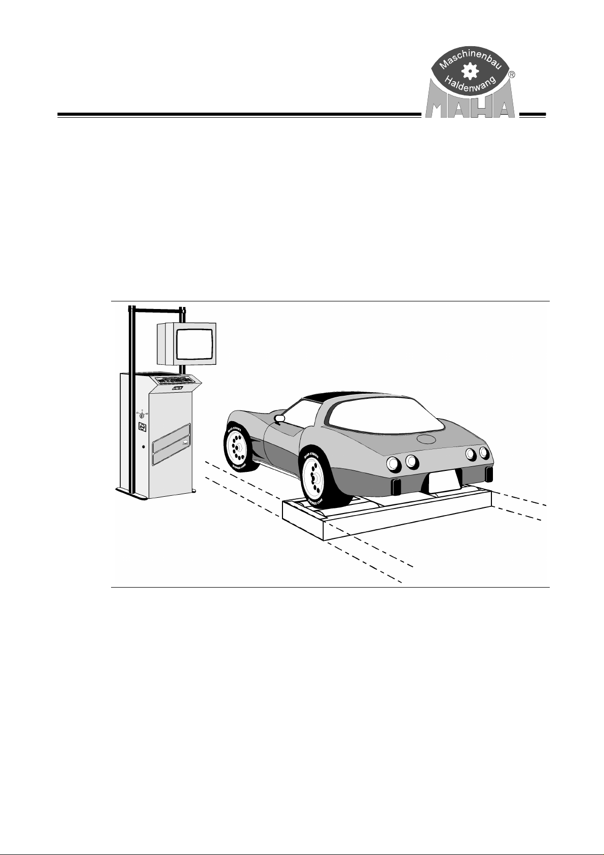
Speedometer Tester
for trucks, passenger cars and transporters
Addition to the operating manual for Eurosystem TRUCK
Original Operating Instructions
D1 1005BA1-GB01
Page 2

TPS II Eurosystem TRUCK
DITION
E
1.edition of this Operating Manual dated 23 October 2000
Addition to the Operating Manual for Eurosystem TRUCK
Eurosystem software version V 2.10
© MAHA GMBH & CO. KG
All rights reserved. Any reproductions of this document, partial or complete, are only allowed
with prior consent of MAHA Gm
ights reserved in cases of patent granting or registration of design.
All r
The contents of this version have been checked with great care. However, errors cannot be fully
excluded. Please contact MAHA should you find errors of any kind.
Subject to technical change without notice.
These instructions are intended for users with previous technical knowledge in the field of
vehicle testing technology and MS Windows operating system applications.
Windows and Windows for Workgroups are registered trademarks of the Microsoft Corporation.
bH & Co. KG
ANUFACTURER
M
ERVICE
S
MAHA Maschinenbau Haldenwang GmbH & Co. KG
Hoy
en 20
D-87490 Haldenwang/Allgäu
Telephone: 08374 / 585-0
Telefax: 08374/ 585-499
Internet: http://www.maha.de
e-mail: maha@maha.de
MAHA Maschinenbau Haldenwang GmbH & Co. KG
- S
ervice Dept. Hoyen 20
D-87490 Haldenwang/Allgäu
Hotline: 08374 / 585 + extension
260 for brake testers, test lanes
280 for lifting technology
290 for performance testers, exhaust and air conditioning service equipment
Service: 08374 / 585-110 to - 113, - 115
Telefax: 08374 / 585-491
II D1 1005BA1-GB01
Page 3

TPS II Eurosystem TRUCK
ABLE OF CONTENTS
T
1 Safety .........................................................................................................................1
1.1 Introduction ....................................................................................................................................1
1.2 Safety Instructions .........................................................................................................................1
2 Description ................................................................................................................3
2.1 Introduction ....................................................................................................................................3
2.2 Usage, Range of Application .........................................................................................................3
2.3 Installation......................................................................................................................................3
2.4 Noise Emission ................................................................................................................. .............4
2.5 Equipment Overview......................................................................................................................4
2.6 Technical Specifications TPS II .....................................................................................................4
3 Operations .................................................................................................................5
3.1 Introduction ....................................................................................................................................5
3.2 Testing Procedure..........................................................................................................................5
3.2.1
3.2.2
3.2.3
3.2.4
3.2.5
3.2.6
Securing the Test Vehicle ..............................................................................................6
Speedometer Test..........................................................................................................6
Travel Distance Test.......................................................................................................8
Storage of Test Values.................................................................................................10
Reviewing of Measurements........................................................................................10
Prepare New Test.........................................................................................................10
4 Maintenance & Troubleshooting............................................................................11
4.1 Maintenance ................................................................................................................................11
4.2 Troubleshooting ...........................................................................................................................12
D1 1005BA1-GB01 III
Page 4

TPS II Eurosystem TRUCK
IV D1 1005BA1-GB01
Page 5

TPS II Eurosystem TRUCK
1 Safety
1.1 Introduction
Please read the standard operating procedures and user’s manual thoroughly and carefully
before commissioning the machinery and comply with the instructions. The operating manual
should always be conveniently stored to be readily available at all times.
This operating manual is an addition to the operating manual for the testing lane Eurosystem
TRUCK. All safety instructions provided in chapter 1 of these operating instructions must be
complied with.
Apart from the safety instructions mentioned above, no additional safety instructions apply for
the operation of the speedometer tester. The speedometer tester is not equipped with any
additional safety features.
1.2 Safety Instructions
The speedometer tester may only be operated by trained, authorized personnel.
The speedometer tester may only be used and operated for its intended purpose: Testing
the tachometer function up to 160 km/h up to 13 t axle load.
Sudden or strong braking actions and jerky accelerations are forbidden.
The vehicle must be secured with tightening belts onto the roller set.
Always drive straight onto the test stand’s rollers. Front-wheel drive vehicles must maintain a
straight driving direction.
Running vehicle engines represent potential carbon monoxide poisoning. The
operator/owner is responsible for providing sufficient air ventilation.
Due to the high noise level (>90 dB), appropriate ear protection should be worn.
No persons are allowed in the vicinity of the rollers while the test stand is in operation!
D1 1005BA1-GB01
1
Page 6

TPS II Eurosystem TRUCK Safety
2
D1 1005BA1-GB01
Page 7

TPS II Eurosystem TRUCK
2 Description
2.1 Introduction
The speedometer tester is designed for vehicles with their speedometer connection at the
driven axle
2.2 Usage, Range of Application
The speedometer tester is a roller tester for the inspection of the speedometer function of
passenger cars and transporters. The speedometer tester permits the measurement of speed
deviation as well as the deviation of the mileage meter.
Trucks, passenger cars and transporters up to a total axle load of 13 t can be tested. The
speedometer tester and the surrounding work area must be kept clean.
The tester is automatically on when the test vehicle is driving at more than 5 km/h on the rollers.
If the speed falls below 5 km/h, the tester switches off automatically.
The recorded measuring values are transmitted to the Eurosystem communication desk and
then displayed on the screen. The storing and the reviewing of measurements is described in
the operating manual for the testing lane Eurosystem TRUCK.
2.3 Installation
The test stand may only be installed and commissioned by the manufacturer's trained
authorized personnel or other qualified technicians of MAHA dealers or representatives. MAHA
instructions must be followed when installing or expanding the testing device.
The manufacturers CE conformity declaration becomes invalid when the installation is not don e
by qualified service technicians. MAHA is not liable for damage caused by unqualified, unautho-
rized installation. Further, the manufacturers warranty also becomes invalid.
D1 1005BA1-GB01 3
Page 8

TPS II Eurosystem TRUCK Description
2.4 Noise Emission
The noise emission test was conducted during the speedometer test, at the highest test speed
of 160 km/h.
Test results
A-evaluated sound pressure level: 105,0 dB(A) (averaged with all measuring points, see
measuring protocol)
A-evaluated acoustic power level: 103,4 dB(A) (calculation based on DIN 45635 Part 1)
Due to the high noise in the test room, ear protection should be worn.
2.5 Equipment Overview
2.6 Technical Specifications TPS II
Max. axle load 13 t
Testing speed 0 to 150 km/h
Weight 950 kg
Tracking width 820 to 2620 mm
Roller diameter 318 mm
Roller length 900 mm
Roller axle separation 457 mm
Dimensions roller set (HxWxL) 400 x 842 x 3000 mm
Air pressur lifting device min. 5 bar
Exit support Pneumatic lifting device with brake
4
D1 1005BA1-GB01
Page 9

TPS II Eurosystem TRUCK
3 Operations
3.1 Introduction
Please also read chapter 3, Eurosystem PC-Program, in the operating manual for the testing
lane Eurosystem TRUCK.
The storing and the reviewing of measurements is described in the operating manual for the
testing lane Eurosystem TRUCK.
3.2 Testing Procedure
In order to start the test procedure, the monitor
must show the main menu. The instruction line
must show the following message:
No vehicle loaded. Select with <1>.
If this message does not appear press
<F8 NEW VEHICLE>.
Now the test lane is ready for a vehicle to be
driven on.
When the vehicle drives onto the individual
equipment the corresponding test screen is
blended in.
Always pay attention to the
(in the description this is indicated by
The recorded measurement values are automatically taken over in the temporary memory and
remain there until they are stored in connection with customer/vehicle or until they are
overwritten when a new test is conducted.
The following guides the user through the testing procedure step by step. You should be familiar
with the usage of the individual screen elements and the keyboard. If this is not the case, please
read the following sections of the operating manual for the testing lane Eurosystem TRUCK:
3.4 Screen Design
3.5 Using the Main Mask
3.6 Using the Button Strip
messages and instructions on the instruction line
Instruction text ).
during testing
D1 1005BA1-GB01
5
Page 10

TPS II Eurosystem TRUCK Operations
3.2.1 Securing the Test Vehicle
It is highly recommended to tie down the test vehicle with a restraining strap system. The tie
plates for fastening the restraining straps are available at the manufacturer. The restraining
strap system avoids skidding of the test vehicle within the roller set.
In order to secure the vehicle, the two restraining straps must be laid around the vehicle’s
towing lug and fixed on the tie plates. Front-wheel drive vehicles have to be secured at the front,
rear-engine drive vehicles at the rear. Cover the restraining straps in the area around the towing
lug with a wear-resistant hose to avoid excessive abrasion.
3.2.2 Speedometer Test
Rotating test stand rollers are potentially dangerous! Risk of injury!
The speedometer tester permits the measurement of the difference between the actual vehicle
speed and the speed displayed on the tachometer of the vehicle.
The speedometer test can be conducted by using the keyboard or the remote control. If a
remote control is not available, a second person will be needed to perform the test.
1 Drive onto the test stand
Drive the driven axle of the vehicle
a.
slowly onto the roller set.
⇒
The vehicle must be positioned
straight
Apply the parking brake.
b.
and
centered
on the roller set.
2 Preparations
Secure the vehicle with tightening belts.
3 Lower lifting device
Press key <T>.
a.
The following screen appears:
Use the <F9> key to select the lifting
b.
device (raise/lower).
Use the <ESC> key to leave this screen.
ATTENTION : Starting from software
version V2.12 the <F4> key must be used
instead of the <T> key to lower the lifting
device. The function of the <F9> key for
switching over the lifting device
(raise/lower) is still the same.
4 Start the testing program
Accelerate the vehicle up to 5 km/h to start
the testing program.
⇒
The screen opposite appears.
6
Accelerate the vehicle to the target value
D1 1005BA1-GB01
Page 11

Operations TPS II Eurosystem TRUCK
The peak of the green arrow indicates the
target speed, the bottom indicates the
tolerance range (±5 km/h). The black arrow
shows the actual speed of the vehicle.
5 Conduct the test
Accelerate the vehicle up to the indicated
target value as per vehicle speedometer.
⇒
The recorded test values will be
displayed.
If the actual speed is within the tolerance
range for 3 sec., the test values will
automatically be stored.
⇒
The next target speed will be indicated.
The measuring value can also be stored by pressing the
target speed. If a remote control is not available, a second person is needed to store the value
by using the keyboard.
Use the
Use the
It is possible to intervene in the automatic test procedure by pressing <F5>. The measuring
values will be stored and the test procedure continues. If the test is repeated, the measuring
values in the temporary memory will be overwritten.
-key to go to the previous target speed.
<F6>
-key to go to the next target speed.
<F7>
6 Repeat the test
The test must be repeated for every target
speed as described in step 4.
The test can be aborted by pressing the
<ESC>-key.
7 Exit the test stand with lift beam
Press <T> on the keyboard or on the
remote control. After the vehicle is lifted,
slowly exit the roller set in forward direction.
key, in order to display the next
<F5>
D1 1005BA1-GB01
7
Page 12

TPS II Eurosystem TRUCK Operations
3.2.3 Travel Distance Test
The speedometer test can be conducted by using the keyboard or the remote control. If a
remote control is not available, a second person will be needed to perform the test.
1 Drive onto the test stand
Drive the driven axle of the vehicle
a.
onto the roller set.
⇒
The vehicle must be positioned
straight
set.
Apply the parking brake.
b.
2 Preparations
Secure the vehicle with tightening belts.
3. Lower lifting device
Press key <T>. The following screen
a.
appears:
Use the <ESC> key to leave this screen.
Use the <F9> key to select the lifting
b.
device (raise/lower).
ATTENTION : Starting from software
version V2.12 the <F4> key must be used
instead of the <T> key to lower the lifting
device. The function of the <F9> key for
switching over the lifting device
(raise/lower) is still the same.
and
centered
on the roller
4 Start the testing program
Accelerate the vehicle up to 5 km/h to start
the testing program.
Ì
The screen opposite appears.
Accelerate the vehicle to the target
value
5. Activate the travel distance test
Press <F8> travel distance to switch to the
corresponding test mode. The screen
opposite appears.
Enter correction factor
The standard setting for the correction
factor is 100%. The correction factor
defines the relation of the tire
circumference on the road to the tire
circumference on the test stand rollers.
8
D1 1005BA1-GB01
Page 13

Operations TPS II Eurosystem TRUCK
6 Conduct the test
a. Enter the mileage of the vehicle via the
number keys of the keyboard or remote
control.
b. Confirm with <RETURN>.
c. Accelerate the vehicle to approx. 20
km/h.
Pay attention to the vehicle’s tachometer.
After a distance of 100 m is traveled press
<F5>. Repeat this process ten times.
⇒
The recorded test values and the
average travel distance will be displayed.
By pressing <F6> the recorded measuring
values will be deleted.
7 Terminate the test
If desired, the test can be aborted with the
<F8> key. The main screen of the
speedometer test appears:
Press <ESC> again to return to the main
menu. In the main menu select <3> „Select
measurement“. Select <6> „External
devices“, then <C> to review the
measuring values. The screen opposite
appears.
8 Exit the test stand with lift beam
Press
remote control. After the vehicle is lifted,
slowly exit the roller set in forward
direction.
The recorded measurement values are automatically taken over in the temporary memory. If the
test is repeated, the measuring values in the temporary memory will be overwritten.
on the keyboard or on the
<T>
D1 1005BA1-GB01
9
Page 14

TPS II Eurosystem TRUCK Operations
3.2.4 Storage of Test Values
The storage of test values is described in the operating manual for the testing lane Eurosystem
TRUCK: ⇒Section 3.17 „Storage of Test Values“.
3.2.5 Reviewing of Measurements
The reviewing of test values is described in the operating manual for the testing lane
Eurosystem TRUCK: ⇒ Section 3.19 „Reviewing of Measurements“.
3.2.6 Prepare New Test
Make sure that the temporary storage is empty for beginning a new test procedure and the main
menu appears with the message:
After properly storing the test values the main menu appears automatically in test readiness. It
is also possible that the instruction line shows a different ready message or that a test has been
aborted and is to be started again from the very beginning.
No vehicle loaded. Select with <1>.
Activate the following box in the main menu:
A message about test readiness appears in the
instruction line
No vehicle loaded. Select with <1>.
:
10
D1 1005BA1-GB01
Page 15

TPS II Eurosystem TRUCK
4 Maintenance & Troubleshooting
4.1 Maintenance
To ensure proper functioning and longevity of the speedometer tester regular servicing
schedules should be followed.
Maintenance schedule:
Lubricate drive shaft once every 200 operating
200 h200 h
hours with universal-type lubricant.
The anchoring of the roller set as well as all
fasteners and screws should be thoroughly
inspected every 200 operating hours.
200 h
200 h200 h
The bearing sleeves of the rollers have
permanent lubrication. Under normal operating
conditions maintenance is not necessary.
D1 1005BA1-GB01
11
Page 16

TPS II Eurosystem TRUCK Maintenance
4.2 Troubleshooting
All work done on electrical parts of the equipment is to be carried out by trained, qualified
electricians or service technicians of the manufacturer or its dealers only. For any kind of
service or repair work the main switch must be switched off and locked.
MALFUNCTION POSSIBLE CAUSE REMEDY
No voltage
Vehicle cannot leave roller set
in backward direction.
Speed indication wrong or no
speed indication
Car lift device (TPS 2) lowers
by itself
Rollers are rotating although
the car lift device is lifted
➀
Voltage has been
interrupted
➁
Control power fuse F1
defective.
➂
Defective transformer fuse.
Free-wheel roller clutch is
defective.
Distance between RPM
impulse sensor and gear is too
large
Loss of pressure in pipe, air
bellow or valve.
Brakes are defective. Replace brakes.
- Restore voltage to
communication desk.
Exchange free-wheel roller
clutch.
Readjust distance (max. 0,8
mm)
Seal up leak or replace faulty
component
12
RPM impulse sensor
A
Drive shaft flange
B
Drive shaft flange
C
Roller
D
Support bracket
E
Bearing
F
Freewheel
G
D1 1005BA1-GB01
Page 17

 Loading...