

Page 1

Fehler! Verwenden Sie die Registerkarte 'Start', um Name dem Text zuzuweisen, der hier angezeigt werden soll.Fehler! Verwenden Sie
die Registerkarte 'Start', um Name dem Text zuzuweisen, der hier angezeigt werden soll.Fehler! Verwenden Sie die Registerkarte
'Start', um Name dem Text zuzuweisen, der hier angezeigt werden soll.
RGE
Mobile Column Lift
Original Operating Instructions
BA490801-en
Pos: 1 /Tec hnisc he Dok um entat ion /Heb e techn ik/ COL UMN LI FT/ 4908 01 R GE/ BA/I nha lt: 49 08 T itelb ild @ 42\mod_1431952788672_0.docx @ 2243711 @ @ 1
Pos: 2 /-----For mat---- -/MAN UELLER UMBRUCH S eitenumb ruch @ 0\m od_ 113 44035 776 87_0. d
Pos: 2 /-----For mat---- -/MAN UELLER UMBRUCH S eitenumb ruch @ 0\m od_11 34403 5776 87_0.d ocx @ 1 277 @ @ 1
Page 2

2
Pos: 3 /-----For mat---- -/Inha ltsv er zeic hnis - 3 Ebene n @ 5\mod_ 116 88674 41046_ 75.do cx @ 729 20 @ @ 1
Contents
1 Safety ...................................................................................................................... 5
1.1 Introduction ......................................................................................................................................... 5
1.2 Symbols .............................................................................................................................................. 5
1.3 Intended Use ....................................................................................................................................... 5
1.4 Inappropriate Use ................................................................................................................................ 5
1.5 Requirements on Operating and Service Personnel ............................................................................. 5
1.6 Safety Instructions for Commissioning ................................................................................................. 6
1.7 Safety Instructions for Operation ......................................................................................................... 6
1.8 Safety Instructions for Servicing ........................................................................................................... 6
1.9 What to Do in the Event of Defects or Malfunctions ............................................................................. 6
1.10 What to Do in the Event of an Accident ............................................................................................... 6
1.11 Safety Features ................................................................................................................................... 8
1.11.1 Locking Device .................................................................................................................................... 8
1.11.2 Braking Motor ..................................................................................................................................... 8
1.11.3 Phase Sequence Relay........................................................................................................................ 8
1.11.4 Thermal Overload Protection ............................................................................................................... 8
1.11.5 Safety Shutdown after Motor Overload ................................................................................................ 8
1.11.6 Warning and Information Labels .......................................................................................................... 8
2 Description ............................................................................................................... 9
2.1 General Information ............................................................................................................................. 9
2.2 Noise Emission .................................................................................................................................... 9
2.3 Specifications ...................................................................................................................................... 9
2.4 Sample Nameplate ............................................................................................................................ 12
3 Operation ............................................................................................................... 13
3.1 Handling / Moving the Columns ........................................................................................................ 13
3.2 Installing the Power Supply Unit ........................................................................................................ 14
3.3 Lift Positioning ................................................................................................................................... 14
3.4 Controls ............................................................................................................................................ 16
3.5 Main Switch....................................................................................................................................... 17
3.6 Emergency Stop................................................................................................................................ 17
3.7 Operating Modes .............................................................................................................................. 17
3.7.1 Automatic Mode ................................................................................................................................ 17
3.7.2 Single Mode ...................................................................................................................................... 18
3.7.3 Group Mode ...................................................................................................................................... 19
3.7.4 Cable Remote Control ....................................................................................................................... 19
3.8 Emergency-down Function, Mechanical ............................................................................................ 20
3.9 RGE GPGU: Adjustment of Support Forks ........................................................................................ 21
3.10 Operation with more than 6 Columns ................................................................................................ 21
3.11 Transverse Beam for Semitrailers ...................................................................................................... 22
4 Maintenance .......................................................................................................... 23
BA490801-en
Page 3

3
4.1 Annual Inspection .............................................................................................................................. 23
4.2 Care Instructions ............................................................................................................................... 23
4.3 Spare Parts ....................................................................................................................................... 23
4.4 Maintenance by the Operator ............................................................................................................ 24
4.4.1 Recirculating Ball Nut ........................................................................................................................ 24
4.4.2 Moving Gear ...................................................................................................................................... 25
4.4.3 Options ............................................................................................................................................. 25
4.4.4 Thrust Washers ................................................................................................................................. 26
4.5 Setting the Hydraulic Jack ................................................................................................................. 29
5 Display Codes ........................................................................................................ 30
6 Service Lifetime ...................................................................................................... 32
7 Dismantling ............................................................................................................ 32
8 Disposal ................................................................................................................. 32
9 Contents of the Declaration of Conformity .............................................................. 32
10 Company Information ............................................................................................. 33
Pos: 4 /-----For mat---- -/MAN UELLER UMBRUCH S eitenumb ruch @ 0\m od_11 34403 5776 87_0.d ocx @ 1 277 @ @ 1
BA490801-en
Page 4

4
Pos: 5 /-----For mat---- -/MAN UELLER UMBRUCH S eitenumb ruch @ 0\m od_11 34403 5776 87_0.d ocx @ 1 277 @ @ 1
BA490801-en
Page 5
5
1
Safety
1.1
Introduction
1.2
Symbols
1.3
Intended Use
1.4
Inappropriate Use
1.5
Requirements on Operating and Service Personnel
Pos: 6 /Technische D okumen tation/A lle Ger äte/ Überschr iften/ Übersc hriften 1/S/Üb erschri ft 1: Si cher heit @ 6\mod_1174482399906_75.docx @ 76962 @ 1 @ 1
Pos: 7 /Techn ische Dokum en tati on/A lle Ger äte/ Über schr ifte n/Über schr iften 1.1/ E/Über sc hrif t 1.1: E inf ühru ng @ 6\ mod_1174482219062_75.docx @ 76793 @ 2 @ 1
Pos: 8 /Technisc he Dokum enta tion/ All e Gerä te/In halte/ Sic herhe it/In halt : Ei nführ ung S icher hei t @ 6\mod_1175609639562_75.docx @ 87528 @ @ 1
Thoroughly read this manual before operating the equipment and comply with the instructions.
Always display the manual in a conspicuous location.
Personal injury and property damage incurred due to non-compliance with these safety
Pos: 9 /Technische D okumen tation/A lle Ger äte/ Überschr iften/ Übersc hriften 1.1/S/ Überschr ift 1. 1: Sym bole @ 6\mod_1174482270875_75.docx @ 76865 @ 2 @ 1
Pos: 10 /Techn ische Dokume ntatio n/Alle G eräte/ Inhalte/ Sicher heit/In halt: Sy mbole S icherh eit @ 14\mod_1239866667866_75.docx @ 361518 @ @ 1
instructions are not covered by the product liability regulations.
Important safety instructions. Failure to comply with instructions could result in personal injury or
property damage.
Important information.
Pos: 11 /Technische Dokument ation/Alle Gerät e/Übersc hriften/Üb erschriften 1. 1/B/Übers chrift 1.1: Bestimm ungsgemä ßer Gebrauch @ 6\mod_117 6734 02220 3_75.d ocx @ 88746 @ 2 @ 1
Pos: 12 /Tec hn isch e Do kument ation/H ebetech nik/C OLUMNLI FT/490 001 Rad greifer -Hebeb ühnen A lle/Inh alte/In halt: Bestimm ungs gemäßer G ebra uch RG -HBZ @ 11\ mod_1227608538981_75.docx @ 275048 @ @ 1
• This lift is to be used exclusively for the safe lifting of commercial and agricultural vehicles such
as trucks, buses, tractors etc. Observe the rated load capacity.
• The lift may not be modified without the express written consent of the manufacturer. In case of
Pos: 13 /Technische Dokument ation/Alle Gerät e/Übersc hriften/Üb erschriften 1. 1/B/Übers chrift 1.1: Bestimm ungswid riger Gebrauc h @ 18\mod_1255530265027_75.docx @ 471571 @ 2 @ 1
Pos: 14 /Techn ische Dok ument atio n/Heb etechni k/- Ar chiv -/00 H ebetech nik - Alle/In halte/Inha lt: Bestimmungsw idriger Gebr auch HBZ @ 19\mod_1267188702628_75.docx @ 794843 @ @ 1
non-compliance the declaration of conformity becomes void.
Any use other than described is inappropriate, for example:
• Climbing on the lift supports
• Transporting persons on the lift supports
Pos: 15 /Technische Dokume ntatio n/Alle Geräte/ Übersc hriften/ Überschr iften 1.1/A/ Übersc hrift 1.1: Anf order ungen a n das Bedien ungs- und Ser vicep ersonal @ 34\mod_1380637497630_75.docx @ 1835413 @ 2 @ 1
Pos: 16 /Technische Dokume ntatio n/Alle Geräte/ Inhalte/ Sicher heit/In halt: Anf order ungen a n das Bedie nungs- und Servicep ersonal @ 35\mod_1390296255225_75.docx @ 1876648 @ @ 1
• Usage as mobile work platform or for other lifting operations
All persons employed in the operation, maintenance, installation, removal and disposal of the
device must
• be at least 18 years old,
• be trained and instructed in writing,
• have read and understood this manual
• be on record as having been instructed in safety guidelines.
Pos: 17 /Technische Dokume ntatio n/Alle Geräte/ Übersc hriften/ Überschr iften 1.1/S/ Übersc hrift 1.1: Sic herheit svorschr iften f ür di e Inbe triebnahm e @ 6\m od_1174482269156_75.docx @ 76838 @ 2 @ 1
BA490801-en
Page 6

6
1.6
Safety Instructions for Commissioning
1.7
Safety Instructions for Operation
1.8
Safety Instructions for Servicing
1.9
What to Do in the Event of Defects or Malfunctions
1.10
What to Do in the Event of an Accident
Pos: 18 /Tec hnisch e Dok ument ation/H ebetech nik/C OLUMNLI FT/490 001 Rad greifer -Hebeb ühnen A lle/Inh alte/In halt: S icher heitsvorsc hrif ten für d ie Inb etrieb nahme RG-H BZ @ 6\m od_1178094134921_75.docx @ 90757 @ @ 1
• Use the lift on a hard, level surface only.
• The standard lift version may not be installed and commissioned in the vicinity of explosives or
Pos: 19 /Technische Dokume ntatio n/Alle Geräte/ Übersc hriften/ Überschr iften 1.1/S/ Übersc hrift 1.1: Sic herheit svorschr iften f ür den Betri eb @ 6\m od _11 7448 2268 953_ 75.docx @ 7682 6 @ 2 @ 1
Pos: 20 /Technische Dokume ntatio n/Hebet echnik /COL UMNLIFT/ 490001 Radgr eifer-Heb ebühne n Alle/ Inhal te/Inhal t: Sicher heitsv orschr iften für den Betr ieb RG-H BZ @ 6\mod_1178094657921_75.docx @ 90770 @ @ 1
flammable liquids.
• Read the detailed operating manual.
• Lift operation by trained personnel over 18 years only.
• Do not exceed the rated load capacity per column as indicated on the lift nameplate.
• Ensure an unobstructed movement of lift and vehicle.
• After raising the vehicle briefly, stop and check the lift supports for secure contact with the
vehicle.
• Closely watch lift and vehicle during raising and lowering cycles.
• The working area which cannot be overviewed by the operator should be monitored by a
second person.
• When operating the lift in single or group mode, make sure the vehicle is not tilted.
• Do not allow anyone to stay in lift area during raising and lowering cycles.
• Do not allow anyone to climb on lift or inside raised vehicle.
• Keep lift and vehicle free of tools and parts.
• When using the lift outdoors, lower the vehicle and stop operation when the wind velocity
exceeds 6 m/s.
• Push the support forks completely under the wheels or lift points of the vehicle to be raised.
Pos: 21 /Technische Dokume ntatio n/Alle Geräte/ Übersc hriften/ Überschr iften 1.1/S/ Übersc hrift 1.1: Sic herheit svorschr iften f ür Serv icearbe iten @ 6\mod_1174482270640_75.docx @ 76850 @ 2 @ 1
• Do not drive over or pinch electrical cables.
Pos: 22 /Tec hnisch e Dokum entat ion/Heb etech nik/COL UMNLIF T/4900 01 Rad greifer -Hebebü hnen A lle/Inh alte/In halt: Si cherhei tsvorsc hriften für Servicear beiten RG-H BZ @ 6\mod _117 80952 27937_ 75.d ocx @ 907 93 @ @ 1
• Service work may be done by authorized service technicians only.
• Turn off and padlock the main switch before doing any repair, maintenance or setup work.
• Disconnect the mains plug before opening the control box.
• Work on the electrical equipment may be done by service technicians or certified electricians
only.
• Ensure that ecologically harmful substances are disposed of only in accordance with the
appropriate regulations.
• Do not use high pressure or steam jet cleaners. Use of caustic cleaning agents may damage
the lift.
Pos: 23 /Technische Dokument ation/Alle Gerät e/Übersc hriften/Üb erschriften 1. 1/V/Übersc hrift 1.1: Verhal ten im Störfall @ 6\mod_1178097008375_75.docx @ 90829 @ 2 @ 1
Pos: 24 /Technische Dokume ntatio n/Hebet echnik/ - Arch iv -/ 00 H ebet echni k - Alle/I nha lte/ I nhalt : V erh alte n im St örf all H BZ @ 19\mod_1267177095494_75.docx @ 794570 @ @ 1
• Do not replace or override the lift safety devices.
• In case of defects or malfunctions such as uncontrolled lift movement or deformation of the
superstructure, support or lower the lift immediately.
Pos: 25 /Technische Dokume ntatio n/Alle Geräte/ Übersc hriften/ Überschr iften 1.1/V /Übersc hrift 1 .1: Ver halten bei U nfällen @ 19\m od_ 126 7177245337_75.docx @ 794600 @ 2 @ 1
• Turn off the main switch and secure it against unauthorized usage. Contact service.
BA490801-en
Page 7

7
Pos: 26 /Technische Dokument ation/Alle Gerät e/Inhalte/ Sicherhe it/Inhalt: Verha lten bei Unfälle n @ 34\mod_1381128804654_75.docx @ 1837123 @ @ 1
• The injured person is to be removed from the danger area. Find out where dressing and
bandages are kept. Seek first-aid.
• Provide first-aid (stop bleeding, immobilise injured limbs), report the accident and seal off the
accident site.
• Immediately report any accident to your supervisor. Make sure a record is kept of every
occasion first-aid is provided, e.g. in an accident book.
Pos: 27 /-----For ma t-----/MA N UEL LER UMB RUC H Se ite num br uch @ 0\m od_1134403577687_0.docx @ 1277 @ @ 1
• Remain calm and answer any questions that may arise.
BA490801-en
Page 8
8
1.11
Safety Features
1.11.1
Locking Device
1.11.2
Braking Motor
1.11.3
Phase Sequence Relay
1.11.4
Thermal Overload Protection
1.11.5
Safety Shutdown after Motor Overload
≥ 15 %
1.11.6
Warning and Information Labels
Pos: 28 /Tec hnisch e Dokume ntation/ Alle Gerät e/Übers chrift en/Über schrifte n 1.1/S/ Übersc hrift 1.1: S icherhe itseinr ichtunge n @ 6\mod_ 1174 4833 24765_ 75.do cx @ 7710 3 @ 2 @ 1
Pos: 29 /Technische Dokume ntatio n/Hebet echnik /COL UMNLIFT/ 490001 Radgr eifer-Heb ebühne n Alle/ Inhal te/Inhal t: Sicher heitse inrich tungen RG-H BZ @ 1 7\mod_1250235608088_75.docx @ 427993 @ 333333 @ 1
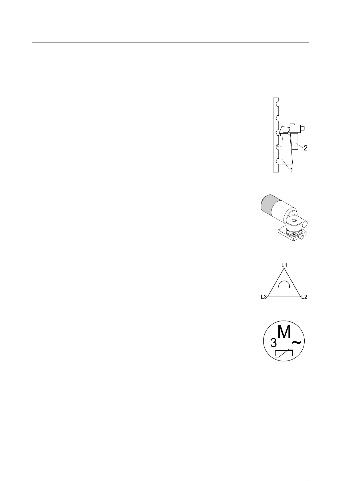
The locking device serves to prevent inadvertent lowering motions caused by gear,
load nut or lifting screw failure. The carriage is blocked by safety wedge (1) and
counterwedge (2).
The motors are equipped with AC spring pressure brakes. Once the motors
are switched off, the brakes prevent any further movements.
The phase sequence relay in the power supply unit ensures safe and
independent operation.
Overload protection via electronically monitored thermoswitches.
The motor load is permanently monitored by the control PCB. If an overload of
system will switch off automatically. In this case the lift cannot be raised any more, but it can be
normally lowered to bottom position.
Do not change or remove the warning and information labels. Order replacement for defective
Pos: 30 /-----For ma t-----/MA N UEL LER UMB RUC H Se ite num br uch @ 0\m od_1134403577687_0.docx @ 1277 @ @ 1
labels.
occurs, the
BA490801-en
Page 9

9
2
Description
2.1
General Information
2.2
Noise Emission
2.3
Specifications
RGE
RGE GPGU
RGE T
Pos: 31 /Technische Dokume ntatio n/Alle Geräte/ Übersc hriften/ Übersc hriften 1/ B/Über schrift 1: Beschre ibung @ 6\mod_1174482271453_75.docx @ 76889 @ 1 @ 1
Pos: 32 /Technische Dokument ation/Alle Gerät e/Übersc hriften/Üb erschriften 1. 1/A/Übersc hrift 1.1: Allgem eines @ 6\mod_1182865005781_75.docx @ 97736 @ 2 @ 1
Pos: 33 /Technische Dokume ntatio n/Papier korb/ Hebete chnik/In halt: B eschr eibung A llgeme ines RGE @ 17\mod_1250243858131_75.docx @ 428020 @ @ 1
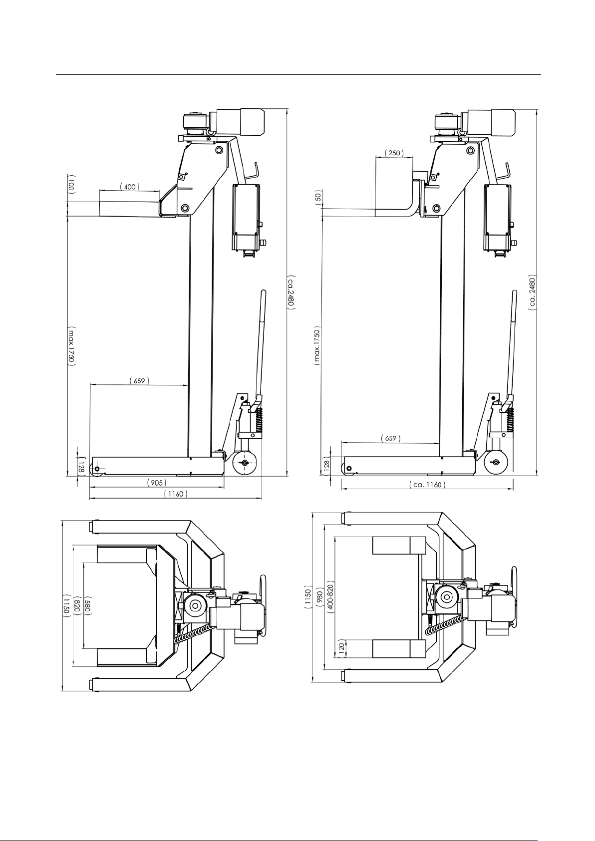
The mobile column lifts of the RGE series are produced as wheel engaging or universal lifts.
Depending on the version, the lift system consists of 2 or 4 columns and can be expanded to 6
columns in the standard version.
The lift can be expanded up to 12 columns when using a special power supply unit.
All components are easily accessible under the lifted vehicle due to a generous maximum lifting
height of 1750 mm.
The lift is a mobile unit whereby the columns can be substituted with stands when vehicles are to
Pos: 34 /Technische Dokument ation/Alle Gerät e/Übersc hriften/Üb erschriften 1. 1/L/Übers chrift 1.1: Lärmem ission @ 13\mod_1236767272078_75.docx @ 354579 @ 2 @ 1
Pos: 35 /Technische Dokume ntatio n/Hebet echnik /- Arc hiv -/ 00 H ebetech nik - Alle/ In halt e/I nha lt: S cha lld ru ckpe gel < 70 d B(A) @ 14\mod_1241593887290_75.docx @ 371013 @ @ 1
Pos: 36 /Technische Dokument ation/Alle Gerät e/Übersc hriften/Üb erschriften 1. 1/T/Übers chrift 1.1: Technis che Daten @ 7\mod_1184075526343_75.docx @ 99711 @ 2 @ 1
be worked on for a longer period of time. The lifting columns are free to be used on other vehicles.
The sound pressure level is lower than 70 dB(A) in the working area of the operator.
Pos: 37 /Technische Dokume ntatio n/Hebet echnik /COL UMNLIF T/4 908 01 RG E/ BA/ Inh alt: 490 8 Te chn isc he Date n ( Tabe lle ) @ 1 8\mod_1256046112218_75.docx @ 480360 @ @ 1
Load capacity per column 7500 kg 7500 kg 5000 kg
Full travel 1750 mm 1750 mm 1750 mm
Raising / Lowering time 113 s 113 s 113 s
Raising speed 0.92 m/min 0.92 m/min 0.92 m/min
Tyre diameter 900…1250 mm --- 600…2000 mm
Motor power 1.5 kW 1.5 kW 1.5 kW
System of protection IP 54 IP 54 IP 54
Supply voltage 3~ 380/220 V; 50 Hz 3~ 400 V; 50 Hz 3~ 400 V; 50 Hz
Net weight per column 452 kg 502 kg 542 kg
Surface load 0.5 N/mm2 0.5 N/mm2 0.5 N/mm2
Pos: 38 /Technische Dokume ntatio n/Hebet echnik /- Arc hiv -/ 00 H ebetech nik - Alle/I nha lte/I nfo!/In ha lt: Inf o - B etriebs warmer Zustand / Te chn. Änd erung en HBZ @ 6\mod_1177427042703_75.docx @ 90160 @ @ 1
The properties indicated apply to lifts running at operating temperature.
Specifications are subject to change without notice.
Pos: 39 /-----For ma t-----/MA N UEL LER UMB RUC H Se ite num br uch @ 0\mod_1134403577687_0.docx @ 1277 @ @ 1
BA490801-en
Page 10
10
RGE
RGE GPGU
Pos: 40 /Technische Dokument ation/Papier korb/Heb etechnik/In halt: Technisch e Daten (Bilder) RGE /RGE GPGU @ 18\m od_ 12 560 396 613 10_0.d ocx @ 479 921 @ @ 1
Pos: 41 /-----For ma t-----/MA NUE LL ER UM BR UCH Se iten um bru ch @ 0\mod_1134403577687_0.docx @ 1277 @ @ 1
BA490801-en
Page 11

11
RGE T
Pos: 42 /Technische Dokument ation/Papier korb/Heb etechnik/In halt: Technisch e Daten (Bilder) RGE T @ 18\mod_1256042847810_0.docx @ 479948 @ @ 1
Pos: 43 /-----For ma t-----/MA N UEL LER UMB RUC H Se ite num br uch @ 0\m od_1134403577687_0.docx @ 1277 @ @ 1
BA490801-en
Page 12

12
2.4
Sample Nameplate
Pos: 44 /Technische Dokument ation/Alle Gerät e/Übersc hriften/Üb erschriften 1. 1/T/Übers chrift 1.1: Type nschild-Mus ter @ 1 1\mod _12 276 222 06096_ 7 5.docx @ 27557 4 @ 2 @ 1
Pos: 45 /Technische Dokume ntatio n/Hebet echnik /COL UMNLIFT/ 490001 Radgr eifer-Heb ebühne n Alle/ Inhal te/Inhal t: Type nschi ld-Must er RG -H BZ MAH A @ 2 4\mod_1309945137131_75.docx @ 1021484 @ @ 1
MOBILE COLUMN LIFT
Ser.No. / Date of Production: ***
Project: ***
Type: ***
Charging Voltage: ***
Operating Voltage: ***
Net weight per column: ***
Load capacity per column: ***
System of Protection: ***
WEEE Reg. No. ***
Pos: 46 /-----For ma t-----/MA N UEL LER UMB RUC H Se ite num br uch @ 0\m od_1134403577687_0.docx @ 1277 @ @ 1
BA490801-en
Page 13

13
3
Operation
3.1
Handling / Moving the Columns
Pos: 47 /Technische Dokument ation/Alle Gerät e/Übersc hriften/Üb erschriften 1/ B/Überschri ft 1: Bedienung @ 6\mod_1174482271218_75.docx @ 76877 @ 1 @ 1
Pos: 48 /Technische Dokume ntatio n/Alle Geräte/ Übersc hriften/ Überschr iften 1.1/T/ Übers chrift 1.1: Tra nsport / Vers chiebe n von H ubs äule n @ 12\ mod_1231486358029_75.docx @ 300405 @ 2 @ 1
Pos: 49 /Technische Dokume ntatio n/Hebet echnik /COL UMNLIFT/ 490801 RGE/ BA/Inhal t: 490 8 Transp ort/V erschieb en ( Bilder) @ 12\mod_1231486938020_0.docx @ 300505 @ @ 1
Pos: 50 /Technische Dokume ntatio n/Papier korb/ Hebete chnik/In halt: Transport/ Verschi eben (Text) RGE @ 12\mod_1231486726149_75.docx @ 300480 @ @ 1
Screw a lifting-eye bolt M16 into the tap hole on the motor plate of the column. Insert a chain or
strap through the ring and lift the column using a hoist or forklift.
Close hydraulic valve by putting valve lever in position 3.
Pump with handle to raise the moving gear. Move column to desired position.
To lower the moving gear, open the hydraulic valve by putting the valve lever in position 1. The
column is ready for operation.
Pos: 51 /-----For ma t-----/MA N UEL LER UMB RUC H Se ite num br uch @ 0\m od_1134403577687_0.docx @ 1277 @ @ 1
Position 2 is the neutral position.
BA490801-en
Page 14

14
3.2
Installing the Power Supply Unit
3.3
Lift Positioning
Connection Diagram
B
1
V
2
E
3
A
Pos: 52 /Technische Dokume ntatio n/Alle Geräte/ Übersc hriften/ Überschr iften 1.1/A/ Übersc hrift 1.1: Aufs tecken d er Versorg ungse inhe it @ 24\mod_1310375912170_75.docx @ 1022557 @ 2 @ 1
Pos: 53 /Technische Dokume ntatio n/Hebet echnik /COL UMNLIFT/ 490801 RGE/ BA/Inhal t: 490 8 Vers orgun gseinhei t (Bild) @ 12\mod_1231747186755_0.docx @ 300870 @ @ 1
Pos: 54 /Technische Dokume ntatio n/Papier korb/ Hebete chnik/In halt: Ver sor gungsei nheit RGE (Tex t) @ 1 2\mod_1231747307958_75.docx @ 300895 @ @ 1
Attach the power supply unit (V) to the left-hand sidewall of the control unit (B), as seen from the
Pos: 55 /Technische Dokument ation/Alle Gerät e/Übersc hriften/Üb erschriften 1. 1/A/Übersc hrift 1.1: Aufs tellen der Hebebüh ne @ 12\mod_1231747750802_75.docx @ 301020 @ 2 @ 1
Pos: 56 /Technische Dokume ntatio n/Papier korb/ Hebete chnik/In halt: A nschlusss chem a RGE ( Tex t) @ 12\m od_1231748550599_75.docx @ 301095 @ @ 1
Pos: 57 /Technische Dokume ntatio n/Hebet echnik /COL UMNLIFT/ 490801 RGE/ BA/Inhal t: 490 8 Ansc hlusssc hema ( Bilder) @ 12\mod_1231748798771_0.docx @ 301120 @ @ 1
controls, to ensure easy accessibility of the main switch.
Connecting Cable
Dummy Plug
Mains Plug
Control Unit
Power Supply Unit
Input Terminal
Output Terminal
BA490801-en
Page 15

15
Pos: 58 /Technische Dokume ntatio n/Papier korb/ Hebete chnik/In halt: A ufstel len der Hebebü hne ( Teil 1) @ 12\mod_1231748934630_75.docx @ 301145 @ @ 1
• Use the lift on a hard, level surface only, preferably concrete.
• Apply the parking brake after positioning the vehicle.
• Push the support forks completely under the wheels/lift points of the vehicle.
• Attach the power supply unit (V) to the control unit (B) of the column closest to the mains
socket.
• Interconnect the columns using connecting cables (1) between input terminals (E) and output
terminals (A). Connect a dummy plug or the remote control (2) to the output terminal of the last
Pos: 59 /Technische Dokume ntatio n/Hebet echnik /- Arc hiv -/ 00 H ebetech nik - Alle/In halte/War nung!/ Inhalt: Warnung - Verlegte Kabel @ 1 2\mod_1231749063771_75.docx @ 301170 @ @ 1
column.
Do not drive over or pinch electrical cables.
Pos: 60 /Technische Dokume ntatio n/Hebet echnik /- Arc hiv -/ 00 H ebetech nik - Alle/I nha lte/I nfo!/In ha lt: Inf o - Au fstellen der H ebebü hne @ 12\mod_1231749115349_75.docx @ 301205 @ @ 1
Secure the connecting cable plugs using the safety clamps.
The plugs and terminals are coded.
Pos: 61 /Technische Dokume ntatio n/Papier korb/ Hebete chnik/In halt: A ufstel len der Hebebü hne ( Teil 2) @ 12\mod_1231749215146_75.docx @ 301230 @ @ 1
• Connect the mains plug (3) of the master column with the 400 V mains socket. Recheck the
electrical connections.
Pos: 62 /-----For mat -----/MAN UE LLE R UM BR UCH Se iten umb ruc h @ 0\mod_1134403577687_0.docx @ 1277 @ @ 1
• Once the main switch is turned on, the lift is ready for operation.
BA490801-en
Page 16

16
3.4
Controls
V
B
1
2
3
4
5
6
7
Pos: 63 /Technische Dokument ation/Alle Gerät e/Übersc hriften/Üb erschriften 1. 1/B/Übers chrift 1.1: Bedien elemente @ 13\m od_12 37975 0991 77_7 5.docx @ 35900 8 @ 2 @ 1
Pos: 64 /Technische Dokume ntatio n/Hebet echnik /COL UMNLIFT/ 490801 RGE/ BA/Inhal t: 490 8 Bedi enelem ente (Bi lder) @ 25\mod_1319463749099_0.docx @ 1065861 @ @ 1
Pos: 65 /Technische Dokume ntatio n/Papier korb/ Hebete chnik/In halt: B ediene lement e RGE ( Text) @ 12\mod_1231490810014_75.docx @ 300760 @ @ 1
Power Supply Unit
Main Switch
LED Display
Indicates operating and error states.
Selector Button (on Control Unit)
Use this button to select between: Automatic / Single / Group mode
Seven-Segment Display (on Control Unit)
Indicates operating and error codes.
RAISE Button (on Control Unit)
Press and hold this button to raise the lift. Lift stops once button is released or upward travel
stop is reached.
LOWER Button (on Control Unit)
Press and hold this button to lower the lift. Lift stops once button is released or downward
travel stop is reached.
Emergency Stop Button (on Control Unit)
In case of emergency press this button to disconnect the lift from the mains supply.
Pull out the button to make the lift ready for operation.
Pos: 66 /-----For ma t-----/MA N UEL LER UMB RUC H Se ite num br uch @ 0\m od_1134403577687_0.docx @ 1277 @ @ 1
Control Unit
BA490801-en
Page 17

17
3.5
Main Switch
3.6
Emergency Stop
To make the lift ready for operation, unlock the emergency stop button and switch off the lift briefly
3.7
Operating Modes
3.7.1
Automatic Mode
Pos: 67 /Technische Dokume ntatio n/Alle Geräte/ Übersc hriften/ Überschr iften 1.1/H /Überschr ift 1 .1: Haup tschalter @ 6\mod_11 77592 8583 12_7 5.docx @ 90635 @ 2 @ 1
Pos: 68 /Technische Dokume ntatio n/Hebet echnik /- Arc hiv -/ 00 H ebetech nik - Alle/ In halt e/I nha lt: H a uptsc ha lter m it No t-Aus- Funkt ion HBZ @ 22\m od_1295874475528_75.docx @ 964591 @ @ 1
The main switch is used as emergency switch. In case of emergency turn it to position 0.
• Main switch in position 0: Power supply is interrupted
• Main switch in position 1: Lift is ready for operation
• When in position 0, the main switch can be protected against tampering
by means of a padlock.
Pos: 69 /Technisch e Dok ument ation/Al le Gerät e/Übers chrift en/Über schrif ten 1. 1/N/Über schr ift 1.1: N ot-Ha lt-S chalter @ 12\m od_1 23176 26854 15_7 5.docx @ 30208 5 @ 2 @ 1
Pos: 70 /Technische Dokume ntatio n/Papier korb/ Hebete chnik/In halt: N ot-Ha lt @ 12\mod_1231763835049_75.docx @ 302215 @ @ 1
Pos: 71 /Technische Dokume ntatio n/Hebet echnik /- Arc hiv -/ 00 H ebetech nik - Alle/I nha lte/I nfo!/In ha lt: Inf o - Not-Halt @ 12\mod_1231764019369_75.docx @ 302260 @ @ 1
In case of emergency push the emergency stop button to stop the lift movement immediately.
using the main switch.
Pos: 72 /Technische Dokument ation/Alle Gerät e/Übersc hriften/Üb erschriften 1. 1/B/Übers chrift 1.1: Betriebs arten @ 14\mod _12 4228 26630 93_75.d ocx @ 37 5477 @ 2 @ 1
Pos: 73 /Technische Dokument ation/Alle Gerät e/Übersc hriften/Üb erschriften 1. 1.1/A/Üb ers chr if t 1.1 .1: Aut oma tik- Bet rieb @ 1 2\mod_ 12317 53241 005_ 75.do cx @ 3015 80 @ 3 @ 1
Pos: 74 /Technische Dokume ntatio n/Papier korb/ Hebete chnik/In halt: A utomat ik-Be trieb RGE @ 12\m od_1231753348068_75.docx @ 301635 @ @ 1
Select "Automatic mode" by pressing this button on each column.
Activation of this operating mode is indicated by the letter A on the seven-
segment display.
Use these buttons on the control unit to raise or lower the lift.
Pos: 75 /Tec hn ische Do kumentat ion/Hebetech nik/- Arc hiv -/ 00 H ebetech nik - Alle/I nha lte/I nfo!/I nha lt: Inf o - Au tomatikbetr ieb RGE @ 12\mod_1231754332521_75.docx @ 301660 @ @ 1
After switch-on the lift is in automatic mode.
Pos: 76 /-----For ma t-----/MA N UEL LER UMB RUC H Se ite num br uch @ 0\m od_1134403577687_0.docx @ 1277 @ @ 1
BA490801-en
Page 18

18
3.7.2
Single Mode
Pos: 77 /Technische Dokument ation/Alle Gerät e/Übersc hriften/Üb erschriften 1. 1.1/S/Übers chrift 1.1.1 : Single-Betrieb @ 12\mod_1231750604943_75.docx @ 301400 @ 3 @ 1
Pos: 78 /Technische Dokume ntatio n/Hebet echnik /- Arc hiv -/ 00 H ebetech nik - Alle/Inhalte/Warnung!/Inhalt: Warnung - Einzelbetr ieb RG @ 2 0\mod_1268321800281_75.docx @ 824738 @ @ 1
When operating the lift in Single mode, make sure the vehicle is not tilted. Otherwise the vehicle
may fall off the lift!
Pos: 79 /Technische Dokume ntatio n/Papier korb/ Hebete chnik/In halt: S ingle-B etrieb (mit Warnun g) RGE @ 20\mod_1268321049708_75.docx @ 824703 @ @ 1
Select "Single mode" by pressing this
button on the desired column.
Activation of this operating mode is
indicated by the lit LED on the selector
button and the letter S on the sevensegment display.
The columns not in Single mode are
temporarily inoperative. This is indicated by
the letter A flashing on the seven-segment
display.
Use these buttons to raise or lower the lift. or
Pos: 80 /Tec hn ische Do kumentat ion/Hebetech nik/- Arc hiv -/ 00 H ebetech nik - Alle/I nha lte/I nfo!/I nha lt: Inf o - Ver schiedene H ubsäulen RGE @ 12\m od_1231755449651_75.docx @ 301710 @ @ 1
The single mode can also be used for several columns simultaneously
Pos: 81 /Technische Dokume ntatio n/Hebet echnik /- Arc hiv -/ 00 H ebetech nik - Alle/I nha lte/I nfo!/In ha lt: Inf o - Si ngle -Be trieb RGE @ 1 2\mod_1231756197190_75.docx @ 301735 @ @ 1
Height offsets between individual columns will be maintained after switch-over to automatic mode.
The offset can be removed either
– by equalizing the carriages in single mode or
– by lowering all carriages to bottom position in automatic mode.
• Lift switches off once first carriage reaches upward travel stop.
Pos: 82 /-----For ma t-----/MA N UEL LER UMB RUC H Se ite num br uch @ 0\m od_1134403577687_0.docx @ 1277 @ @ 1
BA490801-en
Page 19

19
3.7.3
Group Mode
3.7.4
Cable Remote Control
Pos: 83 /Technische Dokume ntatio n/Alle Geräte/ Übersc hriften/ Überschr iften 1.1. 1/G/Übers chrif t 1.1.1 : Gruppe n-Betr ieb @ 12\mod_1231756478332_75.docx @ 301760 @ 3 @ 1
Pos: 84 /Technische Dokume ntatio n/Hebet echnik /- Arc hiv -/ 00 H ebetech nik - Alle/Inhalte/Warnung!/Inhalt: Warnung - Gruppenbetrieb RG @ 20\mod_1268321843218_75.docx @ 824769 @ @ 1
When operating the lift in Group mode, make sure the vehicle is not tilted. Otherwise the vehicle
may fall off the lift!
Pos: 85 /Technische Dokume ntatio n/Papier korb/ Hebete chnik/In halt: Gr uppe n-Betrieb (mi t Warnu ng) RGE @ 21\mod_1281958619825_75.docx @ 879733 @ @ 1
Select "Group mode" by pressing and
holding this button for approx. two
2 sec
seconds.
Activation of this operating mode is
indicated by the lit LED on the selector
button and the letter G on the sevensegment display.
The columns not in Group mode are
temporarily inoperative. This is indicated by
the letter A flashing on the seven-segment
display.
Use these buttons to raise or lower the lift. or
Pos: 86 /Technische Dokument ation/Alle Gerät e/Übersc hriften/Üb erschriften 1. 1.1/K/Über schrift 1.1. 1: Kabelfernbed ienung @ 12\mod_1231757725696_75.docx @ 301860 @ 3 @ 1
Pos: 87 /Technische Dokume ntatio n/Papier korb/ Hebete chnik/In halt: K abelfer nbedienun g RGE @ 12\mod_1231758115175_75.docx @ 301885 @ @ 1
A remote control (model TCNA 10-2) is optionally available.
The RAISE, LOWER and Emergency Stop buttons have the same functions as the corresponding
Pos: 88 /Technische Dokume ntatio n/Hebet echnik /- Arc hiv -/ 00 H ebetech nik - Alle/I nha lte/I nfo!/In ha lt: Inf o - Kab elf ernb edienu ng RG E @ 12\mod_1231760974987_75.docx @ 301950 @ @ 1
buttons on the column control units.
Except for the emergency stop button, the remote control is not usable in single mode.
Pos: 89 /-----For ma t-----/MA N UEL LER UMB RUC H Se ite num br uch @ 0\m od_1134403577687_0.docx @ 1277 @ @ 1
BA490801-en
Page 20

20
3.8
Emergency-down Function, Mechanical
Pos: 90 /Technische Dokume ntatio n/Alle Geräte/ Übersc hriften/ Überschr iften 1.1/N /Überschr ift 1 .1: No tab-Funktion, mechanisch @ 15\mod_12452 5092 1286_7 5.doc x @ 3907 49 @ 2 @ 1
Pos: 91 /Technische Dokume ntatio n/Hebet echnik /- Arc hiv -/ 00 H ebetech nik - Alle/Inhalte/Warnung!/Inhalt: Warnung - Manuelles Abse nke n nur durc h ges chu ltes P ers onal @ 6\mod_1180962217687_75.docx @ 95217 @ @ 1
Authorized personnel only! Do not restart the lift before the error has been remedied.
Pos: 92 /Technische Dokume ntatio n/Papier korb/ Hebete chnik/In halt: M anuel les Abs enken RGE/RG A @ 24\mod_1310108278807_75.docx @ 1022148 @ @ 1
In case of power failure or defects the lift can be lowered manually.
Once the locking device is in engagement, manual lowering is no longer possible.
The following components are required for manual lowering:
A Lever at brake motor B Locking device
1 Pull or shake the safety wedge downward on each column.
2 First push onto the latch using a long screw driver, then additionally push the manual release
lever (in arrow direction).
Intermittently lower the columns in increments of approx. 50 mm (2 in), until the lift is in bottom
Pos: 93 /-----For ma t-----/MA NUEL LER UM BRUC H Zeile nscha ltun g @ 7\mod_ 1195 1389 65731_ 0.doc x @ 13217 7 @ @ 1
Pos: 94 /Technische Dokume ntatio n/Hebet echnik /COL UMNLIFT/ 490801 RGE/ BA/Inhal t: 490 8 Manu elles Absenken RGE/RGA (Bilder ) @ 42\mod_1433145052043_0.docx @ 2249463 @ @ 1
position.
Pos: 95 /-----For ma t-----/MA N UEL LER UMB RUC H Se ite num br uch @ 0\m od_1134403577687_0.docx @ 1277 @ @ 1
BA490801-en
1
2
Page 21

21
3.9
RGE GPGU: Adjustment of Support Forks
3.10
Operation with more than 6 Columns
A
B
C
D
E
Branch 2 Branch 1
A
B
D
E
B
C
C
OUT
OUT
OUT
IN
IN
IN
IN
IN
IN
IN IN
OUT
OUT OUT OUT
OUT OUT OUT
D
Pos: 96 /Technische Dokume ntatio n/Alle Geräte/ Überschrift en/Überschr iften 1.1/F/ Überschrif t 1.1: Fahrzeu gaufnahme der RGE GPG U anpassen @ 12\mod_1231764099824_75.docx @ 302285 @ 2 @ 1
Pos: 97 /Technische Dokume ntatio n/Papier korb/ Hebete chnik/In halt: F ahrzeu gauf nahm e (Tex t) @ 12\mod_1231764290176_75.docx @ 302335 @ @ 1
The fork width can be adjusted to different wheel sizes.
• Remove cotter pin (1).
• Lift the front end of the fork (2) and adjust as required (3).
• Let the fork lock into place using one of the location holes and secure by inserting the cotter
Pos: 98 /Techn ische Dok ument atio n/Heb etech nik /COL UMNLI FT/4 908 01 RGE/ BA/ Inhal t: 4 908 Fahrze ugauf na hme ( Bild) @ 12\m od_1231764181416_0.docx @ 302310 @ @ 1
pin.
Pos: 99 /Technische Dokument ation/Alle Gerät e/Übersc hriften/Üb erschriften 1. 1/B/Übers chrift 1.1: Betrieb m it mehr als 6 Hubsäu len @ 8\mod _120 33413 48470_ 75.d ocx @ 14 7360 @ 2 @ 1
Pos: 100 /Technische Dokum entati on/Pap ierkorb /Hebetec hnik/I nhalt: Betrieb m it m ehr als 6 Hub säule n (Tex t) RGE @ 24\mod_1310385829100_75.docx @ 1022781 @ @ 1
Using the optionally available special control unit, the RGE lift can be operated with up to 12
columns – 2 column branches with 6 columns each.
Special control unit
Control unit
Pos: 101 /Tech nische Dok umen tati on/Heb ete chnik/ COL UMNLI FT/ 490 801 RG E/BA/ Inha lt: 490 8 Betri eb m it me hr a ls 6 H ubsä ulen ( B ild) @ 24\mod_1310385917208_0.docx @ 1022797 @ @ 1
Connecting cable
Dummy plug or Cable remote control
Power cord with Mains plug
Pos: 102 /-----F orm at-----/M ANUELLE R UMBR UCH Seite numbru ch @ 0\mod_1134403577687_0.docx @ 1277 @ @ 1
BA490801-en
Page 22

22
3.11
Transverse Beam for Semitrailers
Pos: 103 /Technis che Dok umen tation/A lle Ger äte/Üb erschr iften/Üb erschr iften 1 .1/A/Üb erschr ift 1.1: Aufna hmetr averse f ür Sa ttelauf lieger @ 6\mod_1178182588031_75.docx @ 91050 @ 2 @ 1
Pos: 104 /Te ch nisc he D ok umen tati on/H ebe te chn ik/C OLUM NLI FT/ 49 000 1 Rad gre ifer -Hebeb ühnen Alle/I nhalte/ Inhalt: A ufnahm etraver se für Sat telauflieg er (B ilder) @ 15\m od_12 43954 4317 70_0.d ocx @ 3 85024 @ @ 1
Pos: 105 /Te ch nisc he D ok umen tati on/H ebe te chn ik/C OLUM NLI FT/ 49 000 1 Rad gre ifer -Hebeb ühnen Alle/I nhalte/ Inhalt: A ufnahm etraver se für Sat telauflieg er (T ext) @ 15\mod_1243954387004_75.docx @ 384993 @ @ 1
A Support plate with location hole for central pivot of semitrailer
B Lift points for support forks
1 Position transverse beam under central pivot (C) of semitrailer.
2 Lower semitrailer until central pivot is approx. 20 mm above support plate (A).
Do not load the rollers of the transverse beam with the weight of the semitrailer.
3 Check for alignment of central pivot and location hole. Adjust if required.
4 Position the columns.
Pos: 106 /-----F orm at-----/ MAN UEL LE R UMB R UCH S eite numbru ch @ 0\mod_1134403577687_0.docx @ 1277 @ @ 1
5 Raise the semitrailer being sure the central pivot engages the location hole.
BA490801-en
Page 23

23
4
Maintenance
4.1
Annual Inspection
12 (twelve) months
4.2
Care Instructions
4.3
Spare Parts
Pos: 107 /Tech nische Dok umen tati on/P apierk orb /Über schri ften/ Über schr ift 1: Ins tand haltun g @ 11\mod_1231318736629_75.docx @ 289550 @ 1 @ 1
Pos: 108 /Technische Dokum entati on/Alle G eräte/Inhalte/Warnung!/Inhalt: Warnung - Hauptschalter aus be i Ins tandha ltun g @ 14\mod_1240239070975_75.docx @ 362949 @ @ 1
Danger! Electric shock hazard!
Before doing any maintenance work, turn off the main switch and protect it against tampering.
Pos: 109 /Tech nische Dok umen tati on/P apierk orb /Über schri ften/ Über schr ift 1.1: J ährl iche Überp rüfu ng @ 6\m od_117 4482 24571 8_75.d ocx @ 768 17 @ 2 @ 1
Pos: 110 /Tech nische Dok umen tati on/A lle G eräte/ Inha lte/ Info!/I nha lt: Inf o - Jährlich e Überprüfun g @ 14\mod_1242051457491_75.docx @ 373548 @ @ 1
• The maintenance interval prescribed by the manufacturer is
This maintenance interval refers to normal workshop usage. If the equipment is used more
frequently or under severe operating conditions (e.g. outdoors), the interval must be reduced
accordingly.
• Maintenance work shall be done only by authorized and trained service technicians provided by
the manufacturer, licensed dealers or service partners.
• In case of non-compliance the manufacturer's warranty becomes void.
Pos: 111 /Te ch nisc he D ok umen tati on/H ebe te chn ik/- Arch iv -/0 0 Hebe technik - All e/Inh alte/ Inf o!/In halt: I nf o - DG UV Rege l 10 0-500 / DGUV Grundsatz 308-003 @ 47\mod_1484557193623_75.docx @ 2810767 @ @ 1
Pos: 112 /Technis che Dok umen tation/A lle Ger äte/Üb erschr iften/Üb erschr iften 1 .1/P/Üb erschr ift 1.1: Pfle gehinwe ise @ 15\mod_1245912234854_75.docx @ 395780 @ 2 @ 1
Pos: 113 /Tech nische Dok umen tati on/A lle G eräte/ Inha lte/ Inhalt : Pf lege hinwe ise - Alle Geräte @ 2 4\mod_1303909841314_75.docx @ 999500 @ @ 1
• Periodically clean the equipment and treat it with a care product.
• Repair damage to the paintwork immediately to prevent corrosion.
• Usage of caustic cleaning agents or high pressure and steam jet cleaners may lead to
Pos: 114 /Tech nische Dok umen tati on/A lle G eräte/ Inha lte/ Info!/I nha lt: Inf o - Pflegehinweise @ 24\mod_1304338389761_75.docx @ 1002352 @ @ 1
equipment damage.
.
Regular care and maintenance is the key condition for functionality and long life expectancy of the
equipment!
Pos: 115 /Technische Dokum entati on/Alle G eräte/ Übers chrifte n/Über schrifte n 1.1/E/ Über schrift 1.1: Ers atzte ile @ 18\mod_1255596847002_75.docx @ 474414 @ 2 @ 1
Pos: 116 /Te ch nisc he D ok umen tati on/A ll e Ge räte/ In ha lte/ Inha lt: Ers atz te ile - A lle Ger äte @ 20\mod_1267189216113_75.docx @ 794936 @ @ 1
To ensure safe and reliable operation, only use original spare parts supplied by the equipment
Pos: 117 /-----F orm at-----/ MAN UEL LE R UMB R UCH S eite num br uch @ 0\mod_1134403577687_0.docx @ 1277 @ @ 1
manufacturer.
BA490801-en
Page 24

24
4.4
Maintenance by the Operator
4.4.1
Recirculating Ball Nut
Pos: 118 /Tech nische Dok umen tati on/P apierk orb /Über schri ften/ Über schr ift 1.1: Ins ta ndha ltung d urc h de n Betre iber @ 6\mod _1178 5435 44390_ 75.d ocx @ 91 370 @ 2 @ 1
Pos: 119 /Technische Dokum entati on/Alle G eräte/ Übers chrifte n/Über schrifte n 1.1.1/ K/Über schr ift 1.1.1 : Kug elumlaufm utter @ 14\m od_1 24150 68922 27_7 5.docx @ 37008 3 @ 3 @ 1
Pos: 120 /Te ch nisc he D ok umen tati on/H ebe te chn ik/C OLUM NLI FT/ 49 000 1 Radgre ifer-Heb ebüh nen A lle/Inha lte/Inh alt: Ins t. durch den Betreiber - K ugelum laufm utt er RGE @ 8\ mod_1203344483645_75.docx @ 147411 @ @ 1
Twice a year grease the recirculating ball nut with 4…7 strokes from a grease gun. The lubricator is
located at the recirculating ball nut inside the carriage.
To make the lubricator accessible, remove the
screws (1 and 3). Then remove cover plate (4)
and fastening strip of rubber cover (2).
Fold down the rubber cover.
Pos: 121 /-----F orm at-----/M ANUELLE R UMBR UCH Seite numbru ch @ 0\mod_1134403577687_0.docx @ 1277 @ @ 1
BA490801-en
Page 25

25
4.4.2
Moving Gear
4.4.3
Options
Pos: 122 /Technische Dokum entati on/Alle G eräte/ Übers chrifte n/Über schrifte n 1.1.1/F/Überschrift 1.1.1: Fahrgestellrollen @ 14\mod_1241509024011_75.docx @ 370175 @ 3 @ 1
Pos: 123 /Te ch nisc he D ok umen tati on/H ebe te chn ik/C OLUM NLI FT/ 49 000 1 Rad gre ifer -Hebeb ühnen Alle/I nhalte/ Inhalt: I nst. d urch d en Be treiber - Fahr geste llro llen RG E @ 8\mod_1203344747789_75.docx @ 147428 @ @ 1
Periodically oil the rollers of the moving gear.
If they are equipped with lubricators, lubricate
using a grease gun.
Pos: 124 /Te ch nische Dok umentati on/Alle G eräte/ Übers chrifte n/Über schrif ten 1.1 .1/O/Üb erschr ift 1.1. 1: Opt ionen @ 14\mod _1 24150 97831 81_75.d ocx @ 3 70221 @ 3 @ 1
Pos: 125 /Te ch nisc he D ok umen tati on/H ebe te chn ik/C OLUM NLI FT/ 49 000 1 Rad gre ifer -Hebeb üh nen A lle/I nha lte/Inh alt: I nst. dur ch den Betreiber - Op tione n RGE @ 9\mod_1216216694188_75.docx @ 229210 @ @ 1
Recirculating ball nuts with outside lubricator
(option) should be greased every six months
with four to seven strokes from a grease gun.
Pos: 126 /-----F orm at-----/M ANUELLE R UMBR UCH Seite numbru ch @ 0\mod_1134403577687_0.docx @ 1277 @ @ 1
Carriage axles equipped with a lubricator
(option) should be periodically greased using a
grease gun.
BA490801-en
Page 26

26
4.4.4
Thrust Washers
Visual Inspection with Feeler Gauge
2 mm
2 mm
Pos: 127 /Te ch nisc he D okumen tation/A lle G eräte/ Überschr iften/Üb erschr iften 1 .1.1/A/ Übers chrift 1.1.1: A nlaufsc heiben @ 4 9\mod_1493215373635_75.docx @ 2874053 @ 3 @ 1
Pos: 128 /Te ch nisc he D ok umen tati on/H ebe te chn ik/C OLUM NLI FT/ 49 080 1 RGE /BA/ I nhalt : 490 8 | 49 19 A nla ufsc he iben - Prü fung Blattlehre ( Text) @ 49\mod_1493213099568_75.docx @ 2874006 @ @ 1
Once a month check the bronze thrust washers for wear using a feeler gauge (see illustration).
New thrust washers have a thickness of 2 mm. Once a single washer shows signs of excessive
Pos: 129 /Tech nische Dok umen tati on/Heb ete chnik/ COL UMNLI FT/ 49 080 1 RGE /BA/ I nhalt : 49 08 | 49 19 A nla ufsc he iben - Pos iti on a uf We lle ( Bild ) @ 49\ mod_ 149 32093 79772_ 0.docx @ 2873 818 @ @ 1
wear (more than 1 mm), it must be replaced.
Pos: 130 /Te ch nisc he D ok umen tati on/H ebe te chn ik/C OLUM NLI FT/ 49 080 1 RGE /BA/ I nhalt : 490 8 | 49 19 A nlaufs che iben - Pr üfung Blattl ehre (Bild) @ 49\mod_1493210270178_0.docx @ 2873865 @ @ 1
Pos: 131 /-----F orm at-----/M ANUELLE R UMBR UCH Seite numbru ch @ 0\mod_1134403577687_0.docx @ 1277 @ @ 1
BA490801-en
Page 27

27
Shaking Test on Lifting Carriage
WARNING
Pos: 132 /Te ch nisc he D ok umen tati on/H ebe te chn ik/C OLUM NLI FT/ 49 080 1 RGE /BA/ I nhalt : 490 8 | 49 19 A nla ufsc he iben - Rü tteltes t (Text) @ 49\ mod_1493215607721_75.docx @ 2874101 @ @ 1
In addition to the visual inspection, perform a shaking test on the lifting carriage every three
months. To do this, hold the carriage firmly by the support fork, then pull it forward making a
Pos: 133 /Te ch nisc he D ok umen tati on/H ebe te chn ik/C OLUM NLI FT/ 49 080 1 RGE /BA/ I nhalt : 490 8 | 49 19 A nla ufsc he iben - Hubschlitten richtig (Bilder) @ 49\mod_1493210805624_0.docx @ 2873912 @ @ 1
twisting movement.
If the guide rollers jump out of the guide track during the shaking test, the lifting column must be
shut down until the thrust washers have been replaced.
Pos: 134 /-----F orm at-----/M ANUELLE R UMBR UCH Seite numbru ch @ 0\mod_1134403577687_0.docx @ 1277 @ @ 1
BA490801-en
Page 28

28
Pos: 135 /Te ch nisc he D ok umen tati on/H ebe te chn ik/C OLUM NLI FT/ 49 080 1 RGE /BA/ I nhalt : 490 8 | 49 19 A nla ufsc he iben - Hubs chl itte n falsc h ( Bilder ) @ 49\mod_1493212319415_0.docx @ 2873959 @ @ 1
Pos: 136 /-----F orm at-----/M ANUELLE R UMBR UCH Seite numbru ch @ 0\mod_1134403577687_0.docx @ 1277 @ @ 1
BA490801-en
Page 29

29
4.5
Setting the Hydraulic Jack
A: Setting the Lowering Speed
Threaded Pin
Lowering Speed
B: Setting the Responsiveness of the Automatic Lowering Function
Adjusting Screw
Responsiveness
A B
Pos: 137 /Technische Dokum entati on/Alle G eräte/ Übers chrifte n/Über schrifte n 1.1/E/ Über schrift 1.1: E instell ungen am hydr aulische n Fahrw agen @ 24\mod_1302611581158_75.docx @ 994317 @ 2 @ 1
Pos: 138 /Te ch nisc he D ok umen tati on/H ebe te chn ik/C OLUM NLI FT/ 49 000 1 Rad gre ifer -Hebeb ühnen Alle/I nhalte/ Inhalt: E inst. am hydr . Fahrw agen ( Bilder ) RG-H BZ @ 24\m od_13 02257 2526 08_0.d ocx @ 9 93783 @ @ 1
Pos: 139 /Te ch nisc he D ok umen tati on/H ebe te chn ik/C OLUM NLI FT/ 49 000 1 Rad gre ifer -Hebeb ühnen Alle/I nhalte/ Inhalt: E inst. am hydr. Fahrw agen (Tex t) RG-HBZ @ 2 4\mod_1302259063767_75.docx @ 993823 @ @ 1
Note that the jack must be mounted to the column when making any settings.
The lowering valve is located on the right-hand side of the cylinder. To set the lowering speed,
adjust the threaded pin using an Allen key while holding the lock nut firmly with an open-end
wrench. Check for correct setting by carefully lowering the jack.
Pos: 140 /Te ch nisc he D okumen tation/A lle G eräte/ Überschr iften/Üb erschr iften 1/ D/Üb erschrif t 1: D isplay-C odes @ 20\ mod_1268322303622_75.docx @ 824793 @ 1 @ 1
OPEN
CLOSE
INCREASE
REDUCE
The automatic lowering valve is located on the left-hand side of the cylinder. Remove the screw
plug using an Allen key, then insert a flat-tip screwdriver to set the adjusting screw. Soak up
leaking fluid with a rag. Reinstall the screw plug.
OPEN
CLOSE
REDUCE
INCREASE
BA490801-en
Page 30

30
5
Display Codes
Display Code
LED
Cause
Action
Pos: 141 /Te ch nisc he D ok umen tati on/H ebe te chn ik/C OLUM NLI FT/ 49 080 1 RGE /BA/ I nhalt : 490 8 Disp lay -Cod es @ 39\mod_1408972336479_75.docx @ 2081930 @ @ 1
Green
Yellow on
1 or
several
columns
Yellow on
1
column,
Green on
all others
Red on
1 column
Normal operation, no errors.
See "Operating Modes;
Automatic Mode, Single Mode and
Group Mode in this manual.
Uncontrolled operation.
Bus line failure.
CAN bus without terminating resistor. Check terminating resistors of CAN bus
CAN controller out of step or
defective.
Controller in sleep mode due to shortcircuit of CAN lines.
Safety switch triggered.
Carriage has made contact with
obstacle.
Thermoswitch triggered.
Overheated motor. Lift stops and
error message appears.
Normal operation.
Replace connecting cable.
in dummy plug and power supply unit,
contact service.
Turn the main switch off and on again.
If error persists, contact service.
Replace connecting cable. Contact
service if necessary.
Switch column with error message to
single mode. Raise carriage to unlock
the safety wedge or remove obstacle.
Let the motor cool down. Check
thermoswitch, motor and column.
Acknowledge error with selector button
on control panel.
Red LED will go out and the lift is ready
for operation.
BA490801-en
Yellow on
all
columns
Red on
all
columns
Insufficient speed / Overspeed.
Lift stops when irregular motor speed
is detected.
Overloaded lift.
Maximum permissible load exceeded. Lower lift to bottom position.
Release control element. The error is
removed and the lift is ready for
operation.
Acknowledge error with selector button
on control panel.
Page 31

31
Display Code
LED
Cause
Action
Red on
all
columns
Red on
all
columns
Red on
all
columns
Red on
all
columns
Red on 1
or several
columns
Proximity switch defective.
Proximity switch defective due to
short-circuit or broken wire.
Height difference between columns.
Maximum permissible height
difference exceeded.
CAN bus error.
CAN bus connection was briefly
interrupted.
Phase failure of supply system.
The lift stops and remains inoperative
until power supply has been restored.
Phase failure of lift system.
Phase failure of lift system due to
defective connecting cable.
Proximity switch must be replaced,
contact service. Acknowledge error
with selector button on control panel.
Turn the main switch off and on again.
Zeroize the lift by lowering each column
to bottom position in single mode. If
error persists, contact service.
Turn the main switch off and on again.
Lower lift to bottom position. Red LED
will go out and the lift is ready for
operation.
Remove phase failure.
Replace faulty connecting cable.
Red on
all
columns
Pos: 142 /-----F orm at-----/M ANUELLE R UMBR UCH Seite numbru ch @ 0\mod_1134403577687_0.docx @ 1277 @ @ 1
Cyclic Redundancy Check error.
Hardware error occurred while data
being read from or written to the
EEPROM.
PCB must be replaced, contact service.
BA490801-en
Page 32

32
6
Service Lifetime
7
Dismantling
8
Disposal
9
Contents of the Declaration of Conformity
MAHA Maschinenbau Haldenwang GmbH & Co. KG
Model:
Designation:
Directives:
Standards:
Pos: 143 /Technische Dokum entati on/Alle G eräte/ Übers chrifte n/Über schrifte n 1/L/ Übersc hrift 1: Leben sdauer @ 19\mod _12 66336 76155 0_75.d ocx @ 74 2423 @ 1 @ 1
Pos: 144 /Te ch nisc he D ok umen tati on/H ebe te chn ik/- Arch iv -/0 0 Hebe technik - Alle/ Inhal te/Inhal t: Lebe nsda uer HBZ @ 21\mod_1284715576070_75.docx @ 893652 @ @ 1
In its standard version, this product is designed for 22,000 load cycles based on EN 1493.
The maximum period of normal use in relation to the possible product life expectancy shall be
Pos: 145 /Technische Dokum entati on/Alle G eräte/ Übers chrifte n/Über schrifte n 1/D/Üb ers chrift 1: Demon tage @ 19\m od_12 66336 8228 63_75. docx @ 74 2452 @ 1 @ 1
Pos: 146 /Technische Dokum entati on/Alle G eräte/I nha lte/Inha lt: Dem ontage - Alle Geräte @ 19\mod_1266331670825_75.docx @ 742336 @ @ 1
evaluated and scheduled by a qualified person during the annual safety inspection.
Decommissioning and dismantling of the equipment may be done only by specially authorized and
Pos: 147 /Te ch nisc he D okumen tation/A lle G eräte/ Überschr iften/Üb erschr iften 1/ G/Über schr ift 1: Ger ätee ntsorg ung @ 6\mod_1174482271625_75.docx @ 76901 @ 1 @ 1
Pos: 148 /Technische Dokum entati on/Alle G eräte/I nha lte/Inha lt: Ger äteents orgung ( ohne RiLi) @ 21\mod_1276527534762_75.docx @ 856673 @ @ 1
trained personnel provided by the manufacturer, licensed dealers or service partners.
If you want to dispose of the equipment, please contact your MAHA dealer or the following
address, indicating equipment type, date of purchase and serial number:
MAHA Maschinenbau Haldenwang GmbH & Co. KG
Hoyen 20
87490 Haldenwang
Germany
Phone: +49 (0) 8374 585 0
Fax: +49 (0) 8374 585 500
Pos: 149 /Technische Dokum entati on/Alle G eräte/I nha lte/Inha lt: Ger äteents orgung über F achbetr ieb (a lternat iv) @ 19\mod_1266331765399_75.docx @ 742365 @ @ 1
Email: altgeraete@maha.de
Alternatively, you may take the equipment to a specialised waste management plant to ensure that
Pos: 150 /Technische Dokum entati on/Alle G eräte/ Übers chrifte n/Über schrifte n 1/I/ Überschr ift 1: I nhal t der Konform itäts erkl ärung @ 22\ mod_1292856748432_75.docx @ 958616 @ 1 @ 1
all components and operating liquids are properly disposed of.
Pos: 151 /Technische Dokum entati on/Alle G eräte/I nha lte/Inha lt: Inha lt der Konfor mitäts erkläru ng all g @ 24\mod_1306229196727_75.docx @ 1011543 @ @ 1
herewith declares as a manufacturer its sole responsibility to ensure that the product named
hereafter meets the safety and health regulations both in design and construction required by the
EC directives stated below.
This declaration becomes void if any change is made to the product that was not discussed and
Pos: 152 /Te ch nisc he D ok umen tati on/H ebe te chn ik/C OLUM NLI FT/ 49 080 1 RGE /BA/ I nhalt : 490 8 Inh alt d er Konf ormitätserk lärung @ 45\mod_1468919630453_75.docx @ 2541182 @ @ 1
Pos: 153 /-----F orm at-----/M ANUELLE R UMBR UCH Seite numbru ch @ 0\mod_1134403577687_0.docx @ 1277 @ @ 1
approved by named company beforehand.
RGE / RGE GPGU / RGE T / RGE TS
Mobile Column Lift; Rated Load Capacity per Column 5000 / 7500 kg
2006/42/EC; 2014/30/EU
EN 1493; EN 60204-1
BA490801-en
Page 33

10 Company Information
© MAHA Maschinenbau Haldenwang GmbH & Co. KG
Legal notice based on ISO 16016:
The reproduction, distribution and utilization of this document as well as the communication of its
contents to others without explicit authorization is prohibited. Offenders will be held liable for the
payment of damages. All rights reserved in the event of the grant of a patent, utility model or design.
The contents of this edition have been checked with great care. However, errors cannot be fully
excluded. Subject to technical change without notice.
Document
Document No.: BA490801-en
Approval Date: 2017-05-30
Manufacturer
MAHA Maschinenbau Haldenwang GmbH & Co. KG
Hoyen 20
87490 Haldenwang
Germany
Phone: +49 8374 585 0
Fax: +49 8374 585 590
Mail: maha@maha.de
Web: http://www.maha.de
33
Service
MAHA SERVICE CENTER
AutomoTec GmbH
Maybachstraße 8
87437 Kempten
Germany
Phone: +49 8374 585 100
Fax: +49 8374 585 491
Mail: service@automo-tec.com
Web: www.automo-tec.com
BA490801-en
 Loading...