

MAHA POWERDYNO MSR, POWERDYNO MSR 500, POWERDYNO MSR 1000, POWERDYNO MSR 1050, POWERDYNO MSR 800 Original Operating Instructions
...Page 1

Fehler! Verwenden Sie die Registerkarte 'Start', um Name dem Text zuzuweisen, der hier angezeigt werden soll.Fehler! Verwenden Sie
die Registerkarte 'Start', um Name dem Text zuzuweisen, der hier angezeigt werden soll.Fehler! Verwenden Sie die Registerkarte
'Start', um Name dem Text zuzuweisen, der hier angezeigt werden soll.
MSR
Single Roller Dynamometer
Original Operating Instructions
BA053101-en
Pos: 1 /Technische D okumen tation/A lle Ger äte/T iteltex te/Titel text: MS R - Alle Typen @ 24\mod_1303997516266_0.docx @ 1000449 @ @ 1
MSR 500
MSR 800
MSR 830
MSR 850
MSR 1000
MSR 1050
Pos: 2 /Tec hnisc he Dok um entat ion /Le istu ngsm es ste chn ik/P OWE RDYN O/ 053 101 M S R/B A/In halt : 05 31 Tite lbild @ 42\ mod_ 1435 0441 04527_ 0.docx @ 22584 84 @ @ 1
Pos: 2 /-----For mat---- -/MAN UELLER UMBRUCH S eitenumb ruch @ 0\m od_11 34403 5776 87_0.d ocx @ 1 278 @ @
Pos: 3 /-----For mat---- -/MAN UELLER UMBRUCH S eitenumb ruch @ 0\m od_11 34403 5776 87_0.d ocx @ 1 277 @ @ 1
Page 2

2
1
Safety .................................................................................................................. 7
2
Description ........................................................................................................ 12
Pos: 4 /-----For mat---- -/Inh altsv er zeic hn is - 3 Eb e nen @ 5\m od_11 68867 4410 46_75. docx @ 72 920 @ @ 1
Contents
1.1 Introduction .............................................................................................................. 7
1.2 Symbols ................................................................................................................... 7
1.3 Intended Use ........................................................................................................... 7
1.4 Safety Instructions for Commissioning ...................................................................... 7
1.5 Safety Instructions for Operation............................................................................... 8
1.6 Safety Instructions for Servicing ................................................................................ 9
1.7 Danger Zone .......................................................................................................... 10
1.8 Safety Information about Tires ................................................................................ 10
1.9 Safety Information about the Eddy Current Brake ................................................... 11
1.10 Safety Features ...................................................................................................... 11
1.11 Accessories ........................................................................................................... 11
1.12 What to Do in the Event of an Accident .................................................................. 11
2.1 General Information ................................................................................................ 12
2.2 Specifications ......................................................................................................... 13
2.2.1 Dimensions ............................................................................................................ 13
2.2.2 Communication Desk ............................................................................................. 15
2.2.3 MSR 500/1 ............................................................................................................ 16
2.2.4 MSR 500/2 ............................................................................................................ 17
2.2.5 MSR 500/2 4WD .................................................................................................... 18
2.2.6 MSR 500/3 4WD .................................................................................................... 19
2.2.7 MSR 800 ............................................................................................................... 20
2.2.8 MSR 830 ............................................................................................................... 21
2.2.9 MSR 850 ............................................................................................................... 22
2.2.10 MSR 1000 ............................................................................................................. 23
2.2.11 MSR 1050 ............................................................................................................. 24
2.3 Main Switch ........................................................................................................... 25
2.4 Controls and Indicators .......................................................................................... 25
2.5 Emergency Stop .................................................................................................... 26
2.6 Remote Control ...................................................................................................... 27
2.7 Description of the Interface Box .............................................................................. 29
2.7.1 RPM Module (Standard) ......................................................................................... 31
2.7.2 Environmental Module (Standard) ........................................................................... 33
2.7.3 OBD Module (Optional)........................................................................................... 34
BA053101-en
Page 3

3
3
Description of the SINAMICS Components .......................................................... 44
4
Transport and Storage ....................................................................................... 47
5
Installation and Initial Operation ........................................................................... 47
6
Installation ......................................................................................................... 47
7
Software ............................................................................................................ 51
8
Preparations for Testing...................................................................................... 59
2.7.4 Pressure/Temperature Module (Optional) ................................................................ 34
2.7.5 Analog Input Module (Optional) ............................................................................... 35
2.8 Analog Output Card (Optional) ................................................................................ 35
2.9 Measurement Programs ......................................................................................... 36
2.10 Calculation Basis .................................................................................................... 37
2.10.1 Road Load ............................................................................................................. 37
2.10.2 Torque ................................................................................................................... 38
2.10.3 Extrapolation of the Engine Power with Gasoline Engines ....................................... 39
2.10.4 Extrapolation of the Engine Power with Diesel Engines (Naturally Aspirated or
Supercharged) .................................................................................................................... 40
2.10.5 Extrapolation of the Engine Power with Turbodiesel Engines ................................... 41
2.10.6 Calculate Engine Factor fm ..................................................................................... 42
2.10.7 4 Wheel Drive Operation ......................................................................................... 43
3.1 Special Safety Instructions for the SINAMICS Components .................................... 44
3.2 Mains Connection for Booksize Drive Assembly ...................................................... 45
3.3 Basic Setup ........................................................................................................... 46
6.1 Requirements for the Place of Installation ............................................................... 47
6.2 Safety Measures .................................................................................................... 47
6.2.1 Heat Balance ......................................................................................................... 47
6.2.2 Exhaust Suction System ......................................................................................... 49
6.2.3 Fresh Air Supply for the Test Room ........................................................................ 50
7.1 System Requirements ............................................................................................ 51
7.2 Starting the Setup .................................................................................................. 51
7.3 Selecting the Setup Language ................................................................................ 52
7.4 Selecting the Destination Folder ............................................................................. 53
7.5 Selecting the SQL Server ....................................................................................... 53
7.6 Selecting the Dyno Type......................................................................................... 54
7.7 Selecting Features .................................................................................................. 54
7.8 Installing Drivers ..................................................................................................... 55
7.9 Finishing the Setup ................................................................................................. 55
7.10 Additional Settings under Windows 7 or higher ....................................................... 56
BA053101-en
Page 4

4
9
Program Structure ............................................................................................. 63
10
Measurements ................................................................................................... 69
8.1 Switch on the Dyno ................................................................................................ 59
8.2 Drive onto Dyno and Secure Vehicle ....................................................................... 59
8.3 Connect the RPM Sensor ....................................................................................... 60
8.4 Connect Oil Temperature Probe ............................................................................. 61
8.5 Attach Exhaust Suction System .............................................................................. 61
8.6 Position Cooling Air Fan ......................................................................................... 61
8.7 Bring the Vehicle up to Operating Temperature ...................................................... 62
8.8 Vehicle Ready for Testing ....................................................................................... 62
8.9 Exit the Dynamometer ............................................................................................ 62
9.1 General Information ................................................................................................ 63
9.2 Tree Model ............................................................................................................. 64
9.3 Screen Design ........................................................................................................ 65
9.3.1 Status Line ............................................................................................................. 65
9.3.2 Main Screen ........................................................................................................... 67
9.3.3 Button Bar ............................................................................................................. 67
9.4 Starting the Program .............................................................................................. 68
9.5 End Program / Switch off Dyno .............................................................................. 68
10.1 Load Simulation ..................................................................................................... 69
10.1.1 Identical Functions ................................................................................................. 69
10.1.2 Constant Traction................................................................................................... 74
10.1.3 Constant Speed ..................................................................................................... 76
10.1.4 Driving Simulation ................................................................................................... 77
10.1.5 Constant Engine RPM ............................................................................................ 79
10.1.6 Standstill ................................................................................................................ 79
10.1.7 Drive Dyno ............................................................................................................. 80
10.2 Measure Engine Power .......................................................................................... 80
10.2.1 Display Last Measurement ..................................................................................... 80
10.2.2 Continuous Measurement ...................................................................................... 81
10.2.3 Discrete Measurement ........................................................................................... 84
10.3 Engine Flexibility Test ............................................................................................. 86
10.4 Speedometer Check .............................................................................................. 87
10.4.1 Vehicle Speed ........................................................................................................ 87
10.4.2 Mileage .................................................................................................................. 89
10.5 Load Adaption (Optional) ........................................................................................ 89
10.5.1 Coefficient Adaption based on ECE ........................................................................ 90
BA053101-en
Page 5

5
11
Settings ............................................................................................................. 93
12
Diagnosis / Service ........................................................................................... 112
13
Maintenance .................................................................................................... 117
10.5.2 Coefficient Adaption based on SAE J2264 ............................................................. 91
10.6 Lug-Down Test (Option) ......................................................................................... 92
11.1 Database ............................................................................................................... 93
11.1.1 Identical Functions ................................................................................................. 93
11.1.2 Performance Curves .............................................................................................. 96
11.1.3 Time Diagram ....................................................................................................... 100
11.1.4 Vehicle Data ......................................................................................................... 101
11.1.5 Load simulation profile.......................................................................................... 102
11.1.6 Driving Cycle Data ................................................................................................ 104
11.2 Vehicle Data ......................................................................................................... 105
11.3 RPM Setting ......................................................................................................... 106
11.3.1 Driving Trial .......................................................................................................... 107
11.4 Special Settings ................................................................................................... 108
11.5 Select Dyno Type ................................................................................................. 109
11.6 Units .................................................................................................................... 109
11.7 Language ............................................................................................................. 110
11.8 Device / Interfaces................................................................................................ 110
11.8.1 OBD Settings (Optional) ....................................................................................... 111
12.1 Dyno Status ......................................................................................................... 112
12.2 Driver’s Aid Setup (Optional) ................................................................................. 112
12.2.1 Test Driving Cycle ................................................................................................ 113
12.2.2 Edit Profile ............................................................................................................ 114
12.2.3 New Profile........................................................................................................... 114
12.2.4 Delete Profile ........................................................................................................ 115
12.3 Backup/Restore Database ................................................................................... 115
12.3.1 Backup Database ................................................................................................ 115
12.3.2 Restore Database ................................................................................................ 115
12.3.3 Delete Table ......................................................................................................... 116
12.3.4 Delete Database ................................................................................................... 116
13.1 Important Information ........................................................................................... 117
13.2 Annual Inspection ................................................................................................. 117
13.3 Maintenance by the Operator ............................................................................... 117
13.3.1 Roller Set ............................................................................................................. 117
13.3.2 Eddy Current Brake .............................................................................................. 117
BA053101-en
Page 6

6
14
Dismantling ...................................................................................................... 119
15
Disposal .......................................................................................................... 119
16
Diagnosis of SINAMICS Components ................................................................ 120
17
Company Information ....................................................................................... 125
13.3.3 Bearing Positions ................................................................................................. 118
13.4 Troubleshooting ................................................................................................... 118
13.5 Care Instructions .................................................................................................. 119
13.6 Spare Parts .......................................................................................................... 119
16.1 LEDs after the Control Unit has booted ................................................................ 120
16.2 Smart Line Module 16kW and 36kW .................................................................... 122
16.3 Single Motor Module / Double Motor Module ....................................................... 123
16.4 Sensor Module Cabinet 30 (SMC30) .................................................................... 124
Pos: 5 /-----For mat---- -/MAN UELLER UMBRUCH S eitenumb ruch @ 0\m od_11 34403 5776 87_0.d ocx @ 1 277 @ @ 1
BA053101-en
Page 7

7
1
Safety
1.1
Introduction
1.2
Symbols
1.3
Intended Use
1.4
Safety Instructions for Commissioning
Pos: 6 /Technische D okumen tation/A lle Ger äte/ Überschr iften/ Übersc hriften 1/S/Üb erschri ft 1: Si cherheit @ 6\mod_1174482399906_75.docx @ 76962 @ 1 @ 1
Pos: 7 /Technisc he Dokum enta tion/ All e Gerä te/ Übers chrif ten/Üb ersc hrift en 1 .1/E/ Übers chr ift 1.1: E inführ ung @ 6\m od_1174482219062_75.docx @ 76793 @ 2 @ 1
Pos: 8 /Tec hnisc he Dok um entat ion/A lle Ge räte/ In halte/S ic herhe it/Inha lt: E inf ühru ng Si cher heit @ 6\mod_1175609639562_75.docx @ 87528 @ @ 1
Thoroughly read this manual before operating the equipment and comply with the instructions.
Always display the manual in a conspicuous location.
Personal injury and property damage incurred due to non-compliance with these safety
Pos: 9 /Technische D okumen tation/A lle Ger äte/ Überschr iften/ Übersc hriften 1.1/S/ Überschr ift 1. 1: Sym bole @ 6\ mod_1174482270875_75.docx @ 76865 @ 2 @ 1
Pos: 10 /Technische Dokume ntatio n/Alle Geräte/ Inhalte/ Sicher heit/In halt: Sy mbo le Sicher heit @ 14\mod_1239866667866_75.docx @ 361518 @ @ 1
instructions are not covered by the product liability regulations.
Important safety instructions. Failure to comply with instructions could result in personal injury or
property damage.
Important information.
Pos: 11 /Technische Dokument ation/Alle Gerät e/Übersc hriften/Üb erschriften 1. 1/B/Übers chrift 1.1: Bestimm ungsgemä ßer Gebrauch @ 6\mod_117 673 402 220 3_ 75.d ocx @ 8 874 6 @ 2 @ 1
Pos: 12 /Techn ische Dok ument atio n/Le istun gsmess tec hnik/ - Arc hiv -/00 L PS Alle/ Inhalte/ Inhalt: Bestimm ungs gemä ßer Gebr auch LP S @ 22\mod_1289554938563_75.docx @ 939803 @ @ 1
This dynamometer is to be used exclusively for the performance testing of motor vehicles. It is not
suitable for brake testing or noise detection. Observe the rated axle load.
The equipment may not be modified without the express written consent of the manufacturer. In
Pos: 13 /Technische Dokume ntatio n/Alle Geräte/ Inhalte/ Sicher heit/In halt: Bes timm ungsw idriger Gebrau ch allg @ 20\mod_1269438225062_75.docx @ 828842 @ @ 1
Pos: 14 /Technische Dokume ntatio n/Alle Geräte/ Übersc hriften/ Überschr iften 1.1/S/ Übersc hrift 1.1: Sic herheit svorschr iften f ür di e Inbe triebnahm e @ 6\m od_1174482269156_75.docx @ 76838 @ 2 @ 1
Pos: 15 /Tec hn isch e Do kum ent ation/ Leist ungsm ess techn ik/- Arc hiv -/00 L PS Alle/ Inhal te/Inhal t: Sicher heitsv orschr iften für die I nbetri ebnahm e LPS @ 22\mod_1290588545708_75.docx @ 946285 @ @ 1
case of non-compliance the declaration of conformity becomes void.
Any use other than described is inappropriate.
• Only authorized service technicians may install and commission the test stand.
• The test stand may not be installed and operated in fire-endangered operation facilities, outside
or in damp rooms (e.g. wash halls).
• Mount components of the vehicle fixing unit in advance on a suitable lift on the test stand.
• Warning stickers must be attached by the operator:
– Hearing damage due to high noise level. Wear hearing protection.
– Severe eye injuries due to flying particles. Wear protective goggles! Operator is responsible.
• Wear personal protective clothing as required or as regulated by law. The personal protective
Pos: 16 /-----For ma t-----/MA N UEL LER UMB RUC H Se ite num br uch @ 0\m od_1134403577687_0.docx @ 1277 @ @ 1
clothing must meet the safety-technical regulations for the respective work application.
BA053101-en
Page 8

8
1.5
Safety Instructions for Operation
Pos: 17 /Technische Dokume ntatio n/Alle Geräte/ Übersc hriften/ Überschr iften 1.1/S/ Übersc hrift 1.1: Sic herheit svorschr iften f ür den Betri eb @ 6\m od_1174482268953_75.docx @ 76826 @ 2 @ 1
Pos: 18 /Techn ische Dok ument atio n/Le istun gsmess tec hnik/- Ar c hiv -/ 00 LPS A lle/Inh alte/In halt: Sicher heitsvorsc hrif ten für de n Be trieb LPS @ 22\mod_1290586764080_75.docx @ 946197 @ @ 1
• The dynamometer may only be used and operated exclusively for its intended purpose and only
within its performance limits.
• The dynamometer may only be operated by trained personnel. Dynamometer and working area
must be kept clean.
• The dynamometer may only be operated by persons who are physically and mentally fit. These
persons should be well rested and not under the influence of alcohol, drugs or medication.
• When not in use the system must be switched off and the main switch protected against re-
start.
• No persons may be in the danger zone of the dynamometer. Rotating or moving parts are dan-
gerous.
• Pay close attention to accident prevention regulations.
• Never climb on roller sets and lifting bar even when locked.
• Avoid unnecessary strain on vehicle and test stand. Drive the vehicle slowly onto the test stand.
• Damage to low lying vehicles is not covered by the warranty.
• Regularly check the tightness of the cover plate attachment screws.
• No persons may be in the pit with dynamometers in conjunction with a working pit while a vehi-
cle with rotating wheels is on the roller set.
• Wear personal protective clothing. If necessary wear protective goggles. Particles ejected from
rotating vehicle wheels can cause severe injuries. Wear tightly fitting working clothes and bind
long hair together. Clothing or hair can get caught and pulled into machinery.
• Danger of hearing damage due to high noise level! Use hearing protection approved up to
120 dB(A). Noise levels over 110 dB(A) can be reached during vehicle testing. The operator is
responsible for determining the noise level in vehicle and test room. When necessary, wear suitable hearing protection. The operator must attach warning stickers.
• Danger of carbon monoxide poisoning by poisonous vehicle exhaust. The test stand may only
be operated if the room in which the test stand is installed has sufficient exhaust suction and
ventilation including the appropriate warning system.
• Avoid steering movement during the vehicle test. These cause certain forces to act on the vehi-
cle fixing in particular on the attachment units on the test vehicle. Vehicle doors and windows
must be closed during the test drive.
• Before exiting the vehicle, put the vehicle into idle and/or put the gear to NEUTRAL. If neces-
sary decelerate the vehicle in a controlled manner avoiding steering movements. Wait until vehicle and rollers have stopped moving before exiting the vehicle. Danger of body parts and clothing being pulled into rotating rollers and vehicle wheels.
• Keep dyno surface clean and dry. Danger of slipping when surface is wet, oily or icy! Do not
place any objects (tools, material etc.) on the dynamometer. Wear protective shoes with antislip soles and steel toe caps to avoid slipping and mechanical injuries. Parts which protrude
more than 20 mm out of the floor are to be marked with black-yellow tape.
• In addition to the danger zone, the operator is responsible for confining the area of the test
room in which no persons are allowed during testing with a safety catch device or a cell wall.
Mark the danger zone (roller width + 1100 mm) on both sides behind the vehicle up to cell
wall/safety catch device.
• Danger of accident due to vehicle fixing fracturing! Do a visual check for damage to the vehicle
fixing before each use. Never start the test operation without suitable and correctly installed vehicle fixing. Lower lifting bar before fixing the vehicle. Fix the test vehicle at the back and front
side to the dynamometer and secure against lateral break out and swinging movements. The
vehicle fixing must be adjusted to the vehicle being tested and may only be used within its stat-
BA053101-en
Page 9

9
1.6
Safety Instructions for Servicing
ed purpose and performance limits. Installation of the vehicle fixing exclusively by skilled, trained
personell. Inspect attachment units on the test vehicle for strength. Pay attention to manufacturer’s information and/or load capacity. Pull on the parking brake and raise the lifting bar before removing the vehicle fixing. The use of unsuitable vehicle fixing, in particular external vehicle
Pos: 19 /Techn ische Dok ument atio n/Al le Geräte/Üb erschrift en/Überschr iften 1.1/S/Üb erschrif t 1.1: Sicherheit svorschrift en für Servicearbe iten @ 6\mod_1174482270640_75.docx @ 76850 @ 2 @ 1
Pos: 20 /Techn ische Dok ument atio n/Le istun gsmess tec hnik/ - Arc hiv -/0 0 LPS A lle/Inh alte/In halt: Si cherhei tsvorsc hriften für S ervicear beiten LPS @ 22\mod_1290586480412_75.docx @ 946152 @ @ 1
fixing increases the danger of injuries and can impair safety.
• Service work may only be carried out by authorized service technicians.
• The operating mode selection switch must be put in the correct position with repair, mainte-
nance and set-up work. Remove the key to protect against unauthorized usage.
• The safety devices must be set by authorized service technicians.
• The safety devices may not be replaced or circumvented.
• Wear tight-fitting safety gloves when doing setup work to reduce the danger of pinching. Wear
a protective helmet when doing service work in the test stand pit to avoid impact injuries.
• Life-threatening electrical voltage! Only authorized electricians are allowed to work on the
electrical parts of the equipment based on valid electro-technical rules and guidelines. Before
doing any work on the test stand electrics switch off all voltage and secure against re-starting.
Test for absence of voltage! Cabinet contains components with storage charge. After switching
off all voltages life-threatening voltage can still be present for at least 5 minutes! Check for
discharge before starting work! Lock circuit box and store key securely. Hand out key only if
needed to authorized electricians.
• Errors and deviations from normal operating conditions are to be inspected only by trained skil-
led workers who are authorized to do this kind of work. Circuits which are fed by an uninterruptible power supply are still under voltage even after the test stand has been switched off
from the mains connection. The control has circuits which are tapped before the mains disconnection device of the test stand and are not voltage-free after switch off using the mains disconnection. All equipment which are connected before the mains disconnection device are
wired with the colors YELLOW or ORANGE. Pay attention to calibration instructions.
• Use suitable lifting device with sufficient load capacity to open heavy test stand components.
The heaviest components can weigh up to 300 kg. Removal only by qualified skilled personnel.
Adhere to all valid safety regulations and relevant work protection guidelines. Lift test stand
components only on the designated lifting points.
• Use suitable lifting device with sufficient load capacity for removal and transport of heavy test
stand components. The heaviest components can weigh up to 300 kg. Removal and transport
only by qualified skilled personnel. Adhere to all valid safety regulations and relevant work pro-
Pos: 21 /-----For ma t-----/MA N UEL LER UMB RUC H Se ite num br uch @ 0\m od_1134403577687_0.docx @ 1277 @ @ 1
tection guidelines. Lift test stand components only on the designated lifting points.
BA053101-en
Page 10
10
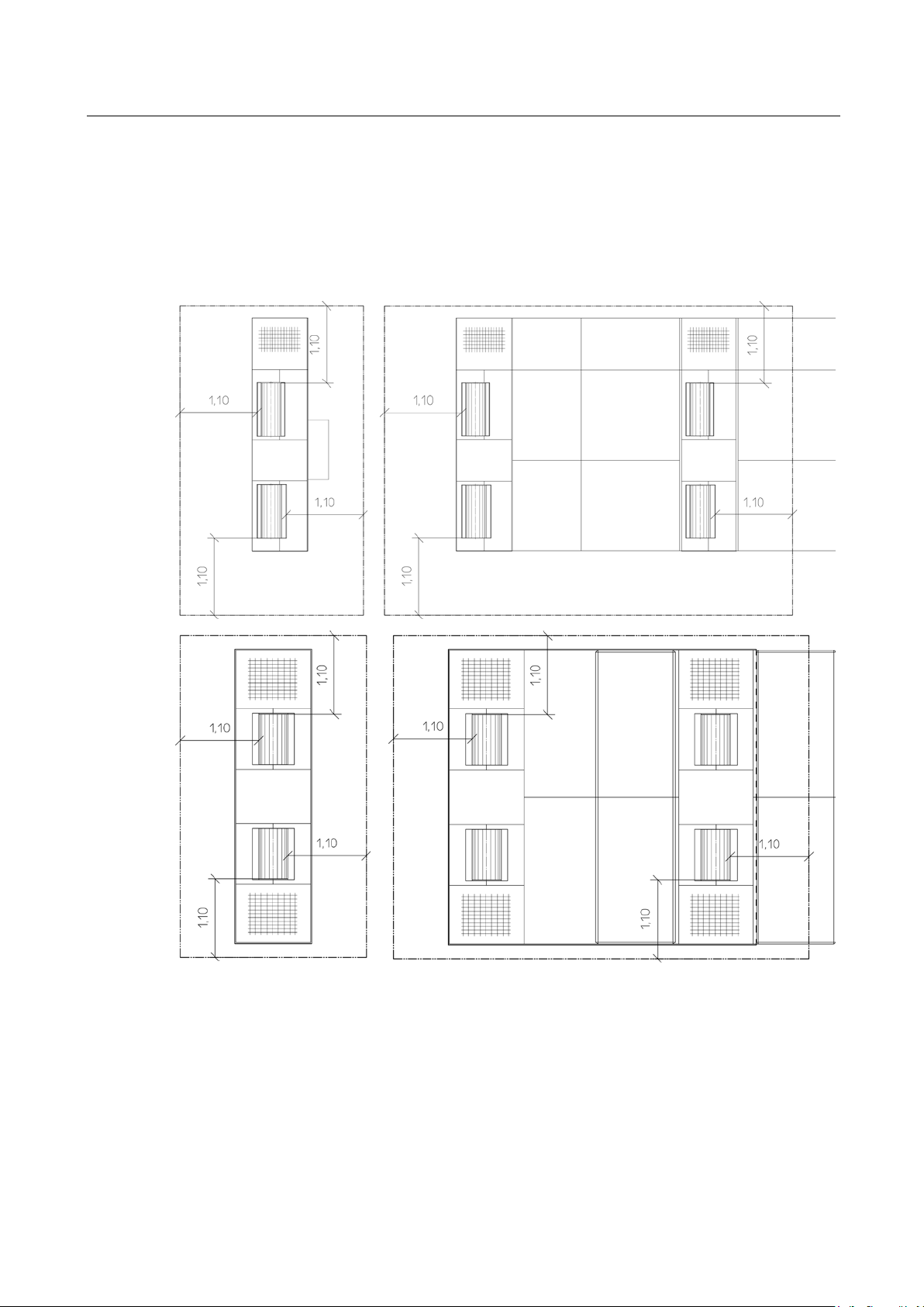
1.7
Danger Zone
1.8
Safety Information about Tires
Pos: 22 /Technische Dokume ntatio n/Alle Geräte/ Übersc hriften/ Überschr iften 1.1/ G/Über sc hrif t 1.1: G efa hrenz one @ 19\ mod_ 126 69381 22676_ 75.do cx @ 782 826 @ 2 @ 1
Pos: 23 /Techn ische Dok ument atio n/Le istun gsmess tec hnik/ - Arc hiv -/00 L PS Alle/ Inhalte/ Inhalt: Gefahr enzon e (Text) LPS A lle @ 23\mod_1298391517468_75.docx @ 978993 @ @ 1
During dynamometer operation no persons are allowed to stay in the danger zone. See illustration
Pos: 24 /Techn ische Dok ument atio n/Le istun gsmess tec hnik/ PO WERDYN O/0 5310 1 MS R/BA/I nha lt: 0 531 G efahr enz one ( Bilder ) @ 24\mod_1305641273004_0.docx @ 1007835 @ @ 1
for minimum distance.
MSR 500 MSR 500 4WD
Pos: 25 /Technische Dokument ation/Alle Gerät e/Übersc hriften/Üb erschriften 1. 1/S/Überschrift 1.1: Sicherheitshinweise zu den Reifen @ 13\mod_1234944733138_75.docx @ 343007 @ 2 @ 1
MSR 800 MSR 1000 4WD
Pos: 26 /Techn ische Dok ument atio n/Le istun gsmess tec hnik/ - Arc hiv -/00 L PS Alle/ Inhalte/ Inhalt: Sicher heitsh inweis e zu d en Re ifen LPS @ 13\ mod_1234174659560_75.docx @ 335356 @ @ 1
• Check tire pressure and do a visual check of the tires for any signs of damage.
• To avoid tire damage we recommend that test tires be used during the performance test.
• No vehicles should be tested which have snow tires, racing tires or retreaded tires!
• Pay attention that the fastest permissible speed for the tires is not exceeded!
• Check the alignment weights on the rims to make sure they are tight before testing.
BA053101-en
Page 11

11
1.9
Safety Information about the Eddy Current Brake
1.10
Safety Features
Lockable Main Switch
Pit Safety (optional)
Warning and Information Labels
1.11
Accessories
1.12
What to Do in the Event of an Accident
Pos: 27 /Techn ische Dokume ntat ion/A lle Ger äte/ Übersc hrift en/ Übersc hrifte n 1.1/ S/Übe rsch rift 1. 1: Sich erheit shin weise zur Wir belstromb remse @ 8\mod_ 120 06549 42824 _75.d ocx @ 141 073 @ 2 @ 1
Pos: 28 /Techn ische Dok ument atio n/Le istun gsmess tec hnik/ - Arc hiv -/00 L PS Alle/ Inhalte/ Inhalt: Sicher heitsh inweis e zur Wirbelstr ombrem se @ 8\mod_1200655009969_75.docx @ 141090 @ @ 1
• Pay attention to tire size! No test should be done with tires under 12”!
The eddy current brake can heat up significantly during long lasting usage. The brake rotors may
become red hot.
After a long lasting measurement under load, the eddy current brake should continue to be rotated
without load by the vehicle at a speed of approx. 50 – 80 km/h.
The rotating rotors suck cooled air from the side and throw it radially off. The eddy current brake is
Pos: 29 /Technische Dokument ation/Alle Gerät e/Übersc hriften/Üb erschriften 1. 1/S/Übersc hrift 1. 1: Sicherhe itsei nrichtun gen @ 6\mod _1174 4833 24765_ 75.d ocx @ 77 103 @ 2 @ 1
Pos: 30 /Techn ische Dok ument atio n/Le istun gsmess tec hnik/ - Arc hiv -/00 L PS Alle/ Inhalte/ Inhalt: Sicher heitse inrich tungen ( Text) LPS @ 22\mod _12 905 908 267 77_75.d ocx @ 94 6329 @ @ 1
thereby effectively cooled preventing heat build-up at the rotors damaging the coil insulation.
The safety features must be checked regularly by an authorized service technician. Pay attention to
statutory requirements. The dyno shall not be operated with defective safety features.
Serves as a normal On and Off switch and as an emergency switch. The switch can be protected
against unauthorized usage by locking with a padlock.
Light barrier or infrared movement sensor. Issues audible and visual signals in the event that persons are in the working pit.
Warning and information labels are attached to the dyno. The labels shall not be changed or
removed. Defective warning and information labels must be replaced.
Pos: 31 /Tec hn isch e Do kumentatio n/Alle Geräte/ Überschrift en/Überschr iften 1.1/Z /Überschr ift 1.1: Zubehör @ 7\mod _11 97021 5365 41_75.d ocx @ 13 6790 @ 2 @ 1
Pos: 32 /Technische Dokument ation/Alle Gerät e/Inhalte/ Sicherhe it/Inhalt: Zubeh ör @ 22\mod _128 818 85362 64_ 75.d ocx @ 927028 @ @ 1
The equipment shall be operated only with accessories which have been approved or permitted by
Pos: 33 /Technische Dokume ntatio n/Alle Geräte/ Übersc hriften/ Überschr iften 1.1/V /Übersc hrift 1 .1: Ver halten bei U nfällen @ 19\m od_ 126 7177 2453 37_7 5.docx @ 79460 0 @ 2 @ 1
Pos: 34 /Technische Dokument ation/Alle Gerät e/Inhalte/ Sicherhe it/Inhalt: Verha lten bei Unfälle n @ 34\mod_1381128804654_75.docx @ 1837123 @ @ 1
MAHA.
• The injured person is to be removed from the danger area. Find out where dressing and band-
ages are kept. Seek first-aid.
• Provide first-aid (stop bleeding, immobilise injured limbs), report the accident and seal off the
accident site.
• Immediately report any accident to your supervisor. Make sure a record is kept of every occa-
sion first-aid is provided, e.g. in an accident book.
Pos: 35 /-----For ma t-----/MA N UEL LER UMB RUC H Se ite num br uch @ 0\m od_1134403577687_0.docx @ 1277 @ @ 1
• Remain calm and answer any questions that may arise.
BA053101-en
Page 12

12
2
Description
2.1
General Information
RPM module
Environmental module
Analog module
OBD module
Pressure/Temperature module
Pos: 36 /Tec hn ische Dokum entation/ Alle Geräte/Üb erschriften/ Überschri ften 1/B/Üb erschrift 1: Beschr eibung @ 6\mod_1174482271453_75.docx @ 76889 @ 1 @ 1
Pos: 37 /Technische Dokument ation/Alle Gerät e/Übersc hriften/Üb erschriften 1. 1/A/Übersc hrift 1.1: Allgem eines @ 6\mod_1182865005781_75.docx @ 97736 @ 2 @ 1
Pos: 38 /Techn ische Dok ument atio n/Le istun gsmess tec hnik/ PO WERDYN O/0 5310 1 MS R/BA/I nha lt: 0 531 Bes chr eibun g Al lgem eines @ 14\mod_1241595173293_75.docx @ 371141 @ @ 1
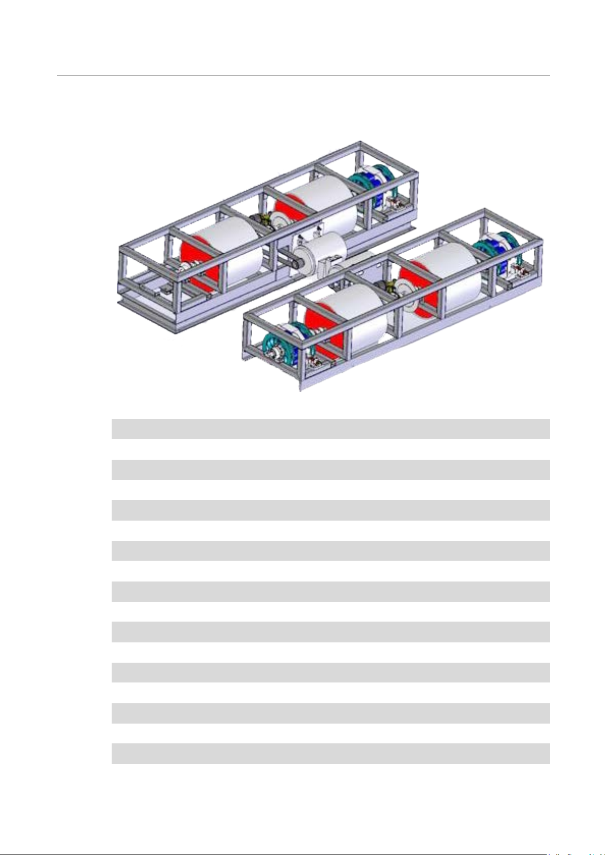
The single roller dynamometer MSR consists of:
• A communication desk with PC, monitor, keyboard and wheel mouse (depending on ver-
sion)
• A remote control
• One or two roller sets
Optionally available are:
• A cooling air fan which is connected to the communication desk and is operated via the radio
remote control.
• An interface box via which the following modules can be connected:
Acquisition of engine RPM via Trigger tongs (Otto engine), Piezo clamp sensor (Diesel engine),
TDC-sensor (manufacturer-specific, upon request), Diagnostic plug (manufacturer-specific, upon
request), Oil temperature probe (up to max. 180°C) and much more.
Acquisition of ambient temperature, intake air temperature, air pressure and humidity, fuel
temperature
Acquisition of analog signals
Aquisition of OBD data
Recording of 2 temperatures and 2 pressures each
• To determine performance data of DIN 70020, EWG 80/1269, ISO 1585, SAE J1349 or JIS
D1001 a barometer and a humidity sensor are installed in the interface box (Graphic package is
(*)
prerequisite)
.
• MAHA emission testers, gasoline (MGT5) and diesel (MDO2 and MDO2 LON) which can be
connected to the dyno
• DIN A4 ink jet printer, color
• Fuel consumption device for gasoline and diesel engines. (Krupp/AIC)
• Analog output card to process measured variables as analog signal
(e.g. display of issued variables on an external analog instrument
(*) These options are not connected to the interface box but separately on the dyno.
Pos: 39 /-----For ma t-----/MA N UEL LER UMB RUC H Se ite num br uch @ 0\m od_1134403577687_0.docx @ 1277 @ @ 1
(*)
.
(*)
(*)
(*)
).
BA053101-en
Page 13
13
2.2
Specifications
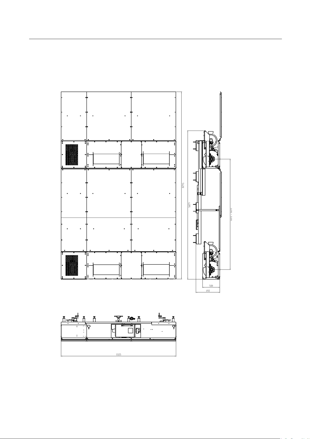
2.2.1
Dimensions
MSR 500
Pos: 40 /Technische Dokument ation/Alle Gerät e/Übersc hriften/Üb erschriften 1. 1/T/Übers chrift 1.1: Technis che Daten @ 7\mod _1 184075526343_75.docx @ 99711 @ 2 @ 1
Pos: 41 /Technische Dokument ation/Alle Gerät e/Übersc hriften/Üb erschriften 1. 1.1/A/Übers chrift 1.1.1 : Abmessunge n @ 14\mod_1241595523910_75.docx @ 371167 @ 3 @ 1
Pos: 42 /Technische Dokume ntatio n/Leistungsmesstechnik/POWERDYNO/053101 MSR/BA/Inhalt: 0531 Abmessungen (Bilder) MSR 500 @ 23\mod_12983 909 220 89_0.d ocx @ 978 971 @ @ 1
Pos: 43 /Tec hn isch e Dokumentation/Leistungsmesstechnik/POWERDYNO/053101 MSR/BA/Inhalt: 0531 Abmessungen (Bilder) MSR 1000 @ 14\mod_1241595624149_0.docx @ 371193 @ @ 1
BA053101-en
Page 14
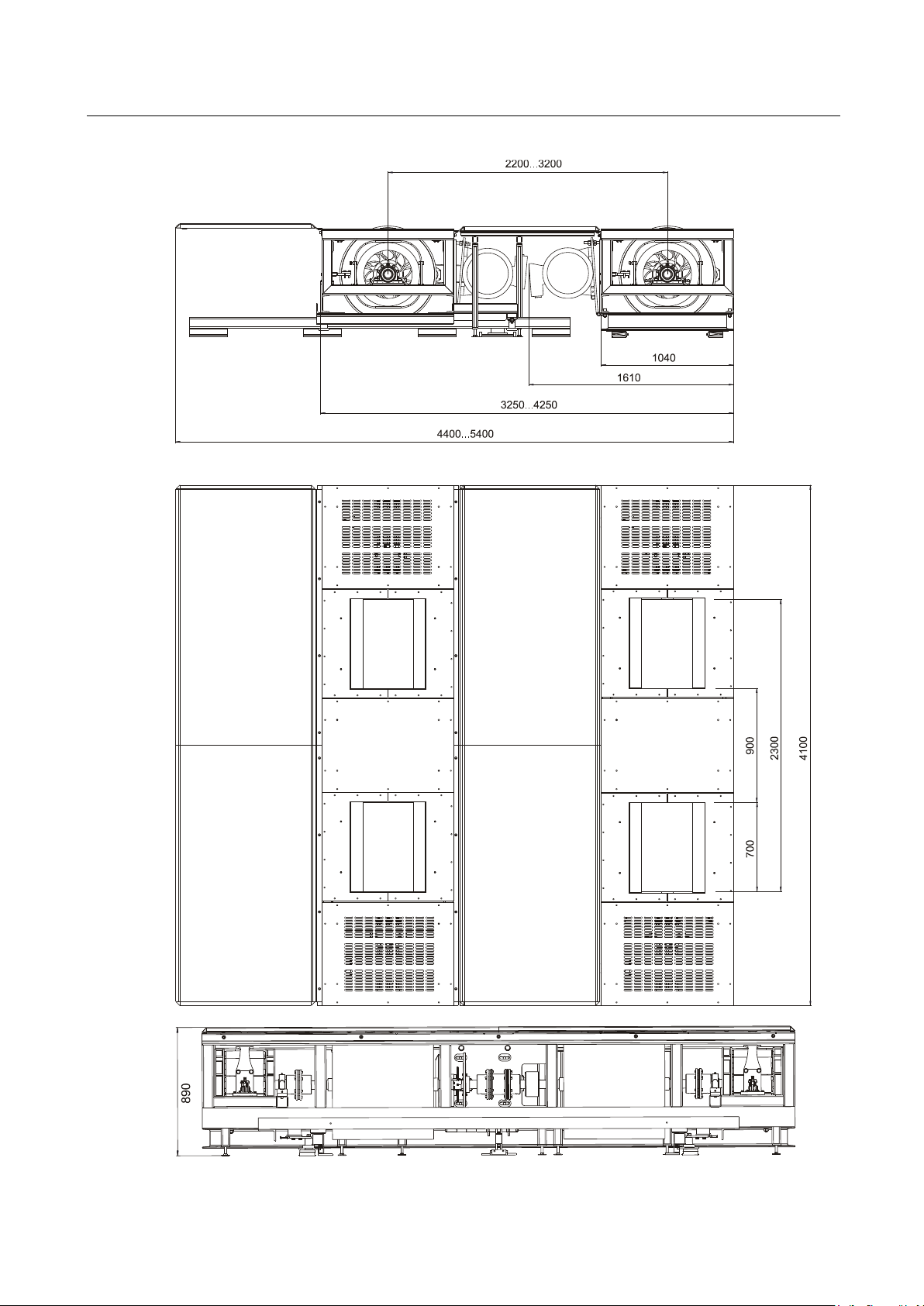
14
MSR 1000
Pos: 44 /Technische Dokument ation/Alle Gerät e/Übersc hriften/Üb erschriften 1. 1.1/K/Über schrift 1. 1.1: Komm un ika tions pu lt @ 13\m od_1 23417 52964 30_7 5.docx @ 3354 86 @ 3 @ 1
BA053101-en
Page 15
15
2.2.2
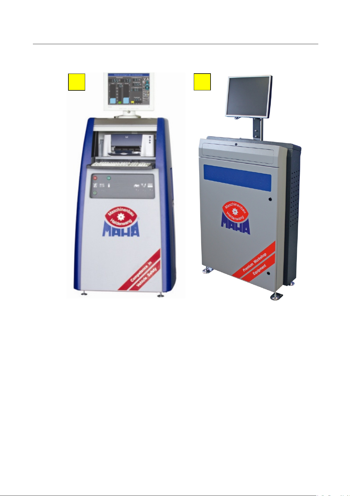
Communication Desk
Pos: 45 /Techn ische Dok ument atio n/Le istun gsmess tec hnik/ PO WERDYN O/0 5310 1 MS R/BA/I nha lt: 0 531 K ommun ika tions pult ( Bild er) @ 23\mod_1296722871974_0.docx @ 969333 @ @ 1
A
B
Pos: 46 /Techn ische Dok ument atio n/Le istun gsmess tec hnik/ PO WERDYNO/053101 MSR/BA/Inhalt: 0531 Kommunikationspult (Text) @ 23\mod_1297151385424_75.docx @ 971753 @ @ 1
Communication desk, Version A .................................................................... 670 x 1400 x 800 mm
Pos: 47 /-----For mat -----/MAN UE LLE R UM BR UCH Se iten umb ruc h @ 0\mod_1134403577687_0.docx @ 1277 @ @ 1
Communication desk, Version B (available from March 2011) ........................ 350 x 1230 x 860 mm
BA053101-en
Page 16
16
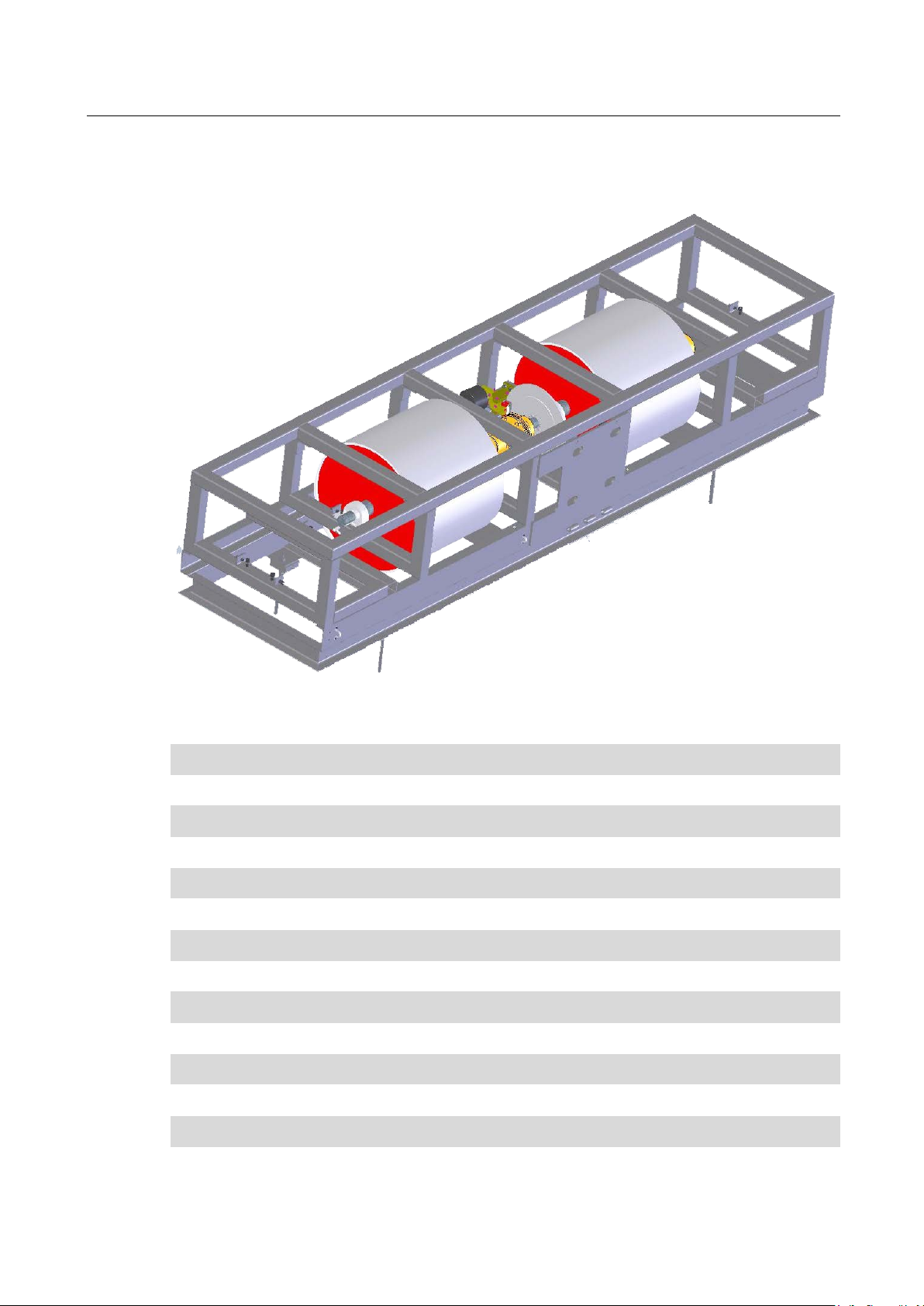
2.2.3
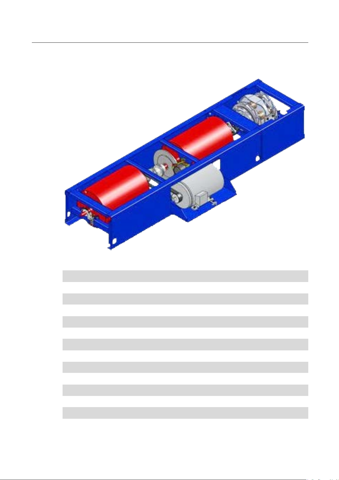
MSR 500/1
1-Axle Roller Set with 1 Eddy Current Brake and 1 Electric Motor
Pos: 48 /Technische Dokume ntatio n/Alle Geräte/ Übersc hriften/ Überschr iften 1.1. 1/M/Über schrift 1.1.1: MSR 5 00/1 @ 24\m od_13 05615 9950 73_0.d ocx @ 1 00740 1 @ 3 @ 1
Pos: 49 /Tec hn isch e Do kum ent atio n/Le ist un gsmes s techn ik/ PO WER DYNO /05 310 1 MS R/B A/In ha lt: 0 531 MSR 5 00/1 ( Bi ld) @ 23\ mod_1296463645669_0.docx @ 968263 @ @ 1
Pos: 50 /Techn ische Dok ument atio n/Le istun gsmess tec hnik/ PO WERDYN O/0 5310 1 MS R/BA /In ha lt: 0 531 MSR 500/ 1 ( Tex t) @ 22\m od_1295432174832_75.docx @ 963400 @ @ 1
Roller diameter 504 mm / 20"
Rolling circumference 1583 mm
Roller length 750 mm
Track width (min….max.) 700…2200 mm
Roller wall thickness 12 mm
Total weight of Roller set 1630 kg
Mech. inertia weight approx. 280 kg
Permissible axle load 2500 kg
Maximum speed 300 km/h
Motor power 22 kW
Wheel power stat. / dyn. 260 / 1000 kW
Const. tractive force 7000 N
Fuse with / without drive 63 / 16 A
Supply voltage 3 x 400 + N + PE
Pos: 51 /Technische Dokume ntatio n/Alle Geräte/ Übersc hriften/ Überschr iften 1.1. 1/M/Über schrift 1.1.1: MSR 5 00/2 @ 24\m od_13 05616 1336 11_0.d ocx @ 1 00743 1 @ 3 @ 1
BA053101-en
Page 17
17
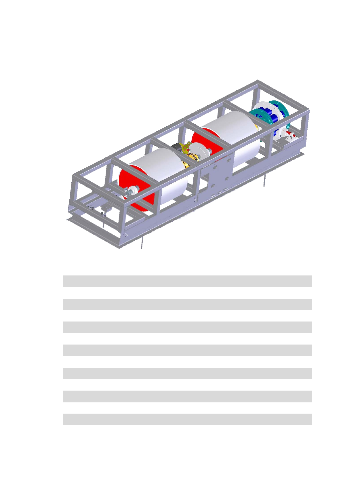
2.2.4
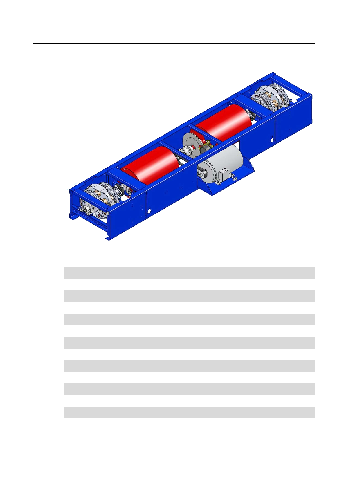
MSR 500/2
1-Axle Roller Set with 2 Eddy Current Brakes and 1 Electric Motor
Pos: 52 /Tec hn isch e Do kum ent atio n/Le ist un gsmes s techn ik/ PO WER DYNO /05 310 1 MS R/B A/In ha lt: 0 531 MSR 5 00/2 ( Bi ld) @ 23\ mod_1296464800590_0.docx @ 968323 @ @ 1
Pos: 53 /Techn ische Dok ument atio n/Le istun gsmess tec hnik/ PO WERDYN O/0 5310 1 MS R/BA/ In halt: 0 531 MSR 500/ 2 ( Tex t) @ 22\m od_1295432706059_75.docx @ 963460 @ @ 1
Roller diameter 504 mm / 20"
Rolling circumference 1583 mm
Roller length 750 mm
Track width (min….max.) 700…2200 mm
Roller wall thickness 12 mm
Total weight of Roller set 1940 kg
Mech. inertia weight approx. 305 kg
Permissible axle load 2500 kg
Maximum speed 300 km/h
Motor power 22 kW
Wheel power stat. / dyn. approx. 520 / 2000 kW (Peak)
Tractive force approx. 14000 N
Fuse with / without drive 63 / 40 A
Supply voltage 3 x 400 + N + PE
Pos: 54 /-----For ma t-----/MA N UEL LER UMB RUC H Se ite num br uch @ 0\m od_1134403577687_0.docx @ 1277 @ @ 1
BA053101-en
Page 18
18
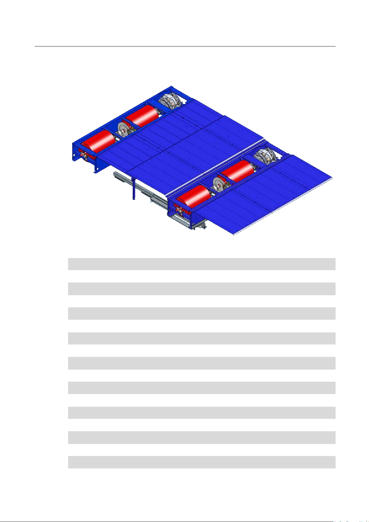
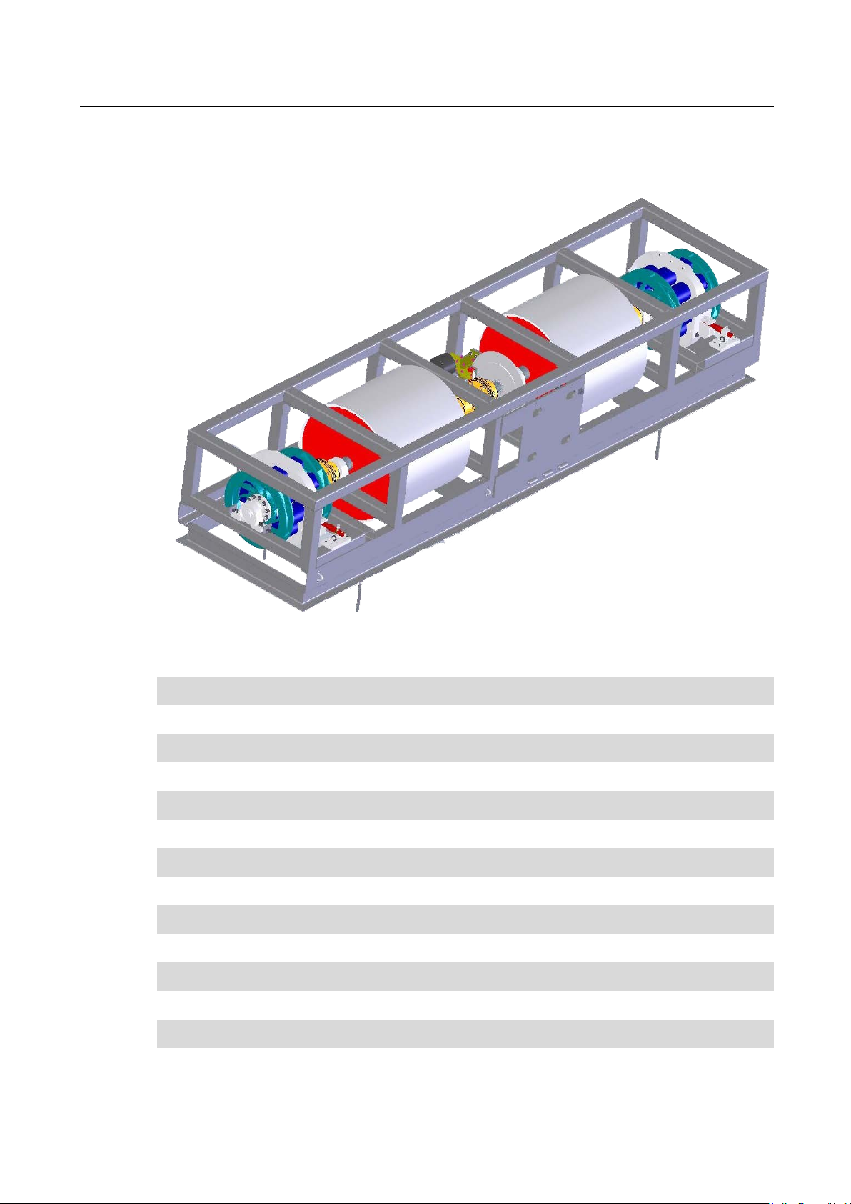
2.2.5
MSR 500/2 4WD
4WD with 1 Eddy Current Brake and 1 Electric Motor per Axle
Pos: 55 /Technische Dokume ntatio n/Alle Geräte/ Übersc hriften/ Überschr iften 1.1. 1/M/Über schrift 1.1.1: MSR 5 00/2 4WD @ 24\mod_1305616199956_0.docx @ 1007461 @ 3 @ 1
Pos: 56 /Tec hn isch e Do kum ent atio n/Le ist un gsmes s techn ik/ PO WER DYNO /05 310 1 MS R/B A/In ha lt: 0 531 MSR 5 00/2 4W D (B ild) @ 23\m od_1296464625288_0.docx @ 968293 @ @ 1
Pos: 57 /Tec hn isch e Do kum ent atio n/Le ist un gsmes s techn ik/ PO WER DYNO /05 310 1 MS R/B A/In ha lt: 0 531 MSR 5 00/2 4W D (Tex t) @ 22\mod_1295435416655_75.docx @ 963520 @ @ 1
Roller diameter 504 mm / 20"
Rolling circumference 1583 mm
Roller length 750 mm
Track width (min….max.) 700…2200 mm
Roller wall thickness 12 mm
Total weight of Roller set 4130 kg
Mech. inertia weight 2 x 280 kg
Permissible axle load 2500 kg
Maximum speed 300 km/h
Maximum speed of a tracked, non-driven axle approx. 200 km/h
Motor power 2 x 22 kW
Wheel power Front axle stat. / dyn. 260 / 1000 kW (Peak)
Wheel power Rear axle stat. / dyn. 260 / 1000 kW (Peak)
Tractive force Front axle approx. 7000 N
Tractive force Front axle approx. 7000 N
Fuse 63 A
Supply voltage 3 x 400 + N + PE
Pos: 58 /Technische Dokume ntatio n/Alle Geräte/ Übersc hriften/ Überschr iften 1.1. 1/M/Über schrift 1.1.1: MSR 500/3 4WD @ 24\mod_1305616255864_0.docx @ 1007491 @ 3 @ 1
BA053101-en
Page 19
19
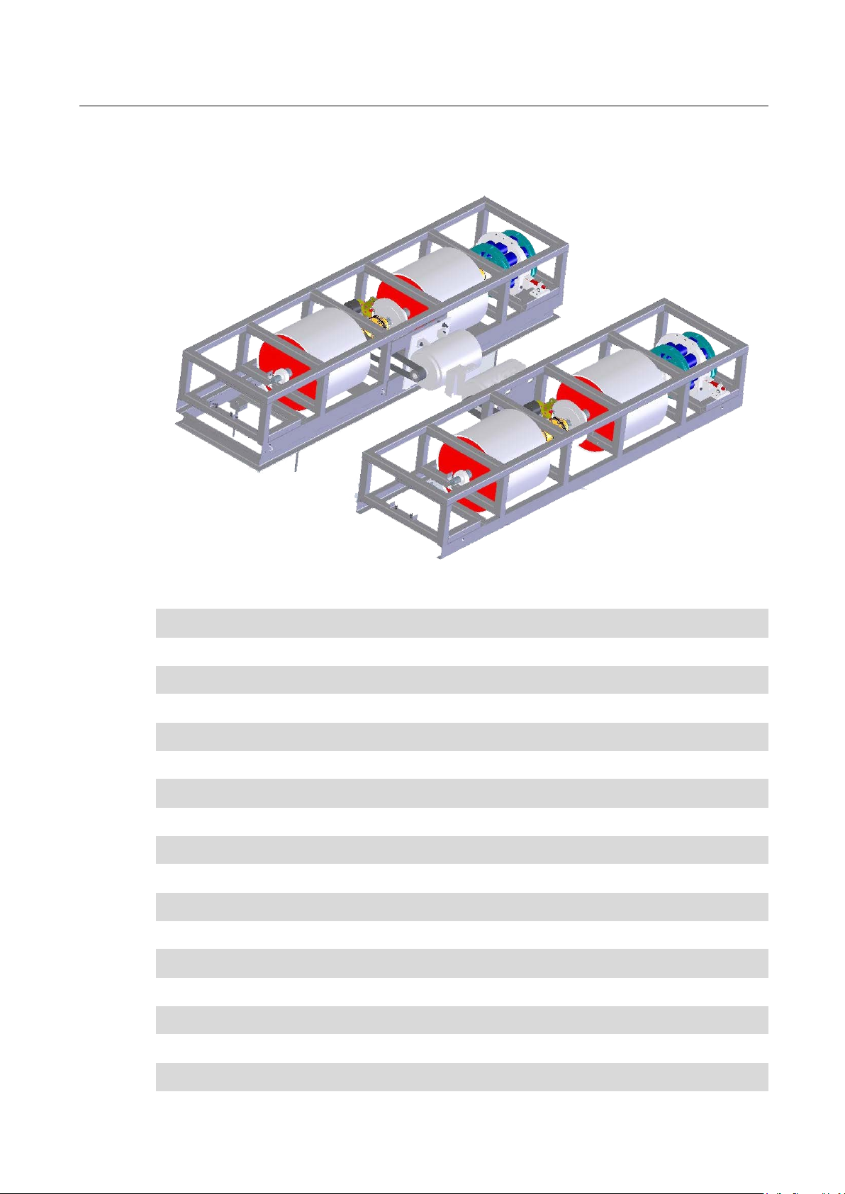
2.2.6
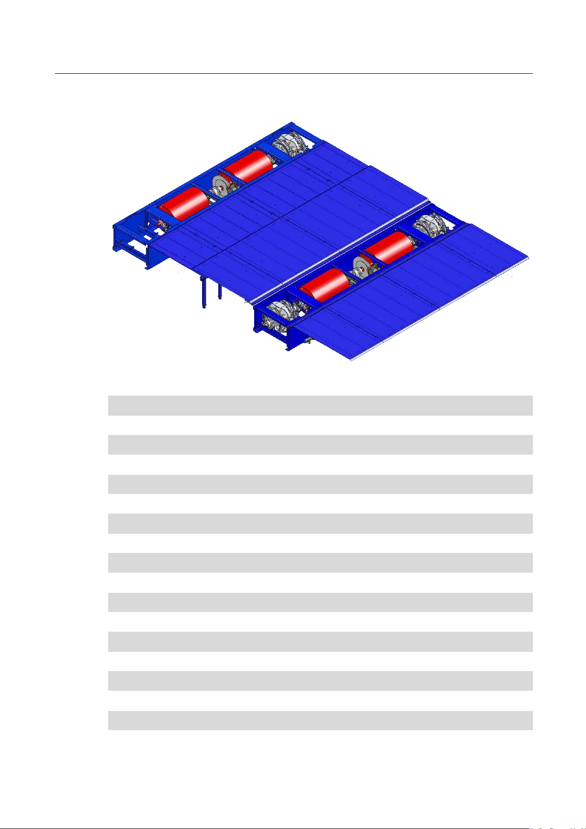
MSR 500/3 4WD
4WD with 1 Eddy Current Brake FA, 2 Eddy Current Brakes RA, 1 Electric Motor per Axle
Pos: 59 /Tec hn isch e Do kum ent atio n/Le ist un gsmes s techn ik/ PO WER DYNO /05 310 1 MS R/B A/In ha lt: 0 531 MSR 5 00/3 4W D (B ild) @ 23\mod_1296464996919_0.docx @ 968353 @ @ 1
Pos: 60 /Tec hn isch e Do kum ent atio n/Le ist un gsmes s techn ik/ PO WER DYNO /05 310 1 MS R/B A/In ha lt: 0 531 MSR 5 00/3 4W D (Tex t) @ 22\mod_1295435803655_75.docx @ 963580 @ @ 1
Roller diameter 504 mm / 20"
Rolling circumference 1583 mm
Roller length 750 mm
Track width (min….max.) 700…2200 mm
Roller wall thickness 12 mm
Total weight of Roller set 4395 kg
Mech. inertia weight 1 x 280 kg / 1 x 305 kg
Permissible axle load 2500 kg
Maximum speed 300 km/h
Maximum speed of a tracked, non-driven axle approx. 200 km/h
Motor power 2 x 22 kW
Wheel power Front axle stat. / dyn. 260 / 1000 kW (Peak)
Wheel power Rear axle stat. / dyn. 520 / 1000 kW (Peak)
Tractive force Front axle approx. 7000 N
Tractive force Front axle approx. 14000 N
Fuse 63 A
Supply voltage 3 x 400 + N + PE
Pos: 61 /-----For ma t-----/MA N UEL LER UMB RUC H Se ite num br uch @ 0\m od_1134403577687_0.docx @ 1277 @ @ 1
BA053101-en
Page 20
20
2.2.7
MSR 800
1-Axle Roller Set
Pos: 62 /Technische Dokume ntatio n/Alle Geräte/ Übersc hriften/ Überschr iften 1.1. 1/M/Über schrift 1.1.1: MSR 8 00 @ 24\mod_1306494127905_0.docx @ 1013813 @ 3 @ 1
Pos: 63 /Technische Dokumentation/Leistungsmesstechnik/POWERDYNO/053101 MSR/BA/Inhalt: 0531 MSR 800 (Bild) @ 23\mod_1298447556531_0.docx @ 9 790 71 @ @ 1
Pos: 64 /Technische Dokumentation/Leistungsmesstechnik/POWERDYNO/053101 MSR/BA/Inhalt: 0531 MSR 800 (Text) @ 14\mod_1241597479700_75.docx @ 371613 @ @ 1
Roller diameter 762 mm / 30"
Rolling circumference 2393 mm
Roller length 700 mm
Track width (min….max.) 900…2300 mm
Roller wall thickness 20 mm
Total weight of Roller set 1910 kg
Mech. inertia weight approx. 700 kg
Permissible axle load 2500 kg
Maximum speed > 300 km/h
Wheel power approx. 660 kW
Const. tractive force not available
Fuse 16 A
Pos: 65 /-----For ma t-----/MA N UEL LER UMB RUC H Se ite num br uch @ 0\m od_1134403577687_0.docx @ 1277 @ @ 1
BA053101-en
Supply voltage 230 V + N + PE
Page 21
21
2.2.8
MSR 830
1-Axle Roller Set with 1 Eddy Current Brake
Pos: 66 /Technische Dokume ntatio n/Alle Geräte/ Übersc hriften/ Überschr iften 1.1. 1/M/Über schrift 1.1.1: MSR 8 30 @ 24\mod_1305616305111_0.docx @ 1007521 @ 3 @ 1
Pos: 67 /Technische Dokumentation/Leistungsmesstechnik/POWERDYNO/053101 MSR/BA/Inhalt: 0531 MSR 830 (Bild) @ 23\mod_12984482086 73_0.d ocx @ 979 137 @ @ 1
Pos: 68 /Technische Dokumentation/Leistungsmesstechnik/POWERDYNO/053101 MSR/BA/Inhalt: 0531 MSR 830 (Text) @ 14\mod_1241597837603_75.docx @ 371639 @ @ 1
Roller diameter 762 mm / 30"
Rolling circumference 2393 mm
Roller length 700 mm
Track width (min….max.) 900…2300 mm
Roller wall thickness 20 mm
Total weight of Roller set 2270 kg
Mech. inertia weight approx. 700 kg
Permissible axle load 2500 kg
Maximum speed > 300 km/h
Wheel power approx. 700 kW (Peak)
Tractive force approx. 8600 N
Fuse 20 A
Supply voltage 3 x 400 V + N + PE
Pos: 69 /-----For ma t-----/MA N UEL LER UMB RUC H Se ite num br uch @ 0\m od_1134403577687_0.docx @ 1277 @ @ 1
BA053101-en
Page 22
22
2.2.9
MSR 850
1-Axle Roller Set with 2 Eddy Current Brakes
Pos: 70 /Tec hn isch e Do kumentatio n/Alle Geräte/ Überschrift en/Überschr iften 1.1. 1/M/Überschr ift 1.1.1: MSR 85 0 @ 24\mod_1306494212398_0.docx @ 1013843 @ 3 @ 1
Pos: 71 /Technische Dokumentation/Leistungsmesstechnik/POWERDYNO/053101 MSR/BA/Inhalt: 0531 MSR 850 (Bild) @ 23\mod_12984483036 66_ 0.d ocx @ 9 791 62 @ @ 1
Pos: 72 /Technische Dokumentation/Leistungsmesstechnik/POWERDYNO/053101 MSR/BA/Inhalt: 0531 MSR 850 (Text) @ 14\mod_1241598845809_75.docx @ 371695 @ @ 1
Roller diameter 762 mm / 30"
Rolling circumference 2393 mm
Roller length 700 mm
Track width (min….max.) 900…2300 mm
Roller wall thickness 20 mm
Total weight of Roller set 2630 kg
Mech. inertia weight approx. 750 kg
Permissible axle load 2500 kg
Maximum speed > 300 km/h
Wheel power approx. 1400 kW (Peak)
Tractive force approx. 17200 N
Fuse 40 A
Supply voltage 3 x 400 V + N + PE
Pos: 73 /-----For ma t-----/MA N UEL LER UMB RUC H Se ite num br uch @ 0\m od_1134403577687_0.docx @ 1277 @ @ 1
BA053101-en
Page 23
23
2.2.10
MSR 1000
4WD with 1 Eddy Current Brake and 1 E-Machine per Axle
Pos: 74 /Technisch e Dok ument ation/Al le Gerät e/Über schrift en/Über schri ften 1. 1.1/M/ Überschr ift 1 .1.1: MSR 10 00 @ 24\ mod_1306493890113_0.docx @ 1013753 @ 3 @ 1
Pos: 75 /Techn ische Dok ument atio n/Le istun gsmess tec hnik/ PO WERDYN O/0 5310 1 MS R/BA/I nha lt: 0531 MSR 1000 (Bild) @ 23\mod_1298448477424_0.docx @ 979192 @ @ 1
Pos: 76 /Technische Dokumentation/Leistungsmesstechnik/POWERDYNO/053101 MSR/BA/Inhalt: 0531 MSR 1000 (Text) @ 14\mod_1241599234153_75.docx @ 371747 @ @ 1
Roller diameter 762 mm / 30"
Rolling circumference 2393 mm
Roller length 700 mm
Track width (min….max.) 900…2300 mm
Roller wall thickness 20 mm
Total weight of Roller set 5610 kg
Mech. inertia weight 2 x 700 kg
Permissible axle load 2500 kg
Maximum speed > 300 km/h
Maximum speed of a tracked, non-driven axle approx. 200 km/h
Motor power 2 x 30 kW
Wheel power Front axle approx. 700 kW (Peak)
Wheel power Rear axle approx. 700 kW (Peak)
Tractive force Front axle approx. 8600 N
Tractive force Rear axle approx. 8600 N
Fuse 63 A
Supply voltage 3 x 400 V
Pos: 77 /-----For ma t-----/MA N UEL LER UMB RUC H Se ite num br uch @ 0\m od_1134403577687_0.docx @ 1277 @ @ 1
BA053101-en
Page 24
24
2.2.11
MSR 1050
4WD with 1 Eddy Current Brake FA, 2 Eddy Current Brakes RA, 1 Electric Motor per Axle
Pos: 78 /Technische Dokume ntatio n/Alle Geräte/ Übers ch rift en/ Über schr ift en 1.1. 1/M /Üb ersc hr ift 1 .1. 1: M SR 1 050 @ 2 4\mod_1306494009976_0.docx @ 1013783 @ 3 @ 1
Pos: 79 /Technische Dokumentation/Leistungsmesstechnik/POWERDYNO/053101 MSR/BA/Inhalt: 0531 MSR 1050 (Bild) @ 23\mod_1298448681304_0.docx @ 979222 @ @ 1
Pos: 80 /Technische Dokumentation/Leistungsmesstechnik/POWERDYNO/053101 MSR/BA/Inhalt: 0531 MSR 1050 (Text) @ 14\mod_1241599445142_75.docx @ 371773 @ @ 1
Roller diameter 762 mm / 30"
Rolling circumference 2393 mm
Roller length 700 mm
Track width (min….max.) 900…2300 mm
Roller wall thickness 20 mm
Total weight of Roller set 5970 kg
Mech. inertia weight 1 x approx. 700 kg / 1 x approx. 730 kg
Permissible axle load 2500 kg
Maximum speed > 300 km/h
Maximum speed of a tracked, non-driven axle approx. 200 km/h
Motor power 2 x 30 kW
Wheel power Front axle approx. 700 kW (Peak)
Wheel power Rear axle approx. 1400 kW (Peak)
Tractive force Front axle approx. 8600 N
Tractive force Rear axle approx. 17200 N
Fuse 63 A
Supply voltage 3 x 400 V + N + PE
Pos: 81 /-----For ma t-----/MA N UEL LER UMB RUC H Se ite num br uch @ 0\m od_1134403577687_0.docx @ 1277 @ @ 1
BA053101-en
Page 25
25
2.3
Main Switch
2.4
Controls and Indicators
A
D
B
E
C
F
Operating Modes
Position 1: OPERATI-
ON
Position 0: CALIBRA-
TION
Position 2:
SETUP
Pos: 82 /Technische Dok umentatio n/Alle Geräte/ Überschrift en/Überschr iften 1.1/H /Überschr ift 1.1: Hauptschal ter @ 6\mod_ 11775 92858 312_ 75.do cx @ 906 35 @ 2 @ 1
Pos: 83 /Technische Dokume ntatio n/Alle Geräte/ Inhalte/ Info!/I nhalt: I nfo - Hauptschalter @ 23\mod_1298624423518_75.docx @ 979863 @ @ 1
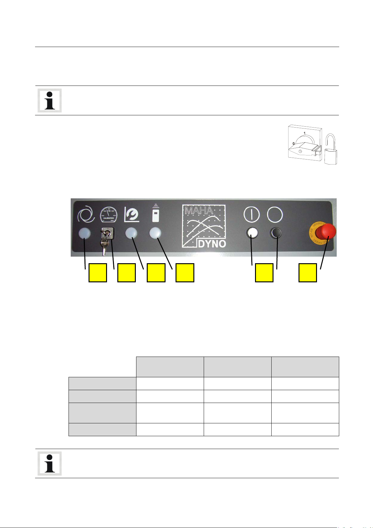
The main switch is located at the side wall of the communication desk.
Pos: 84 /Technische Dokume ntatio n/Alle Geräte/ Inhalte/ Inhal t: Haupts chalt er v1 - A lle Geräte @ 23\mod_1298376098685_75.docx @ 978845 @ @ 1
• Main switch in position 0: Power supply OFF
• Main switch in position 1: Power supply ON
• When in position 0, the main switch can be protected against tampering
by means of a padlock.
Pos: 85 /Technische Dokument ation/Alle Gerät e/Übersc hriften/Üb erschriften 1. 1/B/Übers chrift 1.1: Bedien - und Anz eigeelemen te @ 23\mod_ 12962 20301 443_ 75.do cx @ 9681 07 @ 2 @ 1
Pos: 86 /Technische Dokumentation/Leistungsmesstechnik/POWERDYNO/053101 MSR/BA/Inhalt: 0531 Bedien- und Anzeigeelemente (Bild) @ 24\m od_1305638503474_0.docx @ 1007773 @ @ 1
Pos: 87 /-----For ma t-----/MA NUEL LER UM BRUC H Zeile nscha ltun g @ 7\mod_ 1195 1389 65731_ 0.doc x @ 13217 7 @ @ 1
Pos: 88 /-----For ma t-----/MA NUEL LER UM BRUC H Zeile nscha ltun g @ 7\mod_ 1195 1389 65731_ 0.doc x @ 13217 7 @ @ 1
Pos: 89 /Techn ische Dok ument atio n/Le istun gsmesstechnik/POWERDYNO/053101 MSR/BA/Inhalt: 0531 Bedien- und Anzeigeelemente (Text) @ 23\mod_1296549358503_75.docx @ 968523 @ @ 1
Locking Brake ON ON ON
Hydraulic System OFF OFF ON
Power Section of Eddy
Current Brake
Motors/Converters ON OFF (Safety Stop) OFF (Safety Stop)
Operating Mode Selector Switch
Control ON/OFF
EMERGENCY STOP
ON OFF OFF
B C A D E F
OPERATION Indicator Lamp
SETUP Indicator Lamp
REMOTE CONTROL Indicator Lamp
Each time the operating mode is changed, the control is disabled and must be re-enabled using
the Control ON button.
BA053101-en
Page 26
26
Enabling / Disabling the Dynamometer
2.5
Emergency Stop
A
B
ON
1 Main switch ON.
2 Set operating mode selector switch to re-
3 Control ON.
Dyno is ready for operation.
Pos: 90 /Technische Dokume ntatio n/Alle Geräte/ Übersc hriften/ Überschr iften 1.1/N /Überschr ift 1 .1: No t-Ha lt @ 23\mod_1297171316373_75.docx @ 972449 @ 2 @ 1
Pos: 91 /Technische Dokumentation/Leistungsmesstechnik/POWERDYNO/053101 MSR/BA/Inhalt: 0531 Not-Halt (Bild) @ 24\mod_1305639886912_0.docx @ 1007804 @ @ 1
OFF
1 Control OFF.
2 Main switch OFF.
quired position.
Dyno is shut down.
A B
Pos: 92 /Technische Dokumentation/Leistungsmesstechnik/POWERDYNO/053101 MSR/BA/Inhalt: 0531 Not-Halt (Text) @ 2 3\mod_1296551173826_75.docx @ 968643 @ @ 1
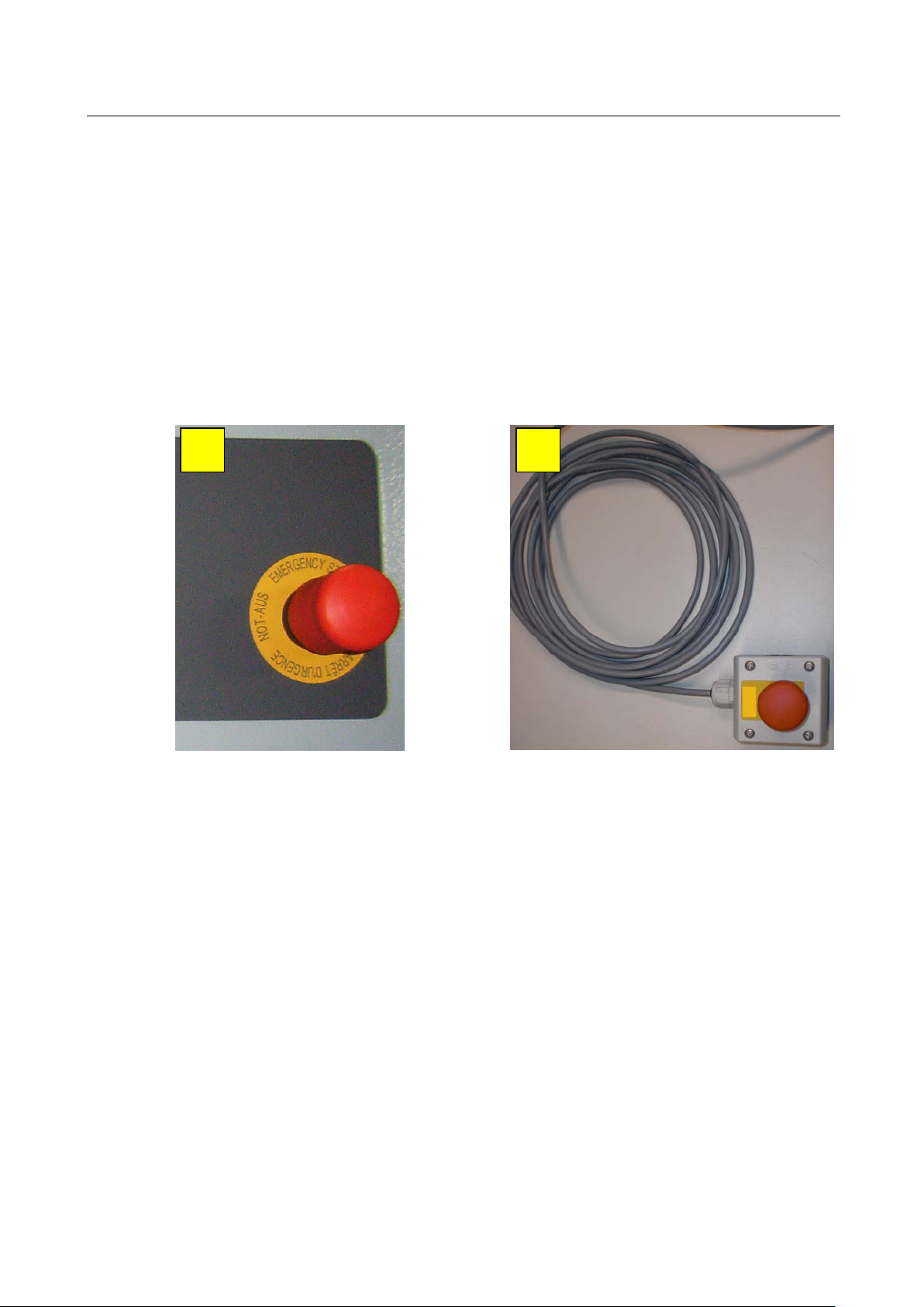
EMERGENCY STOP
at Communication Desk
Push the mushroom button to enable the EMERGENCY STOP:
Motor converters OFF
Power section of eddy current brake OFF
All outputs for hydraulic and pneumatic systems OFF
Pos: 93 /-----For ma t-----/MA N UEL LER UMB RUC H Se ite num br uch @ 0\m od_1134403577687_0.docx @ 1277 @ @ 1
Program must be restarted
Portable EMERGENCY STOP
for Motor-Driven Dynamometers
BA053101-en
Page 27

27
2.6
Remote Control
Remote Control
PC Keyboard
1
2
3
4
5
6
7
8
9
10
11
Pos: 94 /Technische Dokument ation/Alle Gerät e/Übersc hriften/Üb erschriften 1. 1/F/Übers chrift 1.1: Fernbed ienung @ 7\mod_1184152042500_75.docx @ 99994 @ 2 @ 1
Pos: 95 /Tec hn isch e Do kum ent atio n/Le ist un gsmes s techn ik/ PO WER DYNO /05 230 1 L PS 30 00 R100/ BA /In hal t: 0 523 Fern bed ien ung ( Tex t) @ 13\m od_1234179191060_75.docx @ 335824 @ @ 1
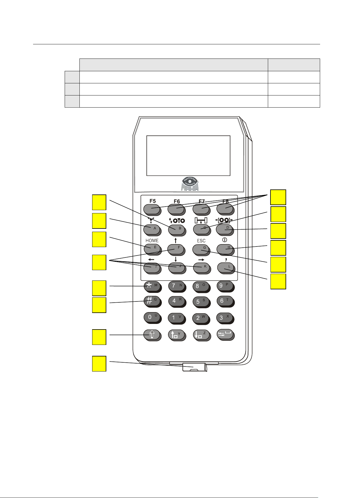
The functions of the program can also be selected via the remote control. The remote control can
be operated directly from the vehicle.
The signal is transmitted by radio. The receiving antenna for the signal is located in the desk.
Should several dynos each with its own remote control be operated in one room, the remote
controls must be set to different channels.
As soon as the remote control is switched on and radio connection to the dyno exists, the green
control lamp will light up permanently on the operation desk. The green control lamp will blink
briefly each time a key is pressed.
When not in use the remote control should always be stored in the re-charging box to avoid a total
discharging of the battery. The re-charging box is equipped with a "re-charge overload protection”.
The re-charging time for a fully discharged battery is about 12 to 14 hours. During the re-charging
procedure the red LED on the re-charging box will light up and "Battery recharging" appears on
the display of the remote control.
To switch on the remote control press the ON key. The remote control has an automatic switch off
(Timeout) which can be variably set. The remote control switches off when no key has been
pressed during this time.
The letters on the remote control can be selected by pressing the SHIFT key. Press again to return
to the normal operation mode. The display "SHIFT" appears in the window when the SHIFT key
has been pressed.
Pos: 96 /Techn ische Dok ument atio n/Le istun gsmess tec hnik/ PO WERDYN O/0 523 01 L PS 300 0 R1 00/ BA/I nha lt: 052 3 Fer nbed ie nun g ( Tabe lle) @ 13\mod_1234943754775_75.docx @ 342981 @ @ 1
The remote control keyboard consists of two pads: Function key pad + Number pad.
Use this key to activate the lifting bar. It can then be operated with the
cursor keys.
F3 + Cursor keys
Switch fan on / off F2
Deletes an entire line
Selection of a menu item
(In combination with the function key F5 and the cursor keys target values can be increased or decreased in some menus.)
Confirmation of inputs Return
Deleting the character before the cursor position
Discarding of inputs
Backspace
Switch over to letter mode
Connection for Pedal force sensor
In some menus special functions can be opened. The key assignments
vary in the different menus. Four boxes with diverse functions are located on the lower screen edge in these menus. These options are select-
F5 to F8
ed with the function keys F5 to F8 on the remote control. If the button
bar has further levels, these can be displayed using the cursor keys.
Use this key to activate the load simulator. It can then be operated with
the cursor keys.
F4 + Cursor keys
Use this key to activate the roller set adjustment. It can then be operated
with the cursor keys.
BA053101-en
Page 28
28
Remote Control
PC Keyboard
12
13
14
Pos: 97 /Tec hn isch e Do kum ent atio n/Le ist un gsmes s techn ik/ PO WER DYNO /05 230 1 L PS 30 00 R100/ BA /In hal t: 0 523 Fern bed ien ung ( Bi ld) @ 13 \mod_1234876860125_0.docx @ 342615 @ @ 1
Switch on remote control
Exit a program part
Input of a comma
1
2
3
4
5
6
7
8
Pos: 98 /-----For ma t-----/MA N UEL LER UMB RUC H Se ite num br uch @ 0\m od_1134403577687_0.docx @ 1277 @ @ 1
9
10
11
12
13
14
BA053101-en
Page 29
29
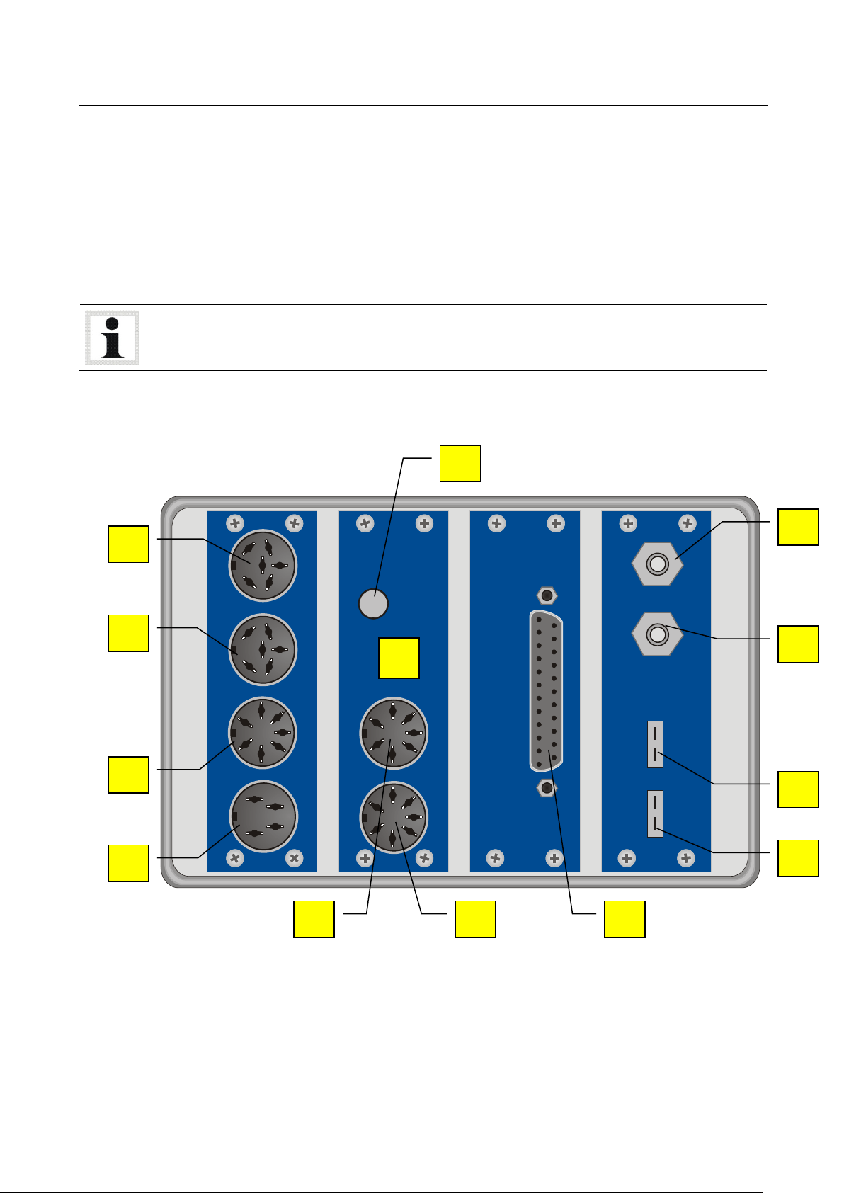
2.7
Description of the Interface Box
DRZ PTH OBD P2T2
A B D C H
E F I M L K J
G
Pos: 99 /Tec hn isch e Dokum entatio n/Alle Geräte/ Überschrift en/Überschr iften 1.1/SC H/Übersc hrift 1.1: Schnittst ellenbox @ 13\mod_1234179450859_75.docx @ 335876 @ 2 @ 1
Pos: 100 /Te ch nisc he D ok umen tati on/ Leis tu ngsm ess tech ni k/PO WE RDYN O/0 523 01 L PS 3 000 R10 0/B A/ Inh alt: 052 3 Sc hni ttst elle nbox ( Text 1) @ 13\m od_1234179543447_75.docx @ 335902 @ @ 1
The Interface Box records engine RPM, environmental data, OBD data, temperature, pressure and
analog signals. This is done via modules. A maximum of 4 modules can be installed in the interface
box.
Additional modules can be installed in a second interface box which is connected parallel and, if
desired, adapted to customer requirements.
As standard equipment, the interface box 1 has an RPM and an environmental module.
Dimensions (H x W x L)
Weight
Pos: 101 /-----F orm at-----/ MAN UEL LE R UMB R UCH Z ei lens cha ltu ng @ 7\mod_1195138965731_0.docx @ 132177 @ @ 1
Pos: 102 /-----F orm at-----/ MAN UEL LE R UMB R UCH Z ei lensc hal tung @ 7\mod_1195138965731_0.docx @ 132177 @ @ 1
Pos: 103 /Te ch nisc he D ok umen tati on/ Leis tu ngsm ess tech ni k/PO WE RDYN O/0 523 01 L PS 3 000 R10 0/B A/ Inh alt: 052 3 Sc hni ttst elle nbox (Bild ) @ 23\mod_1297161281106_0.docx @ 972044 @ @ 1
approx. 120 x 170 x 160 mm
approx. 1.0 kg
Pos: 104 /-----F orm at-----/M ANUELLE R UMBR UCH Seite numbru ch @ 0\mod_1134403577687_0.docx @ 1277 @ @ 1
BA053101-en
Page 30
30
DRZ
A
B
C
D
PTH
E
F
G
H
OBD (Option)
I
P2T2 (Option)
J
K
L
M
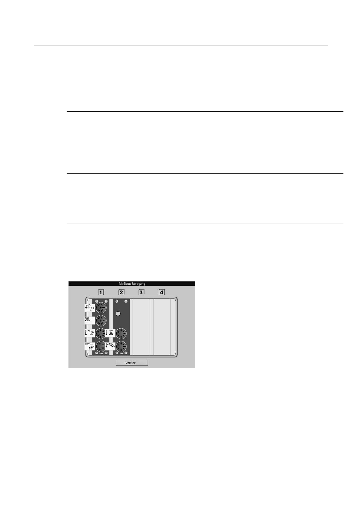
Display the Interface Box Assignment
Pos: 105 /Te ch nisc he D ok umen tati on/ Leis tu ngsm ess tech ni k/PO WE RDYN O/0 523 01 L PS 3 000 R10 0/B A/ Inh alt: 052 3 Sc hni ttst elle nbox (Text 2) @ 13\mod_1234252898101_75.docx @ 336301 @ @ 1
Piezo clamp, TDC sensor Light barrier
Piezo clamp, TDC sensor Light barrier
Oil temperature probe
Trigger tongs
Fuel temperature
Intake air temperature
Atmospheric pressure
Humidity sensor
OBD
Pressure 1
Pressure 2
Temperature 1
Pos: 106 /Te ch nisc he D ok umen tati on/ Leis tu ngsm ess tech ni k/PO WE RDYN O/0 523 01 L PS 3 000 R10 0/B A/ Inh alt: 052 3 Sc hni ttst elle nbox -Be legung ( Text) @ 13\ mod_1234253839295_75.docx @ 336327 @ @ 1
1 The assignment of the interface box appears using the keys <SHIFT> + <F1> .
2 Use <CONTINUE> or <RETURN> to exit this screen.
Pos: 107 /Te ch nisc he D ok umen tati on/ Leis tu ngsm ess tech ni k/PO WE RDYN O/0 523 01 L PS 3 000 R10 0/B A/ Inh alt: 052 3 Sc hni ttst elle nbox -Be legun g (Bild) @ 13\mod_1234254152 771_ 0.docx @ 33635 3 @ @ 1
Pos: 108 /-----F orm at-----/M ANUELLE R UMBR UCH Seite numbru ch @ 0\mod_1134403577687_0.docx @ 1277 @ @ 1
Temperature 2
BA053101-en
Page 31

31
2.7.1
RPM Module (Standard)
Trigger Tongs
(D)
Piezo Clamp
(A)
(B)
Clamp W
Pos: 109 /Technische Dokum entati on/Alle G eräte/ Übers chrifte n/Über schrifte n 1.1.1/ D/Über schrif t 1.1. 1: Drehza hlmod ul (Sta ndard ) @ 1 3\mod _12 34254 5269 44_75.d ocx @ 33 6379 @ 3 @ 1
Pos: 110 /Te ch nisc he D ok umen tati on/ Leis tu ngsm ess tech ni k/PO WE RDYN O/0 523 01 L PS 3 000 R10 0/B A/ Inh alt: 052 3 Dr ehza hlm odu l (S ta ndar d) @ 30\ mod_1363358323459_75.docx @ 1724326 @ @ 1
The RPM module is used to record the RPM and oil temperature (Plug-in card CAN DRZ).
The following RPM sensors/sources can be used:
The RPM signal is picked up at the ignition cable (spark plug or distributor ignition coil) with the
trigger tongs. The trigger tongs should be placed as close as possible to the spark plug and as far
as possible from the next ignition cable. The trigger tongs take up the high voltage signal
inductively which is conducted from the distributor to any random cylinder. The pulse is relayed
from the trigger tongs to the test box where it is converted to an RPM signal.
Attachment:
Position
on the interface box.
Piezo clamp is only used with diesel engines. The piezo clamp consists of a piezo element which
recognizes pressure differences at the lead-in and then converts them into electric pulses. It is
important that the piezo clamp which is used is suitable for only one diameter of the fuel line and
should only be placed at a straight section of the line at any cylinder (attach ground clamp on the
same injection line).
Attachment:
Position
or
on the interface box.
The alternator RPM is ascertained through the clamp W. The number of pulses per rotation at the
alternator (proportional to the crank shaft RPM) should be known or must be determined by an
external measuring device. This is necessary because individual vehicle models have different
transmissions between crank shaft and alternator. The RPM determination at the clamp W is only
used with diesel engine vehicles.
BA053101-en
Page 32

32
TDC Sensor
(A)
(B)
Light Barrier
Notes on adjusting the engine rpm via the light barrier
two
(A)
(B)
Driving Trial
The TDC sensor is always manufacturer-specific, i.e. depending on the vehicle manufacturer the
corresponding diagnostic plug is used for the RPM signal pick up.
The TDC sensor offers an extremely accurate
RPM measurement.
Once f
rot/min
is reached, an RPM of 12000
max
-1
is displayed.
The level must be between 30 mV and 30 V
so that an RPM pulse is recognized
Attachment:
• Position
or
on the interface box.
The light barrier is used when no direct way of determining the RPM at the engine is possible. The
transmission ratio to the engine RPM must be 1:1. If the light barrier is attached to the cardan
shaft, the transmission ratio must be between 0.5 and 2. The light barrier must be positioned in
such a way that via a reflector which is attached either to the vibration absorber, drive belt, or
cardan shaft, the RPM can be picked up free of any interference (no vibration influence etc.).
When making adjustments in the lower rpm range (drive shaft rpm < 800), we recommend using
reflectors in order to double the number of impulses generated.
When doing so, please remember the following:
• The reflectors must be systematically placed around the engine, exactly opposite one another.
Prominent points on the engine housing can be used to position the reflectors.
• When entering the gear ratio you must also double the previous value.
Attachment:
Position
or
on the interface box.
If none of the above mentioned alternatives is available for determining an RPM measurement, a
driving trial can be used to do the same. The RPM is converted from the dyno roller speed.
BA053101-en
Page 33

33
OBD Module
Oil Temperature Probe (Optional)
(C)
2.7.2
Environmental Module (Standard)
Fuel Temperature (Optional)
Intake Air Temperature
Ambient Temperature
At the beginning of a test a pre-determined RPM value must be approached ('Test gear' / Gear
transmission close to 1:1) while in a specific gear. This RPM value will be stored.
During the performance test the software will convert the roller’s current RPM into engine RPM.
(Please note: The calculated RPM will only correspond if the vehicle is driven in the 'test gear'.)
Automatic transmission vehicles without converter lockup cannot use the driving trial method, because the engine RPM deviates due to converter slip.
The RPM is read from the OBD data.
Driving trials should only be done when the engine is warmed up to operational temperature. The
oil temperature meter is used to determine the oil temperature and to monitor it during the testing
procedure.
Oil temperature probe for car and truck, with
variable length (100 to 1500 mm), with plug and
6 m supply line.
Attachment:
Position
Pos: 111 /Te ch nis che Dok ume nta tion /A lle G er äte/ Übe rsc hr ifte n/Üb er schr ifte n 1 .1. 1/U/ Über sc hr ift 1.1. 1: Umwe ltm odu l (S tandard) @ 13\m od_12 34256 46353 0_7 5.docx @ 33649 1 @ 3 @ 1
Pos: 112 /Te ch nisc he D ok umen tati on/ Leis tu ngsm ess tech ni k/PO WE RDYN O/0 523 01 L PS 3 000 R10 0/B A/ Inh alt: 052 3 Um we ltmod ul ( Sta ndard) @ 13\mod_1234256864083_75.docx @ 336517 @ @ 1
on the interface box.
The environomental module is used to record the environmental data (Plug-in card CAN PTH).
• Fuel temperature (Optional)
• Intake air temperature
• Ambient temperature
• Air pressure
• Humidity
The fuel temperature is recorded using the interface box and the fuel consumption device and and
can be used as additional information for the fuel consumption measurement.
The intake air temperature is recorded using the interface box and is used for projection of the
engine performance based on DIN 70020, EWG 80/1269, ISO 1585, SAE J1349 or JIS D1001.
The ambient temperature is recorded using the interface box.
BA053101-en
Page 34

34
Air Pressure
Humidity
2.7.3
OBD Module (Optional)
(OBD)
2.7.4
Pressure/Temperature Module (Optional)
Pressure 1 + 2
Exhaust Gas Temperature
The air pressure is recorded using the interface box and is used for projection of the engine
performance based on DIN 70020, EWG 80/1269, ISO 1585, SAE J1349 or JIS D1001.
The humidity is recorded using the interface box and is used for projection of the engine
performance based on DIN 70020, EWG 80/1269, ISO 1585, SAE J1349 or JIS D1001.
The current air temperature , ambient pressure and relative humidity is included in the calculation
with the given standards (DIN 70020, EWG 80/1269, ISO 1585, SAE J1349 and JIS D1001)
Pos: 113 /Technische Dokum entati on/Alle G eräte/ Übers chrifte n/Über schrifte n 1.1.1/O /Über schr ift 1.1. 1: OBD-M odul (Option) @ 13\mod_1234257204298_75.docx @ 336543 @ 3 @ 1
Pos: 114 /Te ch nisc he D ok umen tati on/Leistungsmesstechnik/POWERDYNO/052301 LPS 3000 R100/BA/Inhalt: 0523 OBD-Modul (Option) (Text) @ 13\mod_1234257277407_75.docx @ 336659 @ @ 1
The OBD module is used for recording the OBD data (Plug-in card CAN OBD Module). This OBD
data is different depending on the vehicle manufacturer.
Attachment:
Pos: 115 /Te ch nisc he D ok umen tati on/ Leis tu ngsm ess tech ni k/PO WE RDYN O/0 523 01 L PS 3 000 R10 0/B A/ Inh alt: 052 3 OBD -Modul (Op tion) (Bild) @ 1 3\mod_ 1234 2583 59352_ 0.docx @ 33668 5 @ @ 1
Pos: 116 /Technische Dokum entati on/Alle G eräte/ Übers chrifte n/Über schrifte n 1.1.1/ D/Über schrif t 1.1. 1: Druck/ Temper aturm odul ( Option) @ 13\m od_1 23425 84321 20_7 5.docx @ 3367 11 @ 3 @ 1
Pos: 117 /Te ch nisc he D ok umen tati on/ Leis tu ngsm ess tech ni k/PO WE RDYN O/0 523 01 L PS 3 000 R10 0/B A/ Inh alt: 052 3 Dr uck/ Tem per atur mod ul ( Op tion) @ 13\mod_1234258485560_75.docx @ 336737 @ @ 1
• Position
on the interface box (see section
The pressure/temperature module is used to record 2 temperatures and 2 pressures (Plug-in card
CAN P2T2).
Pressure 1 +2 is user specific. The test range stretches from– 0.9 to + 4.0 bar and can for example
be used to determine the intake pressure, turbocharger pressure, etc.
The exhaust gas temperature is used as monitor check of the combustion process and to judge its
quality.
The high temperature sensor consists. of a Ni-Cr-Ni thermo element with compensation line.
The measurement range stretches from 0 to 1000 °C.
Pos: 118 /-----F orm at-----/M ANUELLE R UMBR UCH Seite numbru ch @ 0\mod_1134403577687_0.docx @ 1277 @ @ 1
"Description of the Interface Box"
).
BA053101-en
Page 35

35
2.7.5
Analog Input Module (Optional)
2.8
Analog Output Card (Optional)
Pos: 119 /Technische Dokum entati on/Alle G eräte/ Übers chrifte n/Über schrifte n 1.1.1/A /Über schr ift 1.1. 1: Anal ogein gangsm odul (Option) @ 13\mod_1234258646518_75.docx @ 336763 @ 3 @ 1
Pos: 120 /Te ch nisc he D ok umen tati on/ Leis tu ngsm ess tech ni k/PO WE RDYN O/0 523 01 L PS 3 000 R10 0/B A/ Inh alt: 052 3 An alo gein ga ngsm odul (Opti on) (Text) @ 13\m od_1234258712534_75.docx @ 336789 @ @ 1
The analog input module is used to record 4 analog signals (Plug-in card CAN AIN4).
Pos: 121 /Technische Dokum entati on/Leis tungsm esstech nik/POWE R DYNO/0 523 01 LPS 3 000 R10 0/B A/I nhal t: 05 23 A na loge in gangs m odu l (Opt ion ) ( Bild ) @ 13\mod_1234258797503_0.docx @ 336815 @ @ 1
Measurement data from –10 V to +10 V or from –20 mA to +20 mA can be recorded.
Pos: 122 /Technische Dokum entati on/Alle G eräte/ Übers chrifte n/Über schrifte n 1.1/A/ Übers chrift 1.1: A nalog-Au sga ngs karte (Option) @ 13\mod_1234259302517_75.docx @ 336841 @ 2 @ 1
Pos: 123 /Te ch nisc he D ok umen tati on/ Leis tu ngsm ess tech ni k/PO WE RDYN O/0 523 01 L PS 3 000 R10 0/B A/ Inh alt: 052 3 An alo gaus gan gska rte (Option) @ 13\mod_1234259391712_75.docx @ 336867 @ @ 1
The analog output card (Plug-in card LON OUTA) is used for further processing of measured
values as analog signals for an external device (e.g. analog display, digital display).
There are 4 analog outputs available from –10 V to +10 V.
The plug-in card LON OUTA is connected in the communication desk.
Pos: 124 /-----F orm at-----/M ANUELLE R UMBR UCH Seite numbru ch @ 0\mod_1134403577687_0.docx @ 1277 @ @ 1
BA053101-en
Page 36

36
2.9
Measurement Programs
Load Simulation
Measure Engine Power
Extrapolation of the Engine Power (Optional)
Flexibility Test
Speedometer Test
Road Load Adaption (Optional)
Lug-Down Test (Optional)
Pos: 125 /Technische Dokum entati on/Alle G eräte/ Übers chrifte n/Über schrifte n 1.1/M/ Über schrif t 1.1: M esspr ogramm e @ 13\mod_1234259459658_75.docx @ 336893 @ 2 @ 1
Pos: 126 /Te ch nisc he D ok umen tati on/ Leis tu ngsm ess tech ni k/PO WE RDYN O/0 523 01 L PS 3 000 R10 0/B A/ Inh alt: 052 3 Mes spr ogr amm e @ 1 3\mod_1234259499194_75.docx @ 336939 @ @ 1
This dynamometer provides an exact simulation of defined road load conditions.
Fuel consumption measurement and exhaust analysis, as well as serial monitoring of vehicles can
be carried out.
The following operation modes can be selected for conducting the various measurement tasks:
•
The user can pre-select from various load conditions which make possible the determination of
e.g. a specific engine diagnosis or vehicle climbing power. Depending upon need, various load
conditions can be simulated such as constant traction, a constant speed, a constant RPM or a
driving simulation.
•
Use this menu item to determine the vehicle’s engine power (continuous and discrete
measurement).
•
Extrapolation of the engine power based on DIN 70020, EWG 80/1269, ISO 1585, JIS D 1001,
SAE J 1349.
•
The engine flexibility can be checked using this menu item. Once the flexibility test has been called
up the vehicle weight and road load must be entered as in the road load simulation test.
•
The vehicle’s speedometer can be tested using this menu item. The speed can be tested as well.
•
Various dyno coefficients can be determined using this menu item. The iterative coefficient
adaption can be done based on ECE or SAE J2264 standard.
•
Pos: 127 /-----F orm at-----/M ANUELLE R UMBR UCH Seite numbru ch @ 0\mod_1134403577687_0.docx @ 1277 @ @ 1
Use this menu item to do a diesel exhaust measurement under full load.
BA053101-en
Page 37

37
2.10
Calculation Basis
2.10.1
Road Load
m a
v
3,6
P
v
v
3,6
P
v
v
3,6
P
F
ref
Roll
2
ref
Flex
3
ref
2
Air
x
⋅+
⋅
+
⋅
⋅
+
⋅⋅
=
Air resistance power P-Air [kW]
v ) v (v A c 0,5 P
2
0FrontWAir
⋅+⋅⋅⋅⋅=
r
Flex power P-Flex [kW]
v g m P
wFlex
⋅⋅⋅=
m
Pos: 128 /Technische Dokum entati on/Alle G eräte/ Übers chrifte n/Über schrifte n 1.1/ B/Übersc hrif t 1.1: Berechn ungsgr undlagen @ 1 3\mod_ 1234 2599 26127_ 75.do cx @ 3369 95 @ 2 @ 1
Pos: 129 /Technische Dokum entati on/Alle G eräte/ Übers chrifte n/Über schrifte n 1.1.1/ F/Über schrift 1.1.1 : Fahrw iders tände @ 13\mod_1234260532279_75.docx @ 337111 @ 3 @ 1
Pos: 130 /Technische Dokum entati on/Leis tungsm esstech nik/POWE R DYNO/052301 LPS 3000 R100/BA/Inhalt: 0523 Fahrwiderstände @ 13\mod_1234260604469_75.docx @ 337167 @ @ 1
Equation
with
• v
• v Driving speed
• P
• P
• P
• a.m Vehicle mass
The air resistance power is proportional to the surface of
the vehicle front and air resistance coefficient c
with e.g.
• Air density r (rho)
Reference speed for resistance performance values - normally 90 km/h.
ref
Air resistance performance [kW]
air
Flex performance [kW]
flex
Roll resistance performance [kW]
Roll
.
w
= 1.1 kg/m
3
• air resistance coefficient
• Front surface
(VEH-width x Height)
• Driving speed
• Head wind speed
results:
• P
= 0,5 · 1,1 · 0,38 · 2,5 · 252 · 25
air
W
A
Front
v = 90 km/h = 25 m/s
v
0
= 0.38
= 1.7 m · 1.47m = 2.5 m2
= 0 m/s
= 8.164 kW at 90 km/h
c
Flex power or resistance is defined as the power loss
which occurs due to the flexing of the tire on the road
surface and/or roller.
Generally speaking the flex power does not have a relevant influence on the test results due to the
minimal flex resistance coefficient.
BA053101-en
Page 38

38
Roller Resistance Power P-Roll [kW]
v
g
m
P
rRoll
⋅⋅
⋅
=
m
Mass m = Vehicle mass [kg]
[N] a m F ⋅=
2.10.2
Torque
[U/min]
n
9549 [kW] P
M
⋅
=
The rolling resistance power arises from tire and road
surface deformation as a function of speed:
with e.g.
µ
• Roll resistance coefficient of the tires
• Vehicle mass
• Gravitation constant
• Driving speed
= 0.012
r
m = 950 kg
g = 9.81 m/s
2
v = 90 km/h = 25 m/s
the result is:
• P
= 0.012 · 950 · 9.81 · 25
Roll
= 2.79 kW
Since this value only represents a small fraction of the total Road Load it is entered as a fixed
standard value on our dynamometers: for steel belted radial tires approx. 2.5 kW, for winter tires
approx. 3.75 kW.
Setting of the vehicle mass, the aerodynamic drag power and the rolling resistance power is
absolutely necessary for Road Load simulation and stop watch tests, in order to simulate the
vehicle under the correct Road Loads.
This value is needed in order to attain a proportional
traction F via the eddy-current brake from the vehicle
determined acceleration.
Pos: 131 /Te ch nisc he D okumenta tion/Alle Geräte/ Überschr iften/Üb erschriften 1.1 .1/D/Übersc hrift 1.1.1: Drehm oment @ 13\m od_12 34262 2806 68_7 5.docx @ 33719 3 @ 3 @ 1
Pos: 132 /Te ch nisc he D ok umen tati on/ Leis tu ngsm ess tech ni k/PO WE RDYN O/0 523 01 L PS 3 000 R10 0/B A/ Inh alt: 052 3 Dr ehmom ent Form el @ 13\m od_1234262323981_75.docx @ 337219 @ @ 1
Equation
Pos: 133 /-----F orm at-----/M ANUELLE R UMBR UCH Seite numbru ch @ 0\mod_1134403577687_0.docx @ 1277 @ @ 1
BA053101-en
Page 39

39
2.10.3
Extrapolation of the Engine Power with Gasoline Engines
⇒
5,
0
293
[K] T
[mbar]
p
1013
Ka
⋅
=
⇒
[
]
6,0
1,2
298
[K]
T
mbarp
990
Ka
⋅
=
⇒
[ ]
6,0
1,2
298
[K] T
mbarp
990
Ka
⋅
=
⇒
[ ]
6,0
1,2
298
[K] T
mbarp
990
Ka
⋅
=
⇒
[ ]
6,0
1,2
298
[K] T
mbarp
990
Ka
⋅
=
Pos: 134 /Technische Dokum entati on/Alle G eräte/ Übers chrifte n/Über schrifte n 1.1.1/H /Üb erschrif t 1.1. 1: Hoc hrechnu ng der Motor leistun g bei B enzin-M ot oren @ 1 3\mod _123 42624 37293_ 75.d ocx @ 33 7245 @ 3 @ 1
Pos: 135 /Te ch nisc he D ok umen tati on/ Leis tu ngsm ess tech ni k/PO WE RDYN O/0 523 01 L PS 3 000 R10 0/B A/ Inh alt: 052 3 Ho chre ch nung d e r Mot orl eis tun g be i Be nzin- Motor en @ 13\m od_1234262505731_75.docx @ 337271 @ @ 1
• DIN 70020
• EEC 80/1269
• ISO 1585
• SAE J1349
• JIS D1001
with
• Ka correction factor
• p Atmospheric pressure at the dyno in mbar (1 mbar = 0.001 bar)
• T Air temperature at the dyno in Kelvin (0°C = 273 K)
e.g.
• ambient air pressure p = 936 mbar
• ambient temperature T = 17°C = 290K
• based on DIN 70200 the result is: Ka = 1.07671
Pos: 136 /-----F orm at-----/M ANUELLE R UMBR UCH Seite numbru ch @ 0\mod_1134403577687_0.docx @ 1277 @ @ 1
BA053101-en
Page 40

40
2.10.4
Extrapolation of the Engine Power with Diesel Engines (Naturally Aspirated or Supercharged)
⇒
[ ]
5,0
293
[K] T
mbarp
1013
Ka
⋅=
⇒
[ ]
fm
⋅=
7,0
298
[K] T
mbarp
990
Ka
⇒
[ ]
fm
⋅=
7,0
298
[K] T
mbarp
990
Ka
⇒
[ ]
fm
⋅=
7,0
298
[K] T
mbarp
990
Ka
⇒
[
]
fm
⋅=
7,0
298
[K]
T
mbarp
990
Ka
Pos: 137 /Te chnis che Dok umen tation/A lle Ger äte/Üb erschr iften/Üb erschr iften 1 .1.1/H/Üb ers chrift 1.1.1: H ochrech nung d er Mo torleis tung bei Dies el-M otoren (Sa uger bz w. mech . Lad er) @ 1 3\mod _123 42627 21450 _75.d ocx @ 3 37297 @ 3 @ 1
Pos: 138 /Te ch nisc he D ok umen tati on/ Leis tu ngsm ess tech ni k/PO WE RDYN O/0 523 01 L PS 3 000 R10 0/B A/ Inh alt: 052 3 Ho chre ch nung d e r Mot orl eis tu ng b ei D iese l-M otoren ( Sauger b zw. m ech. Lad er) @ 13\mod_1234262821215_75.docx @ 337323 @ @ 1
• DIN 70020
• EEC 80/1269
• ISO 1585
• SAE J1349
• JIS D1001
with
• fm Engine factor (Standard = 0.3)
Pos: 139 /-----F orm at-----/M ANUELLE R UMBR UCH Seite numbru ch @ 0\mod_1134403577687_0.docx @ 1277 @ @ 1
BA053101-en
Page 41

41
2.10.5
Extrapolation of the Engine Power with Turbodiesel Engines
⇒
[ ]
5,0
293
[K] T
mbarp
1013
Ka
⋅=
⇒
[ ]
fm
⋅
=
5,1
0,7
298
[K] T
mbarp
990
Ka
⇒
[ ]
fm
⋅
=
2,1
0,7
298
[K] T
mbarp
990
Ka
⇒
[ ]
fm
⋅
=
5,1
0,7
298
[K] T
mbar
p
990
Ka
⇒
[ ]
fm
⋅
=
5,1
0,7
298
[K] T
mbarp
990
Ka
⇒
[ ]
fm
⋅
=
7,0
0,7
298
[K]
T
mbar
p
990
Ka
Pos: 140 /Technische Dokum entati on/Alle G eräte/ Übers chrifte n/Über schrifte n 1.1.1/H /Üb erschrif t 1.1. 1: Hoc hrechnu ng der Motor leistun g bei T urbodi esel-Mo tore n @ 13\mod_1234267721157_75.docx @ 337349 @ 3 @ 1
Pos: 141 /Te ch nisc he D ok umen tati on/ Leis tu ngsm ess tech ni k/PO WE RDYN O/0 523 01 L PS 3 000 R10 0/B A/ Inh alt: 052 3 Hochr echnun g der Motorl eistung bei T urbodies el-M otor en @ 13\ mod_1234268324182_75.docx @ 337375 @ @ 1
• DIN 70020
• EEC 80/1269
• ISO 1585
• SAE J1349
• JIS D1001
with
fm Engine factor (Standard = 0.3)
The extrapolation formula for Turbodiesel engines in the ISO 1585 only applies to air cooled
charge-air coolers. The following equation applies to water cooled charge-air coolers:
• ISO 1585
(water cooled)
Pos: 142 /-----F orm at-----/M ANUELLE R UMBR UCH Seite numbru ch @ 0\mod_1134403577687_0.docx @ 1277 @ @ 1
BA053101-en
Page 42

42
2.10.6
Calculate Engine Factor fm
652,37 ≤≤
r
q
14,1.036,0 −=
r
q
fm
2,37<
r
q
2,0=fm
65>
r
q
2,
1=
fm
6540
≤≤
r
q
14,1
.036,
0 −=
r
q
fm
40
<
r
q
3,0=fm
65>
r
q
2,1=fm
E
L
P
P
r =
nD
F
q⋅= .120000
nD
F
q⋅= .60000
Pos: 143 /Technische Dokum entati on/Alle G eräte/ Übers chrifte n/Über schrifte n 1.1.1/M /Üb erschr ift 1. 1.1: Mot orfak tor fm be rechne n @ 13\mod_1234268542057_75.docx @ 337401 @ 3 @ 1
Pos: 144 /Te ch nisc he D ok umen tati on/ Leis tu ngsm ess tech ni k/PO WE RDYN O/0 523 01 L PS 3 000 R10 0/B A/ Inh alt: 052 3 M otor fakt or fm b erech nen @ 1 3\mod_1234268616541_75.docx @ 337427 @ @ 1
In most cases fm = 0.3 applies but this value can be changed.
The following equations are used:
Engine factor fm based on ISO 1585:
Engine factor fm based on EWG 80/1269, SAE J1349 and JIS D1001:
Pressure behavior of the supercharging:
Specific fuel consumption based on SAE J1349:
4-Takt Motoren
2-Takt Motoren
with
• fm Engine factor
• r Pressure behavior of the supercharging
• q Specific fuel consumption based on SAE J1349
Absolute boost pressure
• p
L
Absolute pressure in front of the compressor
• p
E
• F Fuel flow (mg/s)
• D Cubic capacity volume
• n Engine RPM
Pos: 145 /-----F orm at-----/ MANUE LLE R UMBR UCH Seite numbru ch @ 0\mod_1134403577687_0.docx @ 1277 @ @ 1
BA053101-en
Page 43

43
2.10.7
4 Wheel Drive Operation
Traction Regulation
Fx
n
n
n
Fx
h-Stv-St
v-St
v
⋅
+
=
Fx
n n
n
Fx
h-Stv-St
h-St
h
⋅
+
=
RPM Regulation
y
n n
n
y
h-Stv-St
v-St
v
⋅
+
=
y
n n
n
y
h-Stv-St
h-St
h
⋅
+
=
Road Load Simulation
Pos: 146 /Technische Dokum entati on/Alle G eräte/ Übers chrifte n/Über schrifte n 1.1.1/A /Über schr ift 1.1. 1: Allrad -Betri eb @ 1 3\mod_ 123 42687 1760 4_75.d ocx @ 337 453 @ 3 @ 1
Pos: 147 /Te chn isch e D oku men tati on/ Leis tun gsm esst ech nik /POW ER DYN O/0 523 01 LP S 3 000 R10 0/B A/I nha lt: 052 3 Allr ad- Betrieb @ 13\mod_1234268759573_75.docx @ 337479 @ @ 1
The traction target value is divided in the front and rear as a function of the support roller RPM.
with
• Fx
• Fx
• n
• n
• Fx
The variable (control of the eddy current brake) is divided between the front and rear axle. This
happens again as a function of the support roller RPM.
Traction front
v
Traction rear
h
Support roller RPM front
St-v
Support roller RPM rear
St-h
Traction total
with
• y
• y
• n
• n
• y
Variable front
v
Variable rear
h
Support roller RPM front
St-v
Support roller RPM rear
St-h
Variable total
The traction target value which is calculated from the individual Road Loads, is divided between
Pos: 148 /-----F orm at-----/M ANUE LLER UMB RUCH Seitenum bru ch @ 0\mod_1134403577687_0.docx @ 1277 @ @ 1
the front and rear axle as with the normal traction regulation.
BA053101-en
Page 44

44
3
Description of the SINAMICS Components
3.1
Special Safety Instructions for the SINAMICS Components
Pos: 149 /Technische Dokum entati on/Alle G eräte/ Übers chrifte n/Über schrifte n 1/B/ Übersc hrift 1: Beschr eibun g der SIN AMICS- Komp one nt en @ 14\ mod_ 124 15996 08976_ 75.do cx @ 371 799 @ 1 @ 1
Pos: 150 /Technische Dokum entati on/Alle G eräte/ Übers chrifte n/Über schrifte n 1.1/S/ Übers chrift 1.1: Sp ezielle Sicher heitsh inweise f ür SINAM ICS-Kom pone nten @ 14\mod_1241599671359_75.docx @ 371825 @ 2 @ 1
Pos: 151 /Technische Dokum entati on/Leis tungsm esstech nik/POWE R DYNO/053 101 MS R/BA/I nhalt: 0531 SIN AMICS Spezi elle Sic herhei tshinweis e @ 24\mod_1305785790028_75.docx @ 1009623 @ @ 1
Commissioning shall not start until you have ensured that the machine in which the components
described here are to be installed complies with Directive 2006/42/EC.
SINAMICS S equipment must only be commissioned by suitably qualified personnel.
The personnel must take into account the information provided in the technical customer docu-
mentation for the product, and be familiar with and observe the specified danger and warning notices.
When electrical equipment and motors are operated, the electrical circuits automatically conduct a
dangerous voltage.
Dangerous mechanical movements may occur in the system during operation.
All work on the electrical system must be performed after the system has been switched off and
disconnected from the power supply.
SINAMICS S equipment with three-phase motors may only be connected to the line system via
residual current devices (RCDs) if compatibility of the SINAMICS equipment with the RCD has
been ensured as specified in EN 50178, Subsection 5.2.11.2.
Correct and safe operation of SINAMICS S equipment assumes correct transportation, storage,
setup, and installation, as well as careful operation and maintenance.
The details in the catalogs and proposals also apply to the design of special equipment versions.
In addition to the danger and warning information provided in the technical customer documenta-
tion, the applicable national, local, and system-specific regulations and requirements must be taken into account.
Only protective extra-low voltages (PELVs) that comply with EN 60204-1 must be connected to all
connections and terminals between 0 and 48 V.
A hazardous voltage will be present in the component for a further 5 minutes after the system has
been shutdown. Work cannot be carried out until this time has elapsed.
Before starting work, you should also measure the voltage after the 5 minutes have elapsed.
The voltage can be measured on DC link terminals DCP and DCN.
The clearances above, below, and in front of the component, which are specified in the dimension
drawings, must be observed.
The DC link discharge time hazard warning must be affixed to the component, in the local lan-
guage.
In a supply system without regenerative capability (e.g. diesel generator), the regenerative feed-
back capability of the Active Line Module must be deactivated via a parameter (see Description of
Functions). The braking energy must then be dissipated via an additional Braking Module with a
braking resistor in the drive line-up.
BA053101-en
Page 45

45
Operating the equipment in the immediate vicinity (< 1.5 m) of mobile telephones with a transmitter
3.2
Mains Connection for Booksize Drive Assembly
A
D
G
B
E
C
F
B
C D E F G
A
As part of routine tests, SINAMICS equipment with three-phase motors will undergo a voltage test
in accordance with EN 50178. Before the voltage test is performed on the electrical equipment of
industrial machines to EN 60204-1, Section 19.4, all connectors of SINAMICS equipment must be
disconnected/unplugged to prevent the equipment from being damaged.
Motors must be connected in accordance with the circuit diagram provided. They must not be
connected directly to the three-phase supply because this will damage them.
power of > 1 W may lead to incorrect operation.
When operated in dry operating areas, SINAMICS equipment with three-phase motors conforms
to low-voltage Directive 73/23/EEC.
DINAMICS equipment with three-phase motors conforms to EMC Directive 89/336/EEC in the
configurations specified in the associated EC Certificate of Conformity.
Pos: 152 /Technische Dokum entati on/Alle G eräte/ Übers chrifte n/Üb ersc hrifte n 1.1/ N/ Über schrif t 1. 1: Ne tzans chal tung für Books ize-A ntriebsver band @ 14\mod_1241602668844_75.docx @ 371929 @ 2 @ 1
Pos: 153 /Te ch nisc he D ok umen tati on/ Leis tu ngsm ess tech ni k/PO WE RDYN O/0 531 01 M SR/ BA/ Inh alt: 053 1 SIN AMI CS Netz a nsc halt ung B ook siz e ( Text) @ 14\mod_1241602787187_75.docx @ 371955 @ @ 1
The mains connection for the SINAMICS Booksize drive assembly consists of a mains line filter and
a mains line choke:
Supply Line from MSR Desk
Fuse
Contactor
Pos: 154 /Te ch nisc he D ok umen tati on/ Leis tu ngsm ess tech ni k/PO WE RDYN O/0 531 01 M SR/ BA/ Inh alt: 053 1 SIN AMI CS Netz a nsc halt ung B o oksiz e ( Bild ) @ 17\mod_1253623709990_0.docx @ 446253 @ @ 1
Mains Line Filter
Mains Line Choke
SINAMICS S120
Motor
Pos: 155 /-----F orm at-----/M ANUELLE R UMBR UCH Seite numbru ch @ 0\mod_1134403577687_0.docx @ 1277 @ @ 1
BA053101-en
Page 46

46
3.3
Basic Setup
Pos: 156 /Technische Dokum entati on/Alle G eräte/ Übers chrifte n/Über schrifte n 1.1/ B/Übersc hrif t 1.1: Basisaufb au @ 18\mod _12 53799 9992 89_75.d ocx @ 44 8832 @ 2 @ 1
Pos: 157 /Te ch nisc he D ok umen tati on/ Leis tu ngsm ess tech ni k/PO WE RDYN O/0 531 01 M SR/ BA/ Inhal t: 0 531 SIN AMIC S Bas isa ufba u (B ild) @ 14\mod_1241602473019_0.docx @ 371877 @ @ 1
Pos: 158 /Technische Dokum entati on/Leis tungsm esstech nik/- Ar ch iv -/ 00 LPS Alle/I nha lte/ Info! /Inha lt: In fo - S cha ltp lan @ 1 4\mod_1241602597252_75.docx @ 371903 @ @ 1
See the enclosed circuit diagram for details.
Pos: 159 /-----F orm at-----/M ANUELLE R UMBR UCH Seite numbru ch @ 0\mod_1134403577687_0.docx @ 1277 @ @ 1
BA053101-en
Page 47

47
4
Transport and Storage
5
Installation and Initial Operation
6
Installation
6.1
Requirements for the Place of Installation
6.2
Safety Measures
6.2.1
Heat Balance
P1
29 % =
Engine power (mechanical)
Degree of effectiveness over the entire RPM range
P2
23 % =
Heat flow over the engine block surface and engine components.
P3
20 % =
Coolant heat flow (is transmitted via the vehicle cooler)
P4
14 % =
Heat flow via the surface of the vehicle exhaust system
P5
14 % =
Heat flow of the exhaust
Pos: 160 /Technische Dokum entati on/Alle G eräte/ Übers chrifte n/Über schrifte n 1/T/Üb ersc hrift 1: Trans por t und Lage rung @ 2 0\mod_ 12687 32488 860_ 75.do cx @ 826 153 @ 1 @ 1
Pos: 161 /Technische Dokum entati on/Alle G eräte/I nha lte/Inha lt: Transp ort u nd Lag erung @ 20\mod_1268726449998_75.docx @ 825913 @ @ 1
Check package to ensure it is complete, in accordance with the order confirmation. Report any
transport damage to the carrier immediately.
During loading, unloading and transport always use suitable lifting equipment, material handling
equipment (e.g. cranes, forklifts, etc.) and the right load handling attachments and slings. Always
ensure that the parts to be transported are suspended or loaded properly so that they cannot fall,
taking into account size, weight and the centre of gravity.
Store the packages in a covered area, protected from direct sunlight, at a low humidity and with
temperatures between 0...40 °C (32…104 °F). Do not stack packages.
When unpacking, take care to avoid any possibility of injury or damage. Keep at a safe distance
Pos: 162 /Technische Dokum entati on/Alle G eräte/ Übers chrifte n/Über schrifte n 1/M/ Überschr ift 1: Monta ge und Ersti nbetrieb nahme @ 18\m od_12 55417 4432 99_7 5.docx @ 46379 7 @ 1 @ 1
Pos: 163 /Tech nische Dok umen tati on/A lle G eräte/ Inha lte/ Inhalt : M onta ge und Erst inbe trieb nahm e @ 20\mod_1269505877521_75.docx @ 829245 @ @ 1
when opening the package strapping, do not allow any parts to fall out.
Installation and initial operation of the equipment may be done only by authorized and trained
Pos: 164 /Technische Dokum entati on/Alle G eräte/ Übers chrifte n/Über schrifte n 1/I/ Überschr ift 1: I nstal lation @ 6\mod_1182339865390_75.docx @ 96509 @ 1 @ 1
service technicians provided by the manufacturer, licensed dealers or service partners.
Pos: 165 /Technische Dokum entati on/Alle G eräte/ Übers chrifte n/Über schrifte n 1.1/A/ Übers chrift 1.1: A nforderu ngen an den Aufste llor t @ 7\mod_1184077643671_75.docx @ 99737 @ 2 @ 1
Pos: 166 /Te ch nisc he D ok umen tati on/ Leistu ngsmess technik /- Arch iv -/ 00 LPS Alle/In halte/ Inhal t: Anfor derun gen an d en Au fenthal tsort LP S @ 13\mod_1234269707336_75.docx @ 337531 @ @ 1
The room in which the dyno is to be operated must satisfy all official regulations for the operation of
equipment in the workplace.
An adequate fresh-air supply and an exhaust shaft should also be available.
Pos: 167 /Technische Dokum entati on/Alle G eräte/ Übers chrifte n/Über schrifte n 1.1/S/ Übers chrift 1.1: S icherhe itstec hnische M aßnahm en @ 13\mod_1234269390202_75.docx @ 337505 @ 2 @ 1
Pos: 168 /Technische Dokum entati on/Leis tungsm esstech nik/- Ar ch iv -/00 LPS Alle/Inhalte/Warnung!/Inhalt: Warnung - Sicherheitstec hnis che H inw eis e @ 13\ mod_1234270168206_75.docx @ 337587 @ @ 1
The following technical safety precautions must be observed by the customer at all times.
Disregarding these precautions can be life-threatening even for those who enter the room for only
a very short period.
Pos: 169 /Te ch nisc he D ok umen tati on/A lle G eräte/ Übers chrifte n/Über schrifte n 1.1.1/ W/Über schr ift 1.1.1 : Wär mebilanz @ 1 3\mod_ 123 42703 20133 _75.d ocx @ 337 613 @ 3 @ 1
Pos: 170 /Te ch nisc he D ok umen tati on/ Leis tu ngsm ess tech ni k/PO WE RDYN O/0 523 01 L PS 3 000 R10 0/B A/ Inh alt: 052 3 Wä rme bilanz (Text) @ 13\mod_1234270387119_75.docx @ 337699 @ @ 1
Rough calculation for diesel and Otto engines
The available energy in fuel is taken as standard. This is specified as fuel power with 100 % and is
divided as follows:
Heat volume in the test room
P
+ P2 + P3 + P4
1
BA053101-en
Page 48

48
P1
Engine power
1
P2
Heat flow surface engine block
0.8
P3
Coolant heat flow
0.7
P4
Heat flow vehicle exhaust system
0.5
Example 1
P1
Engine power
= 100 kW
P2
Heat flow surface engine block
0.8 x 100
= 80 kW
P3
Coolant heat flow
0.7 x 100
= 70 kW
P4
Heat flow vehicle exhaust system
0.5 x 100
= 50 kW
Heat burden on the room
= 300 kW
Example 2
P2
Heat flow surface engnine block
0,8 x 100
= 80 kW
P4
Heat flow vehicle exhaust system
0,5 x 100
= 50 kW
Heat burden on the room
= 200 kW
MAHA Experiences
P
: Is converted to heat by the air cooled eddy current brake and normally emitted into the test room.
1
P
: This energy is suctioned out with the exhaust suction system and does not contribute to heat volume in the test room.
5
Generally speaking the engine power to be measured is known. If this is specified with 1, the
following factors are given:
The heat volume in test room is then: 1 + 0.8 + 0.7 + 0.5 = 3
This means that the energy quantity of the engine power multiplied by 3 is the volume of heat
energy in the test room.
Separate suction of the heat energy P1 converted by the eddy current brake can considerably
lower the burden on the room.
The heat volume in the test room would then be: + 0.8 + 0.7 + 0.5 = 2
This means that the energy quantity of the engine power multiplied by 2 is the volume of heat
energy in the test room.
• Time period
• Ventilation concept criteria
Cooling air is of special importance as modern engine management systems are equipped with
control systems which reduce the engine power when intake temperatures are too high. The full
engine power is however to be measured on the dyno.
Do not fall below the following values when testing vehicles under full load:
- Air power > 25 000m³/h
- Flow speed > 90 km/h
Pos: 171 /Te ch nisc he Dokumentation/Leistungsmesstechnik/POWERDYNO/052301 LPS 3000 R100/BA/Inhalt: 0523 Wärmebilanz (Bild) @ 13\mod_1234271111 837_0.d ocx @ 3 37725 @ @ 1
- Securing of under body flow (catalytic converter)
P3 Coolant heat flow 0,7 x 100 = 70 kW
An LPS 3000 performance test takes, on the average:
CAR 1.5 minutes
TRUCK 3 – 4 minutes
A short working break follows (vehicle change, set up work, etc.)
The following points must be considered for the ventilation concept:
- Engine power
- Frequency of measurements
- Room temperature increase allowed by operator
- Room size
- Energy storage volume of the walls
BA053101-en
Page 49

49
6.2.2
Exhaust Suction System
V
V
h
0.0363
1.2
Vh x n x
0.0363
1,2
Pos: 172 /Technische Dokum entati on/Alle G eräte/ Übers chrifte n/Über schrifte n 1.1.1/A /Über schr ift 1.1. 1: Abg as-Abs augan lage @ 13\ mod_1234272790265_75.docx @ 337751 @ 3 @ 1
Pos: 173 /Te ch nisc he D ok umen tati on/ Leis tungsmesstechnik/POWERDYNO/052301 LPS 3000 R100/BA/Inhalt: 0523 Abgas-Absauganlage @ 13\mod_1234272833484_75.docx @ 337777 @ @ 1
The exhaust quantity depends upon the test vehicle.The factors which are most influential are the
engine cubic capacity and RPM as well as the combustion process (spark or compression
ignition).
As a safety precaution it is recommended that a CO warning device be installed in the test room.
Equation for dimensioning of exhaust suction systems (see also TRGS 554, section 4.7.4.3,
paragraph 2).
V = necessary suction volume flow (m³/h)
= cubic capacity of the test vehicle (l)
V
h
n = engine speed of the test vehicle (rpm)
0.0363 = approximate value
1.2 = fresh air share of 20 %
Experimental values based on BG-BIA / ASA-recommendations *:
Service/Repair
350…450 m³/h 700…1200 m³/h 700…1200 m³/h 1700…2800 m³/h
=
Car workshop
x n x
Car workshop
Test room + AU
x
Truck workshop
Service/Repair
Truck workshop
Test room + Emission test
Hose ∅ Hose ∅ Hose ∅ Hose ∅
100 mm 150 mm 125 – 150 mm 200 mm
* Measurement point: Interface recording element-exhaust hose
Pay attention to temperature consistency. The respective exhaust suction system must be
adapted to the needs of the operator.
It is recommended that the exhaust suction system not be combined with a welding smoke
suction system and then connected to a ventilator. It is possible that a combustible or explosive
mixture may be created based (see ZH 1/454 vehicle maintenance guideline).
Example for calculation based on the equation V =
x
Example 1 Example 2
Car with 3.0 liter cubic capacity, service work
with average speed of 3000 rpm
TRUCK 12.0 Liter cubic capacity, service work
with average speed of 1500 rpm
V = 3.0 x 3000 x 0. 0363 x 1.2 V = 12.0 x 1500 x 0. 0363 x 1.2
V = 392.04 m³/h V = 784.08 m³/h
The exhaust discharge for the auto exhaust can be done with suction hoses (air flow rate > 3000
m³/h) or with suction flaps (air flow rate approx. 10000 m³/h) .
BA053101-en
Page 50

50
Vt =
Vh x (t in °C:273 Kelvin) x λ
λ
6.2.3
Fresh Air Supply for the Test Room
Example for calulation at dynamometers
= Supply degree of 0.85 (without Turbocharger)…approx. 1.9 (depending on engine and
manufacturer)
Example 1 Example 2
Car dyno,
Engine 5.547 liter,
Engine speed 5000 rpm,
Temperature 500°C,
λ = 1.0
Vt = 5.547 x 5000 x 0. 0363 x 1.2 x 500/273
x 1.0
Vt = 2212.71 m³/h Vt = 5029.49 m³/h
Pos: 174 /Tech nische Dok umen tati on/A lle G eräte/ Über schr ifte n/Üb erschr ifte n 1.1 .1/F/ Übers chr ift 1 .1.1 : Fris chlu ftzuf uhr f ür de n Prüfra um @ 13\mod_1234272973580_75.docx @ 337803 @ 3 @ 1
Pos: 175 /Te ch nisc he D ok umen tati on/ Leistungsmesstechnik/POWERDYNO/052301 LPS 3000 R100/BA/Inhalt: 0523 Frischluftzufuhr für den Prüfraum @ 13\mod_1234273036768_75.docx @ 337829 @ @ 1
According to currently effective regulations in the Federal Republic of Germany, the air must be
renewed 10 to 15 times per hour in closed testing rooms with a surface area up to 100 m².
The air must be renewed 5 to 8 times per hour in rooms over 100 m².
An air throughput of approx. 5000 m³/h is required for a surface area of 100 m².
Truck dyno,
Engine 18.273 liter,
Engine speed 2300 rpm,
Temperature 500 °C,
λ = 1.5
Vt = 18.273 x 2300 x 0,.0363 x 1.2 x 500/273
x 1.5
An inadequate fresh-air supply increases the burden on the test personnel and distorts the test
results.
Pos: 176 /-----F orm at-----/M ANUELLE R UMBR UCH Seite numbru ch @ 0\mod_1134403577687_0.docx @ 1277 @ @ 1
BA053101-en
Page 51

51
7
Software
7.1
System Requirements
7.2
Starting the Setup
Auto-
run.exe
EUROSYSTEM\
Setup.exe
Pos: 177 /Te ch nisc he D ok umen tati on/A ll e Ge räte/ Überschr iften/ Übers chrifte n 1/S/Üb ersc hrift 1: S oftwar e @ 21\m od_1282656663920_75.docx @ 881524 @ 1 @ 1
Pos: 178 /Technische Dokum entati on/Alle G eräte/ Übers chrifte n/Über schrifte n 1.1/S/ Übers chrift 1.1: Sys teman forder ungen @ 11\mod_1229519508164_75.docx @ 284470 @ 2 @ 1
Pos: 179 /Technische Dokum entati on/Leis tungsm esstech nik/- Ar ch iv -/ 00 LPS Alle/I nha lte/ Inhal t: Sys tema nf order ungen LPS-S W @ 2 3\mod_1298378719566_75.docx @ 978872 @ @ 1
OS ............Win XP with SP 2; Win Vista (32 Bit) for ES v7.00.015 or later; Win 7 for ES v7.10.001 or later
CPU .......................................................... > 1.6 GHz; recommended: Intel or similar AMD products
HDD .......................................................................................................... 1 GB free memory space
Graphics card ........................................ Resolution 1024 x 768 with 24 bit color depth (True Color)
RAM ............................................................................... Win XP: 512 MB; Win Vista or Win 7: 1 GB
Drives ............................................................................................................................... DVD-ROM
Interfaces ......................................................................................................... 2 free USB interfaces
• If using Win 7, please read section
stalling the application software!
• All passwords and administrator rights must be available at the time of the installation.
• If the tester is used with multiple work stations, a TCP/IP network must be available.
• For external devices with RS232 connectors an RS 232 interface must be available.
• PC speciality stores offer a wide range of USB-to-RS232 adapters. There is, however, no
standard guarantee that every adapter will function on the RS232 interfaces. For this reason,
MAHA offers adapters with the order number (VZ 910140) which have been tested on MAHA
products.
• When replacing old computers with PC-LON cards (ISA slot), be aware that new computers no
longer have ISA slots. For new computers that means that a LON-USB card (VZ 912033) is
needed for the connection to the test lane.
Pos: 180 /Technische Dokum entati on/Alle G eräte/ Übers chrifte n/Über schrifte n 1.1/S/ Übers chrift 1.1: Se tup s tarten @ 18\m od_12 56737 4630 96_7 5.docx @ 49737 8 @ 2 @ 1
Pos: 181 /Te ch nisc he D ok umen tati on/ Leis tu ngsm ess tech ni k/PO WE RDYN O/0 523 01 LPS 3000 R100/BA/Inhalt: 0523 Setup starten @ 23\mod_1297763792805_75.docx @ 976221 @ @ 1
1 Insert the CD in the
disk drive.
⇒ Installation starts
automatically.
If not, start
or
Additional Settings under Windows 7
before in-
Pos: 182 /-----F orm at-----/M ANUELLE R UMBR UCH Seite numbru ch @ 0\mod_1134403577687_0.docx @ 1277 @ @ 1
from the CD.
2 To start the setup
click the equipment
type being used.
BA053101-en
Page 52

52
7.3
Selecting the Setup Language
Pos: 183 /Te ch nisc he D ok umen tati on/A ll e Ger äte/Über schr iften/Üb erschrif ten 1.1/ S/Über schr ift 1.1: Setup-Sprache wählen @ 18\mod_1256737580691_75.docx @ 497406 @ 2 @ 1
Pos: 184 /Te ch nisc he D ok umen tati on/ Leis tu ngsm ess tech ni k/PO WE RDYN O/0 523 01 L PS 3 000 R10 0/B A/ Inh alt: 052 3 Se tup -Spr ache wähle n @ 23\mod_1297764979963_75.docx @ 976252 @ @ 1
1 Choose a setup
language.
German and English are available.
2 Confirm with
<Next>.
⇒ The InstallShield
Wizard appears.
3 Confirm with
<Next>.
Pos: 185 /-----F orm at-----/M ANUELLE R UMBR UCH Seite numbru ch @ 0\mod_1134403577687_0.docx @ 1277 @ @ 1
BA053101-en
Page 53

53
7.4
Selecting the Destination Folder
7.5
Selecting the SQL Server
Pos: 186 /Technische Dokum entati on/Alle G eräte/ Übers chrifte n/Über schrifte n 1. 1/Z/ Üb ers chrif t 1.1: Zie lor dner w ähle n @ 18\m od_1256737675600_75.docx @ 497427 @ 2 @ 1
Pos: 187 /Te ch nisc he D ok umen tati on/ Leis tu ngsm ess tech ni k/PO WE RDYN O/0 523 01 L PS 3 000 R10 0/B A/ Inh alt: 052 3 Zi elor dner wä hle n @ 23\mod_1297765235450_75.docx @ 976283 @ @ 1
1 Choose the default
destination folder or
click <Browse> to
select a different
folder.
2 Confirm with
<Next>.
Pos: 188 /Technische Dokum entati on/Alle G eräte/ Übers chrifte n/Über schrifte n 1.1/S/ Übers chrift 1.1: SQ L-Server wäh len @ 2 3\mod _129 77684 68585 _75.d ocx @ 9 76399 @ 2 @ 1
Pos: 189 /Te ch nisc he D ok umen tati on/ Leis tu ngsm ess tech ni k/PO WE RDYN O/0 523 01 L PS 3 000 R10 0/B A/ Inh alt: 052 3 SQ L-Serv er wählen @ 23\mod_1297768648995_75.docx @ 976438 @ @ 1
1 Select the SQL
server.
2 Confirm with
<Next>.
Pos: 190 /-----F orm at-----/M ANUELLE R UMBR UCH Seite numbru ch @ 0\mod_1134403577687_0.docx @ 1277 @ @ 1
BA053101-en
Page 54

54
7.6
Selecting the Dyno Type
7.7
Selecting Features
Pos: 191 /Technische Dokum entati on/Alle G eräte/ Übers chrifte n/Über schrifte n 1.1/P/ Übers chrift 1.1: Pr üfsta ndstyp wä hlen @ 23\m od_12 97765 7618 85_7 5.docx @ 97634 5 @ 2 @ 1
Pos: 192 /Te ch nisc he Dokumentation/Leistungsmesstechnik/POWERDYNO/052301 LPS 3000 R100/BA/Inhalt: 0523 Prüfstandstyp wählen @ 23\mod_1297765912595_75.docx @ 976376 @ @ 1
1 Choose the dyno
type.
2 Confirm with
<Next>.
Pos: 193 /Technische Dokum entati on/Alle G eräte/ Übers chrifte n/Über schrifte n 1.1/ F/Übersc hrift 1 .1: F eatures wähle n @ 18\m od_1256737750273_75.docx @ 497454 @ 2 @ 1
Pos: 194 /Te ch nisc he D ok umen tati on/ Leis tu ngsm ess tech ni k/PO WE RDYN O/0 523 01 L PS 3 000 R10 0/B A/ Inh alt: 052 3 Fe atur es wäh len @ 23\ mod_1297765468353_75.docx @ 976314 @ @ 1
1 Mark the check-
boxes of the features you want to
install.
2 Confirm with
<Next>.
Pos: 195 /-----F orm at-----/M ANUELLE R UMBR UCH Seite numbru ch @ 0\mod_1134403577687_0.docx @ 1277 @ @ 1
BA053101-en
Page 55

55
7.8
Installing Drivers
7.9
Finishing the Setup
Pos: 196 /Technische Dokum entati on/Alle G eräte/ Übers chrifte n/Über schrifte n 1.1/ T/Übersc hrift 1.1: Tr eiber ins tall iere n @ 23\mod_1297769084893_75.docx @ 976461 @ 2 @ 1
Pos: 197 /Te ch nisc he D ok umen tati on/ Leis tu ngsm ess tech ni k/PO WE RDYN O/0 523 01 L PS 3 000 R10 0/B A/ Inh alt: 052 3 Tr eiber ins ta llier en @ 23\mod_1297769213681_75.docx @ 976499 @ @ 1
1 Install the required
drivers.
Pos: 198 /Technische Dokum entati on/Alle G eräte/ Übers chrifte n/Über schrifte n 1.1/S/ Übers chrift 1.1: Se tup fer tig ste llen @ 18\m od_12 56738 2067 35_75. docx @ 49 7569 @ 2 @ 1
Pos: 199 /Te ch nisc he D ok umen tati on/ Leis tu ngsm ess tech ni k/PO WE RDYN O/0 523 01 L PS 3 000 R10 0/B A/ Inh alt: 052 3 Se tup fert ig stel len @ 2 3\mod_1297769433807_75.docx @ 976561 @ @ 1
When this window
appears, the installation has been
successfully completed.
1 Click <Finish> to
exit the InstallShield
Wizard.
Pos: 200 /-----F orm at-----/M ANUELLE R UMBR UCH Seite numbru ch @ 0\mod_1134403577687_0.docx @ 1277 @ @ 1
BA053101-en
Page 56

56
7.10
Additional Settings under Windows 7 or higher
1
Pos: 201 /Technische Dokum entati on/Alle G eräte/ Übers chrifte n/Über schrifte n 1.1/Z/ Über schrift 1.1: Z usätzli che Ei nstel lunge n ab Wind ows 7 @ 19\m od_1265371886726_75.docx @ 715952 @ 2 @ 1
Pos: 202 /Technische Dokum entati on/Leis tungsm esstech nik/- Ar ch iv -/ 00 LPS Alle/I nha lte/ Inhal t: Wi n 7-Upd ate d eaktivi eren LP S @ 2 3\mod_1298906991185_75.docx @ 980998 @ @ 1
Prior to installation
disable the Windows
Update function:
• Control Panel
• System
• Advanced system
settings
• Hardware
• Device Installation
Settings ►
Pos: 203 /Technische Dokum entati on/Leis tungsm esstech nik/- Ar ch iv -/ 00 LPS Alle/I nha lte/ Inhal t: Wi n 7-Ei nst ellunge n LP S @ 23\mod_1297770155068_75.docx @ 976584 @ @ 1
After inserting the EUROSYSTEM CD "AutoRun" is started.
Use this program to
install your version of
EUROSYSTEM.
Click the equipment
being used (
).
BA053101-en
Page 57

57
Provided the User
Account Control is
enabled, this Windows
confirmation prompt
appears.
Confirm with "Yes“.
Do the software installation as described above, starting with step "Selecting the Setup Language".
BA053101-en
Page 58

58
2
3
4
5
After the installation
process has been successfully completed,
assign the user rights
for the directory.
To do this, open the
installation directory,
usually located at:
C:\Programs\MAHA\
[Equipment type], then
right-click the folder.
In the object menu,
select "Properties“ (
).
In this dialog window, click tab "Security“ and
then button "Edit“ (
Pos: 204 /-----F orm at-----/M ANUELLE R UMBR UCH Seite numbru ch @ 0\mod_1134403577687_0.docx @ 1277 @ @ 1
BA053101-en
Confirm the assignment with "OK“. The new permissions will now be applied.
Now the user rights can be assigned.
).
Mark entry "Benutzer" (German for "User“) (
)
and tick the "Allow" checkbox next to the "Full
control" permission. (
).
Page 59

59
8
Preparations for Testing
8.1
Switch on the Dyno
8.2
Drive onto Dyno and Secure Vehicle
Pos: 205 /Te ch nisc he D okumen tation/A lle G eräte/ Überschr iften/Üb erschr iften 1/ V/Üb erschri ft 1: V orberei tung z ur Prü fung @ 6\mod_1182866197218_75.docx @ 97762 @ 1 @ 1
Pos: 206 /Technische Dokum entati on/Alle G eräte/ Übers chrifte n/Über schrifte n 1.1/P/ Übers chr ift 1.1: Prüf sta nd e inscha lten @ 13\m od_1234338282712_75.docx @ 337911 @ 2 @ 1
Pos: 207 /Te ch nisc he D ok umen tati on/ Leis tu ngsm ess tech ni k/PO WE RDYN O/0 523 01 L PS 3 000 R10 0/B A/ Inh alt: 052 3 Prü fs tand eins cha lten @ 1 3\mod_ 12 34338 731 466_ 75.docx @ 337937 @ @ 1
1 Switch on the main switch at the communication desk.
2 Turn the Operating mode switch to position 2 "Setup".
3 Push the Control ON button.
See also section "Description / Controls and Indicators".
Pos: 208 /Te ch nisc he D okum enta tion/A lle G er äte/Üb erschr ifte n/Üb ers chrif ten 1 .1/P/ Über schr ift 1 .1: Pr üfsta nd b efahr en und Fa hrz eug f ixier en @ 14\mod_1241610689527_75.docx @ 371981 @ 2 @ 1
Pos: 209 /Technische Dokum entati on/Leis tungsm esstech nik/POWE R DYNO/053 101 MS R/BA/I nhalt: 0531 Pr üfstand befahr en u nd Fahrz eug fix ieren (Bilder) @ 1 4\mod_ 1241 6107 60668_ 0.doc x @ 37200 7 @ @ 1
Pos: 210 /Technische Dokum entati on/Leis tungsm esstech nik/- Ar ch iv -/ 00 LPS Alle/I nha lte/ Warn ung!/I nhal t: Warnung - Verletzungsge fahr d urch Par tike l @ 13\mod_1234338898507_75.docx @ 337989 @ @ 1
Risk of injury by flying particles!
• Before driving onto the rollers, remove all particles such as gravel etc. from the tires.
• Check the balancing weights on the rims for tight fit.
• Wear protective glasses.
Pos: 211 /Tech nische Dok umen tati on/Le istu ngsm esst echni k/POWE R DYNO/ 0531 01 M SR/BA /Inh alt: 0531 Pr üfs tand bef ahre n und F ahrz eug fixieren (Tex t) @ 14\mod_1241610870809_75.docx @ 372033 @ @ 1
1 Block the rollers.
2 Position the front axle in the center on top of the front roller set.
3 Put on the parking brake.
4 Fix the vehicle at the front with tightening straps, and with chains at the rear. The anchoring
should be tight, but not pull down the vehicle.
5 Release the parking brake and shift to idle position.
6 Move the rear roller set until the rear axle also sits centered on the top.
7 Retighten the vehicle fixing again.
Pos: 212 /Technische Dokum entati on/Leis tungsm esstech nik/- Ar chiv -/00 LPS Alle/Inhalte/Warnung!/Inhalt: Warnung - Lebensgefahr bei Losr eiße n des FZGs @ 1 7\mod_1253775470018_75.docx @ 447663 @ @ 1
8 Release the roller blocking.
BA053101-en
Page 60

60
Never
8.3
Connect the RPM Sensor
Life-threatening injuries possible if vehicle breaks loose from fixing!
• No persons shall be in the test room during vehicle testing! Danger!
• Fix the test vehicle before each test at the rear and front onto the dyno with the proper (MAHA-)
vehicle fixing. Usage of a different fixing attachment can affect safety and cause personal injury.
MAHA accepts no liability for the resulting damage.
• The vehicle must be fixed in such a way that the vehicle cannot laterally break away and that no
swinging movements are created!
• Safeguard that the vehicle mass cannot be moved on the rollers!
• Make sure that the vehicle fixing is suitable for the vehicle being tested.
• Only skilled, trained personnel shall install the vehicle fixing.
• Always install the vehicle fixing completely and properly and check its proper functioning before
test start.
• Check the orderly condition and suitable rigidity of the vehicle’s attachment unit before every
vehicle fixing procedure (e.g. towing hooks, trailer coupling, towing attachment)!
• Fasten the chains and straps to suitable points at the vehicle chassis or suspension.
• If using tightening straps for anchoring pay close attention that the loose ends do not get close
to the tires or rollers. This is especially important when the fan is switched on!
• Check the tightening straps for damage before each measurement.
•
start the test operation without suitable and complete vehicle fixing!
• Visually check the vehicle for leakage: Fuel system, drive train, engine, water, exhaust.
Pos: 213 /Technische Dokum entati on/Alle G eräte/ Übers chrifte n/Über schrifte n 1.1/ D/Übersc hrift 1.1: Drehz ahlau fnehmer ansc hließen @ 9\m od_1212061346833_75.docx @ 215792 @ 2 @ 1
Pos: 214 /Te ch nisc he D ok umen tati on/ Leis tu ngsm ess tech ni k/PO WE RDYN O/0 523 01 L PS 3 000 R10 0/B A/ Inh alt: 052 3 Dr ehza hl aufn ehm er ansch ließen @ 13\mod _1234341240848_75.docx @ 338207 @ @ 1
1 Connect the RPM sensor in the engine compartment. The procedure depends upon the type of
sensor. Please pay attention to the detailed description of the various RPM sensors in section
"Description / Interface Box"
Set the RPM sensor using the selection list in window "RPM Sensor" in the menu "RPM
Settings".
2 Connect the RPM sensor to the interface box.
Other data sensors which may be needed during the test should be connected according to
the interface assignment plan for the interface box. Connect all needed sensors to the vehicle.
Use the menu "RPM Settings" to check whether all connected measurement sensors are
functioning correctly.
Automatic transmission vehicles without converter lockup cannot use the driving trial method, because the engine RPM deviates due to converter slip.
Pos: 215 /-----F orm at-----/M ANUELLE R UMBR UCH Seite numbru ch @ 0\mod_1134403577687_0.docx @ 1277 @ @ 1
.
BA053101-en
Page 61

61
8.4
Connect Oil Temperature Probe
8.5
Attach Exhaust Suction System
8.6
Position Cooling Air Fan
Pos: 216 /Technische Dokum entati on/Alle G eräte/ Übers chrifte n/Über schrifte n 1.1/Ö /Über schrift 1.1: Öltemp eraturs onde ansc hließe n @ 13\mod_1234341805123_75.docx @ 338233 @ 2 @ 1
Pos: 217 /Te ch nisc he D ok umen tati on/ Leis tu ngsm ess tech ni k/PO WE RDYN O/0 523 01 L PS 3 000 R10 0/B A/ Inh alt: 052 3 Ö ltem per aturs ond e ansch ließen @ 13\mod_1234342041226_75.docx @ 338259 @ @ 1
1 Remove the oil dipstick from the engine.
2 Adjust the length of the oil temperature probe to the length of the original dipstick by using the
cone plug.
Risk of damage!
Incorrect length adjustment of the oil temperature probe can lead to engine damage!
Pos: 218 /Technische Dokum entati on/Alle G eräte/ Übers chrifte n/Über schrifte n 1.1/A/ Übers chrift 1.1: Ab gasabl eitung anbrin gen @ 13\mod _123 43422 18504 _75.d ocx @ 33 8285 @ 2 @ 1
Pos: 219 /Technische Dokum entati on/Leis tungsm esstech nik/- Ar ch iv -/00 LPS Alle/Inhalte/Warnung!/Inhalt: Warnung - Vergiftungsgefahr durc h Ab gase im P rüfra um @ 18\mod_1253777830063_75.docx @ 447690 @ @ 1
3 Replace the oil dipstick with the oil temperature probe. Close the opening with the cone plug.
Danger of poisoning by exhaust gases in the test room!
• Use an exhaust suction system.
Pos: 220 /Te ch nisc he D ok umen tati on/ Leis tu ngsm ess tech ni k/PO WE RDYN O/0 523 01 L PS 3 000 R10 0/B A/I nha lt: 052 3 Ab gasab le itu ng a nbr inge n @ 13\mod_1234342301908_75.docx @ 338311 @ @ 1
1 Place the exhaust suction system close to the exhaust pipe and switch it on.
Risk of damage!
A certain distance should be maintained from the vehicle because of possible heat accumulation in
the exhaust suction unit which may cause damage to vehicle or paint.
Pos: 221 /Technische Dokum entati on/Alle G eräte/ Übers chrifte n/Über schrifte n 1.1/ K/Übersc hrift 1 .1: K ühlluft gebläse posit ioniere n @ 13\mod _12 343 42379 952_ 75.do cx @ 3383 37 @ 2 @ 1
Pos: 222 /Te ch nisc he D ok umen tati on/ Leis tu ngsm ess tech ni k/PO WE RDYN O/0 523 01 L PS 3 000 R10 0/B A/ Inh alt: 052 3 Küh ll uftgeb lä se pos itioni eren @ 1 3\mod_1234342425246_75.docx @ 338363 @ @ 1
1 Position the cooling air fan in front of the vehicle’s radiator.
2 To make sure that the fan remains in place during operation, use the fixing levers on the casters
of the fan.
3 Switch on the air cooling fan.
Risk of damage!
Cables and tightening straps can get between tires and rollers due to the air flow.
Pos: 223 /-----F orm at-----/M ANUELLE R UMBR UCH Seite numbru ch @ 0\mod_1134403577687_0.docx @ 1277 @ @ 1
BA053101-en
Page 62

62
8.7
Bring the Vehicle up to Operating Temperature
8.8
Vehicle Ready for Testing
Always
Do not
8.9
Exit the Dynamometer
Pos: 224 /Te ch nisc he D ok umen tati on/A ll e Ger äte/Über schr iften/Üb erschrif ten 1.1/ F/Über schr ift 1.1: F ahrze ug auf Betrieb stemper atur b ringe n @ 13\m od_1234342560762_75.docx @ 338389 @ 2 @ 1
Pos: 225 /Technische Dokum entati on/Leis tungsm esstech nik/POWE R DYNO/ 052 301 LPS 30 00 R 100/B A/ Inh alt: 052 3 Fa hrz eug auf Betr ie bstem per a tur b rin gen @ 13\m od_1234342622317_75.docx @ 338415 @ @ 1
This can be done using the load simulation, e.g. with a constant traction (see section
Pos: 226 /Te ch nische Dokum entati on/Alle G eräte/ Überschr iften/ Über schrifte n 1.1/ F/Übersc hrift 1 .1: Fahr zeug prüfb ereit @ 13\mod_1234342668088_75.docx @ 338441 @ 2 @ 1
Pos: 227 /Te ch nisc he D ok umen tati on/ Leis tu ngsm ess tech ni k/PO WE RDYN O/0 523 01 LP S 3 000 R10 0/B A/I nha lt: 052 3 Fahr ze ug pr ü fber eit @ 13\ mod_1234342707843_75.docx @ 338467 @ @ 1
Pos: 228 /Technische Dokum entati on/Leis tungsm esstech nik/- Arc hiv -/ 00 LPS Alle/Inhalte/Warnung!/Inhalt: Warnung - Lebensgefahr durch rotierende Prüfstandsro llen @ 14\mod_1241613428231_75.docx @ 372059 @ @ 1
Simulation"
The vehicle is ready for testing when all the preparation steps for testing have been completed.
Life-threatening injuries possible by rotating dyno rollers!
•
being pulled into the rotating rollers!
• Safeguard that the operating personnel is informed when someone is underneath the dyno.
Danger for those who are under the dyno without the knowledge of the operating personnel!
• If this safety system has been bypassed, the service personnel is responsible for establishing
necessary and suitable safety measures (e.g. signs which indicate that service work is being
done).
• Make sure that all keys for bypassing safety systems are only available to specially trained ser-
vice personnel.
•
"Load
).
keep body parts and clothing far away from rotating rollers, as there is danger of these
leave the keys in the key switch during normal test operation.
Pos: 229 /Technische Dokum entati on/Leis tungsm esstech nik/- Ar ch iv -/ 00 LPS Alle/I nha lte/ Warn ung!/I nhal t: Warnung - Gefahr von Geh örschäd en @ 14\mod_1241613590981_75.docx @ 372085 @ @ 1
Risk of hearing damage due to high noise level!
• Use ear protection which is approved for up to 120 dB(A).
Noise levels of over 100 dB(A) are possible during vehicle testing.
Pos: 230 /Technische Dokum entati on/Alle G eräte/ Übers chrifte n/Über schrifte n 1.1/P/ Übers chrift 1.1: Pr üfsta nd verlass en @ 14\m od_12 41613 7395 00_75. docx @ 37 2111 @ 2 @ 1
Pos: 231 /Te ch nisc he D okum enta tion/ Leis tun gsmess tech nik/P OWE RDYN O/053 101 M SR/ BA/Inh alt: 053 1 Pr üfsta nd ver lass en @ 14\mod_1241613800337_75.docx @ 372147 @ @ 1
1 Block the rollers.
2 Remove the roller adjustment device from the rear axle in a backward direction.
3 Shift into 1st gear and put on the parking brake.
4 Loosen the tightening straps at the front axle.
5 Then loosen the tightening straps at the rear axle.
6 Remove all tightening straps.
7 Release parking brake and shift into idle.
Pos: 232 /-----Format-----/ MANUE LLER UMBR UCH Seite numbru ch @ 0\mod_1134403577687_0.docx @ 1277 @ @ 1
8 Drive vehicle off dyno.
BA053101-en
Page 63

63
9
Program Structure
9.1
General Information
Pos: 233 /Technische Dokum entati on/Alle G eräte/ Übers chrifte n/Über schrifte n 1/P/ Übersc hrift 1 : Program mstru ktur @ 13\mod_1234343155325_75.docx @ 338493 @ 1 @ 1
Pos: 234 /Technische Dokum entati on/Alle G eräte/ Übers chrifte n/Über schrifte n 1.1/A/ Übers chrift 1.1: A llgeme ines @ 6\mod _1182 8650 05781_ 75.d ocx @ 97 736 @ 2 @ 1
Pos: 235 /Technische Dokum entati on/Leis tungsm esstech nik/POWERDYNO/052301 LPS 3000 R100/BA/Inhalt: 0523 Programmstruktur Allgemeines @ 13\mod_1234343348349_75.docx @ 338519 @ @ 1
The program is menu-oriented. Data or instructions can be entered via the PC keyboard. The
remote control is used for the setup operation, for e.g. wheelbase setting, starting and stopping of
the pre-selected driving cycle.
The main menu is divided into several sub-menus which can be selected as follows:
• Wheel mouse: with mouse click
• Keyboard: Select with the Cursor keys and open with the <ENTER> key.
During the program procedure follow the instructions in the status line.
The following is described in the instructions:
• Program structure
• Starting the program
• Operation and explanation of the main screen and button strip
Pos: 236 /-----F orm at-----/M ANUELLE R UMBR UCH Seite numbru ch @ 0\mod_1134403577687_0.docx @ 1277 @ @ 1
• End program / Switch off dyno
BA053101-en
Page 64

64
9.2
Tree Model
Pos: 237 /Technische Dokum entati on/Alle G eräte/ Übers chrifte n/Über schrifte n 1.1/ B/Übersc hrif t 1.1: Baumsch ema @ 13\m od_1 234343788810_75.docx @ 338545 @ 2 @ 1
Pos: 238 /Te ch nisc he D ok umen tati on/ Leis tu ngsm ess tech ni k/PO WE RDYN O/0 523 01 L PS 3 000 R10 0/B A/ Inh alt: 052 3 Bau ms chem a @ 23\m od_1297422348498_75.docx @ 974919 @ @ 1
Pos: 239 /-----F orm at-----/M ANUELLE R UMBR UCH Seite numbru ch @ 0\mod_1134403577687_0.docx @ 1277 @ @ 1
BA053101-en
Page 65

65
9.3
Screen Design
9.3.1
Status Line
Symbol
Description
Pos: 240 /Technische Dokum entati on/Alle G eräte/ Übers chrifte n/Über schrifte n 1.1/ B/Übersc hrif t 1.1: Bildschir maufba u @ 7\m od_11 8976 92570 93_7 5.docx @ 10565 6 @ 2 @ 1
Pos: 241 /Technische Dokum entati on/Leis tungsm esstech nik/POWE R DYNO/053 101 MS R/BA/I nhalt: 0531 Bildschir maufb au @ 1 7\mod_1253713731752_75.docx @ 447606 @ @ 1
Generally the screen is divided up into the following areas:
→ Status Line
→ Main Screen
→ Button Bar
Pos: 242 /Technische Dokum entati on/Alle G eräte/ Übers chrifte n/Über schrifte n 1.1.1/S /Über schr ift 1.1. 1: Stat uszeile @ 13\m od_12 3434 40442 40_7 5.docx @ 33859 7 @ 3 @ 1
Pos: 243 /Te ch nisc he D ok umen tati on/ Leis tu ngsm ess tech ni k/PO WE RDYN O/0 531 01 M SR/ BA/ Inh alt: 053 1 S tatus ze ile m it Sym bol en @ 35\mod_1389177155762_75.docx @ 1872127 @ @ 1
The status line on each screen continuously informs the operator about the current status of the
program, guides through the program with short information and provides information about the
keys to be used. Further, malfunction and error messages are displayed.
The dyno model, the operating and functional conditions of the various devices are displayed in the
status line.
The various symbols are described in the following section.
Always pay close attention to the messages and instructions in the status line!
Dyno OK (green)
The connection to the various dyno components (e.g. eddy current brake, interface
box, etc.) are working trouble-free.
An error has occurred, but it is possible to continue (yellow).
An error has occurred, it is not possible to continue (red).
Communication status to OBD (red: communication error
green: communication OK)
See section
"OBD Settings"
in chapter
"Settings
".
BA053101-en
Page 66

66
Symbol
Description
Dyno is set for CAR (green).
Fan (red: switched off
green: switched on)
Pneumatic holding brake of dyno rollers.
Green: Brake of drive axle(s) selected is open – rollers can rotate freely.
Red: All brakes are closed – rollers are blocked.
Yellow: Position of brakes is not compatible with vehicle. Click on the symbol to
close the brakes: "red". Click again to open the brakes: "green".
Front Wheel Drive mode
Rear Wheel Drive mode
4 Wheel Drive mode
For setting a speed difference (3 % max.) between HA (rear wheel drive) and FA
(front wheel drive)
Pos: 244 /-----F orm at-----/M ANUELLE R UMBR UCH Seite numbru ch @ 0\mod_1134403577687_0.docx @ 1277 @ @ 1
BA053101-en
Page 67

67
9.3.2
Main Screen
9.3.3
Button Bar
Example
A+B
SWITCH OVER Button
C
INFO Button
D
PRINT Button
E
ESCAPE Button
D C B A E
Pos: 245 /Technische Dokum entati on/Alle G eräte/ Übers chrifte n/Über schrifte n 1.1.1/H /Üb erschrif t 1.1. 1: Haup tmaske @ 1 3\mod_1234347272576_75.docx @ 338821 @ 3 @ 1
Pos: 246 /Te ch nisc he D ok umen tati on/ Leis tu ngsm ess tech ni k/PO WE RDYN O/0 523 01 L PS 3 000 R10 0/BA /Inha lt: 052 3 Hauptm aske @ 13\mod_1234347401263_75.docx @ 338897 @ @ 1
Here menu items can be selected or measurement variables displayed.
Grey shaded boxes are not available for selection.
To select a menu item from the main screen, either
• mark it using the cursor keys / the tab key and confirm with <ENTER>, or
Pos: 247 /Technische Dokum entati on/Alle G eräte/ Übers chrifte n/Über schrifte n 1.1.1/ B/Über schrif t 1.1.1 : Butt onleiste @ 1 3\mod_1234347840638_75.docx @ 338923 @ 3 @ 1
Pos: 248 /Te ch nisc he D ok umen tati on/ Leis tu ngsm ess tech ni k/PO WE RDYN O/0 523 01 L PS 3 000 R10 0/B A/ Inh alt: 052 3 But t onleis te @ 1 3\mod_1234347894516_75.docx @ 338959 @ @ 1
• open it using a left mouse click.
Here are additional important functions. The assignment of buttons <F5> to <F8> in the button bar
can vary. The individual buttons are labelled with the respective function and function key. The
button assignments are explained later in the respective menu items as they appear.
The button bar assignments depend upon the screen currently active. Grey shaded buttons are
not available for selection.
If the highlighted LED (A) appears in front of the arrow keys, this means the button bar
has additional functions and can be "switched over" with the arrow keys (B) or wiith the
<Pg ↓> or <Pg ↑> button or with the scrolling wheel of the mouse.
Use this button to display various dyno information.
Use this key or the <F12> key to start a printout.
Use this button or the <Esc> key to exit the active screen.
Pos: 249 /-----F orm at-----/M ANUELLE R UMBR UCH Seite numbru ch @ 0\mod_1134403577687_0.docx @ 1 277 @ @ 1
BA053101-en
Page 68

68
9.4
Starting the Program
F8 CONTINUE
F7 UPDATE
9.5
End Program / Switch off Dyno
Pos: 250 /Technische Dokum entati on/Alle G eräte/ Übers chrifte n/Über schrifte n 1.1/P/ Übers chrift 1.1: Pr ogramm starte n @ 7\mod_ 118 97677 80933_ 75.do cx @ 105 643 @ 2 @ 1
Pos: 251 /Te ch nisc he D ok umen tati on/ Leis tu ngsm ess tech ni k/PO WE RDYN O/0 523 01 L PS 3 000 R10 0/B A/ Inh alt: 052 3 Pr ogra mm s tar ten @ 13\mod_1234345378040_75.docx @ 338729 @ @ 1
1 Switch on the dyno via the main switch on the communication desk.
2 Windows is started after the PC is booted. Depending on the setting, the program is started
either automatically, or by calling up the Start group or by double clicking the icon.
The start screen appears with the MAHA logo and version number.
The following screen appears which shows the connected PCBs.
The number of modules (PCBs) depends upon the options that have been ordered.
3 Confirm the enabling of the individual dyno components with the button
4 If desired, start a software update of the individual dyno components
using
Pos: 252 /Technische Dokum entati on/Alle G eräte/ Übers chrifte n/Über schrifte n 1.1/P/ Übers chrift 1.1: Pr ogramm beend en/Pr üfstand aussc halten @ 1 3\mod_1234349535557_75.docx @ 338985 @ 2 @ 1
Pos: 253 /Te ch nisc he D ok umen tati on/ Leis tu ngsm ess tech ni k/PO WE RDYN O/0 523 01 L PS 3 000 R10 0/B A/ Inh alt: 052 3 Pr ogra mm b ee nde n/Pr üfstand aus scha lten @ 13\mod_1234355220328_75.docx @ 339121 @ @ 1
After a few seconds the main menu appears.
First quit the program and then shut down the computer properly. Improper termination can cause
a system crash and data loss!
1 Quit all menu items with <ESC>.
2 As soon as you are in the main menu, quit the program with <F8 EXIT>.
3 Quit Windows and shut down the computer properly.
Pos: 254 /-----F orm at-----/M ANUELLE R UMBR UCH Seite numbru ch @ 0\mod_1134403577687_0.docx @ 1277 @ @ 1
4 Turn off the main switch at the communication desk.
BA053101-en
Page 69

69
10
Measurements
10.1
Load Simulation
10.1.1
Identical Functions
Button Description
Target
value +/-
F5
Target
value OK
F5
Start
F6
Stop
F6
Driving cycle
F7
Evaluate
F8
Store
F5
Reset
F6
Profile
F7
Reset travel
distance
F8
Enter target
value
Pos: 255 /Technische Dokum entati on/Alle G eräte/ Übers chrifte n/Über schrifte n 1/M/ Überschr ift 1: Messu ngen @ 13\m od_12 3435 54952 03_75. docx @ 33 9147 @ 1 @ 1
Pos: 256 /Technische Dokum entati on/Alle G eräte/ Übers chrifte n/Über schrifte n 1.1/ L/Übersc hrift 1 .1: L ast-Sim ula ti on @ 13\mod_1234355592656_75.docx @ 339173 @ 2 @ 1
Pos: 257 /Te ch nisc he D ok umen tati on/ Leis tu ngsm ess tech ni k/PO WE RDYN O/0 523 01 L PS 3 000 R10 0/B A/ Inh alt: 052 3 La st-S im ulati on @ 13\ mod_1234355913919_75.docx @ 339199 @ @ 1
The Load simulation menu enables the user to preselect various load conditions which, for example, make possible targeted engine diagnosis or determination of the climbing performance of a
vehicle. After selecting the menu item, the following screen appears:
• Const. traction • Const. Engine RPM • Drive dyno
• Const. speed • Standstill • Show last measurement
• Road load simulation
Pos: 258 /Tech nische Dok umen tati on/A lle G eräte/ Über schr ifte n/Üb erschr ifte n 1.1 .1/I/ Über schrif t 1. 1.1: I dent isc he Fu nktio nen @ 13\m od_1234356750341_75.docx @ 339225 @ 3 @ 1
Pos: 259 /Te ch nisc he D ok umen tati on/ Leis tu ngsm ess tech ni k/PO WE RDYN O/0 523 01 L PS 3 000 R10 0/B A/ Inh alt: 052 3 But t onbes chr eib ung @ 13\ mod_1234356903390_75.docx @ 339251 @ @ 1
LEVEL 1
LEVEL 2
• The target value can be changed and confirmed during the measure-
ment.
Change the value with the +/- keys or with the remote control scroll key.
If the desired value is set, it is confirmed with the <F5> key.
• The graphic recording of the measurement is started or stopped.
• A driving cycle from the database can be selected.
• The measurement evaluation is displayed.
• The measurement is stored.
LEVEL 3
Pos: 260 /-----F orm at-----/M ANUELLE R UMBR UCH Seite numbru ch @ 0\mod_1134403577687_0.docx @ 1277 @ @ 1
• The graphic recording of the measurement is reset to zero.
• A display profile can be selected from the database.
• The travel distance measurement is reset to zero.
• Use this button to change the current target value (e.g. Speed 50 km/h)
without having to quit the program.
BA053101-en
Page 70

70
Driving Cycle (Optional)
Driving cycle
F7
Pos: 261 /Te ch nisc he D ok umen tati on/ Leis tu ngsm ess tech ni k/PO WE RDYN O/0 523 01 L PS 3 000 R10 0/B A/ Inh alt: 052 3 Fa hrzy kl us (Op ti on) @ 1 3\mod_1234358260962_75.docx @ 339277 @ @ 1
A speed profile with fixed time and speed run can be driven on the dyno using the button
cycle
The various standard cycles are found in the directory
button <F8 LOAD>.
. The required curve plot is displayed on the screen for the test driver.
Cycles.
Load the cycles from here using the
Driving
1 Use the button <F7 DRIVING CYCLE>
The following screen appears:
2 Use the button <F8 LOAD>
The selection screen appears.
3 Select the desired driving cycle with the cur-
sor key or the mouse and load this with
<OPEN>.
4 Start the driving cycle with the button <F6
START>.
5 The vehicle must now follow the curve plot of
the selected speed profile.
In the enlarged cut out of the total dia-
gram (right) a green point represents the cur-
rent actual value of the vehicle. The actual
value should move along the display blue
line. In the total diagram (left) a line is shown
which represents the part of the diagram
which is currently being shown.
6 The driving cycle can be terminated with the button <F7 STOP>.
7 The driving cycle is reset to the beginning with the button <F5 RESET>.
Pos: 262 /-----F orm at-----/M ANUELLE R UMBR UCH Seite numbru ch @ 0\mod_1134403577687_0.docx @ 1277 @ @ 1
BA053101-en
Page 71

71
Evaluation / Data Logging
Scaling the Power and Load Simulation Graphs
Pos: 263 /Te ch nisc he D ok umen tati on/ Leis tu ngsm ess tech ni k/PO WE RDYN O/0 523 01 L PS 3 000 R10 0/B A/ Inh alt: 052 3 Au swer ten @ 23\mod_1297674749035_75.docx @ 975575 @ @ 1
1 Use the button <F8 EVALUATION>.
The following screen appears:
2 Use the drop-down menus on the right-hand side to select and save up to six test values per
diagram. The number of diagrams which can be saved is not limited.
3 Exit the measurement screen with <ESC>.
Pos: 264 /Te ch nisc he D ok umen tati on/ Leis tu ngsm ess tech ni k/PO WE RDYN O/0 523 01 L PS 3 000 R10 0/B A/ Inh alt: 052 3 Sk alier u ng d er Gr afiken @ 23\mod_1297677904746_75.docx @ 975788 @ @ 1
The Power and Load Simulation graphs can be manually scaled as follows:
1 Double-click the upper left- or right-hand
corner of the diagram.
An entry field opens.
2 Enter the desired scaling value.
3 Confirm with RETURN or ENTER.
The Power values [kW] are scaled
using the left-hand x-axis, the
additional test values using the
right-hand x-axis.
Pos: 265 /-----F orm at-----/M ANUELLE R UMBR UCH Seite numbru ch @ 0\mod_1134403577687_0.docx @ 1277 @ @ 1
BA053101-en
Page 72

72
Zoom function
Cursor function
1 Press the button <F5 CURSOR>.
Use the <F5 CURSOR OFF> to blend out the
Insert comment
Delete comment
Pos: 266 /Te ch nisc he D ok umen tati on/ Leis tu ngsm ess tech ni k/PO WE RDYN O/0 523 01 L PS 3 000 R10 0/B A/ Inh alt: 052 3 Zo om- Funkt ion @ 13\mod_1234360390269_75.docx @ 339329 @ @ 1
1 Press and hold left hand mouse key.
2 Frame the desired cutout in the diagram.
3 Release the left hand mouse key.
The diagram cutout will be enlarged by a
maximum factor of 5.
4 Use the <F6 ZOOM OUT> key to reduce the
original picture size again step by step.
Pos: 267 /Te ch nisc he D ok umen tati on/ Leis tu ngsm esstechnik/POWERDYNO/052301 LPS 3000 R100/BA/Inhalt: 0523 Cursor-Funktion @ 13\mod_1234360616525_75.docx @ 339355 @ @ 1
The cursor is blended in.
2 Press and hold left hand mouse key.
3 Move the cursor to the desired diagram
point.
The measurement values are shown in the
right –hand column.
4
cursor.
Pos: 268 /Te ch nisc he D ok umen tati on/ Leis tu ngsm ess tech ni k/PO WE RDYN O/0 523 01 L PS 3 000 R10 0/B A/ Inh alt: 052 3 Kom me ntar ei nfü gen @ 13\m od_1234360719952_75.docx @ 339381 @ @ 1
1 Press the right hand mouse key.
A window opens.
2 Enter comment.
3 Confirm with <RETURN> .
4 Press and hold right hand mouse key to
move the comment.
1 Select the desired comment with the right
hand mouse key.
2 Delete comment with <DEL> .
3 Confirm with <RETURN>.
Up to 5 comments with a max. of 40 characters can be inserted into the diagram.
Pos: 269 /-----F orm at-----/M ANUELLE R UMBR UCH Seite numbru ch @ 0\mod_1134403577687_0.docx @ 1277 @ @ 1
BA053101-en
Page 73

73
Store
Print
Pos: 270 /Technische Dokum entati on/Leis tungsm esstech nik/POWE R DYNO/052301 LPS 3000 R100/BA/Inhalt: 0523 Speichern @ 13\mod_1234769025084_75.docx @ 339621 @ @ 1
1 Use the button
<F5 STORE>.
The following screen appears:
2 Input the vehicle data and information in the
entry boxes.
3 Use the button <F8 COMPLETE>.
The measurement is stored.
The inserted comments are also stored in the database.
Pos: 271 /Technische Dokumentation/Leistungsmesstechnik/POWERDYNO/052301 LPS 3000 R100/BA/Inhalt: 0523 Drucken @ 13\mod_1234770517657_75.docx @ 339647 @ @ 1
1 Use the button <PRINT> or key <F12>.
The following screen appears:
2 Enter the vehicle data and information in the
input boxes.
3 Using <MEASUREMENT DATA TABLE > an
additional, tabular print out of the measure-
ment data can be selected. Enter the incre-
ment.
4 Select the desired measurement data with
the <, <<, >, >> buttons.
<<, >>: Select all
<, >: Select individual
5 Use the button <F8 COMPLETE>.
The measurement is printed out.
Pos: 272 /-----For mat- ----/MA NUELLE R UMBR UCH Seitenum bruch @ 0\mod_1134403577687_0.docx @ 1277 @ @ 1
BA053101-en
Page 74

74
10.1.2
Constant Traction
Target
Pos: 273 /Technische Dokum entati on/Alle G eräte/ Übers chrifte n/Über schrifte n 1.1.1/ K/Über schr ift 1.1.1 : Kons tante Z ugkraft @ 1 3\mod_1234770622998_75.docx @ 339673 @ 3 @ 1
Pos: 274 /Te ch nisc he D ok umen tati on/ Leis tu ngsm ess tech ni k/PO WE RDYN O/0 523 01 L PS 3 000 R10 0/B A/ Inh alt: 052 3 Ko nsta nt e Zu gkra ft @ 13\mod_1234770727957_75.docx @ 339699 @ @ 1
A pre-set traction value activates the eddy-current brake immediately which maintains a constant
traction for the duration of the measurement.
The values to be set are oriented on
• the model and size of the test vehicle
• and on the desired inclination angle.
A steady incline (sloping surface) is simulated in this mode. It can be used, for example, to run the
engine of the test vehicle up to operating temperature. The higher the value entered for the traction
the larger the angle of inclination α. The simulated slope can be driven in any gear or speed. The
eddy current brake effectiveness remains constant at all speeds.
1 Position the vehicle on the dyno and fix it.
2 Call up the menu LOAD SIMULATION and
then the menu point CONSTANT TRACTION
.
⇒ The following screen appears:
3 Enter the target value of the traction
using the digit keys.
4 Use the button <F8 CONTINUE>.
⇒ The measurement screen appears.
F-
5 Start the measurement.
6 Use the button <F6> to start or stop the
graphic recording of the measurement.
With 4-wheel drive vehicles the traction target value is divided between front and rear (depending
on the vehicle-specific distribution of forces).
BA053101-en
Page 75

75
Example
Calculation of the traction F
Calculation of the climbing power P
with v = km/h and the following values:
• Vehicle weight
• Angle of inclination
• Speed
• Acceleration due to
gravity
the result is:
• = 2302 N
Pos: 275 /-----F orm at-----/M ANUELLE R UMBR UCH Seite numbru ch @ 0\mod_1134403577687_0.docx @ 1277 @ @ 1
st
st
m = 1500 kg
α
v
= 9°
= 100 km/h
g = 9,81 m/s
and P
= 64 kW = 89 PS
st
F
= m g sin α
st
P
= m g sin α v / 3600
st
2
BA053101-en
Page 76

76
10.1.3
Constant Speed
Pos: 276 /Technische Dokum entati on/Alle G eräte/ Übers chrifte n/Über schrifte n 1.1.1/ K/Über schr ift 1.1.1 : Kons tante G eschw ind igkeit @ 13\mod_1234771175104_75.docx @ 339725 @ 3 @ 1
Pos: 277 /Te ch nisc he D ok umen tati on/ Leis tu ngsm ess tech ni k/PO WE RDYN O/0 523 01 L PS 3 000 R10 0/B A/ Inh alt: 052 3 Ko nsta nt e Ges chw ind igkei t @ 13\mod_1234771607616_75.docx @ 339751 @ @ 1
With the operating mode
speed remains constant independent from the traction (from low to full throttle) created by the
vehicle, i.e. only the the speed which was pre-set can be driven. Only the eddy current brake
effectiveness increases up to full throttle but not the speed.
1 Position the vehicle on the dyno and fix it.
2 Call up the menu LOAD SIMULATION and
then the menu point CONSTANT SPEED.
The following screen appears:
3 Enter the target value of the speed
into the entry box
4 Use the button <F8 CONTINUE>.
The measurement screen appears.
Constant Speed
via the digit keys.
the dyno is regulated in such a way that the driving
v-target
The entered speed must be higher than 7 km/h.
5 Start the measurement.
6 Use the button <F6> to start or stop the
graphic recording of the measurement.
Pos: 278 /-----F orm at-----/M ANUELLE R UMBR UCH Seite numbru ch @ 0\mod_1134403577687_0.docx @ 1277 @ @ 1
BA053101-en
Page 77

77
10.1.4
Driving Simulation
Influence of Various Factors
Load Adaption
Simulation Model
)
sin(
d
d
)(
mech
1
ref
3
ref
2
2
α
⋅⋅+
−+
⋅
+
⋅
+
⋅
+=
+
gMasse
t
v
m
Masse
v
vKoeff D
v
v
Koeff C
v
vKoeff B
v
Koeff A
F
Exp D
Exp D
ref
ref
Pos: 279 /Tech nische Dokum entati on/Alle G eräte/ Übers chrifte n/Über schrifte n 1.1.1/ F/Über schr ift 1.1.1 : Fahrs imulat ion @ 13\mod_1234772890274_75.docx @ 339777 @ 3 @ 1
Pos: 280 /Te ch nisc he D ok umen tati on/ Leis tu ngsm ess tech ni k/PO WE RDYN O/0 523 01 L PS 3000 R100/BA/Inhalt: 0523 Fahrsimulation @ 23\mod_1297433328959_75.docx @ 975113 @ @ 1
The driving simulation reenacts a road drive and/or a certain load which can be set with the drive
cycles based on specific drive resistances. The test stand range relates primarily to the maximum
speeds of the normal statutory driving cycles from 0 km/h to max. 120 km/h and accelerations in
the range of 1 m/s
Large masses can be simulated during the acceleration with double and single roller dynamometers.
With deceleration, that is coastdown, only the mechanically existing inertia of ca. 250…300 kg
(LPS 3000); ca. 280/320 kg (MSR 500) and ca. 700 kg (MSR 1000) act per axle with the double
roller set. A higher inertia is not possible with coastdown. In the cycle this results in shorter
coastdown times as those given.
With single dynamometers with drive the possibility arises to simulate electrically between
600…700 kg per axle due to existing drives and an acceleration (deceleration) of 1 m/s².
Consequently, drive simulations in the small speed ranges are possible. Another advantage is that
because of the drives the inherent dyno losses can be identified and stored at any time. The accuracy of the load is increased significantly.
The simulation on the roller set is mainly influenced by the factors rolling and flexing resistance.
On/in a roller set these can be very different as opposed to the road depending on roller diameter
and concept (double or single roller).
Especially at low speeds < 50 km/h the flex and roll resistances of the rollers are larger than the total resistance on the road. Vehicle weight and tire pressure also play a role. These losses cannot
be compensated without electric motor.
Consequently, there are large deviations in the driving simulation especially in low speed range with
the double roller.
Using the option "Load Adaption" the street coefficients can be adapted to the rollers. As already
mentioned, an adequate adaption can only be done in conjunction with an electric motor. The
MAHA MSR dynamometers with drive can conduct this kind of adaption under the above-named
limits. However, these do not correspond with the industrial standards of emission dynamometers.
The operation mode
vehicle-specific drive resistance characteristic including mass simulation is described by the
following simulation model:
2
.
Drive Simulation (Road load simulation)
is generator- and motor-driven. The
F Tractive force target value
Koeff. A Rolling resistance coefficient (constant)
Koeff. B Flexing resistance coefficient (linear)
Koeff. C
Drag coefficient (square with n ≅ 2)
Koeff. D Drag coefficient (exponential with n being variable)
Exp. D
Exponent D (1 ≤ n ≤ 3, one decimal place)
Masse Vehicle mass
Mechanical mass
m
mech
BA053101-en
Page 78

78
V Roller speed
dv/dt Roller acceleration
g Gravitational acceleration
α Gradient angle (±)
(Coefficients A-D refer to a reference speed of 90 km/h.)
1 Position the vehicle on the dyno and fix it.
2 Open menu LOAD SIMULATION
and then menu item DRIVING
SIMULATION.
The following screen appears:
3 Enter the parameters using the
number keys or, if available, load
them from the database using <F6
DATABASE>.
4 Use button <F8 CONTINUE>.
The measurement screen appears.
5 Start the measurement.
6 Use switch button <F6> to start or stop the
graphic recording of the measurement.
Pos: 281 /Tech nische Dok umen tati on/A lle G eräte/ Inha lte/ Info!/I nha lt: Inf o - Prüfun g m it E-M asc hinen @ 14\m od_ 1241679935876_75.docx @ 372261 @ @ 1
When testing with electric motors, accelerations of 1…1.2 m/s
axle. This corresponds with a mass of ca. 700 kg per axle.
Pos: 282 /-----F orm at-----/M ANUELLE R UMBR UCH Seite numbru ch @ 0\mod_1134403577687_0.docx @ 1277 @ @ 1
2
are possible with a non-driven
BA053101-en
Page 79

79
10.1.5
Constant Engine RPM
10.1.6
Standstill
Pos: 283 /Tech nische Dok umen tati on/A lle G eräte/ Über schr ifte n/Üb erschr ifte n 1.1 .1/K /Über schr ift 1 .1.1 : Kons tante Mo tordr ehza hl @ 13\mod_ 123 47777 2539 7_75.d ocx @ 339 829 @ 3 @ 1
Pos: 284 /Te ch nisc he D ok umen tati on/ Leis tu ngsm ess tech ni k/PO WE RDYN O/0 523 01 L PS 3 000 R10 0/B A/ Inh alt: 052 3 Ko nsta nt e Mo tor dr ehzah l @ 13\mod_1234777775836_75.docx @ 339855 @ @ 1
With the operating mode
engine RPM remains constant independent from the traction and speed created by the vehicle.
The pre-selected target value (n-target) is regulated independent from the traction created by the
vehicle up to the max. dyno motor capacity.
1 Position the vehicle on the dyno and fix it.
2 Call up the menu LOAD SIMULATION and
then the menu item CONSTANT ENGINE
RPM.
The following screen appears:
3 Enter the target value of the engine RPM
n-target
4 Use the button<F8 CONTINUE>.
The following screen appears
5 Start the measurement.
6 Use the button <F6> to start or stop the
graphic recording of the measurement.
Constant Engine RPM
via the digit keys.
the dyno is regulated in such a way that the
Pos: 285 /Technische Dokum entati on/Alle G eräte/ Übers chrifte n/Über schrif te n 1.1 .1/S / Über schr ift 1. 1.1: St ills tand @ 13\ mod_ 12347 78098 450_ 75.do cx @ 3398 81 @ 3 @ 1
Pos: 286 /Te ch nisc he D ok umen tati on/ Leis tu ngsm ess tech ni k/PO WE RDYN O/0 523 01 L PS 3 000 R10 0/B A/ Inh alt: 052 3 St ills tan d @ 13\mod_1234778177914_75.docx @ 339907 @ @ 1
This menu point activates the deceleration of the roller set with a defined torque of the eddy
Pos: 287 /-----F orm at-----/M ANUELLE R UMBR UCH Seite numbru ch @ 0\mod_1134403577687_0.docx @ 1277 @ @ 1
current brake.
BA053101-en
Page 80

80
10.1.7
Drive Dyno
9864
10.2
Measure Engine Power
10.2.1
Display Last Measurement
Pos: 288 /Technische Dokum entati on/Alle G eräte/ Übers chrifte n/Über schrifte n 1.1.1/P /Über schr ift 1.1. 1: Prüfs tand an treibe n @ 23\m od_1297433951392_75.docx @ 975173 @ 3 @ 1
Pos: 289 /Te ch nisc he D ok umen tati on/ Leis tu ngsm ess tech ni k/PO WE RDYN O/0 523 01 LPS 3000 R100/BA/Inhalt: 0523 Prüfstand antreiben @ 23\mod_1297433609759_75.docx @ 975143 @ @ 1
Function "Drive Dyno" requires that you enter a PIN code. The maximum target speed is approx.
200 km/h (depends on the vehicle's driving resistance).
Default PIN code setting:
Pos: 290 /Technische Dokum entati on/Alle G eräte/ Übers chrifte n/Über schrifte n 1.1/M/ Über schrift 1.1: M otorleis tung m esse n @ 13\m od_1234778860319_75.docx @ 339933 @ 2 @ 1
Pos: 291 /Te ch nisc he D ok umen tati on/ Leis tu ngsm ess tech ni k/PO WE RDYN O/0 523 01 L PS 3 000 R10 0/B A/ Inh alt: 052 3 M otor leis tun g mes sen @ 1 3\mod_1234778941229_75.docx @ 339959 @ @ 1
The vehicle’s engine power is measured using this menu point. After selecting this menu point the
following selection appears. Select the individual menu points using the cursor keys or the mouse.
The menu points are explained below.
• Continuous measurement
• Discrete measurement
Pos: 292 /Te ch nisc he Dok umenta tion/A lle Ger äte/Über schr iften/Üb erschrif ten 1.1 .1/L/ Übersc hrift 1.1 .1: L etzte Mess ung anzeig en @ 1 3\mod _123 47793 31996 _75.d ocx @ 33 9985 @ 3 @ 1
Pos: 293 /Te ch nisc he D ok umen tati on/ Leis tu ngsm ess tech ni k/PO WE RDYN O/0 523 01 L PS 3 000 R10 0/B A/ Inh alt: 052 3 Le tzte Mes sun g a nze igen @ 1 3\mod_1234779397924_75.docx @ 340011 @ @ 1
• Display last measurement
If the last conducted measurement is not stored and the measurement menu exited, use the item
"Display last measurement" to view the measurement again. When exiting the LPS program the
temporary storage (or the last measurement conducted) is deleted.
Only active with continuous and discrete measurements!
Pos: 294 /Technische Dokum entati on/Alle G eräte/ Übers chrifte n/Über schrifte n 1.1.1/ K/Über schr ift 1.1.1 : Kon tinuierl iche M essung @ 13\mod _12 34779 5830 89_75.d ocx @ 34 0037 @ 3 @ 1
BA053101-en
Page 81

81
10.2.2
Continuous Measurement
Pos: 295 /Technische Dokum entati on/Leis tungsm esstech nik/POWERDYNO/052301 LPS 3000 R100/BA/Inhalt: 0523 Kontinuierliche Messung @ 30\mod_1352794139997_75.docx @ 1675770 @ @ 1
The max. power is determined during a continous measurement and the engine power is
calculated according to DIN 70020, EWG 80/1269, ISO 1585, SAE J1349 or JIS D1001 ECE, DIN,
EWG or ISO (Optional), depending on which setting has been selected in category "Power
Correction”. The curves for wheel, drag and engine performance are displayed graphically. If air
pressure and temperature have been taken into consideration (measured) the engine performance
is displayed as standard performance.
1 Position the vehicle on the dyno and fix it.
2 Open menu MEASURE ENGINE POWER and then menu item CONTINUOUS MEASUREMENT.
The following screen appears:
3 Select the vehicle data or, if available, load these from the database with <F6 DATABASE>.
4 Use the button<F8 CONTINUE>.
5 Select the RPM source or the RPM sensor
and the appropriate box.
6 Use the button <F8 CONTINUE>.
BA053101-en
Page 82

82
Continuous Measurement with Automatic Transmission and Converter Slip Measurement
7 Accelerate the vehicle gently but continuous-
ly up to the second to last gear.
As soon as the start speed is reached, the
analog display changes to green.
8 Then accelerate to full throttle. Pay attention
during the shifting phase that the vehicle is
not accelerated past 50 km/h otherwise the
test will begin before the test gear has been
reached.
9 Shortly before the max. RPM has been
reached disengage the clutch and release
the gas pedal.
Use the button <F6 LOAD> to load stored measurements and display in the background. A max.
of 3 additional curves can be placed in the background.
10 After a successful measurement the engine
power and torque are displayed (if an RPM
signal is available).
The engine power accrues from the wheel
power plus the drag power, which is auto-
matically determined after the clutch is dis-
engaged.
11 To evaluate the measurement, see section
Identical Functions
"
mance curves
Pos: 296 /Te ch nisc he D ok umen tati on/ Leis tu ngsm ess tech ni k/PO WE RDYN O/0 523 01 L PS 3 000 R10 0/B A/ Inh alt: 052 3 Ko nt inuier lic he M essu ng m it A utomat ikge trieb e und Wa ndle rsch lupfmes sun g @ 35\mod_1389176196076_75.docx @ 1872037 @ @ 1
1 Position the vehicle on the dyno and fix it.
2 Open menu MEASURE ENGINE POWER and then menu item CONTINUOUS MEASUREMENT.
3 Select the vehicle data, or, if available, load them from the database with <F6 DATABASE>.
4 Use the button <F8 CONTINUE>.
For automatic transmissions with torque converter lock-up clutches a value of 0.0 % must be entered if using manual entry.
" and section "
".
Perfor-
BA053101-en
5 Select the RPM source or the RPM sensor and the appropriate box.
6 Use the button <F8 CONTINUE>.
The driving trial makes no sense for automatic transmission vehicles without torque converter lockup clutches, because the engine RPM deviates due to the converter slip.
When accelerating pay attention that the vehicle’s "Kick-Down" is not triggered. If this is the case,
the test must be cancelled and repeated.
Page 83

83
Converter slip measurement
7 Accelerate the vehicle in the test gear (next to last gear) until the max. RPM is reached.
8 Slowly reduce the throttle once the max. RPM is reached until the message appears "Shift
gears and accelerate vehicle to XXX km/h. When this message appears, shift to the last gear
and accelerate to the target speed (the previously reached speed + 10%) .
9 Then switch to position N and release the throttle.
The message "Shift to position N" appears and shortly thereafter "Let vehicle coast down".
Let the vehicle coast down to start speed while in gear position N.
The test gear must always be the next to the last gear. The measurement starts after a preset start
speed has been exceeded, which is normally set at 50 km/h for Car dynos.
10 Accelerate the vehicle in the test gear (next to last gear) again to the target speed.
The message line shows the message "Accelerate vehicle to XXX km/h ".
11 When the target speed has been reached, release the throttle and let the vehicle coast down to
standstill in test gear (not neutral).
12 After successful measurement, the engine power, wheel power, drag power and torque (if an
RPM signal is available) is shown.
13 To evaluate the measurement, see sections "
Identical Functions
" and "
Performance curves
".
The converter slip appears only on the printout, not on the measurement screen.
If the vehicle shifts up at the end of the measurement, this section of the diagram will be removed
later. Instead, the software compares the ratio between engine rpm and speed.
Pos: 297 /-----F ormat -----/M ANUELLE R UMBR UCH Seitenum bruch @ 0\ mod_1134403577687_0.docx @ 1277 @ @ 1
BA053101-en
Page 84

84
10.2.3
Discrete Measurement
Start- and End speeds
test increments and hold time
Hold time
Start-Hold time
Pos: 298 /Technische Dokum entati on/Alle G eräte/ Übers chrifte n/Über schrifte n 1.1.1/ D/Über schrif t 1.1. 1: Disk rete Mes sung @ 13\mod_1234781806339_75.docx @ 340115 @ 3 @ 1
Pos: 299 /Te ch nisc he D ok umen tati on/ Leis tu ngsm ess tech ni k/PO WE RDYN O/0 523 01 L PS 3 000 R10 0/B A/ Inh alt: 052 3 Dis kre te M ess ung Pkw @ 23\mod_1297435454140_75.docx @ 975288 @ @ 1
Discrete power measurement makes it possible to approach pre-defined points and hold them for
a specified time as a function of the speed or RPM. These target points must be set before testing
begins.
The
inspector.
constant. The hold time assures a stable test point so that for example enough time is left for a fuel
consumption test to be done.
The
turbo-charged engines, whose charger often has a delayed reaction.
1 Position the vehicle on the dyno and fix it.
2 Call up the menu MEASURE ENGINE POW-
ER and then the menu point DISCRETE
MEASUREMENT
The following screen appears:
3 Select the measurement type and enter the
parameter via the digit keys into the entry
boxes.
4 Use the button<F8 CONTINUE>.
or RPM as well as the
are entered by the
is defined as the length of time which the pre-set approached RPM and/or speed is held
eases the regulation procedure. More accurate test results are supplied for
.
5 Select the vehicle data or, if available, load
these from the database with <F6 DATA-
BASE>.
6 Use the button <F8 CONTINUE>.
7 Select the RPM source or RPM sensor and
the appropriate box.
8 Use the button <F8 CONTINUE>.
BA053101-en
Page 85

85
Accelerate slowly and consistently up to start
9
speed.
10 Give full throttle when the Start speed is
reached.
The dyno starts recording measurement da-
ta. The measurement should be done with-
out shifting in the next to last or last gear.
Use the button <F6 LOAD> to load stored measurements and display in the background. A max.
of 3 additional curves can be placed in the background.
11 With the throttle fully depressed the first set measurement point is approached.
The eddy-current brake of the roller set maintains the vehicle or RPM speed about 5 sec. (i.e.
according to the set holding time) and stores the measurement value of this point.
12 The brake is then released and the next measurement point is approached. The inspector
maintains full throttle during the entire test time.
13 After all measurement have been taken, the information line at the bottom of the screen
indicates to the inspector that the clutch can be released: "Press clutch”.
14 To evaluate the measurement, see sections
Identical Functions
"
".
curves
" and "
Performance
Pos: 300 /-----F orm at-----/M ANUELLE R UMBR UCH Seite numbru ch @ 0\mod_1134403577687_0.docx @ 1277 @ @ 1
BA053101-en
Page 86

86
10.3
Engine Flexibility Test
Pos: 301 /Tech nische Dokum entati on/Alle G eräte/ Überschr iften/ Über schrifte n 1.1/E/ Übers chrift 1.1: Elas tizitä ts-Mes sun g @ 13\mod_1234783066014_75.docx @ 340193 @ 2 @ 1
Pos: 302 /Te ch nisc he D ok umen tati on/ Leis tu ngsm ess tech ni k/PO WE RDYN O/0 523 01 L PS 3 000 R10 0/B A/ Inh alt: 052 3 El ast izitä ts- Messung @ 13\mod_1234783111865_75.docx @ 340219 @ @ 1
The engine flexibility can be checked using this menu point. Once the flexibility test has been called
up the vehicle mass and Road Load must be entered as in the driving simulation test. Enter the
start and finish speed of the test. Confirm using the <> or <Return> key and then the test can
begin.
1 Position the vehicle on the dyno and fix it.
2 Call up the menu FLEXIBILITY MEASURE-
MENT.
Following screen appears:
3 Enter the parameter in the boxes using the
digit keys or
if available, load these from the database
with the <F6 DATABASE> key.
4 Use the button<F8 CONTINUE>.
Use the cursor keys <↓> and <↑> to change between the values. Delete erroneously entered
characters using the <BACKSPACE> key. Delete a complete box with the <DELETE> key.
5 Drive in desired gear and before the start
speed is reached, apply full throttle.
The test stand starts recording the time.
6 The duration of the measurement and the
measurement value are displayed.
Pos: 303 /-----F orm at-----/M ANUELLE R UMBR UCH Seite numbru ch @ 0\mod_1134403577687_0.docx @ 1277 @ @ 1
BA053101-en
Page 87

87
10.4
Speedometer Check
10.4.1
Vehicle Speed
v-act
v-
speed
Pos: 304 /Technische Dokum entati on/Alle G eräte/ Übers chrifte n/Über schrifte n 1.1/ T/Übersc hrift 1.1: Tac ho-K ontr olle @ 13\m od_12 3478 33529 10_75. docx @ 34 0245 @ 2 @ 1
Pos: 305 /Te ch nisc he D ok umen tati on/ Leis tu ngsm ess tech ni k/PO WE RDYN O/0 523 01 L PS 3 000 R10 0/B A/ Inh alt: 052 3 Tac ho- Kontr olle @ 1 3\mod_1234783396154_75.docx @ 340271 @ @ 1
Use this menu point to test the vehicle’s speedometer. The following functions can be checked.
• Vehicle speed
Pos: 306 /Technische Dokum entati on/Alle G eräte/ Übers chrifte n/Über schrifte n 1.1.1/ F/Über schrift 1.1.1 : Fahrz eug-G eschwindi gkeit @ 13\mod_ 123 47835 60798_ 75.do cx @ 340 297 @ 3 @ 1
• Mileage
Pos: 307 /Technische Dokum entati on/Leis tungsm esstech nik/POWERDYNO/052301 LPS 3000 R100/BA/Inhalt: 0523 Fahrzeug-Geschwindigkeit @ 1 3\mod_1234783610519_75.docx @ 340323 @ @ 1
Ten freely selectable speedometer target speeds can be entered using this menu point. Each one
can be approached, one after another. A basic setting is done at dyno configuration.
1 Position the vehicle on the dyno and fix it.
2 Call up the menu SPEEDOMETER TEST and
then the menu point VEHICLE SPEED.
The following screen appears:
3 Use the key <F6 PROCESS> to change the
target speeds.
The value
the vehicle on the rollers. The target speed
speedometer.
4 Use the button<F8 CONTINUE>.
5 Accelerate the vehicle to the target speed.
Base it on the vehicle speedometer.
6 If the speed is held constant for 3 seconds,
the value is automatically taken over. Other-
wise store the measurement value with <F8
CONFIRM>.
The display jumps to the next target speed.
7 Repeat the test for each target speed.
shows the current speed of
must be approached with the vehicle
Use the <F5 RETURN> to jump back to the previous target speed.
Use the <F7 PASS OVER> key to jump to the next target speed.
BA053101-en
Page 88

88
F6 PROCESS>:
8 When the final measurement has been com-
pleted a tabular listing of the target and actu-
al speeds will appear as well as a graphic
display of the measurement values with the
relative and absolute deviation.
9 Use the button <PRINT> or <F12> to start a
print out of the measurement.
10 Use <F5 REPEAT> to repeat a measure-
ment.
<
1 Change the target speed with the digit keys
and confirm with <RETURN>.
2 Use the cursor keys <↓> and <↑> to change
between the values.
3 Delete erroneously entered characters using
the <BACKSPACE> key. Delete a complete
box with the <DELETE> key.
4 Store the changes with the <F8 IMPORT>
key.
Pos: 308 /-----F orm at-----/M ANUELLE R UMBR UCH Seite numbru ch @ 0\mod_1134403577687_0.docx @ 1277 @ @ 1
BA053101-en
Page 89

89
10.4.2
Mileage
10.5
Load Adaption (Optional)
Pos: 309 /Te ch nisc he D ok umen tati on/A ll e Ger äte/Über schr iften/Üb erschrif ten 1.1 .1/K/ Übersc hrift 1.1 .1: K ilometer zähler @ 13\mod_1234785030031_75.docx @ 340349 @ 3 @ 1
Pos: 310 /Te ch nisc he D ok umen tati on/ Leis tu ngsm ess tech ni k/PO WE RDYN O/0 523 01 L PS 3 000 R10 0/B A/ Inh alt: 052 3 Kil ome ter zäh ler @ 13\ mod_1234785079850_75.docx @ 340375 @ @ 1
1 Position the vehicle on the test stand and fix it.
2 Call up the menu point SPEEDOMETER
CONTROL and then the menu point MILE-
AGE.
The following screen appears:
3 Enter the mileage in the box using the digit
keys.
4 Use the button <F8 CONTINUE>.
5 Drive a random distance with the vehicle on
the test stand and compare the values on
the vehicle display and on the monitor.
6 Use the button <F5 TRIP START> to start
the mileage counter test.
7 Use the button <F6 TRIP STOP> to Stopp
the mileage counter test.
8 Use the button <F7 TRIP RESET> to reset
the mileage counter to zero.
9 Use <ESC> to end the mileage counter test.
Pos: 311 /Technis che Dok umen tation/A lle Ger äte/Üb erschr iften/Üb erschr iften 1 .1/L/Über schr ift 1.1 : Last anpass ung (Op tion) @ 13\m od_12 34850 7833 77_75.d ocx @ 34 0401 @ 2 @ 1
Pos: 312 /Technische Dokum entati on/Leis tungsm esstech nik/POWE R DYNO/052301 LPS 3000 R100/BA/Inhalt: 0523 Lastanpassung (Option) @ 13\mod_1234851085391_75.docx @ 340427 @ @ 1
Use this menu point to do various adaptions; e.g. dyno coefficients can be determined here. The
iterative coefficient adaption can be done based on the following standards, whereby the vehicle
must be defined in the vehicle database before doing the adaption.
After the menu point LOAD ADAPTION the following function selection appears:
• ECE
Pos: 313 /-----F orm at-----/M ANUE LLER UMB RUCH Seitenum bru ch @ 0\mod_1134403577687_0.docx @ 1277 @ @ 1
• SAE J2264
BA053101-en
Page 90

90
10.5.1
Coefficient Adaption based on ECE
Pos: 314 /Technische Dokum entati on/Alle G eräte/ Übers chrifte n/Über schrifte n 1.1.1/ K/Über schr ift 1.1.1 : Koef fizien tenanpass ung nach ECE @ 13\mod_1234851725927_75.docx @ 340453 @ 3 @ 1
Pos: 315 /Te ch nisc he D ok umen tati on/ Leis tu ngsm ess tech ni k/PO WE RDYN O/0 523 01 L PS 3 000 R10 0/B A/ Inh alt: 052 3 Koe ffiz ien te nanp assu ng nach ECE @ 1 3\mod_1234851775448_75.docx @ 340479 @ @ 1
1 Position the vehicle on the dyno and fix it.
2 Call up the menu LOAD ADAPTION and then
the menu item ECE.
The following screen appears:
3 Enter the parameter in the boxes using the
digit keys or, if available, load these from the
database with the <F6 DATABASE> key.
4 Use the button<F8 CONTINUE>.
The measurement screen appears.
Use the cursor keys <↓> and <↑> to change between the values. Delete erroneously entered
characters using the <BACKSPACE> key. Delete a complete box with the <DELETE> key.
5 Accelerate the vehicle up to 110 km/h.
6 Once the displayed target speed is reached,
the roll out trial is initiated. (release gas and
disengage clutch)
The dyno is braked based on the preset sim-
ulation model. The actual time (ECE) is
measured and displayed at each interval.
7 Repeat steps 5 and 6 until all intervals are in the green range.
With the iterative coefficient adaption based on ECE Standard the evaluation is done per interval.
Referring to the target time, the time error is calculated and issued. If the time error is within the
tolerance range, the line is showed in green. If the time error is outside of the tolerance range, the
line is shown in red. The dyno repeats the coefficient adaption automatically until all set intervals
are within the green range and/or the max. set number of runs (standard is 6) are done.
Pos: 316 /-----F orm at-----/M ANUELLE R UMBR UCH Seite numbru ch @ 0\mod_1134403577687_0.docx @ 1277 @ @ 1
BA053101-en
Page 91

91
10.5.2
Coefficient Adaption based on SAE J2264
Pos: 317 /Te ch nisc he D ok umen tati on/A ll e Ger äte/Über schr iften/Üb erschrif ten 1.1 .1/K/Üb ersc hrift 1.1 .1: Koef fizien tenanpass ung nach S AE J 2264 @ 13\mod_1235048689742_75.docx @ 343715 @ 3 @ 1
Pos: 318 /Te ch nisc he D ok umen tati on/ Leis tu ngsm ess tech ni k/PO WE RDYN O/0 523 01 L PS 3 000 R10 0/B A/ Inh alt: 052 3 Koe ffiz ien te nanp ass ung na ch SA E J 226 4 @ 13\m od_1235048748731_75.docx @ 343741 @ @ 1
1 Position the vehicle on the dyno and fix it.
2 Call up the menu LOAD ADAPTION and then
the menu item SAE J2264.
The following screen appears:
3 Enter the parameter in the boxes using the
digit keys or
if available, load these from the database
with the <F6 DATABASE> key.
4 Use the button<F8 CONTINUE>.
The measurement screen appears.
Use the cursor keys <↓> and <↑> to change between the values. Delete erroneously entered
characters using the <BACKSPACE> key. Delete a complete box with the <DELETE> key.
5 Accelerate the vehicle to 110 km/h.
6 Once the displayed target speed is reached,
the roll out trial is initiated. (release gas and
disengage clutch)
The dyno is braked based on the preset sim-
ulation model.
7 Repeat steps 5 and 6 until all intervals are in the green range.
With the iterative coefficient adaption based on SAE standard, the evaluation is done only after all
intervals of a run have been done. Hereby there is no color evaluation of the Road Load error. The
evaluation is displayed however on the test progress bar (green = OK, red = not OK).
Pos: 319 /-----F orm at-----/M ANUELLE R UMBR UCH Seite numbru ch @ 0\mod_1134403577687_0.docx @ 1277 @ @ 1
BA053101-en
Page 92

92
10.6
Lug-Down Test (Option)
Pos: 320 /Technische Dokum entati on/Alle G eräte/ Übers chrifte n/Über schrifte n 1.1/ L/Übersc hrift 1 .1: L ug-Dow n Test (Optio n) @ 13\mod_1234853796491_75.docx @ 340505 @ 2 @ 1
Pos: 321 /Technische Dokum entati on/Leis tungsm esstech nik/POWE R DYNO/052301 LPS 3000 R100/BA/Inhalt: 0523 Lug-Down Test (Optio n) @ 13\mod_1234853890822_75.docx @ 340531 @ @ 1
Country-specific!
Use this option only if a MAHA diesel emission tester is connected to the software and ready for
operation.
1 Position the vehicle on the dyno and fix it.
2 Call up the menu LUG_DOWN TEST .
⇒ The following screen appears:
3 Enter the vehicle data.
4 Use the button<F8 CONTINUE>.
5 Determine the RPM with the menu DRIVNG TRIAL.
6 Do a continuous performance measurement in which the target and actual power as well as the
RPM are determined and compared
7 Then the program triggers the MDO LON measurement cell.
⇒ Readiness is then briefly displayed on the screen.
8 Now the vehicle must be accelerated to the
previously determined max. power (100 %)
⇒ The dyno maintains 100 % power for 5
seconds and the K-value is measured and
averaged in this time period.
9 Then the dyno regulates to 90 % of the max.
power. The dyno maintains 100 % power for
5 seconds and the K-value is measured and
averaged in this time period.
10 The 3rd test point is correspondingly meas-
ured and averaged.
Pos: 322 /-----F orm at-----/M ANUELLE R UMBR UCH Seite numbru ch @ 0\mod_1134403577687_0.docx @ 1277 @ @ 1
11 The results can then be printed out.
.
BA053101-en
Page 93

93
11
Settings
11.1
Database
11.1.1
Identical Functions
Button description
Clean Up
F5
Delete
F6
Export
F7
Import
F8
Clean Up
Performance Curves and Time Diagram
Pos: 323 /Technische Dokum entati on/Alle G eräte/ Übers chrifte n/Über schrifte n 1/E/ Überschr ift 1: Einste llunge n @ 7\m od_11 93239 7386 81_7 5.docx @ 12883 4 @ 1 @ 1
Pos: 324 /Technische Dokum entati on/Alle G eräte/ Übers chrifte n/Über schrifte n 1.1/ D/ Über sc hrif t 1.1: Da tenb ank @ 1 3\mod _12 3485 46200 55_75.d ocx @ 34 0557 @ 2 @ 1
Pos: 325 /Te ch nisc he D ok umen tati on/ Leis tu ngsm ess tech ni k/PO WE RDYN O/0 523 01 L PS 3 000 R10 0/B A/ Inh alt: 052 3 Dat enb ank @ 13\mod_1234854730057_75.docx @ 340583 @ @ 1
Various points can be administered using the menu point DATABASE: power curves, time
diagrams, vehicle data, load simulation profile and the driving cycle data. Tests conducted can be
displayed and printed out using the appropriate menu point. The following describes how data can
be entered, changed and deleted in the respective databases.
1 Use the menu point DATABASE.
Following screen opens:
2 Select the desired database.
Pos: 326 /Tech nische Dok umen tati on/A lle G eräte/ Über schr ifte n/Üb erschr ifte n 1.1 .1/I/ Über schrif t 1. 1.1: I dent isc he Fu nktio nen @ 13\m od_1234356750341_75.docx @ 339225 @ 3 @ 1
Pos: 327 /Te chnis che D okum en tati on/ Leis tun gsm esst ech nik /POWE R DYN O/0 523 01 LPS 3 000 R10 0/B A/I nhal t: 052 3 Iden tis ch e Funk ti onen/ Eins tellu ngen @ 1 3\mod_1234854978987_75.docx @ 340609 @ @ 1
1 Enter the date and confirm with <ENTER>.
2 Use <ESC> to exit the window without delet-
ing the datasets.
• Use this button to remove the data sets from the databse via the date
• Using this button datasets can be removed from the database.
• Using this button, datasets can be exported from the database.
• Using this button datasets can be imported from the database.
BA053101-en
Page 94

94
Driving Cycle Data
Delete
Export
1 To delete the data of the last 7 days, select
YES.
2 Select NO if you do not want to delete the
dataset.
1 Select the desired database.
The database Browser appears:
2 Select with the cursor keys or mouse.
3 To delete a marked dataset, press <F6 DE-
LETE>.
Following safety inquiry appears.
4 To delete the dataset select YES.
The dataset is deleted from the database.
Select NO if the dataset should not be delet-
ed.
1 Select the desired database.
The Browser database appears:
2 Select using the cursor keys or the mouse.
3 To export a marked dataset, press <F7 EX-
PORT>.
Following window opens.
4 Enter a file name and if necessary select a
path.
5 Confirm with <STORE>.
BA053101-en
Page 95

95
C:\MAHA\*Dyno Model*\Export\...
Import
C:\MAHA\*Dyno Model*\Import\...
The datasets are stored on the hard disk under
1 Select the desired database.
The database Browser appears:
2 Use the key <F8 IMPORT>.
Following window opens.
3 Select with the Cursor-keys or the mouse if
necessary to change the path.
4 Import the dataset with <OPEN>.
As standard, the datasets are imported from
Pos: 328 /-----F ormat -----/M ANUELLE R UMBR UCH Seitenum bruch @ 0\ mod_1134403577687_0.docx @ 1277 @ @ 1
.
.
BA053101-en
Page 96

96
11.1.2
Performance Curves
Button Description
Repeat
F5
x-Axle=v
F6
Curve
selection
F7
Power
correction
F8
Cursor
F5
Zoom out
F6
Units
F8
Save
F5
Load
F6
Save in
background
F7
Excel
Export
F8
Pos: 329 /Technische Dokum entati on/Alle G eräte/ Übers chrifte n/Über schrifte n 1.1.1/ L/Über schrift 1.1.1 : Leis tungskur ven @ 13\mod_1234857518334_75.docx @ 340635 @ 3 @ 1
Pos: 330 /Te ch nisc he D ok umen tati on/ Leis tu ngsm ess tech ni k/PO WE RDYN O/0 523 01 L PS 3 000 R10 0/B A/ Inh alt: 052 3 Le istu ngs kur ven @ 13\mod_1234857571936_75.docx @ 340661 @ @ 1
1 Call up the menu DATABASE and then the
menu item PERFORMANCE CURVES
The database browser appears:
2 Select a dataset with the cursor keys or the
mouse key.
3 Open the dataset by double clicking or
pressing the button <ENTER>.
The measurement screen appears.
LEVEL 1
• Use this button to repeat the measurement.
• Use this button to switch over the display of the x-axis between speed
and RPM.
LEVEL 2
LEVEL 3
• Use this button switch the display between curve selection and max.
value.
• Use this button to select various standard calculations from a list.
• Use this button to blend the cursor in and out.
The cursor can be moved using the mouse key.
• Use this button to display the original picture again, step by step.
• Use this button to change the units.
• Use this button to store the buttons.
• Use this button to load a stored measurement.
• Use this button to display a loaded measurement in the background.
• Use this button to export power curves as text files.
BA053101-en
Page 97

97
Vehicledata
F5
RPMsettings
F6
P-drag
wizzard
F7
Finish
wizzard
F7
Curve Selection
LEVEL 4
• Use this button to display the vehicle data.
• Use this button to display the RPM setting.
• Use this switch button to smooth the power curve (P-drag) by extrapola-
tion and then to store.
1 Use the button <F7 CURVE SELECTION>.
The following screen appears:
2 Use the keys 1 to 4 or the appropriate but-
tons to blend in the individual performance
curves.
3 Using the keys 5 to 7 or the appropriate
buttons a max. of 3 additional measurements
(torque and engine power), if loaded, can be
blended in and out in the background.
4 A max. of 3 additional curves can, if loaded,
be blended in or out in the background with
the selection boxes or the appropriate but-
tons.
5 With <F7 MAX. VALUES> the max. values
are re-displayed.
BA053101-en
Page 98

98
Power Correction
Load
The additional curves can only be displayed when the appropriate sensors and measurement units
are connected.
1 Use the button <F8 POWER CORREC-
TION>.
The following selection box opens:
2 Select the desired engine power projection.
The power and torque are calculated and
displayed based on the desired power cor-
rection.
3 Using the keys 5 to 7 or the appropriate
buttons a max. of 3 further measurements, if
loaded, can be blended in and out in the
background. rund ein- und ausgeblendet
werden.
1 Use the button <F6 LOAD>.
The following selection box opens:
2 Select where the desired measurement is to
be loaded.
The database Browser opens:
3 Select a dataset with the cursor key or the
mouse.
4 Open the dataset by double clicking or press
the <ENTER> key.
BA053101-en
Page 99

99
Excel Export
C:\MAHA\*Dyno Model*\Export\...
P-Drag Wizard
Using this menu item, power curves can be exported as a text file.
1 Use the button <F8 EXCEL EXPORT>.
The following screen appears:
2 Enter the vehicle data and information in the
entry boxes.
3 Use the button <F8 COMPLETE>.
4 Enter a file name and select, if necessary, a
path.
5 Confirm with <STORE>.
The data records were stored on the hard disk under
1 Use the button <F7 P-DRAG WIZARD>.
The wand is blended in.
2 Move the wand with the mouse onto the
desired point on the power curve.
BA053101-en
Page 100

100
11.1.3
Time Diagram
Call up the menu DATABASE and then menu
Cursor
F5
Zoom out
F6
Store
F7
Units
F8
3 Press the left hand mouse key.
The curve is smoothed by interpolating.The
interpolation is only done on the upper half of
the curve.
4 Use the button <F7 END WIZARD >.
The following window appears:
5 Select YES to store the changes, if not,
select NO.
Pos: 331 /Technische Dokum entati on/Alle G eräte/ Übers chrifte n/Über schrifte n 1.1.1/Z /Üb erschrif t 1.1. 1: Zeit- Dia gramme @ 13\mod_1234860267127_75.docx @ 340687 @ 3 @ 1
Pos: 332 /Technische Dokum entati on/Leis tungsm esstech nik/POWE R DYNO/052301 LPS 3000 R100/BA/Inhalt: 0523 Zeit-Diagramme @ 13\mod_1234860311008_75.docx @ 340713 @ @ 1
1
point TIME DIAGRAM
⇒ The database Browser appears:
2 Select a dataset with the cursor key or the
mouse.
3 Open the dataset by double clicking or press
the <ENTER> key.
⇒ The measurement screen appears.
• Use this button to blend the cursor in and out.
The cursor can be moved using the mouse key.
• Use this button to display the original picture again, step by step,
(see paragraph
"Zoom-Function"
in Chapter
"Measurements"
).
Pos: 333 /-----F orm at-----/M ANUELLE R UMBR UCH Seite numbru ch @ 0\mod_1134403577687_0.docx @ 1277 @ @ 1
BA053101-en
• Use this button to store the vehicle and customer data (see Chapter 6,
Paragraph "
Identical Functions
" and function "
Store"
).
• Use this button to change the units.
"Units"
(see paragraph
in Chapter
"Settings"
).
 Loading...