

Page 1
MPL 3.5
Scissors Lift
Original Operating Instructions
BA082701-en
Pos: 1 /-----Format-----/MANUELLER UMBRUCH Seitenumbruch @ 0\mod_1134403577687_0.docx @ 1277 @ @ 1
Fehler! Verwenden Sie die Registerkarte 'Start', um Name dem Text zuzuweisen, der hier angezeigt
werden soll.Fehler! Verwenden Sie die Registerkarte 'Start', um Name dem Text zuzuweisen, der hier
angezeigt werden soll.Fehler! Verwenden Sie die Registerkarte 'Start', um Name dem Text
zuzuweisen, der hier angezeigt werden soll.
Page 2

2
Pos: 2 /-----Format-----/Inhaltsverzeichnis @ 5\mod_1168867441046_75.docx @ 72920 @ @ 1
Contents
1 Safety ....................................................................................................................... 3
1.1 Introduction ........................................................................................................................................... 3
1.2 Symbols ................................................................................................................................................ 3
1.3 Intended Use ........................................................................................................................................ 3
1.4 Safety Instructions for Commissioning ................................................................................................. 3
1.5 Safety Instructions for Operation .......................................................................................................... 4
1.6 Safety Instructions for Servicing ........................................................................................................... 4
2 Specifications .......................................................................................................... 5
3 Operation ................................................................................................................. 6
3.1 What to Do in the Event of Defects or Malfunctions ............................................................................. 6
3.2 Main Switch .......................................................................................................................................... 6
3.3 Controls ................................................................................................................................................ 7
3.4 Raising and Lowering ........................................................................................................................... 8
3.5 Protection against Unauthorized Usage ............................................................................................... 8
3.6 Bleeding the Hydraulic System ............................................................................................................. 9
3.7 Manual Lowering .................................................................................................................................. 9
3.8 Transverse Beam ............................................................................................................................... 10
4 Maintenance .......................................................................................................... 12
4.1 Maintenance Schedule ....................................................................................................................... 12
4.2 Annual Inspection ............................................................................................................................... 12
4.3 Refilling with Hydraulic Fluid ............................................................................................................... 13
4.4 Cleaning .............................................................................................................................................. 13
5 Troubleshooting .................................................................................................... 14
6 Company Information ........................................................................................... 15
Pos: 3 /-----Format-----/MANUELLER UMBRUCH Seitenumbruch @ 0\mod_1134403577687_0.docx @ 1277 @ @ 1
BA082701-en
Page 3

Pos: 4 /Technische Dokumentation/Alle Geräte/01/ Überschriften/Üb erschriften 1/S/ Überschrift 1: Sicher heit @ 6\mod_1174482399906 _75.docx @ 76962 @ 1 @ 1
1 Safety
Pos: 5 /Technische Dokumentation/Alle Geräte/01/ Überschriften/Üb erschriften 1.1/ E/Überschrift 1.1: Einführung @ 6\mod_11744822 19062_75.docx @ 76793 @ 2 @ 1
1.1 Introduction
Pos: 6 /Technische Dokumentation/Alle Geräte/01/ Inhalte/Sicherhei t/Inhalt: Einführ ung Sicherheit @ 6\mod_11 75609639562_75.doc x @ 87528 @ @ 1
Thoroughly read this manual before operating the equipment and comply with the instructions.
Always display the manual in a conspicuous location.
Personal injury and property damage incurred due to non-compliance with these safety
Pos: 7 /Technische Dokumentation/Alle Geräte/01/ Überschriften/Üb erschriften 1.1/ S/Überschrift 1.1: Symbole @ 6\mod_117448227087 5_75.docx @ 76865 @ 2 @ 1
1.2 Symbols
Pos: 8 /Technische Dokumentation/Alle Geräte/01/ Inhalte/Sicherhei t/Inhalt: Symbole Si cherheit @ 14\mod_12398666 67866_75.docx @ 361518 @ @ 1
instructions are not covered by the product liability regulations.
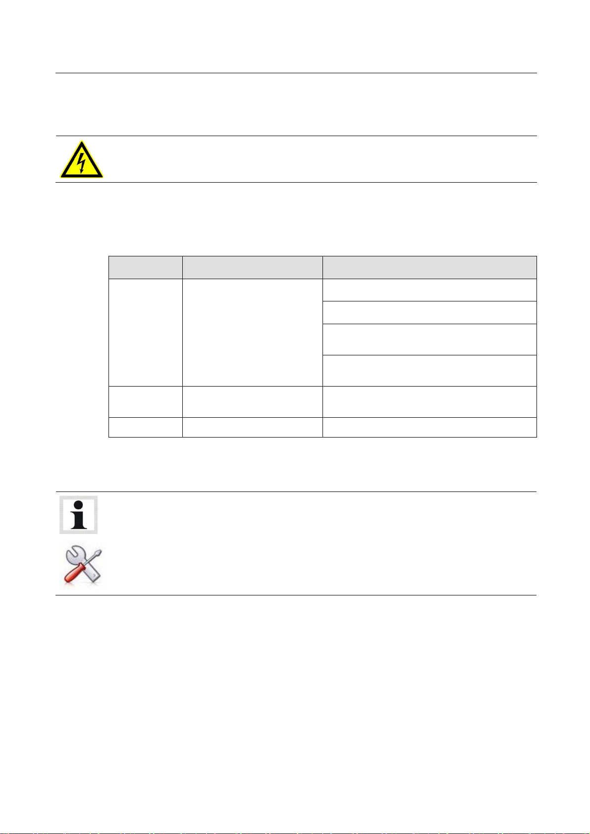
Important safety instructions. Failure to comply with instructions could result in personal injury or
property damage.
3
Important information.
Pos: 9 /Technische Dokumentation/Alle Geräte/01/ Überschriften/ Überschriften 1.1/ B/Überschrift 1.1: Bestimmungsgemäßer Gebr auch @ 6\mod_1176734022 203_75.docx @ 88746 @ 2 @ 1
1.3 Intended Use
Pos: 10 /Technische Dokumentation/Hebetechnik/00 HB Z Alle/01/Inhalte/Inha lt: Bestimmungsge mäßer Gebrauch HBZ @ 18\mod_1258 013896259_75.doc x @ 521484 @ @ 1
This lift shall be used exclusively for the safe lifting of motor vehicles. Observe the rated load
capacity.
The lift shall not be modified without the express written consent of the manufacturer. In case
Pos: 11 /Technische Dokumentation/Alle Geräte/01/ Überschriften/Ü berschriften 1.1/ S/Überschrift 1.1: Sicherheitsvorschri ften für die Inbetri ebnahme @ 6\mod_117448226915 6_75.docx @ 76838 @ 2 @ 1
1.4 Safety Instructions for Commissioning
Pos: 12 /Technische Dokumentation/Papierkorb/ Hebetechnik/Inhal t: Sicherheitsvorsc hriften für die I nbetriebnahme HBZ (2013-06-24 13: 12:08) @ 6\mod_117741 4876562_75.docx @ 90054 @ @ 1
of non-compliance the declaration of conformity becomes void.
The lift shall be installed and commissioned by authorized service personnel only.
The control desk shall not be installed in the danger zone of the lift.
The standard lift version shall not be installed and commissioned in hazardous locations,
Pos: 13 /-----Format-----/MANUELLER UMBRUCH Seitenumbruch @ 0\mod_1134403577687_0.docx @ 1277 @ @ 1
outdoors or in moist rooms (e.g. car wash).
BA082701-en
Page 4

4
Pos: 14 /Technische Dokumentation/Alle Geräte/01/ Überschriften/Ü berschriften 1.1/ S/Überschrift 1.1: Sicherheitsvorschri ften für den Betrieb @ 6\ mod_1174482268953_75. docx @ 76826 @ 2 @ 1
1.5 Safety Instructions for Operation
Pos: 15 /Technische Dokumentation/Papierkorb/ Hebetechnik/Inhal t: Sicherheitsvorsc hriften für den Betri eb (2011-03-01 09:04:20) @ 6\mod_1180597046593_ 75.docx @ 94462 @ @ 1
Read the detailed operating manual.
Lift operation by trained personnel over 18 years only.
Drive on the lift only when it is in bottom position.
Ensure an unobstructed movement of lift and vehicle.
After raising the vehicle briefly, stop and check the lift supports for secure contact.
Make sure the vehicle doors are closed during raising and lowering cycles.
Closely watch lift and vehicle during raising and lowering cycles.
Do not allow anyone to stay in lift area during raising and lowering cycles.
Do not allow anyone to climb up the lift or the raised vehicle.
Comply with the applicable accident prevention regulations.
Do not exceed the rated load capacity as indicated on the lift nameplate.
Only use the vehicle manufacturer's recommended lift points.
Do not use the lift for transporting persons.
After positioning the vehicle on the lift secure it against roll-off.
Keep lift and vehicle free of tools and parts.
Keep the lift and lift area clean.
The main switch serves as emergency switch. In case of emergency turn it to position "0".
Protect all parts of the electrical equipment from humidity.
Protect the lift against unauthorized usage by padlocking the main switch.
Pos: 16 /Technische Dokumentation/Alle Geräte/01/ Überschriften/Ü berschriften 1.1/ S/Überschrift 1.1: Sicherheitsvorschri ften für Servicear beiten @ 6\mod_117448227064 0_75.docx @ 76850 @ 2 @ 1
Use caution with operating vehicle engines. Danger of poisoning!
1.6 Safety Instructions for Servicing
Pos: 17 /Technische Dokumentation/Papierkorb/ Hebetechnik/Inhal t: Sicherheitsvorsc hriften für Servic earbeiten HBZ (2011-03-01 0 9:53:00) @ 7\mod_11961768 12580_75.docx @ 133711 @ @ 1
Service work may be done by authorized service technicians only.
Turn off and padlock the main switch before doing any repair, maintenance or setup work.
Work on pulse generators or proximity switches may be done by authorized service
technicians only.
Work on the electrical equipment may be done by service technicians or certified electricians
only.
Ensure that ecologically harmful substances are disposed of only in accordance with the
appropriate regulations.
Do not use high pressure or steam jet cleaners. Do not use caustic cleaning agents.
The lift's safety devices must be set by authorized service technicians.
Pos: 18 /-----Format-----/MANUELLER UMBRUCH Seitenumbruch @ 0\mod_1134403577687_0.docx @ 1277 @ @ 1
Do not replace or override the safety devices.
BA082701-en
Page 5

Pos: 19 /Technische Dokumentation/Alle Geräte/01/ Überschriften/Ü berschriften 1/T/ Überschrift 1: Technisc he Daten @ 6\mod_117448247 3078_75.docx @ 76986 @ 1 @ 1
2 Specifications
Pos: 20 /Technische Dokumentation/Hebetechnik/08 Sc heren-Hebebühnen/2701 MPL 3.5/ BA/Inhalt: 0827 Technische D aten (Bild) @ 12\mod_1232 981279958_0.docx @ 323241 @ @ 1
5
G
N
Pos: 21 /Technische Dokumentation/Hebetechnik/08 Sc heren-Hebebühnen/2701 MPL 3.5/ BA/Inhalt: 0827 Technische D aten (Tabelle) @ 15\mod _1244190423627_75.doc x @ 386396 @ @ 1
G Master side N Slave side
Load capacity 3500 kg
Lifting height H 450 mm
Width of support plate B 683 mm
Overall length Lmin...Lmax 1500…2008 mm
Pos: 22 /-----Format-----/MANUELLER UMBRUCH Seitenumbruch @ 0\mod_1134403577687_0.docx @ 1277 @ @ 1
MPL 3.5
BA082701-en
Page 6

6
Pos: 23 /Technische Dokumentation/Alle Geräte/01/ Überschriften/Ü berschriften 1/B/ Überschrift 1: Bedienung @ 6\ mod_1174482271218 _75.docx @ 76877 @ 1 @ 1
3 Operation
Pos: 24 /Technische Dokumentation/Hebetechnik/00 HB Z Alle/01/Inhalte/W arnung!/Inhalt: W arnung - Sicherheitshin weise für die Bedienung @ 6\mod_11 80600779281_75.doc x @ 94475 @ @ 1
Lift operation by trained personnel over 18 years only.
Do not exceed the rated load capacity as indicated on the lift nameplate.
Do not allow anyone to stay in lift area during raising and lowering cycles.
Closely watch lift and vehicle during raising and lowering cycles.
Make sure the vehicle doors are closed during raising and lowering cycles.
The lift area which cannot be seen by the operator during raising and lowering cycles must
be observed by a second person.
After raising the vehicle briefly, stop and check the lift supports for secure contact with the
vehicle.
Do not allow anyone to climb up the lift or the raised vehicle.
Pos: 25 /Technische Dokumentation/Alle Geräte/01/ Überschriften/Ü berschriften 1.1/ V/Überschrift 1.1: Verhalten im Störfall @ 6\mod_1 178097008375_75.doc x @ 90829 @ 2 @ 1
3.1 What to Do in the Event of Defects or Malfunctions
Pos: 26 /Technische Dokumentation/Hebetechnik/00 HB Z Alle/01/Inhalte/W arnung!/Inhalt: W arnung - Verhalten im Störfal l @ 6\mod_1178097081984_75. docx @ 90843 @ @ 1
In case of defects or malfunctions such as uncontrolled lift movement or deformation of the
superstructure, support or lower the lift immediately.
Turn off the main switch and secure it against unauthorized usage. Contact service.
Pos: 27 /Technische Dokumentation/Alle Geräte/01/ Überschriften/Ü berschriften 1.1/ H/Überschrift 1.1: Hauptschalter @ 6\mod_11775 92858312_75.doc x @ 90635 @ 2 @ 1
3.2 Main Switch
Pos: 28 /Technische Dokumentation/Hebetechnik/00 HB Z Alle/01/Inhalte/Inha lt: Hauptschalter mit NOT-AUS-Funktion HBZ (201 1-01-24 14:07:56) @ 6\mod_1180959351171_75. docx @ 95046 @ @ 1
The main switch is used as emergency switch. In case of emergency turn it to position 0.
Main switch in position 0: Power supply is interrupted
Main switch in position 1: Lift is ready for operation
Pos: 29 /-----Format-----/MANUELLER UMBRUCH Seitenumbruch @ 0\mod_1134403577687_0.docx @ 1277 @ @ 1
BA082701-en
Page 7

Pos: 30 /Technische Dokumentation/Alle Geräte/01/ Überschriften/Ü berschriften 1.1/ Versioniert/Übersc hrift 1.1: Bedi enelemente1 @ 6\mod_11806083 33156_75.docx @ 94515 @ 2 @ 1
3.3 Controls
Pos: 31 /Technische Dokumentation/Hebetechnik/08 Sc heren-Hebebühnen/2701 MPL 3.5/ BA/Inhalt: 0827 Bedienele mente (Bild) @ 14\mod_1240490 485134_0.docx @ 366990 @ @ 1
7
F G HE
Pos: 32 /Technische Dokumentation/Hebetechnik/08 Sc heren-Hebebühnen/2701 MPL 3.5/ BA/Inhalt: 0827 Bedienele mente (Text) @ 12\mod_1232 970579535_75.doc x @ 322847 @ @ 1
Control desk Remote control
A Main switch E Emergency Off Key
B Double button RAISE / LOWER F Button RAISE
C Indicator lamp "Remote control active" G Button LOWER
D Indicator lamp "10 t axle load, traversable" H Selector switch Control desk/Remote control
Pos: 33 /Technische Dokumentation/Hebetechnik/08 Sc heren-Hebebühnen/2701 MPL 3.5/ BA/Inhalt: 0827 Info - Bedi enelemente @ 12\mod_123304 4237646_75.docx @ 323328 @ @ 1
When the remote control is enabled ( indicator lamp C lighting up), double button B is
disabled.
Main switch and emergency stop button are permanently enabled.
Pos: 34 /-----Format-----/MANUELLER UMBRUCH Seitenumbruch @ 0\mod_1134403577687_0.docx @ 1277 @ @ 1
A B C D
BA082701-en
Page 8

8
Pos: 35 /Technische Dokumentation/Alle Geräte/01/ Überschriften/Ü berschriften 1.1/ H/Überschrift 1.1: Heben und Senken @ 6\mod_1178 521944593_75.docx @ 9123 7 @ 2 @ 1
3.4 Raising and Lowering
Pos: 36 /Technische Dokumentation/Hebetechnik/08 Sc heren-Hebebühnen/2701 MPL 3.5/ BA/Inhalt: 0827 Info - FZG symme trisch aufnehmen @ 16\mod_1 246368095891_75.d ocx @ 399570 @ @ 1
Make sure the vehicle is lifted symmetrically!
Pos: 37 /Technische Dokumentation/Hebetechnik/08 Sc heren-Hebebühnen/2701 MPL 3.5/ BA/Inhalt: 0827 Heben und Senke n @ 12\mod_1232971423414_7 5.docx @ 322870 @ @ 1
1 Turn the main switch to position 1.
Lift is ready for operation.
2 Choose the operating unit (control desk or remote control) using the selector switch. The
white indicator lamp lights up when the remote control is enabled.
3 Push and hold RAISE button until lift reaches desired height.
Lift stops once button is released or upper limit stop is reached.
4 Push and hold LOWER button until lift reaches desired height.
Lift stops once button is released or CE safety stop is reached.
Risk of injury!
Before lowering the lift to bottom position, verify that there are no persons or obstructions in the
danger area.
4 To lower the lift completely, release the LOWER button and press it again.
Lift motion to the lower limit stop is accompanied by an audible signal.
Once the support plates are in bottom position, the lift is traversable with an axle load of 10 t.
This status is confirmed by the green indicator lamp.
Pos: 38 /Technische Dokumentation/Alle Geräte/01/ Überschriften/Ü berschriften 1.1/ S/Überschrift 1.1: Sicherung gegen unbefugte Ben utzung @ 6\mod_11781135 26515_75.docx @ 90882 @ 2 @ 1
3.5 Protection against Unauthorized Usage
Pos: 39 /Technische Dokumentation/Hebetechnik/00 HB Z Alle/01/Inhalte/Inf o!/Inhalt: Info - Hauptschalter/Sic herung gegen unbefugte Benutzun g @ 8\mod_12033387827 58_75.docx @ 147325 @ @ 1
When in position 0, the main switch can be protected against tampering
by means of a padlock.
Pos: 40 /-----Format-----/MANUELLER UMBRUCH Seitenumbruch @ 0\mod_1134403577687_0.docx @ 1277 @ @ 1
BA082701-en
Page 9

Y
Y1.Y
Pos: 41 /Technische Dokumentation/Alle Geräte/01/ Überschriften/ Überschriften 1.1/ H/Überschrift 1. 1: Hydrauliksystem entlüf ten @ 6\mod_118053144404 6_75.docx @ 94390 @ 2 @ 1
3.6 Bleeding the Hydraulic System
Pos: 42 /Technische Dokumentation/Hebetechnik/00 HB Z Alle/01/Inhalte/Inf o!/Inhalt: Info - Entlüftung durch Servic e @ 14\mod_1239951513310_75. docx @ 361778 @ @ 1
Bleeding of hydraulic system is done by authorized service technicians.
9
Pos: 43 /Technische Dokumentation/Alle Geräte/01/ Überschriften/ Überschriften 1.1/ M/Überschrift 1. 1: Manuelles Absenken @ 6\mod_117 8113285703_75.doc x @ 90869 @ 2 @ 1
3.7 Manual Lowering
Pos: 44 /Technische Dokumentation/Hebetechnik/00 HB Z Alle/01/Inhalte/W arnung!/Inhalt: W arnung - Manuelles Absenken nur durch geschultes Perso nal @ 6\mod_11809622176 87_75.docx @ 95217 @ @ 1
Authorized personnel only! Do not restart the lift before the error has been remedied.
Pos: 45 /Technische Dokumentation/Hebetechnik/08 Sc heren-Hebebühnen/2701 MPL 3.5/ BA/Inhalt: 0827 Manuelles A bsenken (Bilder) @ 14\mod_1240491382058_0.doc x @ 367017 @ @ 1
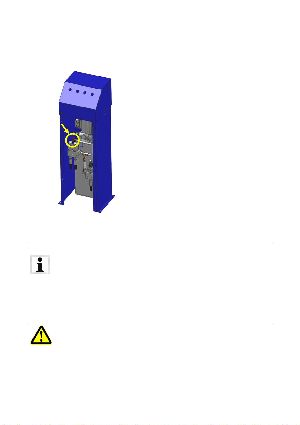
Pos: 46 /Technische Dokumentation/Hebetechnik/08 Sc heren-Hebebühnen/2701 MPL 3.5/ BA/Inhalt: 0827 Manuelles A bsenken (Text) @ 12\mod_123 2702342162_75.doc x @ 320960 @ @ 1
If the lift lowers although valves Y1 / Y1.1 are not being actuated, or if the support plates raise
and lower unevenly, open the knurled screw at valve Y2 immediately, shut down the lift and
contact the service department.
1 Remove the front cover of the control desk.
2 Close knurled screw at valve Y2 .
3 Press valves Y1 und Y1.1 simultaneously until the lift lowers.
4 While lowering, check that both support plates are at the same level.
5 As soon as the lift is in bottom position, release valves Y1 und Y1.1 and open the knurled
Pos: 47 /-----Format-----/MANUELLER UMBRUCH Seitenumbruch @ 0\mod_1134403577687_0.docx @ 1277 @ @ 1
screw at valve Y2.
1
BA082701-en
Page 10

10
Pos: 48 /Technische Dokumentation/Alle Geräte/01/ Überschriften/Ü berschriften 1.1/ Q/Überschrift 1.1: Quertraverse @ 17\mod_1251 387833213_75.doc x @ 431340 @ 2 @ 1
3.8 Transverse Beam
Pos: 49 /Technische Dokumentation/Hebetechnik/08 Sc heren-Hebebühnen/2701 MPL 3.5/ BA/Inhalt: 0827 Quertra verse, Option (Text) @ 17\ mod_1251384841108_75. docx @ 431284 @ @ 1
Intended Use
The transverse beam is optionally available. It is designed for lifting vehicles whose support
points are outside the support range of the lifting unit.
Scope of Delivery
Transverse beam (2 pcs.), aluminium, powder coated.
Accessories
Support blocks (required):
340 x 132 x 47 mm (VZ 975069) or 340 x 150 x 95 mm (VZ 970045)
Important Operating Instructions
Make sure the transverse beam (A) is positioned symmetrically on the surface of the wheel-
free jack (check using yellow marking!).
Position the support blocks (B) on the antiskid coating.
Note the colour marking:
Yellow (C) = This section must be positioned fully on the support plate of the lifting unit.
Black (D) = Antiskid coating. Engage the vehicle only in this section.
Red (E) = Do not engage the vehicle in this section.
Do not exceed rated distances and load capacity (see illustration).
Pos: 50 /Technische Dokumentation/Hebetechnik/08 Sc heren-Hebebühnen/2701 MPL 3.5/ BA/Inhalt: 0827 Quertra verse, Option (Bilder 1) @ 17\mod_1251704499368_ 0.docx @ 431773 @ @ 1
Pos: 51 /-----Format-----/MANUELLER UMBRUCH Seitenumbruch @ 0\mod_1134403577687_0.docx @ 1277 @ @ 1
A
= 875 mm
min
= 1100 mm
LW
max
F
= 750 kg • g
max
BA082701-en
Page 11

Pos: 52 /Technische Dokumentation/Hebetechnik/08 Sc heren-Hebebühnen/2701 MPL 3.5/ BA/Inhalt: 0827 Quertra verse, Option (Bilder 2) @ 17\mod_1251386631900_ 0.docx @ 431311 @ @ 1
11
B
A
D
Pos: 53 /-----Format-----/MANUELLER UMBRUCH Seitenumbruch @ 0\mod_1134403577687_0.docx @ 1277 @ @ 1
C
E
D
C
BA082701-en
Page 12
12
Pos: 54 /Technische Dokumentation/Papierkorb/ Überschriften/Über schrift 1: Instandha ltung @ 11\mod_1231318 736629_75.docx @ 28955 0 @ 1 @ 1
4 Maintenance
Pos: 55 /Technische Dokumentation/Alle Geräte/01/ Inhalte/War nung!/Inhalt: War nung - Hauptschalter aus bei Inst andhaltung @ 14\mod_124023 9070975_75.doc x @ 362949 @ @ 1
Danger! Electric shock hazard!
Before doing any maintenance work, turn off the main switch and protect it against tampering.
Pos: 56 /Technische Dokumentation/Alle Geräte/01/Überschriften/Überschriften 1.1/I/Überschrift 1.1: Instandhaltungsplan @ 11\mod_1231318919401_75.docx @ 289622 @ 2 @ 1
4.1 Maintenance Schedule
Pos: 57 /Technische Dokumentation/Hebetechnik/08 Sc heren-Hebebühnen/2701 MPL 3.5/ BA/Inhalt: 0827 Instandha ltungsplan @ 12\mod_1233057 563744_75.doc x @ 324058 @ 2 @ 1
Interval Maintenance items Procedure
3 months Hydraulic system
6 months Hydraulic fluid
12 months General inspection Check all components for damage.
Pos: 58 /Technische Dokumentation/Papierkorb/ Überschriften/Über schrift 1.1: Jähr liche Überprüfung @ 6\mod_11 74482245718_75.doc x @ 76817 @ 2 @ 1
Check fluid level, refill if necessary.
Check hydraulic system for tightness.
Check sealing cups for damage, replace if
necessary.
Check power unit for unusual noise during
operation, check fastening screws for tight fit.
Check fluid for soiling and aging, replace if
necessary.
4.2 Annual Inspection
Pos: 59 /Technische Dokumentation/Alle Geräte/01/ Inhalte/Info! /Inhalt: Info - Jährli che Überprüfung @ 14\mod_12420 51457491_75.doc x @ 373548 @ 2 @ 1
The maintenance interval prescribed by the manufacturer is 12 (twelve) months.
This maintenance interval refers to normal workshop usage. If the equipment is used more
frequently or under severe operating conditions (e.g. outdoors), the interval must be reduced
accordingly.
Maintenance work shall be done only by authorized and trained service technicians provided
by the manufacturer, licensed dealers or service partners.
In case of non-compliance the manufacturer's warranty becomes void.
Pos: 60 /Technische Dokumentation/Hebetechnik/00 HB Z Alle/01/Inhalte/Inf o!/Inhalt: Info - BGR 500 / BGG 945 Jährliche Überprüf ung @ 7\mod_1196177427630_75. docx @ 133733 @ @ 1
Pos: 61 /-----Format-----/MANUELLER UMBRUCH Seitenumbruch @ 0\mod_1134403577687_0.docx @ 1277 @ 2 @ 1
BA082701-en
Page 13
Pos: 62 /Technische Dokumentation/Alle Geräte/01/ Überschriften/Ü berschriften 1.1/ H/Überschrift 1.1: Hydrauliköl nachfüllen @ 6\ mod_1180614998015_75. docx @ 94590 @ 2 @ 1
4.3 Refilling with Hydraulic Fluid
Pos: 63 /Technische Dokumentation/Hebetechnik/08 Sc heren-Hebebühnen/2701 MPL 3.5/ BA/Inhalt: 0827 Hydraulik öl nachfüllen (Bild) @ 12\mod_1233052464874_ 0.docx @ 323614 @ @ 1
13
Pos: 64 /Technische Dokumentation/Hebetechnik/08 Sc heren-Hebebühnen/2701 MPL 3.5/ BA/Inhalt: 0827 Ölstand prüf en (Text) @ 12\mod_123297 6039115_75.docx @ 323186 @ @ 1
1 Check hydraulic fluid level every 3 months with a completely lowered lift.
Pos: 65 /Technische Dokumentation/Hebetechnik/00 HB Z Alle/01/Inhalte/Inf o!/Inhalt: Info - Tausch von Öl und Druckschläuche n @ 14\mod_1239952209207_ 75.docx @ 361832 @ 2 @ 1
2 Add missing fluid via the filler inlet. Make sure hydraulic fluid meets HLPD 32 specification.
Replace the hydraulic fluid periodically, depending on aging, soiling and water absorption.
When topping up, use fluid with the same specification only.
If the lift is operated permanently at an ambient temperature of < 15 °C, use hydraulic fluid
with a lower viscosity.
The pressure hoses should be replaced as required, but after six years at the latest.
Pos: 66 /Technische Dokumentation/Alle Geräte/01/ Überschriften/Ü berschriften 1.1/ R/Überschrift 1.1: Reinigung @ 6\mod_117861767 7265_75.docx @ 91586 @ 2 @ 1
4.4 Cleaning
Pos: 67 /Technische Dokumentation/Papierkorb/a lt/Inhalt: Reinigu ng HBZ @ 7\mod_1197289850229_ 75.docx @ 137426 @ @ 1
Pos: 68 /Technische Dokumentation/Alle Geräte/01/ Inhalte/War nung!/Inhalt: War nung - Beschädigungsgefahr/R einigung @ 14\mod_1239 952020489_75.doc x @ 361805 @ @ 1
Periodically wash off aggressive substances and treat the lift with oil or wax spray.
Risk of damage!
Do not use high pressure or steam jet cleaners. Do not use caustic cleaning agents.
Pos: 69 /-----Format-----/MANUELLER UMBRUCH Seitenumbruch @ 0\mod_1134403577687_0.docx @ 1277 @ 1 @ 1
BA082701-en
Page 14

14
Pos: 70 /Technische Dokumentation/Alle Geräte/01/ Überschriften/Über schriften 1/F/ Überschrift 1: Fehlerbeh ebung @ 6\mod_1177501739 937_75.docx @ 90397 @ 1 @ 1
5 Troubleshooting
Pos: 71 /Technische Dokumentation/Hebetechnik/08 Sc heren-Hebebühnen/2701 MPL 3.5/ BA/Inhalt: 0827 Fehlerbeheb ung @ 16\mod_1246357193762 _75.docx @ 399250 @ @ 1
Error Diagnosis Remedy
Main switch turned off. Turn on main switch.
Power failure. Check for cause of p. failure.
Lift does not run.
Lift does not raise.
Lift capacity insufficient.
Lift does not lower.
Support plates lower without
control button being pressed.
Power cord interrupted. Replace defective cord.
Fuses defective. Replace fuses.
Selector switch in wrong position.
Reverse motor rotation.
Turn switch to correct position.
Interchange two phases at
main switch.
Low fluid level. Top up fluid reservoir.
RAISE button defective.
Check button and line, replace
if necessary.
Pump intake filter dirty. Check and clean filter.
Valve Y2 disabled after manual
lowering.
Enable valve Y2 by opening
the knurled screw.
Pressure valves maladjusted.
Contact service.
Pump defective.
LOWER solenoid valve
defective.
Contact service.
LOWER button defective.
LOWER solenoid valve does
not close completely.
Leakage in at least two
hydraulic lines.
Contact service.
Check connections for tight fit
and hoses for damage,
replace if necessary.
Lift shows jerky movements. Air in hydraulic system. Contact service.
Support plates tilted – in
same direction.
Support plates tilted –
towards outside or inside.
Pos: 72 /-----Format-----/MANUELLER UMBRUCH Seitenumbruch @ 0\mod_1134403577687_0.docx @ 1277 @ 1 @ 1
BA082701-en
Vehicle lifted asymmetrically. Lift vehicle symmetrically.
Incorrect cylinder connection.
Contact service to have
cylinder connection corrected.
Page 15

Pos: 73 /Technische Dokumentation/Alle Geräte/01/ Überschriften/Über schriften 1/F/ Überschrift 1: Fir men-Information @ 7\mod_11873 38625828_75.doc x @ 104047 @ 1 @ 1
6 Company Information
Pos: 74 /Technische Dokumentation/Alle Geräte/01/ Inhalte/Inhalt: Fi rmen-Information MAHA (2013-05-24 11:04:40) @ 24\mod_1306832255635_75. docx @ 1015141 @ @ 1
© MAHA Maschinenbau Haldenwang GmbH & Co. KG
Legal notice based on ISO 16016:
The reproduction, distribution and utilization of this document as well as the communication of
its contents to others without explicit authorization is prohibited. Offenders will be held liable for
the payment of damages. All rights reserved in the event of the grant of a patent, utility model or
design.
The contents of this edition have been checked with great care. However, errors cannot be fully
excluded. Subject to technical change without notice.
Document
Document №: BA082701-en
Approval Date: 25.11.2009
Manufacturer
MAHA Maschinenbau Haldenwang GmbH & Co. KG
Hoyen 20
87490 Haldenwang
Germany
Phone: +49 (0) 8374 585 0
Fax: +49 (0) 8374 585 590
Fax Parts: +49 (0) 8374 585 565
Internet: http://www.maha.de
E-Mail: maha@maha.de
Hotline: +49 (0) 180 56242 60 for Brake Testers and Test Lanes
+49 (0) 180 56242 80 for Automotive Lifts
+49 (0) 180 56242 90 for Dynamometers and Emission Testers
15
Service
=== Ende der Liste für Textmarke Inhalt ===
AutomoTec GmbH
Maybachstraße 8
87437 Kempten
Germany
Phone: +49 (0) 180 56242 50
Fax: +49 (0) 180 56242 55
Internet: http://www.automo-tec.com
E-Mail: service@automo-tec.com
BA082701-en
 Loading...