

Page 1
Fehler! Verwenden Sie die Registerkarte 'Start', um Name dem Text zuzuweisen, der hier angezeigt werden soll.Fehler! Verwenden Sie
die Registerkarte 'Start', um Name dem Text zuzuweisen, der hier angezeigt werden soll.Fehler! Verwenden Sie die Registerkarte
'Start', um Name dem Text zuzuweisen, der hier angezeigt werden soll.
MLT 1000 MB
Headlight Tester
Original Operating Instructions
BA380801_001-en
Pos: 1 /Produktfamilien/Scheinwerfereinstellprüftechnik/MLT-SERIES/380801 MLT 1000/380801_001 MLT 1000 MB/BA/Inhalt: 3808_001 Titelb ild @ 55\mod_1552902148092_ 0.docx @ 3126311 @ @ 1
Pos: 2 /-----For mat-----/MANUELLER UMBRUCH Se itenumbruch @ 0\mod_1134403577687_0. docx @ 1277 @ @ 1
Page 2

2
Contents
1
Safety .................................................................................................................... 4
2
Description ............................................................................................................ 5
3
Operation ............................................................................................................. 11
4
Maintenance ........................................................................................................ 15
5
Disposal ............................................................................................................... 15
6
Inspection Equipment Monitoring .......................................................................... 16
Pos: 3 /-----Format-----/ Inhaltsverzeichnis - 3 Ebenen @ 5\mod_1168867441046_75.do cx @ 72920 @ @ 1
1.1 Introduction .............................................................................................................. 4
1.2 Intended Use ........................................................................................................... 4
1.3 Safety Instructions .................................................................................................... 4
2.1 Requirements for the Place of Installation ................................................................. 5
2.2 Specifications ........................................................................................................... 5
2.3 Equipment Overview ................................................................................................ 6
2.4 Projection Screen ..................................................................................................... 7
2.5 Setting Wheel ........................................................................................................... 8
2.6 Definition of Technical Terms .................................................................................... 9
2.6.1 Pitch Angle ............................................................................................................... 9
2.6.2 Low Beam ............................................................................................................... 9
2.6.3 High Beam ............................................................................................................. 10
3.1 Positioning the Vehicle ........................................................................................... 11
3.2 Using the Colour Filter ............................................................................................ 12
3.3 Setting the Headlights ............................................................................................ 13
3.4 Measuring the Luminous Intensity / Illuminance ...................................................... 14
3.4.1 Low Beam ............................................................................................................. 14
3.4.2 High Beam ............................................................................................................. 14
4.1 Installing the Cover Hood ....................................................................................... 15
4.2 Cleaning ................................................................................................................. 15
6.1 Vertical and Horizontal Alignment of Headlight Tester ............................................. 16
6.1.1 Vertical Alignment ................................................................................................... 17
6.1.2 Horizontal Alignment .............................................................................................. 18
6.2 Laser Calibration Set .............................................................................................. 19
6.3 Laser Positions ....................................................................................................... 19
6.4 Checking the Precision of the Laser Calibration Set ................................................ 20
6.5 Mechanical Inspection ............................................................................................ 21
6.6 Adjusting the Pointer Position ................................................................................. 22
6.6.1 Adjusting the Projection Area .................................................................................. 25
BA380801_001-en
Page 3

3
6.6.2 Calibration of the Luminous Intensity ...................................................................... 26
6.7 Inspection Certificates (Inspection Interval: Annually) ............................................... 27
Pos: 4 /-----For mat-----/MANUELLER UMBRUCH Se itenumbruch @ 0\mod_1134403577687_0. docx @ 1277 @ @ 1
BA380801_001-en
Page 4

4
1
Safety
1.1
Introduction
1.2
Intended Use
1.3
Safety Instructions
Pos: 5 /Produktfamilien/Alle Geräte/Überschriften/Überschriften 1/S/Überschrift 1: Sicherheit @ 6\mod_1174482399906_75.docx @ 76962 @ 1 @ 1
Pos: 6 /Produktfamilien/Alle Geräte/Überschriften/Überschriften 1.1/E/Überschrift 1.1: Einführung @ 6\mod_1174482219062_75.docx @ 76793 @ 2 @ 1
Pos: 7 /Produktfamilien/Alle Geräte/Inhalte/Sicherheit/Inhalt: Einführung Sicherheit_12pt @ 25\mod_1324455248318_75.docx @ 1138886 @ @ 1
Thoroughly read this manual before operating the equipment and comply with the
instructions. Always display the manual in a conspicuous location.
Personal injury and property damage incurred due to non-compliance with these
Pos: 8 /Produktfamilien/Alle Geräte/Überschriften/Überschriften 1.1/B/Überschrift 1.1: Bestimmungsgemäßer Gebrauch @ 6\mod_1176734022203_75.docx @ 88746 @ 2 @ 1
Pos: 9 /Produktfamilien/Scheinwerfereinstellprüftechnik/MLT-SERIES/380701 MLT 3000/BA/Inhalt: 3807 Bestimmungsgemäß er Gebrauch_12pt @ 26\mo d_1325493887453_75.d ocx @ 1142050 @ @ 1
safety instructions are not covered by the product liability regulations.
This device only serves to check and adjust the alignment of vehicle headlights.
This device cannot be modified without the express, written consent of the
Pos: 10 /Produktfamilien/Alle Geräte/Überschriften/Überschriften 1.1/S/Überschrift 1.1: Sicherheitsvorschriften @ 8\mod_1204545563175_75.docx @ 155576 @ 2 @ 1
manufacturer. Any infringement renders the conformity declaration invalid.
Pos: 11 /Produktfamilien/Scheinwerfereinstellprüftechnik/MLT-SERIES/380801 MLT 1000/380801_001 MLT 1000 MB/BA/Inhalt: 3808_001 Sicherheit svorschriften @ 44\mo d_1457449893272_75.d ocx @ 2417834 @ @ 1
• This device must only ever be operated within its performance limits.
• All service work must be performed by service technicians employed by the
manufacturer or by authorized service partners.
• Never expose the lens to direct sunlight. The bundling of light may cause fire
damage inside the housing.
Pos: 12 /-----Format-----/MANUELLER UMBRUCH Seitenumbruch @ 0\mod_113440357768 7_0.docx @ 1277 @ @ 1
• Only ever clean the lens with a soft cloth and a glass cleaning agent.
BA380801_001-en
Page 5

5
2
Description
2.1
Requirements for the Place of Installation
2.2
Specifications
Pos: 13 /Produktfamilien/Alle Geräte/Überschriften/Überschriften 1/B/Überschrift 1: Beschreibung @ 6\mod_1174482271453_75.docx @ 76889 @ 1 @ 1
Pos: 14 /Produktfamilien/Alle Geräte/Überschriften/Überschriften 1.1/A/Überschrift 1.1: Anforderungen an den Aufstellort @ 7\mod_1184077643671_75.docx @ 99737 @ 2 @ 1
Pos: 15 /Produktfamilien/Scheinwerfereinstellprüftechnik/MLT-SERIES/380701 MLT 3000/BA/Inhalt: 3807 Anforderungen an de n Aufstellort @ 54\mod_ 1536212493413_75.doc x @ 3086120 @ @ 1
Pos: 16 /Produktfamilien/Alle Geräte/Überschriften/Überschriften 1.1/T/Überschrift 1.1: Technische Daten @ 7\mod_1184075526343_75.docx @ 99711 @ 2 @ 1
Pos: 17 /Produktfamilien/Scheinwerfereinstellprüftechnik/MLT-SERIES/380801 MLT 1000/380801_001 MLT 1000 MB/BA/Inhalt: 3808_001 Tech nische Daten (Tabel le) @ 44\mod_1458298222484_75. docx @ 2421724 @ @ 1
Please observe your national guidelines and specifications.
Measuring range
below 0…600 mm / 10 m (0…6 %)
left 0…1000 mm / 10 m (0…10 %)
right 0…1000 mm / 10 m (0…10 %)
Height of luminous centre 240…2000 mm
Measuring distance 100…500 mm
Intensity
Luminous intensity 0…40 000 cd (Candela)
Illuminance 0…64 lx (Lux)
Operating range
Temperature +5…+40 °C
Relative humidity 20…80 %
Dimensions (W x H x D) 655 x 2240 x 720 mm
Weight 65 kg
Pos: 18 /-----Format-----/MANUELLER UMBRUCH Seitenumbruch @ 0\mod_11344035 77687_0.docx @ 1277 @ @ 1
BA380801_001-en
Page 6
6
2.3
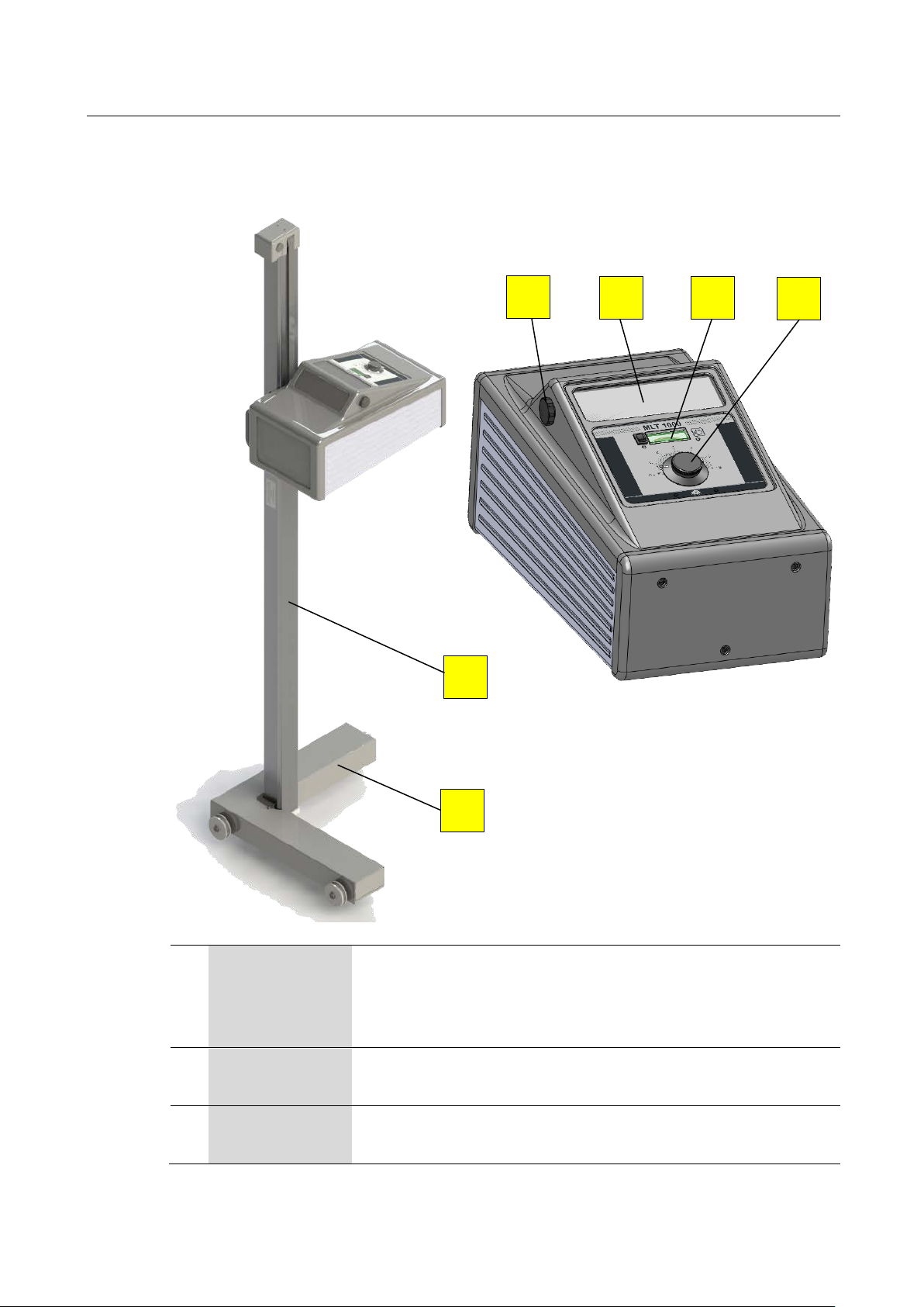
Equipment Overview
A
housing to the desired test height is located in the interior of
B
C
Pos: 19 /Produktfamilien/Alle Geräte/Überschriften/Überschriften 1.1/G/Überschrift 1.1: Geräteübersicht @ 7\mod_1184146948546_75.docx @ 99958 @ 2 @ 1
Pos: 20 /Produktfamilien/Scheinwerfereinstellprüftechnik/MLT-SERIES/380801 MLT 1000/380801_001 MLT 1000 MB/BA/Inhalt: 3808_001 Geräteübersic ht (Bild) @ 43\mod_1446725 097338_0.doc x @ 2332496 @ @ 1
A
C
D E
F
Pos: 21 /Produktfamilien/Scheinwerfereinstellprüftechnik/MLT-SERIES/380801 MLT 1000/380801_001 MLT 1000 MB/BA/Inhalt: 3808_001 Geräteübersic ht (Legende) @ 44\mod_145829 8297535_75.do cx @ 2421782 @ @ 1
Column The column envelopes a precision profile which carries the
Carriage The carriage can be moved on two rails perpendicular to
Knob for Folding Mirror
BA380801_001-en
B
slide rails. The counterweight which can be used to set the
the column (automatic locking).
the vehicle’s approach direction.
The projection screen in the housing can be observed in
the folding mirror.
Page 7

7
D
E
F
2.4
Projection Screen
A
B1
B2
C
D
Pos: 22 /Produktfamilien/Alle Geräte/Überschriften/Überschriften 1.1/P/Überschrift 1.1: Projektionsbildschirm @ 39\mod_1411987885858_75.docx @ 2107734 @ 2 @ 1
Pos: 23 /Produktfamilien/Scheinwerfereinstellprüftechnik/MLT-SERIES/380801 MLT 1000/BA/Inhalt: 3808 Projektionsbildschi rm (Text) @ 39\mod_14119879 55761_75.docx @ 2107780 @ @ 1
The projection screen is based on the test condition that the distance between
headlight and test surface is 10 m.
Use the folding mirror or the viewing window to observe the projection screen in
the housing on which the headlight beam is reproduced.
Pos: 24 /Produktfamilien/Scheinwerfereinstellprüftechnik/MLT-SERIES/380801 MLT 1000/BA/Inhalt: 3808 Projektionsbildschi rm (Bild) @ 39\mod_14119889 81796_0.docx @ 2107966 @ @ 1
The image on the projection screen is displayed 20 times smaller than the original.
Viewing Window
Light Measurement Unit
The projection screen in the housing can be viewed
through the viewing window.
The luminous intensity or illuminance of the headlights can
be checked using the light measurement unit.
When performing a light measurement, the colour filter
must be removed.
Setting Dial Use the setting dial to move the projection screen up and
down in the housing to achieve the desired inclination value.
Pos: 25 /Produktfamilien/Scheinwerfereinstellprüftechnik/MLT-SERIES/380801 MLT 1000/BA/Inhalt: 3808 Projektionsbil dschirm (Legende) @ 39\ mod_1411989256151_75. docx @ 2108392 @ @ 1
Dividing line = Reference axis for light-dark border of low beam
Tolerance mark (left) for inflection point of asymmetrical European low
beams
Tolerance mark (right) for inflection point of asymmetrical European low
beams
Central mark = Elementary point for setting the high beams
The outlined corners indicate the size of the test surface which is binding
based on the directives for vehicle headlight settings (e.g. in Germany).
Pos: 26 /-----Format-----/MANUELLER UMBRUCH Seitenumbruch @ 0\mod_11344035 77687_0.docx @ 1277 @ @ 1
BA380801_001-en
Page 8

8
2.5
Setting Wheel
Pos: 27 /Produktfamilien/Alle Geräte/Überschriften/Überschriften 1.1/E/Überschrift 1.1: Einstellrad @ 39\mod_1411989830719_75.docx @ 2108438 @ 2 @ 1
Pos: 28 /Produktfamilien/Scheinwerfereinstellprüftechnik/MLT-SERIES/380801 MLT 1000/BA/Inhalt: 3808 Einstellrad (Text) @ 39\mod_1411989 869640_75.docx @ 2108624 @ @ 1
Use the setting wheel to move the projection screen up or down in the housing.
As the inclination of the headlight hot spot in relation to the driving surface is
usually expressed in percentage, the setting wheel has a percentage (%) dial.
The inclination values (light-dark border of the vehicle headlights) can be set from
Pos: 29 /-----Format-----/MANUELLER UMBRUCH Zeilenschaltung @ 7\mod_ 1195138965731_0.do cx @ 132177 @ @ 1
Pos: 30 /Produktfamilien/Scheinwerfereinstellprüftechnik/MLT-SERIES/380801 MLT 1000/BA/Inhalt: 3808 Einstellrad (Bild) @ 39\mod_ 1411731880596_0.d ocx @ 2105262 @ @ 1
0 to -6 % using the dial.
Pos: 31 /-----Format-----/MANUELLER UMBRUCH Seitenumbruch @ 0\mod_11344035 77687_0.doc x @ 1277 @ @ 1
BA380801_001-en
Page 9
9
2.6
Definition of Technical Terms
2.6.1
Pitch Angle
2.6.2
Low Beam
Pos: 32 /Produktfamilien/Alle Geräte/Überschriften/Überschriften 1.1/B/Überschrift 1.1: Begriffsbestimmung @ 21\mod_1283338711724_75.docx @ 884333 @ 2 @ 1
Pos: 33 /Produktfamilien/Alle Geräte/Überschriften/Überschriften 1.1.1/N/Überschrift 1.1.1: Nickwinkel @ 25\mod_1319632959141_75.docx @ 1067583 @ 3 @ 1
Pos: 34 /Produktfamilien/Scheinwerfereinstellprüftechnik/- Archiv -/38 Scheinwerfer-Einstell-Prüfgeräte/0501 LITE 3/BA/Inhalt: 3805 Begriffsbestimmung (Bilder 1) @ 21\mod_1283343123850_0.docx @ 884364 @ @ 1
Pos: 35 /Produktfamilien/Scheinwerfereinstellprüftechnik/- Archiv -/38 Scheinwerfer-Einstell-Prüfgeräte/0501 LITE 3/BA/Inhalt: 3805 Begriffsbestimmung Nickwinkel @ 26\mod_1325495352529_75.doc x @ 1142312 @ @ 1
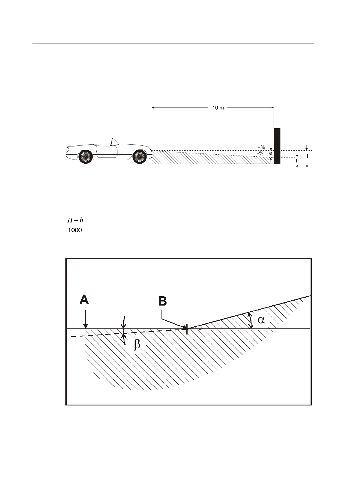
Angle of inclination of light-dark limit against the test surface.
The inclination of headlight lighting bundle against the test surface is expressed as
a percentage, using 10 m as a reference parameter:
X 100
Pos: 36 /Produktfamilien/Alle Geräte/Überschriften/Überschriften 1.1.1/A/Überschrift 1.1.1: Abblendlicht @ 25\mod_1319633029481_75.docx @ 1067613 @ 3 @ 1
Pos: 37 /Produktfamilien/Scheinwerfereinstellprüftechnik/- Archiv -/38 Scheinwerfer-Einstell-Prüfgeräte/0501 LITE 3/BA/Inhalt: 3805 Begriffsbestimmung (Bilder 2) @ 25\mod_1319631975821_0. docx @ 1067463 @ @ 1
Pos: 38 /-----Format-----/MANUELLER UMBRUCH Seitenumbruch @ 0\mod_11344035 77687_0.doc x @ 1277 @ @ 1
BA380801_001-en
Page 10
10
A
Light-dark limit
B
Inflection point
α
Yaw angle
α
Rolling angle
2.6.3
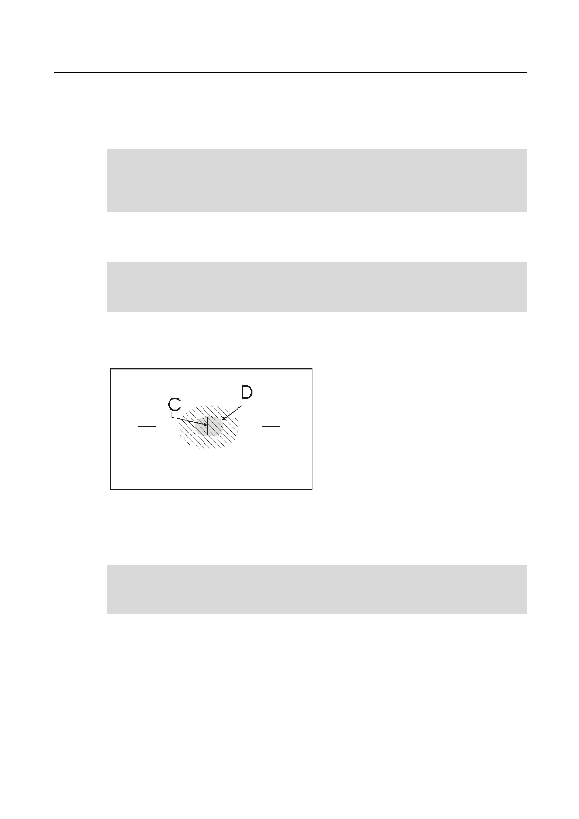
High Beam
C
Central mark
D
Hot spot
Pos: 39 /Produktfamilien/Scheinwerfereinstellprüftechnik/- Archiv -/38 Scheinwerfer-Einstell-Prüfgeräte/0501 LITE 3/BA/Inhalt: 3805 Begriffsbestimmung Abblendlicht @ 26\mod_1325495443262_75.docx @ 1142344 @ @ 1
Boundary for light distribution between ‘top dark’ and ‘bottom light’ for lowbeam lights.
Synonymous with the light-dark limit for asymmetric low-beam lighting. The
deviation of the inflection point is expressed in %. 10 meters is used as the
reference dimension.
Angle between the inflection point on the rising component of the light-dark
limit and the horizontal line for asymmetric low-beam light.
Angle between the left component of the light-dark limit and the horizontal,
usually 0°.
From the central mark, the deviation of hot-spot is specified in X and Y di-
Pos: 40 /Produktfamilien/Alle Geräte/Überschriften/Überschriften 1.1.1/F/Überschrift 1.1.1: Fernlicht @ 25\mod_1319633186648_75.docx @ 1067673 @ 3 @ 1
Pos: 41 /Produktfamilien/Scheinwerfereinstellprüftechnik/- Archiv -/38 Scheinwerfer-Einstell-Prüfgeräte/0501 LITE 3/BA/Inhalt: 3805 Begriffsbestimmung (Bilder 3) @ 25\mod_1319632161039_ 0.docx @ 1067493 @ @ 1
Pos: 42 /Produktfamilien/Scheinwerfereinstellprüftechnik/- Archiv -/38 Scheinwerfer-Einstell-Prüfgeräte/0501 LITE 3/BA/Inhalt: 3805 Begriffsbestimmung Fernlicht @ 26\mod_1325495528426_75.docx @ 1142376 @ @ 1
rections.
Center of light beam for high-beam. The deviation of hot spot from central
mark is expressed in %.10 meters is used as the reference dimension.
Pos: 43 /-----Format-----/MANUELLER UMBRUCH Seitenumbruch @ 0\mod_1134403577687_0.d ocx @ 1277 @ @ 1
BA380801_001-en
Page 11

11
3
Operation
3.1
Positioning the Vehicle
NOTE:
NOTE:
A
B
C
7 m (+2 m; -0,3 m)
Pos: 44 /Produktfamilien/Alle Geräte/Überschriften/Überschriften 1/B/Überschrift 1: Bedienung @ 6\mod_1174482271218_75.docx @ 76877 @ 1 @ 1
Pos: 45 /Produktfamilien/Alle Geräte/Überschriften/Überschriften 1.1/F/Überschrift 1.1: Fahrzeug positionieren @ 43\mod_1448264770844_75.docx @ 2345640 @ 2 @ 1
Pos: 46 /Produktfamilien/Scheinwerfereinstellprüftechnik/MLT-SERIES/380801 MLT 1000/380801_001 MLT 1000 MB/BA/Inhalt: 3808_001 Fahrzeug po sitionieren (Text) @ 46\ mod_1478767340257_75.d ocx @ 2775905 @ @ 1
• An adhesive film is stuck to the floor at a right angle to the guide rails as an
approach marking (see fig.). Length: 7 m (+2 m, -0.3 m), recommended length
for testing transporters and commercial vehicles: 9 m.
It is advisable to apply the approach marking with paint on floors with a nonslip coating.
• Position the vehicle’s left front wheel at the start of the approach marking.
Drive along the approach marking and precisely maintain the distance from
the left front wheel while doing so. Park the vehicle once the measuring distance (100 to 500 mm) has been reached.
The position of the left rear wheel does not have to be taken into
consideration. It varies due to differences in track width, mixed tyres, the rear
axle angle, etc.
In the case of right-hand drive vehicles, carry out the procedure for the right
front wheel with the approach marking back-to-front.
• A mirror (not included in the scope of delivery) can be used to help with posi-
tioning.
• Slide the headlight tester in front of the headlight to be adjusted.
Headlight tester
Pos: 47 /Produktfamilien/Scheinwerfereinstellprüftechnik/MLT-SERIES/380801 MLT 1000/380801_001 MLT 1000 MB/BA/Inhalt: 3808_001 Fahrzeug po sitionieren (Bild) @ 43\ mod_1448019010426_0.d ocx @ 2345339 @ @ 1
B
A
C
Guide rails
Approach marking
Pos: 48 /-----Format-----/MANUELLER U MBRUCH Seitenumbruch @ 0\mod_1134403577687_ 0.docx @ 1277 @ @ 1
BA380801_001-en
Page 12
12
3.2
Using the Colour Filter
LED1
Pos: 49 /Produktfamilien/Alle Geräte/Überschriften/Überschriften 1.1/F/Überschrift 1.1: Farbfilter verwenden @ 43\mod_1446730465505_75.docx @ 2332926 @ 2 @ 1
Pos: 50 /Produktfamilien/Scheinwerfereinstellprüftechnik/MLT-SERIES/380801 MLT 1000/380801_001 MLT 1000 MB/BA/Inhalt: 3808_001 Farb filter verwenden (Text ) @ 43\mod_1448019592049 _75.docx @ 2345435 @ @ 1
The “Orange” colour filter (Lee 105) has the
The colour filter must be removed when measuring the intensity (luminous intensity
Pos: 51 /Produktfamilien/Scheinwerfereinstellprüftechnik/MLT-SERIES/380801 MLT 1000/380801_001 MLT 1000 MB/BA/Inhalt: 3808_001 Farbfilter verwenden (Bild) @ 44\mod_1463737982530_0.do cx @ 2493441 @ @ 1
/ illuminance).
marking.
Pos: 52 /-----Format-----/MANUELLER UMBRUCH Seitenumbruch @ 0\mod_11344035 77687_0.docx @ 1277 @ @ 1
BA380801_001-en
Page 13

13
3.3
Setting the Headlights
Pos: 53 /Produktfamilien/Alle Geräte/Überschriften/Überschriften 1.1/SCH/Überschrift 1.1: Scheinwerfer einstellen @ 39\mod_1411990112061_75.docx @ 2108670 @ 2 @ 1
Pos: 54 /Produktfamilien/Scheinwerfereinstellprüftechnik/MLT-SERIES/380801 MLT 1000/BA/Inhalt: 3808 Scheinwerfer einstell en @ 39\mod_1412063328775_75. docx @ 2110194 @ @ 1
1 Switch on the headlights.
2 Set the projection screen to the required inclination value using the setting
3 The headlights should be tested individually, the other(s) should be turned off
4 Observe the projection screen. If the headlight setting is checked through the
5 Adjust the headlights until they match the applicable statutory directives.
Example: When setting the low beam, the dividing line is the reference line for the
inclination point of the light-dark border.
dial.
or covered if necessary.
folding mirror, note that all screen markings are displayed mirror-inverted.
Pos: 55 /-----Format-----/MANUELLER UMBRUCH Zeilenschaltung @ 7\mod_ 1195138965731_0.do cx @ 132177 @ @ 1
Pos: 56 /Produktfamilien/Scheinwerfereinstellprüftechnik/MLT-SERIES/380801 MLT 1000/BA/Inhalt: 3808 Hell-Dunke l-Grenze @ 39\mod_1412164287384_0.doc x @ 2110706 @ @ 1
Pos: 57 /-----Format-----/MANUELLER UMBRUCH Seitenumbruch @ 0\mod_11344035 77687_0.docx @ 1277 @ @ 1
BA380801_001-en
Page 14

14
3.4
Measuring the Luminous Intensity / Illuminance
Observe the following to maintain correct values:
3.4.1
Low Beam
3.4.2
High Beam
Pos: 58 /Produktfamilien/Alle Geräte/Überschriften/Überschriften 1.1/L/Überschrift 1.1: Lichtstärke / Beleuchtungsstärke messen @ 39\mod_1412072502243_75.docx @ 2110240 @ 2 @ 1
Pos: 59 /Produktfamilien/Scheinwerfereinstellprüftechnik/MLT-SERIES/380801 MLT 1000/380801_001 MLT 1000 MB/BA/Inhalt: 3808_001 Luxmeter (Text ) @ 44\mod_1454321015652_ 75.docx @ 2389162 @ @ 1
The luminous intensity or illuminance of the dipped beam and full beam are
displayed in lux (lx) and kilocandelas (kCd) with the light measuring equipment.
• The colour filter must be removed for the light measurement
• The headlight tester must be aligned to the headlight
• The headlights must be adjusted correctly
• The vehicle battery must be fully charged
Pos: 60 /Produktfamilien/Alle Geräte/Überschriften/Überschriften 1.1.1/A/Überschrift 1.1.1: Abblendlicht @ 25\mod_1319633029481_75.docx @ 1067613 @ 3 @ 1
Pos: 61 /Produktfamilien/Scheinwerfereinstellprüftechnik/MLT-SERIES/380801 MLT 1000/BA/Inhalt: 3808 Luxmeter Abblendlicht ( Bild) @ 39\mod_1412148572855_0. docx @ 2110522 @ @ 1
Pos: 62 /Produktfamilien/Scheinwerfereinstellprüftechnik/MLT-SERIES/380801 MLT 1000/BA/Inhalt: 3808 Luxmeter Abblendlicht ( Text) @ 39\mod_1412150554675_ 75.docx @ 2110614 @ @ 1
• Leave the vehicle engine running at a medium rotational speed
1 Switch on the low beams.
2 Position the toggle switch to low beam position (upwards).
3 Set the projection screen using the dial so that the dividing line lies on the
4 Read the value: The incoming light is extrapolated to 25 m and can be read
Pos: 63 /Produktfamilien/Alle Geräte/Überschriften/Überschriften 1.1.1/F/Überschrift 1.1.1: Fernlicht @ 25\mod_1319633186648_75.docx @ 1067673 @ 3 @ 1
Pos: 64 /Produktfamilien/Scheinwerfereinstellprüftechnik/MLT-SERIES/380801 MLT 1000/BA/Inhalt: 3808 Luxmeter Fernlicht (Bild) @ 39\mod_1412150238663_0.docx @ 2110568 @ @ 1
light-dark border.
off the upper scale.
Pos: 65 /Produktfamilien/Scheinwerfereinstellprüftechnik/MLT-SERIES/380801 MLT 1000/BA/Inhalt: 3808 Luxmeter Fernlicht (Te xt) @ 39\mod_1412151003238_75.do cx @ 2110660 @ @ 1
1 Switch on the low beams.
2 Set the projection screen using the dial so that the dividing line lies on the
light-dark border of the low beams.
3 Switch on the high beams.
4 Position the toggle switch to high beam position (downwards).
5 Read the value: The incoming light is extrapolated to 25 m and can be read
Pos: 66 /-----Format-----/MANUELLER UMBRUCH Seitenumbruch @ 0\mod_11344035 77687_0.docx @ 1277 @ @ 1
BA380801_001-en
off the lower scale.
Page 15

15
4
Maintenance
4.1
Installing the Cover Hood
4.2
Cleaning
5
Disposal
Pos: 67 /Produktfamilien/Alle Geräte/Überschriften/Überschriften 1/I/Überschrift 1: Instandhaltung @ 28\mod_1332159812536_75.docx @ 1565908 @ 1 @ 1
Pos: 68 /Produktfamilien/Alle Geräte/Überschriften/Überschriften 1.1/A/Überschrift 1.1: Abdeckhaube anbringen @ 43\mod_1446736689656_75.docx @ 2333255 @ 2 @ 1
Pos: 69 /Produktfamilien/Scheinwerfereinstellprüftechnik/MLT-SERIES/380701 MLT 3000/BA/Inhalt: 3807 Abdeckhaube anbringen @ 43\mod_ 1448008903745_75.doc x @ 2345007 @ @ 1
Attach the supplied cover hood when the tester is not being used. The hood is
Pos: 70 /Produktfamilien/Scheinwerfereinstellprüftechnik/MLT-SERIES/380801 MLT 1000/380801_001 MLT 1000 MB/BA/Inhalt: 3808_001 Abdeckha ube (Bild) @ 44\mod_1454319756780_ 0.docx @ 2389106 @ @ 1
used to protect against sunlight and other environmental influences.
Pos: 71 /Produktfamilien/Alle Geräte/Überschriften/Überschriften 1.1/R/Überschrift 1.1: Reinigung @ 6\mod_1178617677265_75.docx @ 91586 @ 2 @ 1
Pos: 72 /Produktfamilien/Scheinwerfereinstellprüftechnik/MLT-SERIES/380801 MLT 1000/BA/Inhalt: 3808 Instandhaltung @ 39\mod_1412088260570_75.d ocx @ 2110186 @ @ 1
This headlight tester is an optical measuring device and must therefore be handled
accordingly (i.e. with care).
The lens needs to be wiped regularly with a clean cloth and commercial glass
Pos: 73 /Produktfamilien/Alle Geräte/Überschriften/Überschriften 1/G/Überschrift 1: Geräteentsorgung @ 6\mod_1174482271625_75.docx @ 76901 @ 1 @ 1
Pos: 74 /Produktfamilien/Alle Geräte/Inhalte/Inhalt: Geräteentsorgung (ohne RiLi)_12pt @ 26\mod_1324467454724_75.docx @ 1140930 @ @ 1
cleaner. In all other respects, this is a zero-maintenance device.
If you want to dispose of the equipment, please contact your MAHA dealer or the
following address, indicating equipment type, date of purchase and serial number:
MAHA Maschinenbau Haldenwang GmbH & Co. KG
Hoyen 20
87490 Haldenwang
Germany
Phone: +49 (0) 8374 585 0
Fax: +49 (0) 8374 585 500
Pos: 75 /Produktfamilien/Alle Geräte/Inhalte/Inhalt: Geräteentsorgung über Fachbetrieb (alternativ)_12pt @ 26\mod_1324468120852_75.docx @ 1141022 @ @ 1
Email: altgeraete@maha.de
Alternatively, you may take the equipment to a specialised waste management
plant to ensure that all components and operating liquids are properly disposed
Pos: 76 /-----Format-----/MANUELLER UMBRUCH Seitenumbruch @ 0\mod_11344035 77687_0.docx @ 1277 @ @ 1
of.
BA380801_001-en
Page 16

16
6
Inspection Equipment Monitoring
6.1
Vertical and Horizontal Alignment of Headlight Tester
A
C
E
B
D
F
Pos: 77 /Produktfamilien/Alle Geräte/Überschriften/Überschriften 1/P/Überschrift 1: Prüfmittelüberwachung @ 44\mod_1454317304431_75.docx @ 2389014 @ 1 @ 1
Pos: 78 /Produktfamilien/Alle Geräte/Überschriften/Überschriften 1.1/V/Überschrift 1.1: Vertikale und horizontale Ausrichtung des SEP @ 44\mod_1457358616470_75.docx @ 2417510 @ 2 @ 1
Pos: 79 /Produktfamilien/Scheinwerfereinstellprüftechnik/MLT-SERIES/380801 MLT 1000/380801_001 MLT 1000 MB/BA/Inhalt: 3808_001 Vertikale u nd horizontale Ausric htung des SEP (Text) @ 44\mod_1457450 538018_75.do cx @ 2417884 @ @ 1
• Align the laser beam parallel to the approach marking.
• Slide the headlight tester so that the centre of the lens is in the laser beam.
• Precisely place the setting wheel’s pointer into the zero position.
• If it does not match the centre cross on the rear panel of the headlight tester,
correct the vertical / horizontal alignment (see below).
Headlight tester
Approach marking
Pos: 80 /Produktfamilien/Scheinwerfereinstellprüftechnik/MLT-SERIES/380801 MLT 1000/380801_001 MLT 1000 MB/BA/Inhalt: 3808_001 Vertikale u nd horizontale Ausrichtung des SEP (Bild) @ 44\mod_1463556361100_0. docx @ 2492319 @ @ 1
E
A
Laser
Laser beam
F
D
Setting wheel
Centre cross
C
B
Pos: 81 /-----Format-----/MANUELLER UMBRUCH Seitenumbruch @ 0\mod_11344035 77687_0.docx @ 1277 @ @ 1
BA380801_001-en
Page 17

17
6.1.1
Vertical Alignment
Pos: 82 /Produktfamilien/Alle Geräte/Überschriften/Überschriften 1.1.1/V/Überschrift 1.1.1: Vertikale Ausrichtung @ 44\mod_1457362942099_75.docx @ 2417694 @ 3 @ 1
Pos: 83 /Produktfamilien/Scheinwerfereinstellprüftechnik/MLT-SERIES/380801 MLT 1000/380801_001 MLT 1000 MB/BA/Inhalt: 3808_001 Vertikale Aus richtung: Säule fixie ren (Text) @ 43\mod_14482643 83738_75.doc x @ 2345594 @ @ 1
• Loosen the fixing screws with an Allen key WAF 5.
• Adjust the column position.
• Carefully tighten the fixing screws at intervals.
Pos: 84 /Produktfamilien/Scheinwerfereinstellprüftechnik/MLT-SERIES/380801 MLT 1000/380801_001 MLT 1000 MB/BA/Inhalt: 3808_001 Vertkale Ausri chtung: Säule fixie ren (Bild) @ 43\mod_144672483734 1_0.docx @ 2332588 @ @ 1
• Check that they match the centre cross again.
Pos: 85 /Produktfamilien/Scheinwerfereinstellprüftechnik/MLT-SERIES/380801 MLT 1000/380801_001 MLT 1000 MB/BA/Inhalt: 3808_001 Siegelaufkl eber anbringen (Text ) @ 46\mod_1478766233960_75. docx @ 2775858 @ @ 1
• After vertical alignment, close the openings of the fixing screws using seal la-
bels to prevent unauthorised changes.
When performing maintenance, the seals can be destroyed and replaced by
Pos: 86 /Produktfamilien/Scheinwerfereinstellprüftechnik/MLT-SERIES/380801 MLT 1000/380801_001 MLT 1000 MB/BA/Inhalt: 3808_001 Siegelaufkl eber anbringen (Bilde r) @ 46\mod_1478765843892_ 0.docx @ 2775811 @ @ 1
new ones (part #+ 54 2694).
Pos: 87 /-----Format-----/MANUELLER UMBRUCH Seitenumbruch @ 0\mod_1134403577687_0.d ocx @ 1277 @ @ 1
BA380801_001-en
Page 18

18
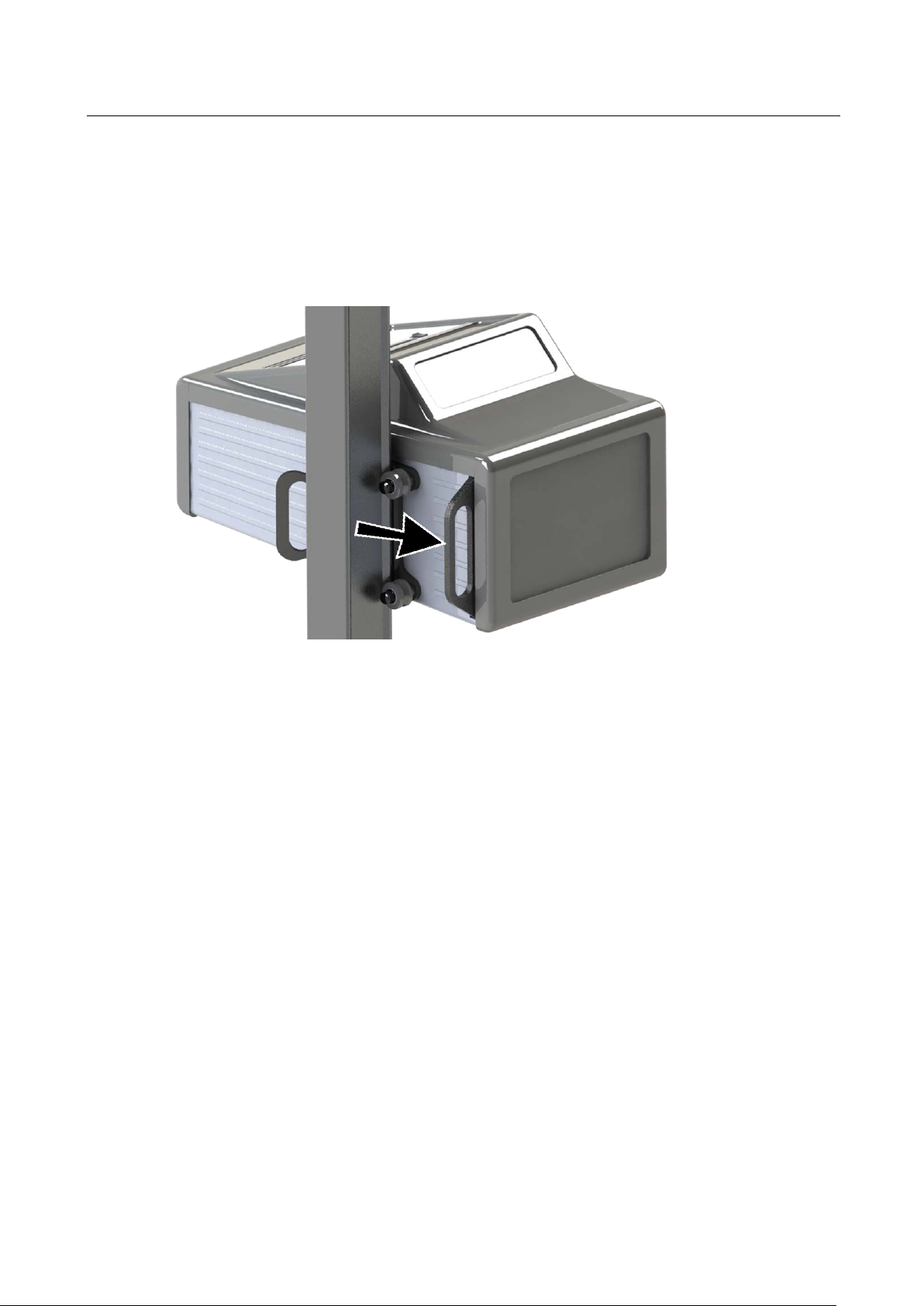
6.1.2
Horizontal Alignment
a
b
Pos: 88 /Produktfamilien/Alle Geräte/Überschriften/Überschriften 1.1.1/H/Überschrift 1.1.1: Horizontale Ausrichtung @ 44\mod_1457362804716_75.docx @ 2417648 @ 3 @ 1
Pos: 89 /Produktfamilien/Scheinwerfereinstellprüftechnik/MLT-SERIES/380801 MLT 1000/380801_001 MLT 1000 MB/BA/Inhalt: 3808_001 Horizonta le Ausrichtung: Fahrwage n einstellen (Te xt) @ 44\mod_145736159 5177_75.doc x @ 2417602 @ @ 1
• Loosen the fixing screw (a) with an Allen key WAF 5.
• Adjust the tappet’s setting screw (b) with an open-ended wrench WAF 27.
• Carefully tighten the setting screw and fixing screw.
• Check that they match the centre cross again.
Pos: 90 /Produktfamilien/Scheinwerfereinstellprüftechnik/MLT-SERIES/380801 MLT 1000/380801_001 MLT 1000 MB/BA/Inhalt: 3808_001 Hori zontale Ausrichtung: Fahrwagen einstelle n (Bild) @ 4 4\mod_1457358754229 _0.docx @ 2417556 @ @ 1
Pos: 91 /-----Format-----/MANUELLER UMBRUCH Seitenumbruch @ 0\mod_1134403577687_0.d ocx @ 1277 @ @ 1
BA380801_001-en
Page 19

19
6.2
Laser Calibration Set
A
D
B
E
C
F
6.3
Laser Positions
1:
2:
3:
Pos: 92 /Produktfamilien/Scheinwerfereinstellprüftechnik/MLT-SERIES/380701 MLT 3000/TH/Inhalt: 3807 Beschreibung Lase rstrahl-Kalibriergerät (Text)_12pt @ 35\mod_1390896177367_75.docx @ 1882823 @ 2 @ 1
Pos: 93 /Produktfamilien/Scheinwerfereinstellprüftechnik/MLT-SERIES/380701 MLT 3000/TH/Inhalt: 3807 Beschreibung Laserstrahl-Kalibriergerät (Bilder) @ 35\mod_1390895612780_0.docx @ 1882779 @ @ 1
Pos: 94 /Produktfamilien/Alle Geräte/Überschriften/Überschriften ohne Nummerierung/Überschrift: Laserpositionen @ 37\mod_1400657749834_75.docx @ 19999 38 @ @ 1
Prism
Battery housing
Adjustment screws
Circle spirit level
Base plate
Alignment rail
Pos: 95 /Produktfamilien/Scheinwerfereinstellprüftechnik/MLT-SERIES/380701 MLT 3000/TH/Inhalt: 3807 Laserpositio nen (Bilder) @ 35\mod_139090082310 2_0.docx @ 18829 11 @ @ 1
X = 0.0 %
Y = 0.0 %
X = +2.0 %
Y = 0.0 %
X = 0.0 %
Y = 2.0 %
BA380801_001-en
Page 20

20
6.4
Checking the Precision of the Laser Calibration Set
Pos: 96 /Produktfamilien/Scheinwerfereinstellprüftechnik/MLT-SERIES/380701 MLT 3000/TH/Inhalt: 3807 Mechanische Just ierung_12pt @ 43\mod_1448609 994612_75.docx @ 2351463 @ @ 1
Precise measurements can only be taken if the measuring station is absolutely
level. The base surface for the vehicle and the light tester must form a horizontal
plane (for tolerances, see below).
The laser beam calibration unit allows the measurement accuracy of the headlight
tester to be checked and corrected as needed on site.
Accuracy of the measuring equipment ....................................................... ±2 mm / 10 m
Permissible unevenness of light tester base surface ......................... max. 1 mm / 1 m
Permissible unevenness of vehicle base surface .....................................................
Pos: 97 /Produktfamilien/Scheinwerfereinstellprüftechnik/MLT-SERIES/380701 MLT 3000/TH/Inhalt: 3807 Überprüfung der Genauigkeit des Laser-Kalibrie rsets_12pt @ 43\mod_1448610 128860_75.do cx @ 2351509 @ 2 @ 1
....................................................... see country-specific road traffic licensing regulations
Never stare into the laser beam. Wear safety goggles. Observe occupational safety and accident prevention regulations for laser radiation.
1 Mount the laser calibration set on the tripod and position it in front of a screen
at a distance of 10 m (± 0.5 cm).
2 Use the spirit level to align the laser unit and then switch on the laser.
3 Rotate the laser 180° around its axis in the basic position in the prism
(position 1, no setting angle).
The laser point on the screen must always remain in the same place and must
not perform any rotation (± 1 mm).
4 Move the laser to position 1 and mark the laser point on the screen.
5 Move the laser to position 2 and mark the new position.
The new laser point (position 2) on the screen must be 20 cm (± 4 mm) to the
right. This corresponds to an angle of 2%.
6 Move the laser back to position 1.
7 Use the adjustment screw to move the laser to position 3.
8 Mark the new laser point on the screen.
The new laser point (position 3) on the screen must be 20 cm (± 4 mm) verti-
cally below the original setting (pos. 1). This corresponds to an angle of 2%.
9 Dismount the laser calibration set.
If the laser point changes position when it rotates around its axis or the distances
between the various positions are different to those specified, the calibration set is
faulty and must not be used for calibration. The calibration set needs to be realigned by the manufacturer.
Pos: 98 /-----Format-----/MANUELLER UMBRUCH Seitenumbruch @ 0\mod_1134403577687_0.docx @ 1277 @ @ 1
BA380801_001-en
Page 21

6.5 Mechanical Inspection
1 Check that the base surfaces of the light tester and the laser tripod are even.
2 Mount the laser calibration set on the tripod and position it opposite the MLT:
insert laser mount with the battery housing (B) into prism (A).
3 Move the laser and prism to position 1 (right endpoint). The prism with the
laser is held in the correct position by the magnet.
4 Check the vertical alignment of the MLT. Apply the spirit level to the lens and
read it.
5 Use adjustment screws (C) and a circle spirit level (D) to align the base plate
so that the laser is horizontal.
6 Check that the lens is aligned parallel to the rail by measuring the distance
between the alignment rail (F) and the lens at two points.
7 Switch on the laser. The laser beam should hit the centre of the Fresnel lens.
21
2
4
BA380801_001-en
Page 22

22
6.6
Adjusting the Pointer Position
Pos: 102 /Produktfamilien/Alle Geräte/Überschriften/Überschriften 1.1/E/Überschrift 1.1: Einstellung der Zeigerposition @ 43\mod_1448611011877_75.docx @ 2351651 @ 2 @ 1
Pos: 103 /Produktfamilien/Scheinwerfereinstellprüftechnik/MLT-SERIES/380801 MLT 1000/380801_001 MLT 1000 MB/BA/Inhalt: 3808_001 Zeigerposit ion einstellen - Deckel (Text) @ 43\mod_1448611939869_75.docx @ 2351933 @ @ 1
• Remove the cover and rear panel from the tester.
• The control panel can also be removed for better accessibility. To do this, re-
Pos: 104 /Produktfamilien/Scheinwerfereinstellprüftechnik/MLT-SERIES/380801 MLT 1000/380801_001 MLT 1000 MB/BA/Inhalt: 3808_001 Zeigerposit ion einstellen - Deckel (Bilder) @ 43\mod_14486113726 56_0.docx @ 2351747 @ @ 1
move the four fillister head screws.
Pos: 105 /-----Format-----/MANUELLER UMBRUCH Seitenumbruch @ 0\mod_1134403 577687_0.do cx @ 1277 @ @ 1
BA380801_001-en
Page 23

23
Pos: 106 /Produktfamilien/Scheinwerfereinstellprüftechnik/MLT-SERIES/380801 MLT 1000/380801_001 MLT 1000 MB/BA/Inhalt: 3808_001 Zeigerposit ion einstellen - Pos. 0 (Text) @ 43\mod_1448612257208_ 75.docx @ 2351979 @ @ 1
• Precisely place the pointer into the zero position.
• The pin must be at a right angle to the endpoint. Loosen the fastening screw
and move the endpoint if necessary. Retighten the fastening screw.
Pos: 107 /Produktfamilien/Scheinwerfereinstellprüftechnik/MLT-SERIES/380801 MLT 1000/380801_001 MLT 1000 MB/BA/Inhalt: 3808_001 Zeige rposition einst ellen - Pos. 0 (Bilder) @ 43\mod_ 1448529305695_0.doc x @ 2350730 @ @ 1
• Check the pointer position again.
Pos: 108 /-----Format-----/MANUELLER UMBRUCH Seitenumbruch @ 0\mod_1134403 577687_0.do cx @ 1277 @ @ 1
BA380801_001-en
Page 24

24
Pos: 109 /Produktfamilien/Scheinwerfereinstellprüftechnik/MLT-SERIES/380801 MLT 1000/380801_001 MLT 1000 MB/BA/Inhalt: 3808_001 Zeigerposit ion einstellen - Pos. 6 (Text) @ 43\mod_1448613042924_ 75.docx @ 2352025 @ @ 1
• Precisely place the pointer into the endpoint position.
• The pin must be at a right angle to the endpoint. Loosen the fastening screw
and move the endpoint if necessary. Retighten the fastening screw.
• Check the pointer position again.
Pos: 110 /Produktfamilien/Scheinwerfereinstellprüftechnik/MLT-SERIES/380801 MLT 1000/380801_001 MLT 1000 MB/BA/Inhalt: 3808_001 Zeigerposit ion einstellen - Pos. 6 (Bilder) @ 43\mod_144853203422 6_0.docx @ 23509 66 @ @ 1
Pos: 111 /-----Format-----/MANUELLER UMBRUCH Seitenumbruch @ 0\mod_1134403 577687_0.do cx @ 1277 @ @ 1
BA380801_001-en
Page 25

25
6.6.1
Adjusting the Projection Area
Pos: 112 /Produktfamilien/Alle Geräte/Überschriften/Überschriften 1.1/E/Überschrift 1.1: Einstellung der Projektionsfläche @ 42\mod_1422958438583_75.docx @ 2196380 @ 3 @ 1
Pos: 113 /Produktfamilien/Scheinwerfereinstellprüftechnik/MLT-SERIES/380801 MLT 1000/380801_001 MLT 1000 MB/BA/Inhalt: 3808_001 Projektions fläche einstellen (Text) @ 43\mod_1448613395049_ 75.docx @ 2352071 @ @ 1
• An assembly opening on the housing is used to adjust the projection area.
• Open the clamping screw, adjust the cable and retighten the screw.
• The laser beam must now match the centre cross on the rear panel of the
Pos: 114 /Produktfamilien/Scheinwerfereinstellprüftechnik/MLT-SERIES/380801 MLT 1000/380801_001 MLT 1000 MB/BA/Inhalt: 3808_001 Projektions fläche einstellen ( Bild) @ 43\mod_1448532706443_ 0.docx @ 2351012 @ @ 1
headlight tester.
Pos: 115 /-----Format-----/MANUELLER UMBRUCH Seitenumbruch @ 0\mod_1134403 577687_0.do cx @ 1277 @ @ 1
BA380801_001-en
Page 26

26
6.6.2
Calibration of the Luminous Intensity
Inaccuracy
Display Range
Calculation
Pos: 116 /Produktfamilien/Alle Geräte/Überschriften/Überschriften 1.1/K/Überschrift 1.1: Kalibrierung der Lichtstärkenmessung @ 42\mod_1423037892015_75.docx @ 2197246 @ 3 @ 1
Pos: 117 /Produktfamilien/Scheinwerfereinstellprüftechnik/MLT-SERIES/380801 MLT 1000/TH/Inhalt: 3808 Kalibrierung der Lichtst ärkenmessung @ 42\mod_ 1423037957453_75.do cx @ 2197452 @ @ 1
Luxmeter: ± 1 lx ≙ approx. 5 %
Test device: Photometer Polytec IL 1400 A ≙ approx. -2 %
High beam: 0 to 64 lx
Low beam: 0 to 2 lx
Lux1: Luminous intensity at the lens in lx (lm/m2)
Lux2: Luminous intensity at screen in lx (lm/m2)
r1: Distance referring to 25 m based on § 50 StVO (German Road Traf-
fic Licensing Regulations)
r2: Distance Lens to Screen = 0.5 m
r
Lux2 = Lux1
r
Pos: 118 /-----Format-----/MANUELLER UMBRUCH Seitenumbruch @ 0\mod_1134403577687_0.d ocx @ 1277 @ @ 1
2
2
2
1
BA380801_001-en
Page 27

27
6.7
Inspection Certificates (Inspection Interval: Annually)
Inspection Certificate
Inspection Certificate
Pos: 119 /Produktfamilien/Alle Geräte/Überschriften/Überschriften 1.1/P/Überschrift 1.1: Prüfbestätigungen (Prüfintervall: jährlich) @ 44\mod_1454317504659_75.docx @ 2389060 @ 2 @ 1
Pos: 120 /Produktfamilien/Scheinwerfereinstellprüftechnik/MLT-SERIES/380801 MLT 1000/380801_001 MLT 1000 MB/BA/Inhalt: 3808_001 Prüfbestät igung @ 43\mod_1448269740327_75. docx @ 2345732 @ @ 1
The following items have been inspected:
• Column fixation ...................................................................................... OK
• Adjustment of projection area at headlight tester .................................... OK
• Accuracy of laser calibration unit ............................................................ OK
• Calibration of light intensity/illuminance measurement ............................ OK
• Adjustment of headlight tester to approach marking .............................. OK
• Adjustment of guide rails ........................................................................ OK
Date Name Signature
Pos: 121 /-----Format-----/MANUELLER UMBRUCH Seitenumbruch @ 0\mod_1134403 577687_0.do cx @ 1277 @ @ 1
BA380801_001-en
Page 28

28
Inspection Certificate
Inspection Certificate
Pos: 122 /Produktfamilien/Scheinwerfereinstellprüftechnik/MLT-SERIES/380801 MLT 1000/380801_001 MLT 1000 MB/BA/Inhalt: 3808_001 Prüfbestät igung @ 43\mod_1448269740327_75. docx @ 2345732 @ @ 1
The following items have been inspected:
• Column fixation ...................................................................................... OK
• Adjustment of projection area at headlight tester .................................... OK
• Accuracy of laser calibration unit ............................................................ OK
• Calibration of light intensity/illuminance measurement ............................ OK
• Adjustment of headlight tester to approach marking .............................. OK
• Adjustment of guide rails ........................................................................ OK
Date Name Signature
Pos: 123 /-----Format-----/MANUELLER UMBRUCH Seitenumbruch @ 0\mod_1134403 577687_0.do cx @ 1277 @ @ 1
BA380801_001-en
Page 29

29
Inspection Certificate
Inspection Certificate
Pos: 124 /Produktfamilien/Scheinwerfereinstellprüftechnik/MLT-SERIES/380801 MLT 1000/380801_001 MLT 1000 MB/BA/Inhalt: 3808_001 Prüfbestät igung @ 43\mod_1448269740327_75. docx @ 2345732 @ @ 1
The following items have been inspected:
• Column fixation ...................................................................................... OK
• Adjustment of projection area at headlight tester .................................... OK
• Accuracy of laser calibration unit ............................................................ OK
• Calibration of light intensity/illuminance measurement ............................ OK
• Adjustment of headlight tester to approach marking .............................. OK
• Adjustment of guide rails ........................................................................ OK
Date Name Signature
Pos: 125 /-----Format-----/MANUELLER UMBRUCH Seitenumbruch @ 0\mod_1134403 577687_0.do cx @ 1277 @ @ 1
BA380801_001-en
Page 30

30
Inspection Certificate
Inspection Certificate
Pos: 126 /Produktfamilien/Scheinwerfereinstellprüftechnik/MLT-SERIES/380801 MLT 1000/380801_001 MLT 1000 MB/BA/Inhalt: 3808_001 Prüfbestät igung @ 43\mod_1448269740327_75. docx @ 2345732 @ @ 1
The following items have been inspected:
• Column fixation ...................................................................................... OK
• Adjustment of projection area at headlight tester .................................... OK
• Accuracy of laser calibration unit ............................................................ OK
• Calibration of light intensity/illuminance measurement ............................ OK
• Adjustment of headlight tester to approach marking .............................. OK
• Adjustment of guide rails ........................................................................ OK
Date Name Signature
Pos: 127 /-----Format-----/MANUELLER UMBRUCH Seitenumbruch @ 0\mod_1134403 577687_0.do cx @ 1277 @ @ 1
BA380801_001-en
Page 31

31
Inspection Certificate
Inspection Certificate
Pos: 128 /Produktfamilien/Scheinwerfereinstellprüftechnik/MLT-SERIES/380801 MLT 1000/380801_001 MLT 1000 MB/BA/Inhalt: 3808_001 Prüfbestät igung @ 43\mod_1448269740327_75. docx @ 2345732 @ @ 1
The following items have been inspected:
• Column fixation ...................................................................................... OK
• Adjustment of projection area at headlight tester .................................... OK
• Accuracy of laser calibration unit ............................................................ OK
• Calibration of light intensity/illuminance measurement ............................ OK
• Adjustment of headlight tester to approach marking .............................. OK
• Adjustment of guide rails ........................................................................ OK
Date Name Signature
Pos: 129 /-----Format-----/MANUELLER UMBRUCH Seitenumbruch @ 0\mod_1134403 577687_0.do cx @ 1277 @ @ 1
BA380801_001-en
Page 32

32
Pos: 130 /Produktfamilien/Alle Geräte/Inhalte/Inhalt: Firmen-Information MAHA @ 53\mod_1529400378770_75.docx @ 3037518 @ @ 1
© MAHA Maschinenbau Haldenwang GmbH & Co. KG
Legal notice based on ISO 16016:
The reproduction, distribution and utilization of this document as well as the communication of its
contents to others without explicit authorization is prohibited. Offenders will be held liable for the
payment of damages. All rights reserved in the event of the grant of a patent, utility model or design.
The contents of this edition have been checked with great care. However, errors cannot be fully
excluded. Subject to technical change without notice.
Document
Document No.: BA380801_001-en
Approval Date: 2019-03-18
Manufacturer
MAHA Maschinenbau Haldenwang GmbH & Co. KG
Hoyen 20
87490 Haldenwang
Germany
Phone: +49 8374 585 0
Fax: +49 8374 585 590
Mail: maha@maha.de
Web: http://www.maha.de
Service
=== Ende der Liste für Textmarke Inhalt ===
MAHA SERVICE CENTER
AutomoTec GmbH
Maybachstraße 8
87437 Kempten
Germany
Phone: +49 8374 585 100
Fax: +49 8374 585 491
Mail: service@automo-tec.com
Web: www.automo-tec.com
BA380801_001-en
Page 33

 Loading...