

Page 1

Fehler! Verwenden Sie die Registerkarte 'Start', um Name dem Text zuzuweisen, der hier angezeigt werden soll.Fehler! Verwenden Sie
die Registerkarte 'Start', um Name dem Text zuzuweisen, der hier angezeigt werden soll.Fehler! Verwenden Sie die Registerkarte
'Start', um Name dem Text zuzuweisen, der hier angezeigt werden soll.
MFP 3000
Driving Test Bench
Original Operating Instructions
BA690101-en
Pos: 1 /Technisc he D okum entat ion/L eis tungsm ess tech nik/ 69 Fa hrpr üfstä nde/0 101 M FP 3000/BA/Inhalt: 6901 Titelbild @ 42\mod_1433333755361_0.docx @ 2250524 @ @ 1
Pos: 2 /-----For mat---- -/MAN UELLER UM BRUCH Sei tenumb ruch @ 0\mod _11 34403 5776 87_0.d ocx @ 127 7 @ @ 1
Page 2

2
BA690101-en
Pos: 3 /-----Forma t-----/Inhaltsverzeichnis - 3 Ebenen @ 5\mo d_1168867441046_75.d ocx @ 72920 @ @ 1
Contents
1 Safety ...................................................................................................................... 5
1.1 Introduction ......................................................................................................................................... 5
1.2 Symbols .............................................................................................................................................. 5
1.3 Intended Use ....................................................................................................................................... 5
1.4 Requirements on Operating and Service Personnel ............................................................................. 5
1.5 Safety Instructions for Commissioning ................................................................................................. 6
1.6 Safety Instructions for Operation ......................................................................................................... 6
1.7 Safety Instructions for Servicing ........................................................................................................... 8
1.8 Safety Instructions for Handling Hydraulic Fluid ................................................................................... 8
1.9 What to Do in the Event of an Accident ............................................................................................... 8
2 Specifications ........................................................................................................... 9
3 Software Operation ................................................................................................ 12
3.1 Home Screen .................................................................................................................................... 12
3.2 User Login ......................................................................................................................................... 13
3.3 Manual Emergency Operation ........................................................................................................... 14
3.4 Settings / Operating Data .................................................................................................................. 15
3.4.1 Settings: Language ........................................................................................................................... 15
3.4.2 Settings: Time Management .............................................................................................................. 15
3.4.3 Settings: Torque Smoothing .............................................................................................................. 16
3.4.4 Settings: Test Duration ...................................................................................................................... 17
3.4.5 Settings: Roller Diameter ................................................................................................................... 17
3.4.6 Settings: Speed Difference at 60 kph ................................................................................................ 17
3.4.7 Switching to the User Management ................................................................................................... 17
3.5 User Management ............................................................................................................................. 18
3.6 Showing Warning and Error Messages .............................................................................................. 20
3.7 Showing Charts ................................................................................................................................. 23
3.8 Showing Equipment Data .................................................................................................................. 24
3.9 Quitting the Program ......................................................................................................................... 25
4 Test Procedure ...................................................................................................... 26
4.1 Switching on ..................................................................................................................................... 26
4.2 Setting the Wheelbase ...................................................................................................................... 26
4.3 Driving onto the Test Bench .............................................................................................................. 26
4.4 Preparing the Test ............................................................................................................................. 27
4.5 Performing the Test ........................................................................................................................... 27
4.6 Using the Tyre Pressure Control ........................................................................................................ 28
4.7 Terminating the Test .......................................................................................................................... 29
4.8 Switching out .................................................................................................................................... 29
5 Maintenance .......................................................................................................... 30
5.1 Annual Inspection .............................................................................................................................. 30
Page 3

3
BA690101-en
5.2 Maintenance Interval ......................................................................................................................... 30
5.3 Care Instructions ............................................................................................................................... 30
5.4 Spare Parts ....................................................................................................................................... 30
6 Service Lifetime ...................................................................................................... 31
7 Dismantling ............................................................................................................ 31
8 Disposal ................................................................................................................. 31
9 Company Information ............................................................................................. 32
Pos: 4 /-----Forma t-----/MANUELLER UMBRUCH Seitenumbruch @ 0\mod_ 1134403577687_0.doc x @ 1277 @ @ 1
Page 4

4
BA690101-en
Pos: 5 /-----Forma t-----/MANUELLER UMBRUCH Seitenumbruch @ 0\mo d_1134403577687_0.do cx @ 1277 @ @ 1
Page 5
5
BA690101-en
Pos: 6 /Technische Dokumentation/Alle Geräte/Überschriften/Überschriften 1/S/Überschrift 1: Sicherheit @ 6\mod_1174482399906_75.docx @ 76962 @ 1 @ 1
1
Safety
Pos: 7 /Technische Dokumentation/Alle Geräte/Überschriften/Überschriften 1.1/E/Überschrift 1.1: Einführung @ 6\mod_1174482219062_75.docx @ 76793 @ 2 @ 1
1.1
Introduction
Pos: 8 /Technische Dokumentation/Alle Geräte/Inhalte/Sicherheit/Inhalt: Einführung Sicherheit_12pt @ 25\mod_1324455248318_75.d ocx @ 1138886 @ @ 1
Thoroughly read this manual before operating the equipment and comply with the
instructions. Always display the manual in a conspicuous location.
Personal injury and property damage incurred due to non-compliance with these
safety instructions are not covered by the product liability regulations.
Pos: 9 /Technische Dokumentation/Leistungsprüfstände, Diagnose-/Abgasgeräte/69 Fahrprüfstände/0101 MFP 3000/BA/Inhalt: 6901 Einführung Sicherheit Zusatzhinweis @ 42\mod_1423213391083_75.docx @ 2198324 @ @ 1
These operating instructions are intended only for the appropriate use of the
driving test bench MFP 3000. For other technical equipment or machines, which
are no direct components of the driving test bench (such as the scissors lift),
please refer to the operating instructions provided with the product.
Pos: 10 /Technische Dokumentation/Alle Geräte/Überschriften/Überschriften 1.1/S/Überschrift 1.1: Symbole @ 6\mod_1174482270875_75.docx @ 76865 @ 2 @ 1
1.2
Symbols
Pos: 11 /Technische Dokumentation/Alle Geräte/Inhalte/Sicherheit/Inhalt: Symbole Sicherheit_12pt @ 25\mod_1324456650897_75.docx @ 1139046 @ @ 1
Important safety instructions. Failure to comply with instructions could result in
personal injury or property damage.
Important information.
Pos: 12 /Technische Dokumentation/Alle Geräte/Überschriften/Überschriften 1.1/B/Überschrift 1.1: Bestimmungsgemäßer Gebrauch @ 6\mod_1176734022203_75.docx @ 88746 @ 2 @ 1
1.3
Intended Use
Pos: 13 /Technische Dokumentation/Leistungsprüfstände, Diagnose-/Abgasgeräte/69 Fahrprüfstände/0101 MFP 3000/BA/Inhalt: 6901 Bestimmungsgemäßer Gebrauch @ 41\mod_1420715724852_75.docx @ 2178925 @ @ 1
The MAHA driving test bench MFP 3000 shall be used exclusively for the direct
functional testing of electronic systems which require a steady and even drive of
the vehicle wheels within the framework of regular vehicle inspections.
The MFP 3000 simulates regular driving conditions and therefore allows system
checks on ABS, ESP, cornering/turning lights, AFS-Emergency stop signal, safety
belt warning, ASR and tyre pressure monitoring (partial check).
The driving test bench shall not be modified without the express written consent of
the manufacturer. In case of non-compliance the declaration of conformity
becomes void.
Pos: 14 /Technische Dokumentation/Alle Geräte/Überschriften/Überschriften 1.1/A/Überschrift 1.1: Anforderungen an das Bedienungs- und Servicepersonal @ 34\mod_1380637497630_75.docx @ 1835413 @ 2 @ 1
1.4
Requirements on Operating and Service Personnel
Pos: 15 /Technische Dokumentation/Alle Geräte/Inhalte/Sicherheit/Inhalt: Anforderungen an das Bedienungs- und Servicepersonal_12pt @ 34\mod_1380637348320_75.docx @ 1835369 @ @ 1
All persons employed in the operation, maintenance, installation, removal and
disposal of the device must
• be at least 18 years old,
• be trained and instructed in writing,
• have read and understood this manual
Page 6

6
BA690101-en
• be on record as having been instructed in safety guidelines.
Pos: 16 /Technische Dokumentation/Alle Geräte/Überschriften/Überschriften 1.1/S/Überschrift 1.1: Sicherheitsvorschriften für die Inbetriebnahme @ 6\mod_1174482269156_75.docx @ 76838 @ 2 @ 1
1.5
Safety Instructions for Commissioning
Pos: 17 /Technische Dokumentation/Leistungsprüfstände, Diagnose-/Abgasgeräte/69 Fahrprüfstände/0101 MFP 3000/BA/Inhalt: 6901 Sicherheitsvorschriften für die Inbetriebnahme @ 41\mod_1420715877339_75.docx @ 2178951 @ @ 1
• The driving test bench shall be installed and commissioned by authorized
service personnel only.
• The driving test bench shall not be installed and commissioned in hazardous
locations, outdoors, in moist rooms (e.g. car wash) or outside a temperature
range of 5…40 °C (41…104 °F).
• The control desk must be positioned so that the operating personnel cannot be
hit by flying particles ejected from the rotating wheels. Otherwise put up a
sufficiently dimensioned protective wall between the operating panel and the
MFP 3000. (Note steering angle of front wheels!)
• Use a 40 amps time-delay fuse for the mains power supply. This is adequate
for the current development stage of the test bench (and lift). To be prepared
for future stages and options, we recommend to use a power supply line
suitable for a fuse protection of up to 63 amps.
• Usage of an RCD should be avoided if possible (risk of undefined triggering!). If
installation of an RCD is mandatory, use a short-time delayed type which is
suitable for frequency converters and requires a minimum trigger current of
300 mA. Other standards and regulations may apply.
Pos: 18 /Technische Dokumentation/Alle Geräte/Überschriften/Überschriften 1.1/S/Überschrift 1.1: Sicherheitsvorschriften für den Betrieb @ 6\mod_1174482268953_75.docx @ 76826 @ 2 @ 1
1.6
Safety Instructions for Operation
Pos: 19 /Technische Dokumentation/Leistungsprüfstände, Diagnose-/Abgasgeräte/69 Fahrprüfstände/0101 MFP 3000/BA/Inhalt: 6901 Sicherheitsvorschriften für den Betrieb @ 41\mod_1420715968504_75.docx @ 2178998 @ @ 1
• The test bench shall be used and operated exclusively for its intended purpose
and only within its performance limits.
• Observe the detailed operating instructions supplied with the DUO CM lift.
• Pay close attention to accident prevention regulations.
• The test bench shall be operated by trained personnel only.
• The test bench shall only be operated by persons who are physically and
mentally fit. These persons must be well rested and not under the influence of
alcohol, drugs or medication.
• When not in use, the system must be switched off and the main switch
protected against re-start.
• No persons shall be in the danger zone while a vehicle is entering, crossing or
exiting the test bench.
• In addition to the danger zone, the operator is responsible for confining the area
of the test room in which no persons are allowed during testing with a safety
catch device or a cell wall. Mark the danger zone (roller width + 1100 mm) on
both sides behind the vehicle up to cell wall/safety catch device.
• Keep the test bench surface clean and dry. Danger of slipping when surface is
wet, oily or icy! Do not place any objects (tools, material etc.) on the test bench.
Wear protective shoes with anti-slip soles and steel toe caps to avoid slipping
Page 7

7
BA690101-en
and mechanical injuries. Parts which protrude more than 20 mm out of the floor
are to be marked with black-yellow tape.
• Do not exceed the rated load capacity of the lift.
• Drive onto the test bench only when it is in a fully lowered position.
• The test bench can be driven over in its retracted position with a maximum
wheel load of 1000 kg. This load corresponds to a vehicle gross weight of
approx. 3500 kg.
• Use a non-slip ladder for entering and leaving the vehicle.
• After switching over the operating mode from "DUO" to "MFP 3000" remove
the key and keep it in a safe place.
• Center the vehicle in the prism of the axle play tester and secure it against
rolling off by pulling on the parking brake.
• During test preparation the inspector must keep a safe distance.
• The vehicle tests must be performed by two persons. One person is at the
control desk, the other in the passenger compartment.
• During the vehicle tests no additional persons are allowed in the test room.
• The emergency stop device must be easily accessible at all times.
• While the rollers are being driven, the inspector must remain in the passenger
compartment and have the emergency device readily at hand.
• Do not step on the roller sets, not even when they are in a locked position.
• Avoid unnecessary strain on vehicle and test bench. Drive the vehicle slowly
onto the test bench.
• Damage to low lying vehicles is not covered by the warranty.
• Regularly check the tightness of the cover plate attachment screws.
• Wear personal protective clothing. If necessary wear protective goggles.
Particles ejected from rotating vehicle wheels can cause severe injuries. Wear
tightly fitting working clothes and bind long hair together. Clothing or hair can
get caught and pulled into machinery.
• Danger of hearing damage due to high noise level! Use hearing protection
approved up to 120 dB(A). Noise levels over 110 dB(A) can be reached during
vehicle testing. The operator is responsible for determining the noise level in
vehicle and test room. When necessary, wear suitable hearing protection. The
operator must attach warning stickers.
• Danger of carbon monoxide poisoning by poisonous vehicle exhaust. The test
stand may only be operated if the room in which the test stand is installed has
sufficient exhaust suction and ventilation including the appropriate warning
system.
• Wait until vehicle and rollers have stopped moving before exiting the vehicle.
Danger of body parts and clothing being pulled into rotating rollers and vehicle
wheels.
Page 8

8
BA690101-en
• Pull on the parking brake before lowering the vehicle from the wheel-free jack
onto the runways to prevent the vehicle from rolling away.
Pos: 20 /Technische Dokumentation/Alle Geräte/Überschriften/Überschriften 1.1/S/Überschrift 1.1: Sicherheitsvorschriften für Servicearbeiten @ 6\mod_1174482270640_75.docx @ 76850 @ 2 @ 1
1.7
Safety Instructions for Servicing
Pos: 21 /Technische Dokumentation/Leistungsprüfstände, Diagnose-/Abgasgeräte/69 Fahrprüfstände/0101 MFP 3000/BA/Inhalt: 6901 Sicherheitsvorschriften für Servicearbeiten @ 39\mod_1409820260713_75.docx @ 2089441 @ @ 1
• Service work must be done by authorized service technicians.
• Turn off the main switch and secure it against being turned on again before
doing any repair, maintenance or setup work.
• DANGER! Electric shock hazard. After switching off all voltages dangerous
voltage can still be present for at least 5 minutes!
• During maintenance work the system must be depressurized.
• Ensure that ecologically harmful substances are disposed of in accordance with
the appropriate regulations.
• Use caution when cleaning the equipment: system is under pressure!
• Do not use high pressure or steam jet cleaners. Do not use caustic cleaning
agents.
• The safety devices must be set by authorized service technicians.
• Do not replace or override the safety devices.
Pos: 22 /Technische Dokumentation/Alle Geräte/Überschriften/Überschriften 1.1/S/Überschrift 1.1: Sicherheitsvorschriften für den Umgang mit Hydrauliköl @ 16\mod_1246607729523_75.docx @ 401284 @ 2 @ 1
1.8
Safety Instructions for Handling Hydraulic Fluid
Pos: 23 /Technische Dokumentation/Alle Geräte/Inhalte/Sicherheit/Inhalt: Sicherheitsvorschriften für den Umgang mit Hydrauliköl_12pt @ 25\mod_1324456399127_75.docx @ 1139012 @ @ 1
• Neutralize hydraulic fluid spills with binder.
• Remove contaminated clothing immediately.
• Inhalation: If symptoms persist, seek medical treatment.
• Skin contact: Wash skin immediately with soap and water. If skin irritation
persists, seek immediate medical advice.
• Eye contact: Rinse thoroughly with water and seek medical advice.
• Ingestion: Do not induce vomiting. Seek immediate medical attention.
Pos: 24 /Technische Dokumentation/Alle Geräte/Überschriften/Überschriften 1.1/V/Überschrift 1.1: Verhalten bei Unfällen @ 19\mod_1267177245337_75.docx @ 794600 @ 2 @ 1
1.9
What to Do in the Event of an Accident
Pos: 25 /Technische Dokumentation/Alle Geräte/Inhalte/Sicherheit/Inhalt: Verhalten bei Unfällen_12pt @ 34\mod_1381128863435_75.docx @ 1837175 @ @ 1
• The injured person is to be removed from the danger area. Find out where
dressing and bandages are kept. Seek first-aid.
• Provide first-aid (stop bleeding, immobilise injured limbs), report the accident
and seal off the accident site.
• Immediately report any accident to your supervisor. Make sure a record is kept
of every occasion first-aid is provided, e.g. in an accident book.
• Remain calm and answer any questions that may arise.
Pos: 26 /-----Format-----/MANUELLER UMBRUCH Seitenumbruch @ 0\mod_11344035 77687_0.doc x @ 1277 @ @ 1
Page 9
9
BA690101-en
Pos: 27 /Technische Dokumentation/Alle Geräte/Überschriften/Überschriften 1/T/Überschrift 1: Technische Daten @ 6\mod_1174482473078_75.docx @ 76986 @ 1 @ 1
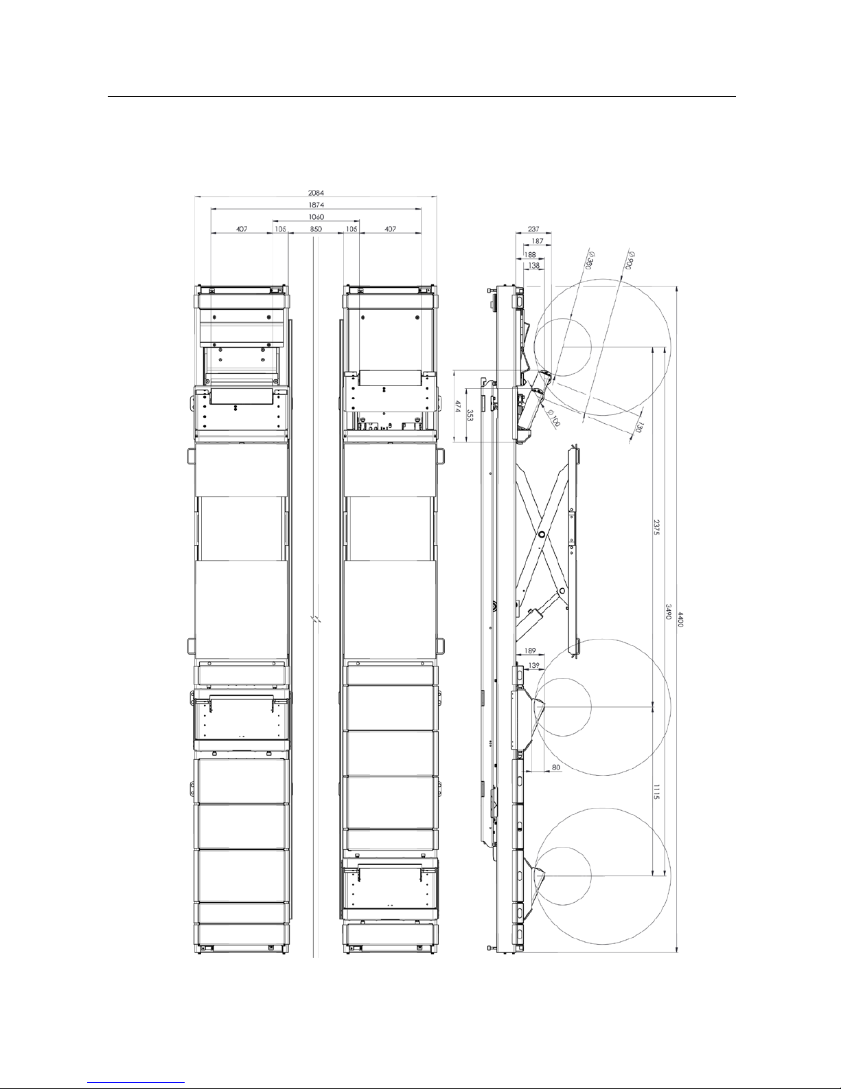
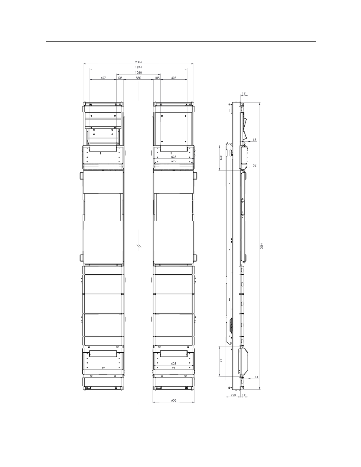
2
Specifications
Pos: 28 /Technische Dokumentation/Leistungsprüfstände, Diagnose-/Abgasgeräte/69 Fahrprüfstände/0101 MFP 3000/BA/Inhalt: 6901 Technische Daten (Bilder) @ 42\mod_1423827664850_0.docx @ 2200884 @ @ 1
10
Page 10
10
BA690101-en
Pos: 29 /-----Format-----/MANUELLER UMBRUCH Seitenumbruch @ 0\mod_11344035 77687_0.doc x @ 1277 @ @ 1
Page 11
11
BA690101-en
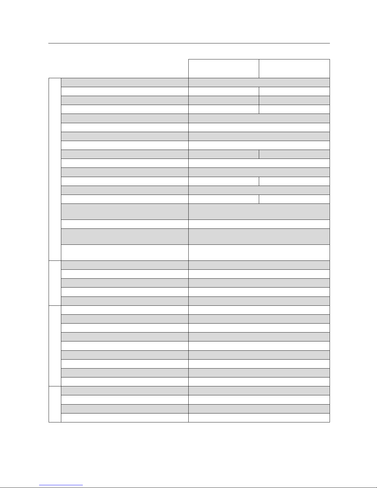
Pos: 30 /Technische Dokumentation/Leistungsprüfstände, Diagnose-/Abgasgeräte/69 Fahrprüfstände/0101 MFP 3000/BA/Inhalt: 6901 Technische Daten (Tabelle) @ 45\mod_1468233140301_75.docx @ 2537508 @ @ 1
MFP 3000
(Front axle)
MFP 3000
(Rear axle)
Test bench
Working pressure 100 bar
Width (FA / RA) 633 mm 628 mm
Height (FA / RA) 111 mm 111 mm
Length (FA / RA) 391 mm 461 mm
Axle distance (min. / max.) 2375 mm / 3490 mm
Track width with 850 mm installation width 1200 mm / 1600 mm
Steering angle ± 15°
Contact pressure 30 kg
Weight 2 x 65 kg 2 x 55 kg
Weight of hydraulic unit (runway) 2 x 40 kg
Load capacity 3500 kg
Full travel 130 mm 80 mm
Lifting time typical
Drive-over height with compensation plates 58 mm 61 mm
Friction coefficient of test roller/tyre (depending
on tyre model)
approx. 0.9
Noise emission (without vehicle)
< 80 dB
Possible wheel diameters
R10…R24
(min. axle distances limited by wheel diameter)
Possible function tests (depending on vehicle
status)
ABS; ESP; Cornering light; ASR;
RDK (Tyre pressure monitoring; indirectly)
Motor
Diameter / Width 100 mm / 470 mm
Rated power 2.5 kW
Rated torque (Maximum torque) 7.5 Nm (15 Nm)
Maximum speed (Master-Slave) 70 kph (80 kph)
RPM (at 80 km/h) 4244 1/min
Electronics
Fuse (time-delay) 40 A
Control cabinet (height / width / depth) 1300 mm / 1200 mm / 400 mm
Control cabinet weight 170 kg
Temperature range (operation / storage) 5…30 °C / -15…30 °C
Cable length (lift control cabinet) 10 m
Mains frequency 50 Hz
Mains voltage 400 V
Phases 3
Rated power 27.0 kW
Overall
Hydraulic power unit (lift) 5.5 kW
Working temperature range 5…40 °C
Shipping weight preinstalled on lift
Shipping dimensions (height / width / length) preinstalled on lift
Pos: 31 /-----Format-----/MANUELLER UMBRUCH Seitenumbruch @ 0\mod_11344035 77687_0.docx @ 1277 @ @ 1
Page 12

12
BA690101-en
Pos: 32 /Technische Dokumentation/Alle Geräte/Überschriften/Überschriften 1/S/Überschrift 1: Software-Bedienung @ 30\mod_1352733596033_75.docx @ 1675567 @ 1 @ 1
3
Software Operation
Pos: 33 /Technische Dokumentation/Leistungsprüfstände, Diagnose-/Abgasgeräte/69 Fahrprüfstände/0101 MFP 3000/BA/Abschnitt: 6901 Startbildsc hirm @ 42\mod_1432626240374_75. docx @ 2246038 @ 2 @ 1
3.1
Home Screen
Manual emergency operation
Reset control
Settings/Operating data
Increase speed by 10 kph
Go to "Login" screen
(for service technicians only)
Reduce speed by 10 kph,
master-slave operation
Quit program
Extend MFP 3000
Show warning/error messages
Retract MFP 3000
Show diagrams
Stop drives
Back to home screen
Acknowledge warning/error
message
Display of target speed
Start drives
Display of master-slave
operation
Logout/Login
Enable tyre pressure control,
rear left
Enable tyre pressure control, rear
right
Enable tyre pressure control,
front left
Enable tyre pressure control,
front right
Pos: 34 /-----Format-----/MANUELLER UMBRUCH Seitenumbruch @ 0\mod_11344035 77687_0.docx @ 1277 @ @ 1
Page 13

13
BA690101-en
Pos: 35 /Technische Dokumentation/Leistungsprüfstände, Diagnose-/Abgasgeräte/69 Fahrprüfstände/0101 MFP 3000/BA/Abschnitt: 6901 Benutzeranmeld ung @ 42\mod_1422448795002_ 75.docx @ 2192251 @ 2 @ 1
3.2
User Login
1 Touch any button except for and .
The login dialog appears.
2 Enter the user password and confirm with "OK".
The user logged in is displayed in the top left-hand corner of the screen. The
driving test bench is ready for operation.
Pos: 36 /-----Format-----/MANUELLER UMBRUCH Seitenumbruch @ 0\mod_11344035 77687_0.docx @ 1277 @ @ 1
Page 14
14
BA690101-en
Pos: 37 /Technische Dokumentation/Leistungsprüfstände, Diagnose-/Abgasgeräte/69 Fahrprüfstände/0101 MFP 3000/BA/Abschnitt: 6901 Handnotbet rieb @ 42 \mod_1423554388345_ 75.docx @ 2199234 @ 2 @ 1
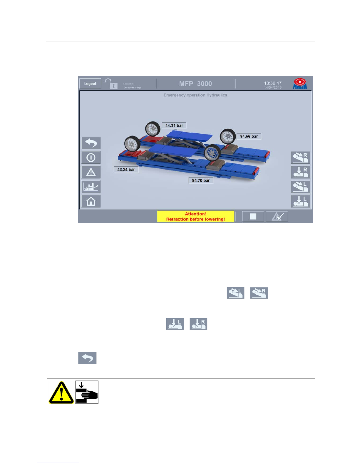
3.3
Manual Emergency Operation
Rear axle
In the event of control or hydraulic system failure the driving test bench is
depressurised at the rear axle and is lowered by its own weight.
Front axle
In the event of a system failure the front axle can be manually lowered into bottom
position.
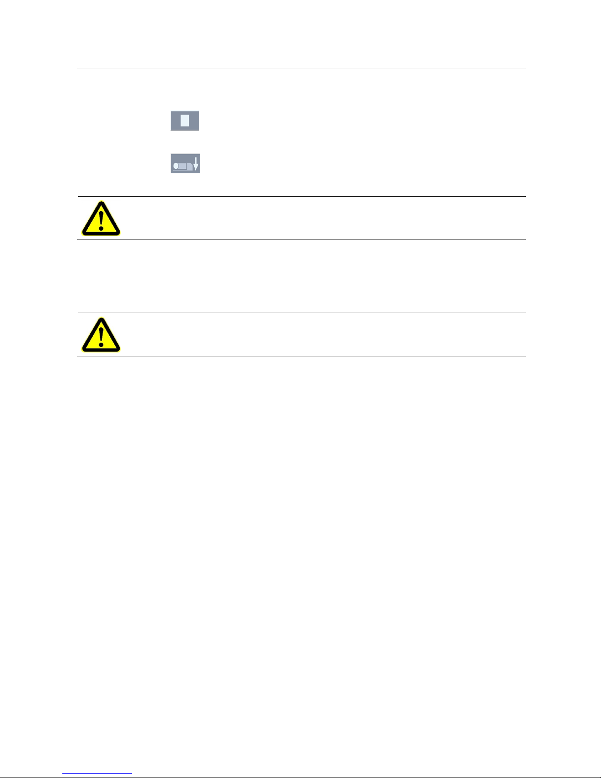
1 When a pressure value is displayed, push Button / . When "0 bar"
is displayed, hold down the button and retract the driving test bench with
muscle power.
2 After retraction push button / and lower the driving test bench
using a mechanical tool, e.g. a rod.
Back to previous screen
Pos: 38 /Technische Dokumentation/Leistungsprüfstände, Diagnose-/Abgasgeräte/69 Fahrprüfstände/0101 MFP 3000/BA/Inhalt: 6901 Info - Vorsicht Quetschgefahr @ 42\mod_1423483102925_75.docx @ 2198986 @ @ 1
Crushing hazard!
Pos: 39 /-----Format-----/MANUELLER UMBRUCH Seitenumbruch @ 0\mod_11344035 77687_0.docx @ 1277 @ @ 1
Page 15

15
BA690101-en
Pos: 40 /Technische Dokumentation/Leistungsprüfstände, Diagnose-/Abgasgeräte/69 Fahrprüfstände/0101 MFP 3000/BA/Abschnitt: 6901 Einstellungen / Betriebsdaten @ 42\mod_1429515053718_75.docx @ 2231174 @ 23333333 @ 1
3.4
Settings / Operating Data
Go to user management screen (admin password required)
Back to previous screen
Connect desktop PC to control unit
Disconnect desktop PC from control unit
3.4.1
Settings: Language
1 Choose the desired language from the selection menu.
3.4.2
Settings: Time Management
Disabling summer/winter time:
1 Touch button <Disable summer/winter time>.
Summer/winter time change is disabled.
Page 16

16
BA690101-en
Enabling summer/winter time:
1 Touch button <Enable summer/winter time>.
2 Make your settings in the dialog
menu.
3 Confirm with <OK>.
Setting the Time Zone:
1 Choose the desired time zone from
the selection menu.
Setting the Time:
1 Touch the white field.
2 Enter date and time.
3 Confirm with ENTER.
4 Push button .
Data transfer to control unit.
3.4.3
Settings: Torque Smoothing
1 Touch the white field.
2 Enter the desired value.
3 Confirm with ENTER.
The graph in the diagram will be smoothed.
Page 17

17
BA690101-en
3.4.4
Settings: Test Duration
1 Touch the white field.
2 Set the test duration (10…60 min).
3 Conform with ENTER.
Data transfer to control unit.
3.4.5
Settings: Roller Diameter
1 Touch the white field.
2 Set the roller diameter (0.098…0.102 m).
3 Conform with ENTER.
Data transfer to control unit.
3.4.6
Settings: Speed Difference at 60 kph
1 Touch the white field.
2 Set the speed difference (0…10 kph).
3 Conform with ENTER.
Data transfer to control unit.
3.4.7
Switching to the User Management
1 Push button .
The login dialog appears:
2 Enter the administrator password. (Password is chosen by service technician at
initial operation.)
3 Confirm with OK.
Button is displayed in green.
4 Touch button .
The User Management appears.
Pos: 41 /-----Format-----/MANUELLER UMBRUCH Seitenumbruch @ 0\mod_11344035 77687_0.docx @ 1277 @ @ 1
Page 18

18
BA690101-en
Pos: 42 /Technische Dokumentation/Leistungsprüfstände, Diagnose-/Abgasgeräte/69 Fahrprüfstände/0101 MFP 3000/BA/Abschnitt: 6901 Benutzerverwaltung @ 42\mod_1422449674981_ 75.docx @ 2192838 @ 2 @ 1
3.5
User Management
Creating a User Account
1 Touch the empty line in column <Users>.
2 Enter the user name (10 characters max.), confirm with ENTER.
Page 19

19
BA690101-en
3 Touch the line containing the new user in column <Password>. Enter and
repeat password and confirm with <OK>.
4 Touch the line containing the new user in column <Group>. Choose a group (=
access level) and confirm with ENTER.
The group members have the following rights:
<Administrator group>: user management
<User group>: operation of the driving test bench
<Unauthorised>: no rights
5 Touch the line containing the new user in column <Logout time>. Enter a time
period (60 min max.) and confirm with ENTER.
The logout time should be chosen depending on the test cycle used. It should be
defined as short as possible to prevent unauthorised access during absence of
the user.
6 Push button .
Pos: 43 /-----Format-----/MANUELLER UMBRUCH Seitenumbruch @ 0\mod_11344035 77687_0.docx @ 1277 @ @ 1
Page 20

20
BA690101-en
Pos: 44 /Technische Dokumentation/Leistungsprüfstände, Diagnose-/Abgasgeräte/69 Fahrprüfstände/0101 MFP 3000/BA/Abschnitt: 6901 Warn- und Störmeldungen einblenden @ 42\mod_ 1422450250425_75.doc x @ 2192885 @ 2 @ 1
3.6
Showing Warning and Error Messages
As long as the list of all pending warning and error messages is displayed, the
buttons are disabled.
Choose a message text from the list by clicking it with the left mouse button.
Touch button . The help text appears.
Pos: 45 /Technische Dokumentation/Leistungsprüfstände, Diagnose-/Abgasgeräte/69 Fahrprüfstände/0101 MFP 3000/BA/Inhalt: 6901 Warn- und Störmeldungen (Tabelle) @ 39\mod_1409820261337_75.docx @ 2089582 @ @ 1
List of Warning and Error Messages
No.
Message
1 EMERGENCY STOP triggered!
2 Error! Pressure transducer RL: Wire breakage!
3 Error! Pressure transducer RR: Wire breakage!
4 Error! Pressure transducer FL: Wire breakage!
5 Error! Pressure transducer FR: Wire breakage!
6 Error! Distance wheel/limit switch RL too wide or no vehicle on the test bench!
7 Error! Distance wheel/limit switch RR too wide or no vehicle on the test bench!
8 Error! Distance wheel/limit switch FL too wide or no vehicle on the test bench!
9 Error! Distance wheel/limit switch FR too wide or no vehicle on the test bench!
10 Error! Overpressure RL!
11 Error! Overpressure RR!
Page 21

21
BA690101-en
No.
Message
12 Error! Overpressure FL!
13 Error! Overpressure FR!
14 Error! Hydraulic unit or limit switch RL "Retracted" defective!
15 Error! Hydraulic unit or limit switch RR "Retracted" defective!
16 Error! Hydraulic unit extending cylinder or limit switch FL "Retracted" defective!
17 Error! Hydraulic unit extending cylinder or limit switch FR "Retracted" defective!
18 Error! Hydraulic unit raising cylinder or limit switch FL "Extended" defective!
19 Error! Hydraulic unit raising cylinder or limit switch FR "Extended" defective!
20 Error! Hydraulic unit raising cylinder or limit switch FL "Retracted" defective!
21 Error! Hydraulic unit raising cylinder or limit switch FR "Retracted" defective!
22 Error! Pressure RL too low!
23 Error! Pressure RR too low!
24 Error! Pressure FL too low!
25 Error! Pressure FR too low!
26 Error! Operating unit error or connection error with operating unit!
27 Error! Drive error RL!
28 Error! Drive error RR!
29 Error! Drive error FL!
30 Error! Drive error FR!
31 Error! Frequency converter (supply) error!
32 Error! Hydraulic motor error!
33 Error! Hydraulic motor: contactor contacts welded!
34 Error! Lift not in bottom position or limit switch "+A-B8 DUO CM in bottom position" defective!
48 Warning! Lift not in bottom position!
35
Error! Hydraulic cylinder RL in lower end position! Hydraulic unit or limit switch RL "Retracted"
defective!
36
Error! Hydraulic cylinder RR in lower end position! Hydraulic unit or limit switch RR "Retracted"
defective!
37
Error! Hydraulic cylinder FL in lower end position! Hydraulic unit or limit switch FL "Retracted"
defective!
38
Error! Hydraulic cylinder FR in lower end position! Hydraulic unit or limit switch FR "Retracted"
defective!
39 Error! Converter: control unit error!
Page 22

22
BA690101-en
No.
Message
40 Error! Drive RL: Maximum permissible speed exceeded!
41 Error! Drive RR: Maximum permissible speed exceeded!
42 Error! Drive FL: Maximum permissible speed exceeded!
43 Error! Drive FR: Maximum permissible speed exceeded!
44 Error! Switch on control voltage EMERGENCY STOP!
45 Error! MFP 3000 FL not in bottom position!
46 Error! MFP 3000 FR not in bottom position!
47 Error! MFP 3000 RL not in bottom position!
48 Error! MFP 3000 RL not in bottom position!
If frequency converter errors occur, additional messages are displayed.
Pos: 46 /-----Format-----/MANUELLER UMBRUCH Seitenumbruch @ 0\mod_11344035 77687_0.docx @ 1277 @ @ 1
Page 23

23
BA690101-en
Pos: 47 /Technische Dokumentation/Leistungsprüfstände, Diagnose-/Abgasgeräte/69 Fahrprüfstände/0101 MFP 3000/BA/Abschnitt: 6901 Diagramme einblenden @ 42\mod_1422450592049_75.docx @ 2192949 @ 2 @ 1
3.7
Showing Charts
Chart showing the speed values (y-axis left side) and torque values (y-axis right
side). The table below the chart shows the numerical values.
Choose button to switch between the axes.
Start Explorer
Print screen (printer required)
Start Snipping Tool
Pos: 48 /-----Format-----/MANUELLER UMBRUCH Seitenumbruch @ 0\mod_11344035 77687_0.docx @ 1277 @ @ 1
movable
Page 24

24
BA690101-en
Pos: 49 /Technische Dokumentation/Leistungsprüfstände, Diagnose-/Abgasgeräte/69 Fahrprüfstände/0101 MFP 3000/BA/Abschnitt: 6901 Anlagendaten anzeigen @ 45\mod_1468223734133_75.docx @ 2537178 @ 2 @ 1
3.8
Showing Equipment Data
In the home screen, touch button .
In the <Equipment data> screen, touch button .
Input box <Daily password> appears.
Enter Daily password – <Operating hours counter> appears.
Pos: 50 /-----Format-----/MANUELLER UM BRUCH Seitenumbruch @ 0\mod_1134403577687_0. docx @ 1277 @ @ 1
Page 25

25
BA690101-en
Pos: 51 /Technische Dokumentation/Leistungsprüfstände, Diagnose-/Abgasgeräte/69 Fahrprüfstände/0101 MFP 3000/BA/Abschnitt: 6901 Programm beende n @ 42\mod_1429516906649_ 75.docx @ 2231221 @ 2 @ 1
3.9
Quitting the Program
To quit the program, confirm the request with <OK>.
The computer is shut down.
Pos: 52 /-----Format-----/MANUELLER UMBRUCH Seitenumbruch @ 0\mod_11344035 77687_0.docx @ 1277 @ @ 1
Page 26

26
BA690101-en
Pos: 53 /Technische Dokumentation/Alle Geräte/Überschriften/Überschriften 1/P/Überschrift 1: Prüfablauf @ 7\mod_1193228570533_75.docx @ 128778 @ 1 @ 1
4
Test Procedure
Pos: 54 /Technische Dokumentation/Leistungsprüfstände, Diagnose-/Abgasgeräte/69 Fahrprüfstände/0101 MFP 3000/BA/Inhalt: 6901 Prüfablauf @ 42\mod_1429516981092_75.docx @ 2231268 @ 22222222 @ 1
4.1
Switching on
1 Main switch ON.
2 EMERGENCY STOP control voltage ON.
3 Wait until the software is ready for operation.
The vehicle tests must be performed by two persons. One person is at the
control desk, the other in the passenger compartment.
4.2
Setting the Wheelbase
1 Measure the wheelbase at the vehicle.
2 Set the wheelbase at the test bench. This should be in bottom position and set
so that the top of the raised rear wheel hangs free directly between roller and
drive-over plate.
3 Position the compensating plates at the rear axle. There are adjusting screws
with rubber buffers at the base frame of the test bench. These must be set so
that the clearance between test bench and compensating plates is free of play.
The hydraulic hoses and electric cables must be routed through the cutouts in the
compensating plates. Risk of damage!
4.3
Driving onto the Test Bench
Lift, wheel-free jack and driving test bench are in bottom position.
1 Turn the selector switch to position "DUO".
2 Briefly touch button "LIFT UP"; the prism of the axle play tester is extended.
3 Center the vehicle on the axle play tester.
Page 27

27
BA690101-en
4 Slide the wheel-free jack extensions as required, so that the test bench and
wheel-free jack are not damaged while raising the vehicle.
5 Briefly raise the vehicle with the wheel-free jack, place support blocks
underneath. The wheels of FA and RA must no longer contact the rollers, the
wheels of the FA should be a maximum of 70 mm above the prism.
6 Turn the selector switch to "MFP 3000" and remove the key.
4.4
Preparing the Test
1 Push button , the hydraulic unit is extended. is flashing green.
2 Verify that only the four test rollers contact the vehicle wheels.
4.5
Performing the Test
Danger! Risk of death or severe injuries by rotating test bench rollers!
•
Always
keep body parts and clothing away from rotating rollers, as there is
danger of these being caught and pulled in!
•
Do not
leave the keys in the key switch during normal test operation.
• The emergency stop device must be freely accessible at all times.
Risk of hearing damage due to high noise level!
• Use ear protection which is approved for up to 120 dB(A). Noise levels of over
100 dB(A) are possible during vehicle testing.
1 Start the engine, engage a gear, test ASR, shift into "Neutral".
2 Push .
The drives are switched on, a countdown timer (preset test duration) begins
running.
3 Enter the target speed using button or .
4 Perform the tests: ABS, ESP, cornering/turning lights, AFS-Emergency stop
signal, safety belt warning and ASR. The tests can be repeated as often as is
required.
40 seconds before the end of test duration the target speed is automatically
regulated to 0 kph, the countdown time is displayed red, the drives are
gradually decelerated to 0 kph via a speed ramp and finally stopped. The
hydraulic units remain extended, button flashes green. To restart, use
button .
The total runtime of the drives is adjustable under <Various tasks>.
Page 28

28
BA690101-en
While the vehicle is being accelerated to target speed, make sure there are no
activities that could result in a deceleration of the wheels!
Master-Slave Mode
5 After switching on the drives (see step 2), touch button .
The master-slave mode is indicated .
6 Engage a gear (with automatic transmission shift to <D>, with rear-drive
vehicles slowly release the parking brake), gradually accelerate, perform a trial
run.
Sudden accelerating or braking can result in drive errors!
4.6
Using the Tyre Pressure Control
1 Start the engine, shift into "Neutral".
2 Push .
The drives are switched on, a countdown timer (preset test duration) begins
running.
3 Select , , or .
The active button lights green.
4 Enter the target speed (60 kph) using button or .
A message regarding tyre pressure control appears after approx. 100 seconds
at the vehicle cockpit.
5 Enter target speed (0 km/h) using button .
6 When the actual speed is 0 km/h, terminate the test.
To repeat the test with another wheel, the tyre pressure control must be reinitialised at the vehicle!
Page 29
29
BA690101-en
4.7
Terminating the Test
1 Push .
The drives are slowly stopped via a speed ramp.
2 Push .
The driving test bench lowers into bottom position.
The sliding device at the rear wheel must be fixed.
3 Engage first gear (automatic transmission: P) and pull on the parking brake.
4 Turn the selector switch to "DUO".
5 Lower the vehicle with the wheel-free jack until the support blocks can be
removed.
Make sure the extensions of the wheel-free jack do not contact the driving test
bench. Risk of damage!
6 Slide the wheel-free jack extensions as required, so that the test bench and
wheel-free jack are not damaged while lowering the vehicle..
7 Fully lower the wheel-free jack.
8 Release the parking brake and drive the vehicle off the test bench.
4.8
Switching out
1 Quit the program.
2 Turn off the main switch.
Pos: 55 /-----Format-----/MANUELLER UMBRUCH Seitenumbruch @ 0\mod_11344035 77687_0.docx @ 1277 @ @ 1
Page 30

30
BA690101-en
Pos: 56 /Technische Dokumentation/Alle Geräte/Überschriften/Überschriften 1/I/Überschrift 1: Instandhaltung @ 28\mod_1332159812536_75.docx @ 1565908 @ 1 @ 1
5
Maintenance
Pos: 57 /Technische Dokumentation/Alle Geräte/Überschriften/Überschriften 1.1/J/Überschrift 1.1: Jährliche Überprüfung @ 28\mod_1332230089694_75.docx @ 1566204 @ 2 @ 1
5.1
Annual Inspection
Pos: 58 /Technische Dokumentation/Alle Geräte/Inhalte/Info!/Inhalt: Info - Jährliche Überprüfung_12pt @ 25\mod_1324460481075_75.doc x @ 1139412 @ @ 1
• The maintenance interval prescribed by the manufacturer is
12 (twelve) months
.
This maintenance interval refers to normal workshop usage. If the equipment is
used more frequently or under severe operating conditions (e.g. outdoors), the
interval must be reduced accordingly.
• Maintenance work shall be done only by authorized and trained service
technicians provided by the manufacturer, licensed dealers or service partners.
• In case of non-compliance the manufacturer's warranty becomes void.
Pos: 59 /Technische Dokumentation/Hebetechnik/Archiv/00 HBZ Alle/Inhalt: Info - BGR 500 / BGG 945 Jährliche Überprüfung_12pt @ 26\mod_1325586289563_75.docx @ 1145661 @ @ 1
Pos: 60 /Technische Dokumentation/Alle Geräte/Überschriften/Überschriften 1.1/W/Überschrift 1.1: Wartungsintervall @ 34\mod_1381940583161_75.docx @ 1843235 @ 2 @ 1
5.2
Maintenance Interval
Pos: 61 /Technische Dokumentation/Leistungsprüfstände, Diagnose-/Abgasgeräte/69 Fahrprüfstände/0101 MFP 3000/BA/Inhalt: 6901 Wartungsintervall @ 39\mod_1409820261539_75.docx @ 2089629 @ @ 1
After 500 operating hours a warning message appears. Contact the service to
perform the required maintenance work.
Pos: 62 /Technische Dokumentation/Alle Geräte/Überschriften/Überschriften 1.1/P/Überschrift 1.1: Pflegehinweise @ 15\mod_1245912234854_75.docx @ 395780 @ 2 @ 1
5.3
Care Instructions
Pos: 63 /Technische Dokumentation/Alle Geräte/Inhalte/Inhalt: Pflegehinweise - Alle Geräte_12pt @ 26\mod_1324468886116_75.docx @ 1141252 @ @ 1
• Periodically clean the equipment and treat it with a care product.
• Repair damage to the paintwork immediately to prevent corrosion.
• Usage of caustic cleaning agents or high pressure and steam jet cleaners may
lead to equipment damage.
Pos: 64 /Technische Dokumentation/Alle Geräte/Inhalte/Info!/Inhalt: Info - Pflegehinweise_12pt @ 26\mod_1324461215655_75.docx @ 1139602 @ @ 1
Regular care and maintenance is the key condition for functionality and long life
expectancy of the equipment!
Pos: 65 /Technische Dokumentation/Alle Geräte/Überschriften/Überschriften 1.1/E/Überschrift 1.1: Ersatzteile @ 18\mod_1255596847002_75.docx @ 474414 @ 2 @ 1
5.4
Spare Parts
Pos: 66 /Technische Dokumentation/Alle Geräte/Inhalte/Inhalt: Ersatzteile - Alle Geräte_12pt @ 26\mod_1324468768120_75.docx @ 1141219 @ @ 1
To ensure safe and reliable operation, only use original spare parts supplied by the
equipment manufacturer.
Pos: 67 /-----Format-----/MANUELLER UMBRUCH Seitenumbruch @ 0\mod_11344035 77687_0.docx @ 1277 @ @ 1
Page 31

31
BA690101-en
Pos: 68 /Technische Dokumentation/Alle Geräte/Überschriften/Überschriften 1/L/Überschrift 1: Lebensdauer @ 19\mod_1266336761550_75.docx @ 742423 @ 1 @ 1
6
Service Lifetime
Pos: 69 /Technische Dokumentation/Hebetechnik/00 HBZ Alle/Inhalte/Inhalt: Lebensdauer HBZ_12pt @ 26\mod_1325656335645_75.docx @ 1146173 @ @ 1
In its standard version, this product is designed for 22,000 load cycles based on
EN 1493. The maximum period of normal use in relation to the possible product
life expectancy shall be evaluated and scheduled by a qualified person during the
annual safety inspection.
Pos: 70 /Technische Dokumentation/Alle Geräte/Überschriften/Überschriften 1/D/Überschrift 1: Demontage @ 19\mod_1266336822863_75.docx @ 742452 @ 1 @ 1
7
Dismantling
Pos: 71 /Technische Dokumentation/Alle Geräte/Inhalte/Inhalt: Demontage - Alle Geräte_12pt @ 26\mod_1324466078229_75.docx @ 1140857 @ @ 1
Decommissioning and dismantling of the equipment may be done only by
specially authorized and trained personnel provided by the manufacturer, licensed
dealers or service partners.
Pos: 72 /Technische Dokumentation/Alle Geräte/Überschriften/Überschriften 1/G/Überschrift 1: Geräteentsorgung @ 6\mod_1174482271625_75.docx @ 76901 @ 1 @ 1
8
Disposal
Pos: 73 /Technische Dokumentation/Alle Geräte/Inhalte/Inhalt: Geräteentsorgung durch Betreiber allg_12pt @ 26\mod_1324467874153_75.docx @ 1140955 @ @ 1
Pay attention to the product and safety data sheets of the lubricant used. Avoid
damage to the environment. Should a disposal of the device be necessary it must
be done in adherence with locally applicable legal regulations regarding
environmental protection. Remove all materials properly sorted out and bring them
to a suitable waste disposal service. Collect operating materials such as grease,
oils, coolant, solvent-based cleaning fluids etc. in suitable containers and dispose
of in an environmentally protective manner.
Pos: 74 /Technische Dokumentation/Alle Geräte/Inhalte/Inhalt: Geräteentsorgung über Fachbetrieb (alternativ)_12pt @ 26\mod_1324468120852_75.docx @ 1141022 @ @ 1
Alternatively, you may take the equipment to a specialised waste management
plant to ensure that all components and operating liquids are properly disposed
of.
Pos: 75 /-----Format-----/MANUELLER UMBRUCH Seitenumbruch @ 0\mod_11344035 77687_0.docx @ 1277 @ @ 1
Page 32

32
BA690101-en
Pos: 76 /Technische Dokumentation/Alle Geräte/Überschriften/Überschriften 1/F/Überschrift 1: Firmen-Information @ 7\mod_1187338625828_75.docx @ 104047 @ 1 @ 1
9
Company Information
Pos: 77 /Technische Dokumentation/Alle Geräte/Inhalte/Inhalt: Firmen-Information MAHA @ 42\mod_1422267670099_75.docx @ 2188049 @ @ 1
© MAHA Maschinenbau Haldenwang GmbH & Co. KG
Legal notice based on ISO 16016:
The reproduction, distribution and utilization of this document as well as the communication of its
contents to others without explicit authorization is prohibited. Offenders will be held liable for the
payment of damages. All rights reserved in the event of the grant of a patent, utility model or
design.
The contents of this edition have been checked with great care. However, errors cannot be fully
excluded. Subject to technical change without notice.
Document
Document No.: BA690101-en
Approval Date: 2015-09-28
Manufacturer
MAHA Maschinenbau Haldenwang GmbH & Co. KG
Hoyen 20
87490 Haldenwang
Germany
Phone: +49 (0)8374 585 0
Fax: +49 (0)8374 585 499
Fax Parts: +49 (0)8374 585 565
Internet: http://www.maha.de
E-Mail: maha@maha.de
Hotline: +49 (0)1806 624 260 for Brake Testers and Test Lanes
+49 (0)1806 624 280 for Automotive Lifts
+49 (0)1806 624 290 for Dynamometers and Emission Testers
Service
AutomoTec GmbH
Maybachstraße 8
87437 Kempten
Germany
Phone: +49 (0)1806 624 250
Fax: +49 (0)1806 624 255
Internet: http://www.automo-tec.com
E-Mail: service@automo-tec.com
=== Ende der Liste für Textmarke Inhalt ===
 Loading...