

Page 1
MCL
Mobile Column Lift
Original Operating Instructions
BA491201-en
Pos: 1 /Technische Dokumentation/Hebetechnik/ COLUMNLIFT/491201 MCL/BA/I nhalt: 4912 Titelbil d @ 42\mod_1431953418540_0.d ocx @ 2243757 @ @ 1
Pos: 2 /-----Format-----/MANUELLER UMBRUCH Seitenumbr uch @ 0\mo d_1134403577687_0.d
Pos: 2 /-----Format-----/MANUELLER UMBRUCH Seitenumbruc h @ 0\mod_1134403577687_0.d ocx @ 1277 @ @ 1
Fehler! Verwenden Sie die Registerkarte 'Start', um Name dem Text zuzuweisen, der hier angezeigt werden soll.Fehler! Verwenden Sie
die Registerkarte 'Start', um Name dem Text zuzuweisen, der hier angezeigt werden soll.Fehler! Verwenden Sie die Registerkarte
'Start', um Name dem Text zuzuweisen, der hier angezeigt werden soll.
Page 2

2
Pos: 3 /-----For mat---- -/Inh altsv er zeic hn is - 3 Ebe nen @ 5\mod _116 88674 41046_ 75.d ocx @ 72 920 @ @ 1
Contents
1 Safety ...................................................................................................................... 4
1.1 Introduction ......................................................................................................................................... 4
1.2 Symbols .............................................................................................................................................. 4
1.3 Intended Use ....................................................................................................................................... 4
1.4 Inappropriate Use ................................................................................................................................ 4
1.5 Requirements on Operating and Service Personnel ............................................................................. 4
1.6 Safety Instructions for Commissioning ................................................................................................. 5
1.7 Safety Instructions for Operation ......................................................................................................... 5
1.8 Safety Instructions for Servicing ........................................................................................................... 5
1.9 What to Do in the Event of Defects or Malfunctions ............................................................................. 5
1.10 What to Do in the Event of an Accident ............................................................................................... 6
1.11 Safety Features ................................................................................................................................... 6
1.11.1 Locking Device .................................................................................................................................... 6
1.11.2 Braking Motor ..................................................................................................................................... 6
1.11.3 Thermal Overload Protection ............................................................................................................... 6
1.11.4 Safety Shutdown after Motor Overload ................................................................................................ 6
1.11.5 Warning and Information Labels .......................................................................................................... 6
2 Description ............................................................................................................... 7
2.1 Design and Operating Principle ........................................................................................................... 7
2.2 Specifications ...................................................................................................................................... 8
2.3 Sample Nameplate .............................................................................................................................. 9
2.4 Noise Emission .................................................................................................................................... 9
3 Operation ............................................................................................................... 10
3.1 Handling / Moving the Columns ........................................................................................................ 10
3.2 Initial Operation ................................................................................................................................. 11
3.3 Main Switch....................................................................................................................................... 11
3.4 Control Unit ....................................................................................................................................... 12
3.5 Positioning, Logging in and Interconnecting the Columns ................................................................. 14
3.6 Switching over to Group Mode .......................................................................................................... 15
3.7 Switching over to Single Mode .......................................................................................................... 15
3.8 Raising and Lowering ........................................................................................................................ 15
3.9 Shutdown .......................................................................................................................................... 16
3.10 Emergency-down Function, Mechanical ............................................................................................ 16
3.11 Transverse Beam for Semitrailers ...................................................................................................... 17
4 Maintenance .......................................................................................................... 18
4.1 Annual Inspection .............................................................................................................................. 18
4.2 Care Instructions ............................................................................................................................... 18
4.3 Spare Parts ....................................................................................................................................... 18
4.4 Maintenance by the Operator ............................................................................................................ 19
4.4.1 Checking the Load Nut for Wear ....................................................................................................... 19
BA491201-en
Page 3

3
4.4.2 Greasing the Load Nut ...................................................................................................................... 20
4.4.3 Greasing the Support Bearing of the Lifting Screw and the Moving Gear .......................................... 21
4.5 Setting the Hydraulic Jack ................................................................................................................. 22
5 Troubleshooting ..................................................................................................... 23
6 Service Lifetime ...................................................................................................... 24
7 Dismantling ............................................................................................................ 24
8 Disposal ................................................................................................................. 24
9 Contents of the Declaration of Conformity .............................................................. 24
10 Company Information ............................................................................................. 25
Pos: 4 /-----For mat---- -/MAN UELLER UMBRUCH S eitenumb ruch @ 0\m od_11 34403 5776 87_0.d ocx @ 1 277 @ @ 1
BA491201-en
Page 4
4
1
Safety
1.1
Introduction
1.2
Symbols
1.3
Intended Use
1.4
Inappropriate Use
1.5
Requirements on Operating and Service Personnel
Pos: 5 /Technische D okumen tation/A lle Ger äte/ Überschr iften/ Übersc hriften 1/S/Üb erschrift 1: Sich erheit @ 6\mod_1174482399906_75.docx @ 76962 @ 1 @ 1
Pos: 6 /Technisc he Dokum enta tion/ All e Gerä te/ Übers chrif ten/Üb ersc hrift en 1 .1/E/ Übers chr ift 1.1: E inführ ung @ 6\m od_1174482219062_75.docx @ 76793 @ 2 @ 1
Pos: 7 /Techn ische Dokum en tati on/All e Gerä te/I nhal te/S icher heit/I nha lt: Ei nführ ung Sicher hei t @ 6\mod_1175609639562_75.docx @ 87528 @ @ 1
Thoroughly read this manual before operating the equipment and comply with the instructions.
Always display the manual in a conspicuous location.
Personal injury and property damage incurred due to non-compliance with these safety
Pos: 8 /Technische D okumen tation/A lle Ger äte/ Überschr iften/ Übersc hriften 1.1/S/ Überschr ift 1.1: Symbo le @ 6\mod_1174482270875_75.docx @ 76865 @ 2 @ 1
Pos: 9 /Technische D okumen tation/A lle Ger äte/In halte/S icherhe it/Inha lt: Sym bole Sicher heit @ 14\mod_1239866667866_75.docx @ 361518 @ @ 1
instructions are not covered by the product liability regulations.
Important safety instructions. Failure to comply with instructions could result in personal injury or
property damage.
Important information.
Pos: 10 /Technische Dokument ation/Alle Gerät e/Übersc hriften/Üb erschriften 1. 1/B/Übers chrift 1.1: Bestimm ungsgemä ßer Gebrauch @ 6\mod_117 673 402 2203_ 75.doc x @ 8874 6 @ 2 @ 1
Pos: 11 /Technische Dokume ntatio n/Hebet echnik /49 Rad greifer -Hebebü hnen/0 001 Rad greifer -Hebeb ühnen A lle/Inh alte/I nhalt: Bestimm ungs gemäßer Gebra uch RG -HBZ @ 11\mod_1227608538981_75.docx @ 275048 @ @ 1
• This lift is to be used exclusively for the safe lifting of commercial and agricultural vehicles such
as trucks, buses, tractors etc. Observe the rated load capacity.
• The lift may not be modified without the express written consent of the manufacturer. In case of
Pos: 12 /Technische Dokument ation/Alle Gerät e/Übersc hriften/Üb erschriften 1. 1/B/Übers chrift 1.1: Bestimm ungswid riger Gebrauc h @ 18\mod_1255530265027_75.docx @ 471571 @ 2 @ 1
Pos: 13 /Technische Dokume ntatio n/Hebet echnik /00 HBZ Alle/I nhalte/I nhalt: Best immungsw idrig er Gebr auch H BZ @ 19\mod_1267188702628_75.docx @ 794843 @ @ 1
non-compliance the declaration of conformity becomes void.
Any use other than described is inappropriate, for example:
• Climbing on the lift supports
• Transporting persons on the lift supports
Pos: 14 /Technische Dokume ntatio n/Alle Geräte/ Übersc hriften/ Überschr iften 1.1/A/ Übersc hrift 1.1: Anf order ungen a n das Bedien ungs- und Ser vicepers onal @ 34\mod_1380637497630_75.docx @ 1835413 @ 2 @ 1
Pos: 15 /Technische Dokume ntatio n/Alle Geräte/ Inhalte/ Sicher heit/In halt: Anf order ungen a n das Bedie nungs- und Servicep ersonal @ 35\mod_1390296255225_75.docx @ 1 876 648 @ @ 1
• Usage as mobile work platform or for other lifting operations
All persons employed in the operation, maintenance, installation, removal and disposal of the
device must
• be at least 18 years old,
• be trained and instructed in writing,
• have read and understood this manual
• be on record as having been instructed in safety guidelines.
Pos: 16 /Technische Dokume ntatio n/Alle Geräte/ Übersc hriften/ Überschr iften 1.1/S/ Übersc hrift 1.1: Sic herheit svorschr iften f ür di e Inbe triebnahm e @ 6\m od_1174482269156_75.docx @ 76838 @ 2 @ 1
BA491201-en
Page 5

5
1.6
Safety Instructions for Commissioning
1.7
Safety Instructions for Operation
1.8
Safety Instructions for Servicing
1.9
What to Do in the Event of Defects or Malfunctions
Pos: 17 /Technische Dokume ntatio n/Hebet echnik /49 Rad greifer -Hebebü hnen/0 001 Rad greifer -Hebeb ühnen A lle/Inh alte/I nhalt: Sicher heitsvors chrif ten für d ie I nbetrieb nahme RG-H BZ @ 6\ mod_1178094134921_75.docx @ 90757 @ @ 1
• Use the lift on a hard, level surface only.
• The standard lift version may not be installed and commissioned in the vicinity of explosives or
Pos: 18 /Technische Dokument ation/Alle Gerät e/Übersc hriften/Üb erschriften 1. 1/S/Übersc hrift 1.1: Sicherhe itsvorschr iften f ür den Betri eb @ 6\m od_1174482268953_75.docx @ 76826 @ 2 @ 1
Pos: 19 /Technische Dokume ntatio n/Hebet echnik /49 Rad greifer -Hebebü hnen/0 001 Rad greifer -Hebeb ühnen A lle/Inh alte/I nhalt: Sicher heitsvorschriften für den Betrieb RG-HBZ @ 6\mod_1178094657921_75.docx @ 90770 @ @ 1
flammable liquids.
• Read the detailed operating manual.
• Lift operation by trained personnel over 18 years only.
• Do not exceed the rated load capacity per column as indicated on the lift nameplate.
• Ensure an unobstructed movement of lift and vehicle.
• After raising the vehicle briefly, stop and check the lift supports for secure contact with the
vehicle.
• Closely watch lift and vehicle during raising and lowering cycles.
• The working area which cannot be overviewed by the operator should be monitored by a
second person.
• When operating the lift in single or group mode, make sure the vehicle is not tilted.
• Do not allow anyone to stay in lift area during raising and lowering cycles.
• Do not allow anyone to climb on lift or inside raised vehicle.
• Keep lift and vehicle free of tools and parts.
• When using the lift outdoors, lower the vehicle and stop operation when the wind velocity
exceeds 6 m/s.
• Push the support forks completely under the wheels or lift points of the vehicle to be raised.
Pos: 20 /Technische Dokume ntatio n/Alle Geräte/ Übersc hriften/ Überschr iften 1.1/S/ Übersc hrift 1.1: Sic herheit svorschr iften f ür Serv icearbe iten @ 6\mod_1174482270640_75.docx @ 76850 @ 2 @ 1
• Do not drive over or pinch electrical cables.
Pos: 21 /Technische Dokume ntatio n/Hebet echnik /49 Rad greifer -Hebebü hnen/0 001 Rad greifer -Hebeb ühnen A lle/Inh alte/I nhalt: Sicher heitsvors chrif ten für Servic earbei ten RG-H BZ @ 6\mod_1178095227937_75.docx @ 90793 @ @ 1
• Service work may be done by authorized service technicians only.
• Turn off and padlock the main switch before doing any repair, maintenance or setup work.
• Disconnect the mains plug before opening the control box.
• Work on the electrical equipment may be done by service technicians or certified electricians
only.
• Ensure that ecologically harmful substances are disposed of only in accordance with the
appropriate regulations.
• Do not use high pressure or steam jet cleaners. Use of caustic cleaning agents may damage
the lift.
Pos: 22 /Technische Dokument ation/Alle Gerät e/Übersc hriften/Üb erschriften 1. 1/V/Übersc hrift 1.1: Verhal ten im Störfall @ 6\mod_1178097008375_75.docx @ 90829 @ 2 @ 1
Pos: 23 /Technische Dokume ntatio n/Hebet echnik /00 HBZ Alle/I nhalte/I nhalt: Verha lten im Störfal l HBZ @ 19\mod_1267177095494_75.docx @ 794570 @ @ 1
• Do not replace or override the lift safety devices.
• In case of defects or malfunctions such as uncontrolled lift movement or deformation of the
superstructure, support or lower the lift immediately.
• Turn off the main switch and secure it against unauthorized usage. Contact service.
BA491201-en
Page 6
6
1.10
What to Do in the Event of an Accident
1.11
Safety Features
1.11.1
Locking Device
1.11.2
Braking Motor
1.11.3
Thermal Overload Protection
1.11.4
Safety Shutdown after Motor Overload
≥ 15 %
1.11.5
Warning and Information Labels
Pos: 24 /Technische Dokume ntatio n/Alle Geräte/ Übersc hriften/ Überschr iften 1.1/V /Übersc hrift 1 .1: Ver halten bei U nfällen @ 19\m od_12 67177 2453 37_7 5.docx @ 79460 0 @ 2 @ 1
Pos: 25 /Technische Dokument ation/Alle Gerät e/Inhalte/ Sicherhe it/Inhalt: Verha lten bei Unfälle n @ 34\mod_1381128804654_75.docx @ 1837123 @ @ 1
• The injured person is to be removed from the danger area. Find out where dressing and
bandages are kept. Seek first-aid.
• Provide first-aid (stop bleeding, immobilise injured limbs), report the accident and seal off the
accident site.
• Immediately report any accident to your supervisor. Make sure a record is kept of every
occasion first-aid is provided, e.g. in an accident book.
Pos: 26 /Technische Dokume ntatio n/Alle Geräte/ Übersc hriften/ Übers chrifte n 1.1/S/Üb erschr ift 1.1: Sic herheit seinric htunge n @ 6\mod_ 11744 83324 765_7 5.doc x @ 77103 @ 2 @ 1
Pos: 27 /Technische Dokume ntatio n/Hebet echnik /49 Rad greifer -Hebebü hnen/1 901 RG A/BA/In halt: 4 919 Si cher heitseinri chtu ngen @ 22\mod _12 93003 89421 9_75.d ocx @ 95 9625 @ 33 333 @ 1
• Remain calm and answer any questions that may arise.
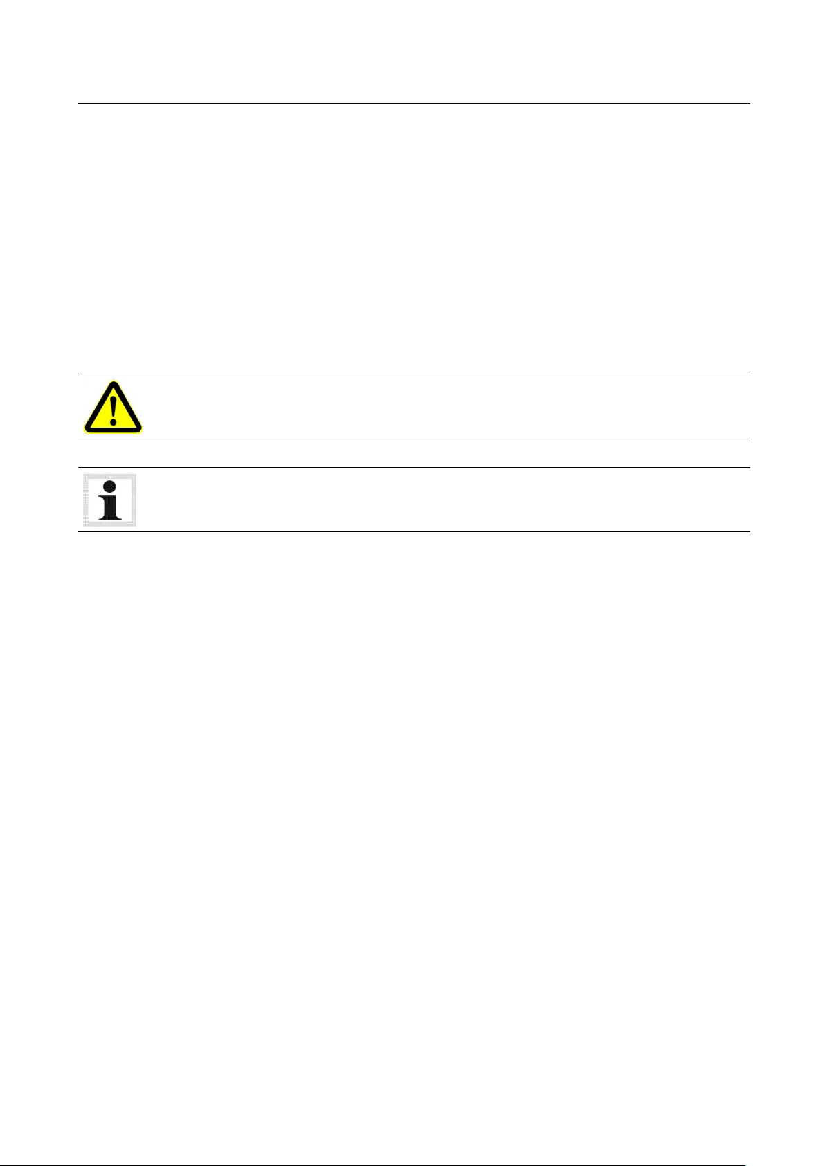
The locking device serves to prevent inadvertent lowering motions caused by gear,
load nut or lifting screw failure. The carriage is blocked by safety wedge (1) and
counterwedge (2).
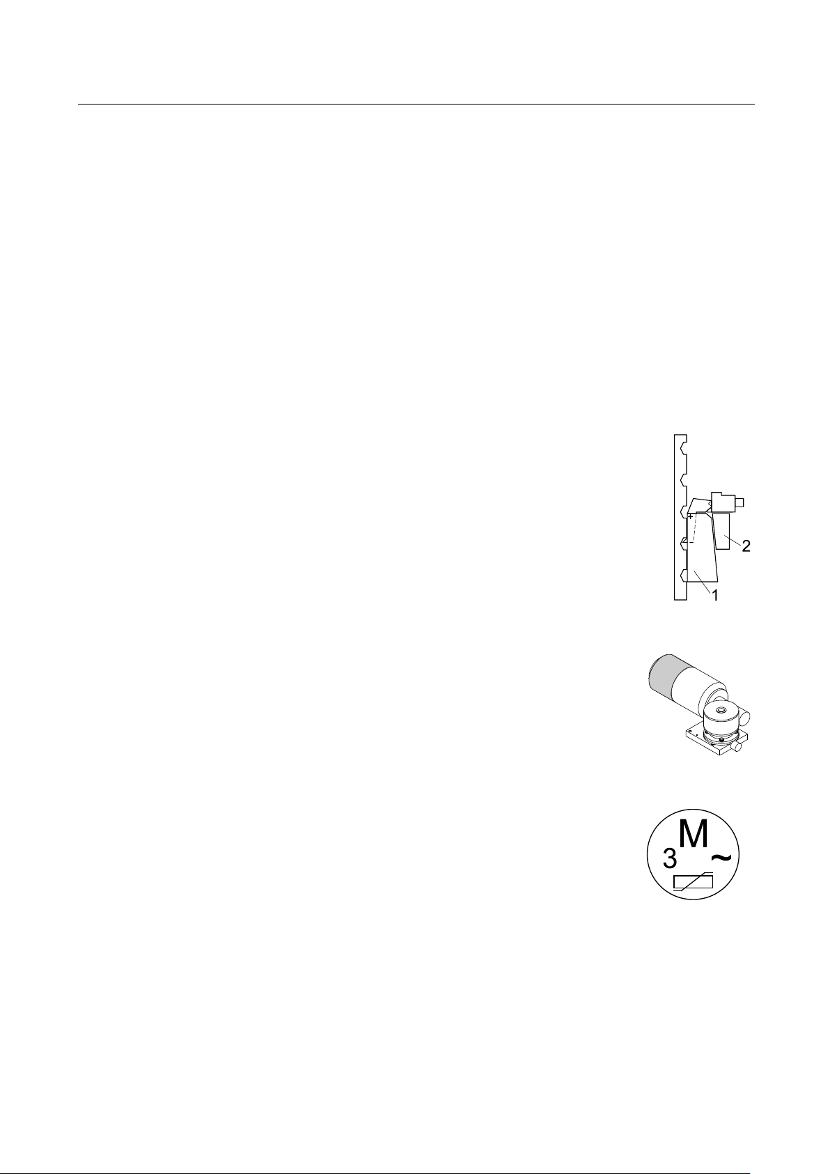
The motors are equipped with AC spring pressure brakes. Once the motors
are switched off, the brakes prevent any further movements.
Overload protection via electronically monitored thermoswitches.
The motor load is permanently monitored by the control PCB. If an overload of
system will switch off automatically. In this case the lift cannot be raised any more, but it can be
normally lowered to bottom position.
Do not change or remove the warning and information labels. Order replacement for defective
Pos: 28 /-----For ma t-----/MA N UEL LER UMB RUC H Se ite num br uch @ 0\m od_1134403577687_0.docx @ 1277 @ @ 1
BA491201-en
labels.
occurs, the
Page 7
7
2
Description
2.1
Design and Operating Principle
Complete System
Column
Control
Pos: 29 /Technische Dokument ation/Alle Gerät e/Übersc hriften/Üb erschriften 1/ B/Überschri ft 1: Beschreibun g @ 6\mod_ 117 4482271453_75.docx @ 76889 @ 1 @ 1
Pos: 30 /Technische Dokume ntatio n/Alle Geräte/ Übersc hriften/ Überschr iften 1.1/A/ Übersc hrift 1.1: Aufb au u nd Arbei tsprinz ip @ 15\mod_1245311386403_75.docx @ 390861 @ 2 @ 1
Pos: 31 /Technisch e Dok ument ation/H ebetech nik/4 9 R adgre ifer-Heb ebü hnen/ 1201 MCL/ BA/I nha lt: 49 12 A ufbau+ Ar beitspr inz ip MCL/ RG B/RGA @ 1 1\mod_1227616300679_75.docx @ 275388 @ @ 1
•
The complete system of the Mobile Column Lift consists of individual columns, which can be
interconnected (e.g. 4, 6, 8 columns) and used to raise commercial vehicles. A maximum number
of 8 columns per lift system can be logically interconnected.
A maximum number of 8 lift systems can be operated parallel, with information exchange on
different radio channels.
The complete system can be operated from each individual column. The columns interact via radio
communication, with each lift system using its own channel.
•
The columns are mechanically designed for engaging the wheels of commercial vehicles.
They are all identical and interchangeable from system to system. Power supply is effected via a
standard three-phase connection.
•
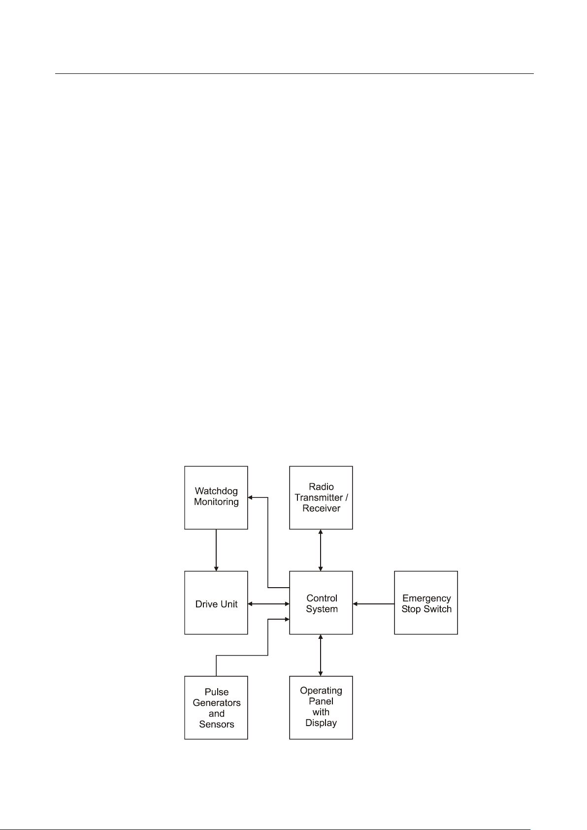
Each column is equipped with a control unit made up of the following components:
• Operating panel with display
• Microprocessor
• Pulse generators and sensors
• Watchdog monitoring
Pos: 32 /Technische Dokume ntatio n/Hebet echnik /49 Rad greifer -Hebebü hnen/1 201 MCL/BA/Inhalt: 4912 Steuerungsschema MCL/RGB/RGA @ 11\mod_1227620776698_75.docx @ 275412 @ @ 1
• Radio transmitter / receiver
• Drive unit
• Emergency stop switch
Pos: 33 /-----For ma t-----/MA N UEL LER UMB RUC H Se ite num br uch @ 0\m od_1134403577687_0.docx @ 1277 @ @ 1
BA491201-en
Page 8
8
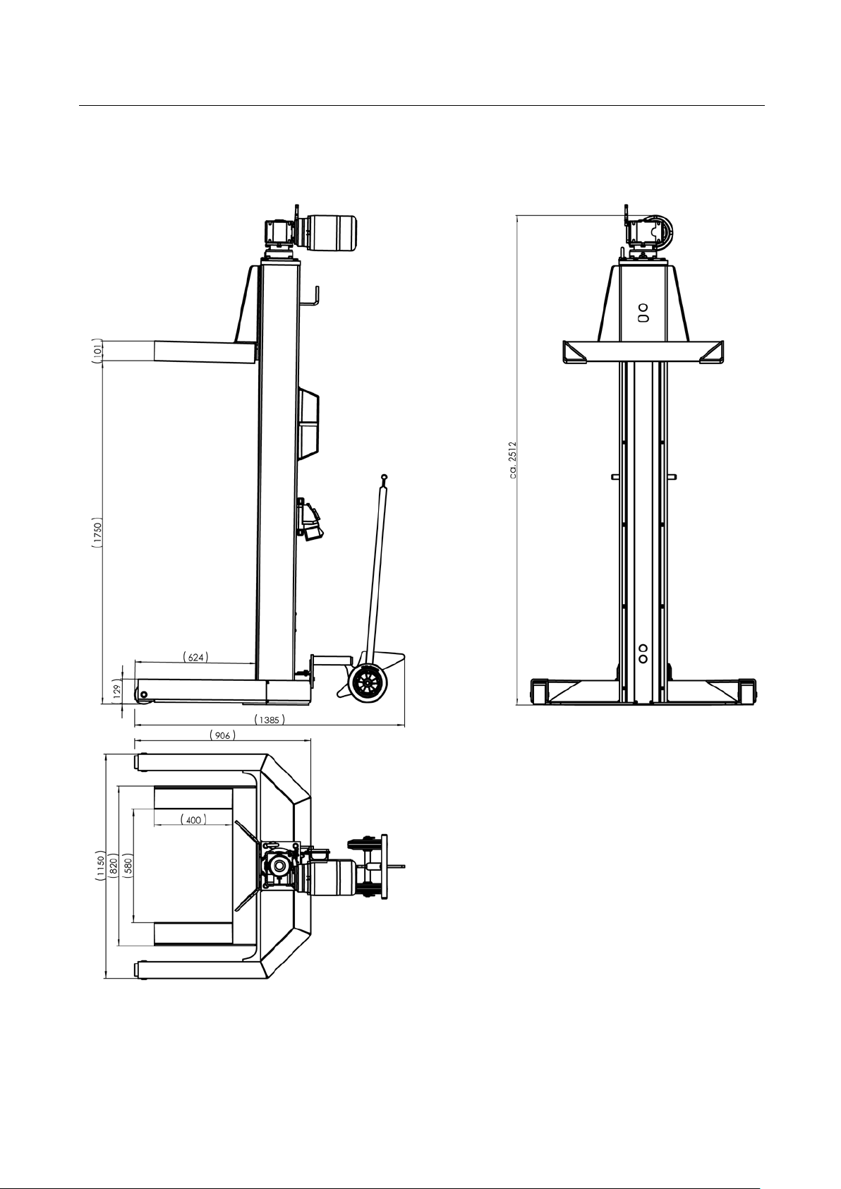
2.2
Specifications
MCL/RGB
Pos: 34 /Techn ische Dokume ntation/Al le Geräte/Übers chriften/ Überschrifte n 1.1/T/Über schrift 1.1: Technische Daten @ 7\mod_1184075526343_75.docx @ 99711 @ 2 @ 1
Pos: 35 /-----For ma t-----/MA NUEL LER UM BRUC H Zeile nscha ltun g @ 7\mod_ 1195 138 965 731_ 0.d ocx @ 13217 7 @ @ 1
Pos: 36 /Technische Dokume ntatio n/Hebet echnik /49 Rad greifer -Hebeb ühn en/1 201 M CL/BA/ Inha lt: 491 2 Tec hnisch e Da ten ( Bild) MC L/RG B @ 18\mod_1256044517960_0.docx @ 480313 @ @ 1
Pos: 37 /-----For mat-----/MAN UE LLE R UM BR UCH Se iten umb ru ch @ 0\mod_1134403577687_0.docx @ 1277 @ @ 1
BA491201-en
Page 9

9
MCL / RGB
2.3
Sample Nameplate
2.4
Noise Emission
Pos: 38 /Technische Dokume ntatio n/Hebet echnik /49 Rad greifer-H ebebü hnen/1 201 MC L/BA/I nhalt: 4912 Tec hnisch e Da ten (Tab elle) MC L / RGB @ 1 8\mod_1256047314854_75.docx @ 480393 @ @ 1
Load capacity per column 5500 kg
Full travel 1750 mm
Raising / Lowering time 150 s
Tyre diameter 900…1250 mm
Fuse protection per column 5 A
Motor power 2.2 kW
Protective system IP 54
Supply voltage 3~ 380/220 V; 50 Hz
Net weight per column 400 kg
Surface load 0.3 N/mm2
Pos: 39 /Technische Dokume ntatio n/Hebet echnik /00 HBZ Alle/ In halte/I nfo!/ Inha lt: I nfo - Betrieb sw armer Zusta nd / Tec hn. Ä nder unge n H BZ @ 6\m od_1177427042703_75.docx @ 90160 @ @ 1
The properties indicated apply to lifts running at operating temperature.
Specifications are subject to change without notice.
Pos: 40 /Technische Dokument ation/Alle Gerät e/Übersc hriften/Üb erschriften 1. 1/T/Übers chrift 1.1: Type nschild-Mus ter @ 1 1\mod _122 76222 06096_ 75.d ocx @ 27 5574 @ 2 @ 1
Pos: 41 /Technische Dokume ntatio n/Hebet echnik /49 Rad greifer -Hebebü hnen/0 001 Rad greifer -Hebeb ühnen A lle/Inh alte/In halt: Ty pensch ild-M uster RG-H BZ M AHA @ 2 4\mod_1309945137131_75.docx @ 1021484 @ @ 1
MOBILE COLUMN LIFT
Ser.No. / Date of Production: ***
Project: ***
Type: ***
Charging Voltage: ***
Operating Voltage: ***
Net weight per column: ***
Load capacity per column: ***
System of Protection: ***
WEEE Reg. No. ***
Pos: 42 /Technische Dokument ation/Alle Gerät e/Übersc hriften/Üb erschriften 1. 1/L/Übers chrift 1.1: Lärmem ission @ 13\mod_ 123 67672 72078_ 75.do cx @ 354 579 @ 2 @ 1
Pos: 43 /Technische Dokume ntatio n/Hebet echnik /00 HBZ Alle/I nhalte/I nhalt: Scha lldruckp egel < 70 d B(A) @ 14\mod_1241593887290_75.docx @ 371013 @ @ 1
Pos: 44 /-----For ma t-----/MA N UEL LER UMB RUC H Se ite num br uch @ 0\m od_1134403577687_0.docx @ 1277 @ @ 1
The sound pressure level is lower than 70 dB(A) in the working area of the operator.
BA491201-en
Page 10

10
3
Operation
3.1
Handling / Moving the Columns
Pos: 45 /Technische Dokument ation/Alle Gerät e/Übersc hriften/Üb erschriften 1/ B/Überschri ft 1: Bedienu ng @ 6\mod_1174482271218_75.docx @ 76877 @ 1 @ 1
Pos: 46 /Technische Dokume ntatio n/Alle Geräte/ Übersc hriften/ Überschr iften 1.1/T/ Übers chrift 1.1: Tra nsport / Vers chiebe n von H ubs äule n @ 12\ mod_1231486358029_75.docx @ 300405 @ 2 @ 1
Pos: 47 /Technische Dokume ntatio n/Hebet echnik /49 Rad greifer -Hebebü hnen/0 801 RGE/ BA/I nhalt: 4908 Transp ort/Vers chiebe n (Bilder ) @ 1 2\mod_1231486938020_0.docx @ 300505 @ @ 1
Pos: 48 /Tec hn isch e Do kum ent ation/Papi erkorb/Heb etechnik/In halt: Transpor t/Verschi eben (Text) RGE @ 12\mod_1231486726149_75.docx @ 300480 @ @ 1
Screw a lifting-eye bolt M16 into the tap hole on the motor plate of the column. Insert a chain or
strap through the ring and lift the column using a hoist or forklift.
Close hydraulic valve by putting valve lever in position 3.
Pump with handle to raise the moving gear. Move column to desired position.
To lower the moving gear, open the hydraulic valve by putting the valve lever in position 1. The
column is ready for operation.
Pos: 49 /-----For ma t-----/MA N UEL LER UMB RUC H Se ite num br uch @ 0\m od_1134403577687_0.docx @ 1277 @ @ 1
Position 2 is the neutral position.
BA491201-en
Page 11

11
3.2
Initial Operation
3.3
Main Switch
Pos: 50 /Technische Dokume ntatio n/Alle Geräte/ Übersc hriften/ Überschr iften 1.1/E/ Übersc hrift 1.1 : Ersti nbetr iebnahme @ 1 0\mod_ 121 99333 89748 _75.d ocx @ 240 474 @ 2 @ 1
Pos: 51 /Technische Dokume ntatio n/Hebet echnik /49 Rad greifer -Hebeb ühn en/1 201 M CL/BA/ Inha lt: 491 2 Inf o - Ante nne MCL/ RGB/RG A @ 11\mod _12 27623203445_75.docx @ 275646 @ @ 1
Place the receiving antennae in an upright position before operating the columns.
Pos: 52 /Technische Dokume ntatio n/Hebet echnik /49 Rad greifer -Hebeb ühn en/1 201 M CL/BA/ Inha lt: 491 2 Ante nne M CL/ RGB/ RGA ( Bild) @ 35\mod_1393426944951_0.docx @ 1911555 @ @ 1
Pos: 53 /Technische Dokument ation/Alle Gerät e/Übersc hriften/Üb erschriften 1. 1/H/Überschr ift 1.1: Haup tschalter @ 6\mod _117 75928 58312_ 75.d ocx @ 90 635 @ 2 @ 1
Pos: 54 /Tec hn isch e Do kument ation/H ebetech nik/0 0 H BZ Al le/In halte/In halt: Haup tsch alter m it Not-H alt-F unkti on HBZ @ 22\m od_1295874475528_75.docx @ 964591 @ @ 1
The main switch is used as emergency switch. In case of emergency turn it to position 0.
• Main switch in position 0: Power supply is interrupted
• Main switch in position 1: Lift is ready for operation
• When in position 0, the main switch can be protected against tampering
by means of a padlock.
Pos: 55 /-----For ma t-----/MA N UEL LER UMB RUC H Se ite num br uch @ 0\mod_1134403577687_0.docx @ 1277 @ @ 1
BA491201-en
Page 12

12
3.4
Control Unit
A LED Display: Operating Status
B Button: Raise
C Button: Lower
D LED Display: Number of Columns
E Button: Open/Close Column Unit
F LED Display: Column Unit
G LED Display: Channel Number
H Button: Select Channel Number
I LED Display: Operating Mode
J Button: Select Operating Mode
Pos: 56 /Technische Dokument ation/Alle Gerät e/Übersc hriften/Üb erschriften 1. 1/B/Übers chrift 1.1: Bedien einheit @ 6\mod_1177424155343_75.docx @ 90114 @ 2 @ 1
Pos: 57 /Tec hn isch e Do kument ation/H ebetech nik/4 9 R adgre ifer-Heb ebü hnen/ 1201 MCL/ BA/I nha lt: 49 12 B edie nein heit ( Text) MCL/ RGB/ RGA @ 2 3\mod_1300266811654_75.docx @ 985943 @ @ 1
Red, yellow and green LEDs indicate the operating status. See also section "Troubleshooting".
When button is pushed, lift raises until button is released or upper end position is reached.
When button is pushed, lift lowers until button is released or lower end position is reached.
Number of LEDs represents number of columns in a column unit. Flashing LED indicates next
free column number in an open column unit.
Use this button to open a closed column unit or to close an open unit.
LED lighting up indicates that the column unit is closed. LED also lights up when operating
mode is changed (see below).
LED lighting up indicates current channel number.
Use this button to switch on to the next available channel. Occupied channels are skipped,
channel 10 is followed by channel 1 and so on.
Current operating mode is indicated by LED.
Use this button to switch on to the next mode. "Single" (one column), "Auto" (all columns of a
column unit) and "Group" (several columns) can be selected.
Pos: 58 /-----For ma t-----/MA NUEL LER UM BRUC H Seiten umbr uch @ 0\mod_1134403577687_0.docx @ 1277 @ @ 1
BA491201-en
Page 13

13
Pos: 59 /Technische Dokume ntatio n/Hebet echnik /49 Rad greifer -Hebeb ühn en/1 201 M CL/BA/ Inha lt: 491 2 Bed iene inhe it (Bi ld) MC L/RG B/RG A @ 12\m od_ 123 1487 890 433_ 0.d ocx @ 3 006 30 @ @ 1
Pos: 60 /-----For ma t-----/MA N UEL LER UMB RUC H Se ite num br uch @ 0\m od_1134403577687_0.docx @ 1277 @ @ 1
BA491201-en
Page 14

14
3.5
Positioning, Logging in and Interconnecting the Columns
Pos: 61 /Technische Dokume ntatio n/Alle Geräte/ Übersc hriften/ Überschr iften 1.1/H /Überschr ift 1 .1: Hub säulen aufste llen, anm elde n und verbind en @ 6\m od_1178277124484_75.docx @ 91204 @ 2 @ 1
Pos: 62 /Technische Dokume ntatio n/Hebet echnik /49 Rad greifer -Hebeb ühn en/1 201 M CL/BA/ Inha lt: 491 2 Hubs äul en aufs te llen, a nmeld en und ver binden @ 6\m od_1178277345406_75.docx @ 91217 @ @ 1
1 Push the support forks completely under the wheels or lift points of the vehicle to be raised.
Use the lift on a hard, level surface only.
2 Connect all columns to be used with the power supply.
It is possible to plug in either each column separately or a combination of not more than four
columns.
3 Turn the main switch to position 1.
LED "Auto" flashes.
4 Select the transmission channel. All columns
belonging to the same unit must be set to
the same channel.
5 Confirm using the operating mode button.
LED "Auto" lights up permanently.
6 Repeat the procedure for all columns.
Number of columns within the unit is displayed.
Before closing the unit check the number of logged-in columns. After closing verify that it
corresponds with the number of columns appearing on the display.
7 Once all columns are logged in, close the unit using button
"0/1".
LED "Column unit" lights up, lift is ready for operation.
Pos: 63 /-----For ma t-----/MA N UEL LER UMB RUC H Se ite num br uch @ 0\m od_1134403577687_0.docx @ 1277 @ @ 1
BA491201-en
Page 15

15
3.6
Switching over to Group Mode
3.7
Switching over to Single Mode
3.8
Raising and Lowering
Pos: 64 /Technische Dokume ntatio n/Alle Geräte/ Übersc hriften/ Überschr iften 1.1/U/ Überschr ift 1. 1: Ums chalt en auf G roup-M odus @ 6\mod_1178523038671_75.docx @ 91263 @ 2 @ 1
Pos: 65 /Technische Dokume ntatio n/Hebet echnik /49 Rad greifer -Hebeb ühn en/1 201 M CL/BA/ Inha lt: 491 2 Ums chal ten a uf Gro up-Mod us M CL/ RGB @ 14\mod_1240917882212_75.docx @ 368047 @ @ 1
1 Switch to Group mode using the operating
mode button on the desired columns.
LED "Group" lights up permanently.
Pos: 66 /Technische Dokume ntatio n/Alle Geräte/ Übersc hriften/ Überschr iften 1.1/U/ Überschr ift 1. 1: Ums chalt en auf S ingle-M odus @ 6\mod_1178526273265_75.docx @ 91290 @ 2 @ 1
Pos: 67 /Technische Dokume ntatio n/Hebet echnik /49 Rad greifer-H ebebü hne n/12 01 MC L/BA/I nha lt: 4912 Umsch alten a uf Sin gle-Mod us M CL/ RGB @ 14\mod_1240919500168_75.docx @ 368074 @ @ 1
1 Switch to Single mode using the operating
mode button on the desired column.
LED "Single" lights up permanently.
Pos: 68 /Technische Dokume ntatio n/Alle Geräte/ Übersc hriften/ Überschr iften 1.1/H /Überschr ift 1 .1: Heb en und Senke n @ 6\mod_1178521944593_75.docx @ 91237 @ 2 @ 1
Pos: 69 /Technische Dokume ntatio n/Hebet echnik /49 Rad greifer -Hebeb ühn en/1 201 M CL/BA/ Inha lt: 491 2 Hebe n und Se nken M CL/ RGB/ RGA @ 22\mod_1293006318971_75.docx @ 959702 @ @ 1
• Before operating the lift, check that the number of
columns appearing on the display corresponds to the
number of columns actually logged in.
• All columns belonging to the same unit must be set
to the same channel.
• If the unit is opened there may be interference
problems with other transmission channels.
• When operating the lift in Single or Group mode,
make sure the vehicle is not tilted. Otherwise the
vehicle may fall off the lift!
1 Press "Raise" or "Lower" button.
Lift stops once button is released or end position is reached.
Pos: 70 /-----For ma t-----/MA N UEL LER UMB RUC H Se ite num br uch @ 0\m od_1134403577687_0.docx @ 1277 @ @ 1
BA491201-en
Page 16

16
3.9
Shutdown
3.10
Emergency-down Function, Mechanical
Pos: 71 /Technische Dokument ation/Alle Gerät e/Übersc hriften/Üb erschriften 1. 1/A/Übersc hrift 1.1: Aussc halte n @ 15\mod_1245314486547_75.docx @ 390887 @ 2 @ 1
Pos: 72 /Technische Dokume ntatio n/Hebet echnik /49 Rad greifer -Hebeb ühn en/1 201 M CL/BA/ Inha lt: 491 2 Auss chal ten M CL/R GB/R GA @ 15\mod_1245314693378_75.docx @ 390939 @ @ 1
1 Before shutting down the lift, open the
column unit using button "0/1".
LED "Column unit" goes off.
2 Turn main switch to position 0.
Pos: 73 /Technische Dokume ntatio n/Alle Geräte/ Übersc hriften/ Überschr iften 1.1/N /Überschr ift 1 .1: No tab-Funktion, mechanisch @ 15\mod_124 52509 2128 6_75.d ocx @ 3 90749 @ 2 @ 1
Pos: 74 /Technische Dokume ntatio n/Hebet echnik /00 HBZ Alle/I nhalte/ Warnu ng!/Inha lt: War nung - M anuel les Abs enken nur d urch g eschultes Perso nal @ 6\mod _1180 9622 17687_ 75.d ocx @ 95 217 @ @ 1
Authorized personnel only! Do not restart the lift before the error has been remedied.
Pos: 75 /Technische Dokume ntatio n/Hebet echnik /49 Rad greifer -Hebebü hnen/1 201 M CL/BA/ Inha lt: 491 2 Notab -Fun kt ion, me cha nisc h (B ild er ) MC L / RG B @ 1 5\mod_1243953835571_0.docx @ 384971 @ @ 1
Pos: 76 /Technische Dokume ntatio n/Hebet echnik /49 Rad greifer -Hebebü hnen/1 201 MC L/BA/I nha lt: 4912 N otab -Fun ktio n, mec han isch (T ext) MCL / RG B @ 15\mod_1243953772273_75.docx @ 384941 @ @ 1
In case of power failure or defects the lift can be lowered manually. The lift may only be lowered,
not raised.
1 Remove the fan cowl from the motor.
2 Screw a hex head cap screw M8x10 into the thread inside the motor shaft.
3 Place a suitable socket on the screw and turn it in clockwise direction using a hand drill, until
the carriage has lowered approx. 50 mm.
4 Intermittently lower the columns in increments of approx. 50 mm, until the lift is in bottom
position.
5 After the error has been remedied, perform an emergency-down to reinitialize the control, or
Pos: 77 /-----For ma t-----/MA NUEL LER UM BRUC H Seiten umbr uch @ 0\mod_1134403577687_0.docx @ 1277 @ @ 1
contact your service representative.
BA491201-en
Page 17

17
3.11
Transverse Beam for Semitrailers
Pos: 78 /Technische Dokument ation/Alle Gerät e/Übersc hriften/Üb erschriften 1. 1/A/Übersc hrift 1.1: Aufnahm etraverse für Sattelauflieg er @ 6\mod_1178182588031_75.docx @ 91050 @ 2 @ 1
Pos: 79 /Technische Dokume ntatio n/Hebet echnik /49 Rad greifer -Hebebü hnen/0 001 Rad greifer -Hebeb ühnen A lle/Inh alte/I nhalt: Aufna hmetrav erse f ür Satte lauflie ger (Bi lder) @ 15\mod_1243954431770_0.docx @ 385024 @ @ 1
Pos: 80 /Technische Dokume ntatio n/Hebet echnik /49 Rad greifer -Hebebü hnen/0 001 Rad greifer -Hebeb ühnen A lle/Inh alte/I nhalt: Aufna hmetrav erse f ür Satte lauflie ger (Tex t) @ 1 5\mod_1243954387004_75.docx @ 384993 @ @ 1
A Support plate with location hole for central pivot of semitrailer
B Lift points for support forks
1 Position transverse beam under central pivot (C) of semitrailer.
2 Lower semitrailer until central pivot is approx. 20 mm above support plate (A).
Do not load the rollers of the transverse beam with the weight of the semitrailer.
3 Check for alignment of central pivot and location hole. Adjust if required.
4 Position the columns.
Pos: 81 /-----Form at-----/ MAN UE LLE R UM BR UCH Se iten umb ruc h @ 0\mod_1134403577687_0.docx @ 1277 @ @ 1
5 Raise the semitrailer being sure the central pivot engages the location hole.
BA491201-en
Page 18

18
4
Maintenance
4.1
Annual Inspection
12 (twelve) months
4.2
Care Instructions
4.3
Spare Parts
Pos: 82 /Technische Dokume ntatio n/Papier korb/ Übersc hriften/ Überschr ift 1: Instand haltu ng @ 1 1\mod _123 13187 36629 _75.d ocx @ 28 9550 @ 1 @ 1
Pos: 83 /Techn ische Dokume ntation/Al le Geräte/Inh alte/Warnu ng!/Inhalt: Warnung - Haup tscha lter aus bei I nstand hal tung @ 14\ mod_1240239070975_75.docx @ 362949 @ @ 1
Danger! Electric shock hazard!
Before doing any maintenance work, turn off the main switch and protect it against tampering.
Pos: 84 /Technische Dokument ation/Papier korb/Über schriften/ Überschrif t 1.1: Jährliche Überp rüfung @ 6\mod _11 74482 24571 8_75.d ocx @ 76 817 @ 2 @ 1
Pos: 85 /Technische Dokume ntatio n/Alle Geräte/ Inhalte/ Info!/I nhalt: I nfo - J ährl iche Überp rüfu ng @ 14\mod_1242051457491_75.docx @ 373548 @ @ 1
• The maintenance interval prescribed by the manufacturer is
This maintenance interval refers to normal workshop usage. If the equipment is used more
frequently or under severe operating conditions (e.g. outdoors), the interval must be reduced
accordingly.
• Maintenance work shall be done only by authorized and trained service technicians provided by
the manufacturer, licensed dealers or service partners.
• In case of non-compliance the manufacturer's warranty becomes void.
Pos: 86 /Technische Dokume ntatio n/Hebet echnik /00 HBZ Alle/ Inhal te/Inf o!/I nha lt: Inf o - DG UV Re gel 100- 500 / DGUV Grundsatz 308-003_10pt @ 45\mod_1468919875551_75.docx @ 2541229 @ @ 1
Pos: 87 /Technische Dokume ntatio n/Alle Geräte/ Übersc hriften/ Überschr iften 1.1/P/ Übersc hrift 1.1: Pfle gehinwe ise @ 15\m od_ 1245912234854_75.docx @ 395780 @ 2 @ 1
Pos: 88 /Technische Dokument ation/Alle Gerät e/Inhalte/ Inhalt: Pfleg ehinweise - Al le Ger äte @ 2 4\mod_1303909841314_75.docx @ 999500 @ @ 1
• Periodically clean the equipment and treat it with a care product.
• Repair damage to the paintwork immediately to prevent corrosion.
• Usage of caustic cleaning agents or high pressure and steam jet cleaners may lead to
Pos: 89 /Technische Dokume ntatio n/Alle Geräte/ Inhalte/ Info!/I nhalt: I nfo - P fle gehi nweise @ 24\mod_1304338389761_75.docx @ 1002352 @ @ 1
equipment damage.
.
Regular care and maintenance is the key condition for functionality and long life expectancy of the
equipment!
Pos: 90 /Technische Dokume ntatio n/Alle Geräte/ Übersc hriften/ Überschr iften 1. 1/E/ Über sc hrif t 1 .1: E rs atz teile @ 18\m od_12 5559 68470 02_7 5.docx @ 47441 4 @ 2 @ 1
Pos: 91 /Technische Dokume ntatio n/Alle Geräte/ Inhalte/ Inhal t: Ersa tzteile - Alle Gerät e @ 20\mod_1267189216113_75.docx @ 794936 @ @ 1
To ensure safe and reliable operation, only use original spare parts supplied by the equipment
Pos: 92 /-----For ma t-----/MA N UEL LER UMB RUC H Se ite num br uch @ 0\m od_1134403577687_0.docx @ 1277 @ @ 1
manufacturer.
BA491201-en
Page 19

19
4.4
Maintenance by the Operator
4.4.1
Checking the Load Nut for Wear
Pos: 93 /Technische Dokume ntatio n/Papier korb/ Übersc hriften/ Überschr ift 1.1: Instandh altung durch den Betreiber @ 6\mod_1178543544390_75.docx @ 91370 @ 2 @ 1
Pos: 94 /Technische Dokument ation/Alle Gerät e/Übersc hriften/Üb erschriften 1. 1.1/T/Über schrift 1.1.1: Tra gmutterver schleiß überp rüfen @ 6\mod_1178543668125_75.docx @ 91383 @ 3 @ 1
Pos: 95 /Technische Dokume ntatio n/Alle Geräte/ Inhalte/ Info!/I nhalt: I nfo - Wartun gsintervall: 12 Monate @ 10\mod_1218713123941_75.docx @ 238363 @ @ 1
Pos: 96 /Technische Dokume ntatio n/Hebet echnik /00 HBZ Alle/I nhalte/ Warnu ng!/Inha lt: War nung - Bis z um Tr agmut tert ausc h Heb ebüh ne s tillle gen @ 6\mod_1178547595765_75.docx @ 91422 @ @ 1
Shut down and lock the lift until the worn-out load nut has been replaced.
Pos: 97 /Technische Dokume ntatio n/Hebet echnik /49 Rad greifer -Hebeb ühn en/1 201 M CL/BA/ Inha lt: 491 2 Tra gmutt erve rschl eiß pr üfe n MC L/RG B @ 6\mod_ 1178 5438 37515_ 75.do cx @ 9139 6 @ @ 1
Maintenance interval: 12 months
1 Lower the carriage to bottom position.
2 Remove the cap plug from the inspection window (arrow).
3 Check the clearance between check screw (A) and safety nut (B). New load nuts have a
clearance of approx. 2 mm. If no clearance can be detected, the load nut is worn out and must
be replaced together with the safety nut.
Pos: 98 /Technische Dokume ntatio n/Hebet echnik /00 HBZ Alle/I nhalte/ Warnu ng!/Inha lt: War nung - Korrek ter Abstand Kontro llschraub e @ 6\mod_1178547716796_75.docx @ 91435 @ @ 1
4 At completion of wear check reinstall the cap plugs.
The correct setting of the clearance between wear check screw and safety nut is imperative for
proper functionality and safety of the lifting screw and load nut system.
If the clearance is not set properly when installing the new load nut, the wear and tear on the load
nut can no longer be reliably checked. In this case, the safe operation of the lift can no longer be
guaranteed.
Pos: 99 /-----For ma t-----/MA N UEL LER UMB RUC H Se ite num br uch @ 0\m od_1134403577687_0.docx @ 1277 @ @ 1
BA491201-en
Page 20

20
4.4.2
Greasing the Load Nut
Pos: 100 /Technische Dokum entati on/Alle G eräte/ Übers chrifte n/Über schrifte n 1.1.1/V ers ioniert/ Übersc hrift 1 .1.1: Tragmutt er sc hmieren @ 6\mod_1178611641328_75.docx @ 91467 @ 3 @ 1
Pos: 101 /Tech nische Dok umen tati on/A lle G eräte/ Inha lte/ Info!/I nha lt: Inf o - War tungs in terv all: 6 Mo nate @ 10\mod_1218714013958_75.docx @ 238417 @ @ 1
Pos: 102 /Te ch nisc he D ok umen tati on/H ebe te chn ik/ 49 Rad greifer -Hebeb ühne n/120 1 MC L/BA/ Inha lt: 4 912 Tragm utter schm ier en MC L/RG B @ 6\mod_1178611777625_75.docx @ 91480 @ @ 1
1 Lower the carriage to bottom position.
2 Remove the cap plug from the lubricating window (arrow).
3 Grease the load nut through the lubricating nipple using a grease gun.
4 Run the lift through a full raising and lowering cycle to distribute the grease evenly on the lifting
screw.
5 Repeat the lubrication procedure twice or three times.
6 At completion of lubrication reinstall the cap plugs.
Maintenance interval: 6 months
Pos: 103 /-----F orm at-----/MANUELLER UM BRUCH Seitenumb ruch @ 0\mod_1134403577687_0.docx @ 1277 @ @ 1
BA491201-en
Page 21

21
4.4.3
Greasing the Support Bearing of the Lifting Screw and the Moving Gear
Pos: 104 /Technische Dokum entati on/Alle G eräte/ Übers chrifte n/Über schrifte n 1.1.1/H /Üb erschrif t 1.1. 1: Hub spindell ager u nd Fahr geste llro llen sc hmiere n @ 15\mod_1245309503627_75.docx @ 390830 @ 3 @ 1
Pos: 105 /Tech nische Dok umen tati on/A lle G eräte/ Inha lte/ Info!/I nha lt: Inf o - Wartungs interva ll: 6 M onate @ 10\m od_1218714013958_75.docx @ 238417 @ @ 1
Pos: 106 /Technische Dokum entati on/Hebe technik/ 49 Rad greif er-Heb ebüh nen/1 201 MC L/ BA/In halt: 49 12 Hub spind el+ Fahr gestel l sc hmier en (B ilder ) MCL/ RGB @ 1 5\mod_1245306712271_0.docx @ 390808 @ @ 1
Pos: 107 /Technische Dokum entati on/Hebe technik/ 49 Rad greif er-Heb ebüh nen/1 201 MC L/ BA/In halt: 49 12 Hub spind el+ Fahr gestel l sc hmier en (Tex t) M CL/ RGB @ 15\mod_1245306700448_75.docx @ 390777 @ @ 1
1 Remove the lifting screw cover.
2 Lubricate the support bearing through the
lubricating nipple (large opening, arrow) using
a grease gun.
3 After lubricating reinstall the lifting screw
cover.
Maintenance interval: 6 months
• Periodically oil the rollers of the moving gear.
If they are equipped with lubricating nipples,
lubricate using a grease gun.
Pos: 108 /-----F orm at-----/M ANUELLE R UMBR UCH Seite numbru ch @ 0\mod_1134403577687_0.docx @ 1277 @ @ 1
BA491201-en
Page 22

22
4.5
Setting the Hydraulic Jack
A: Setting the Lowering Speed
Threaded Pin
Lowering Speed
B: Setting the Responsiveness of the Automatic Lowering Function
Adjusting Screw
Responsiveness
A B
Pos: 109 /Technische Dokum entati on/Alle G eräte/ Übers chrifte n/Über schrif ten 1 .1/E/ Üb erschr ift 1.1: E inste llun gen am hy drau lische n Fahrw agen @ 2 4\mod_1302611581158_75.docx @ 994317 @ 2 @ 1
Pos: 110 /Technische Dokum entati on/Hebe technik/ 49 Rad greif er-Hebeb ühnen/ 0001 Radgreifer -Hebeb ühnen A lle/I nhalte /Inh alt: E inst. am hy dr. Fa hrwag en (Bi lder) RG-H BZ @ 24\m od_13 02257 2526 08_0.d ocx @ 9 93783 @ @ 1
Pos: 111 /Technische Dokum entati on/Hebe technik/ 49 Rad greif er-Hebeb ühnen/ 0001 Radgreifer -Hebeb üh nen A lle/I nha lte/I nhal t: Eins t. a m hyd r. Fa hrw agen ( Tex t) RG-H BZ @ 2 4\mod_1302259063767_75.docx @ 993823 @ @ 1
Note that the jack must be mounted to the column when making any settings.
The lowering valve is located on the right-hand side of the cylinder. To set the lowering speed,
adjust the threaded pin using an Allen key while holding the lock nut firmly with an open-end
wrench. Check for correct setting by carefully lowering the jack.
Pos: 112 /-----F orm at-----/M ANUELLE R UMBR UCH Seite numbru ch @ 0\mod_1134403577687_0.docx @ 1277 @ @ 1
BA491201-en
OPEN
CLOSE
INCREASE
REDUCE
The automatic lowering valve is located on the left-hand side of the cylinder. Remove the screw
plug using an Allen key, then insert a flat-tip screwdriver to set the adjusting screw. Soak up
leaking fluid with a rag. Reinstall the screw plug.
OPEN
CLOSE
REDUCE
INCREASE
Page 23

23
5
Troubleshooting
Indication (Status LEDs)
Diagnosis
Remedy
FLASH
ON
FLASH
FLASH
ON
ON
ON
FLASH
ON
ON
ON
Pos: 113 /Te ch nisc he D okumen tation/A lle G eräte/ Überschr iften/Üb erschr iften 1/ F/Über schr ift 1: Fehlerbeh ebu ng @ 6\mod_1177501739937_75.docx @ 90397 @ 1 @ 1
Pos: 114 /Technische Dokum entati on/Hebe technik/ 49 Rad greif er-Heb ebüh nen/1 201 MC L/ BA/In halt: 49 12 Disp lay-Cod es MC L/RGB @ 16\mod_1249289849101_75.docx @ 424104 @ @ 1
Red
Yellow Green
OFF OFF OFF
OFF OFF Sensor error Contact service.
OFF Load nut failure detected. Contact service.
OFF
OFF
OFF
OFF
If no other LEDs are ON:
Emergency-stop actuated.
If other LEDs are ON: Radio
interference (e.g. Channel,
Mode…). Possible cause:
Devices in the vicinity transmitting on the 433 MHz band
(such as garage door opener,
radio set…).
Lift is not yet referenced, when
a new column with new control
is being connected after final
assembly.
Level difference between
columns too great.
Lift has contacted obstruction
or floor.
Enable emergency-stop button.
Wait until radio interference has
stopped.
Lower lift with emergencydown function.
Raise lift until yellow LED goes
off.
and lift stops while lowering. Upper sensor maladjusted. Contact service.
OFF
and lift stops while raising. Upper sensor maladjusted. Contact service.
OFF OFF Hardware error occurred.
OFF OFF
and lift stops during operation.
Pos: 115 /-----F orm at-----/M ANUELLE R UMBR UCH Seite numbru ch @ 0\mod_1134403577687_0.docx @ 1277 @ @ 1
OFF
Lift overloaded.
Sluggish operation. Possible
causes: Long standing under
load, insufficient lubrication…
Supply network too "weak".
Voltage drops when lift is
started, motor does not reach
working speed.
Voltage drop in supply network.
Error occurred (Watchdog).
Rated load capacity exceeded.
Lowering still possible.
Release button, try again.
Contact service if required.
If error repeats, have network
inspected.
Interrupt voltage for 5 sec. If
error persists, contact service.
If error repeats, have network
inspected.
Turn off main switch and turn
on again after approx. 5 sec. If
error repeats, contact service.
BA491201-en
Page 24

24
6
Service Lifetime
7
Dismantling
8
Disposal
9
Contents of the Declaration of Conformity
MAHA Maschinenbau Haldenwang GmbH & Co. KG
Typ:
Designation:
Directives:
Standards:
Pos: 116 /Technische Dokum entati on/Alle G eräte/ Übers chrifte n/Über schrifte n 1/L/ Übersc hrift 1: Leben sdauer @ 19\mod _1266 3367 61550_ 75.d ocx @ 74 2423 @ 1 @ 1
Pos: 117 /Technische Dokum entati on/Hebe technik/ 00 H BZ All e/Inhal te/Inhal t: Lebe nsdauer HBZ @ 21\mod_1284715576070_75.docx @ 893652 @ @ 1
In its standard version, this product is designed for 22,000 load cycles based on EN 1493.
The maximum period of normal use in relation to the possible product life expectancy shall be
Pos: 118 /Te ch nisc he D ok umen tation/A lle Geräte/ Überschrifte n/Übers chriften 1/D/Üb erschrift 1: Dem ontage @ 19\mod _126 63368 22863_ 75.d ocx @ 74 2452 @ 1 @ 1
Pos: 119 /Technische Dokum entati on/Alle G eräte/I nha lte/Inha lt: Dem ontage - Alle Gerä te @ 19\mod_1266331670825_75.docx @ 742336 @ @ 1
evaluated and scheduled by a qualified person during the annual safety inspection.
Decommissioning and dismantling of the equipment may be done only by specially authorized and
Pos: 120 /Technische Dokum entati on/Alle G eräte/ Übers chrifte n/Über schrifte n 1/G/ Überschr ift 1 : Gerä teentsor gung @ 6\mod_1174482271625_75.docx @ 76901 @ 1 @ 1
Pos: 121 /Technische Dokum entati on/Alle G eräte/I nha lte/Inha lt: Ger äteents orgung ( ohne RiLi) @ 21\mod_1276527534762_75.docx @ 856673 @ @ 1
trained personnel provided by the manufacturer, licensed dealers or service partners.
If you want to dispose of the equipment, please contact your MAHA dealer or the following
address, indicating equipment type, date of purchase and serial number:
MAHA Maschinenbau Haldenwang GmbH & Co. KG
Hoyen 20
87490 Haldenwang
Germany
Phone: +49 (0) 8374 585 0
Fax: +49 (0) 8374 585 500
Pos: 122 /Technische Dokum entati on/Alle G eräte/I nha lte/Inha lt: Ger äteents orgung über F achbetr ieb (a lternat iv) @ 19\mod_1266331765399_75.docx @ 742365 @ @ 1
Email: altgeraete@maha.de
Alternatively, you may take the equipment to a specialised waste management plant to ensure that
Pos: 123 /Technische Dokum entati on/Alle G eräte/ Übers chrifte n/Über schrifte n 1/I/ Überschr ift 1: I nhal t der K onfor mitä tserk lärun g @ 22\mod_1292856748432_75.docx @ 958616 @ 1 @ 1
all components and operating liquids are properly disposed of.
Pos: 124 /Technische Dokum entati on/Alle G eräte/I nha lte/Inha lt: Inha lt der Konfor mitäts erkläru ng all g @ 24\mod_1306229196727_75.docx @ 1011543 @ @ 1
herewith declares as a manufacturer its sole responsibility to ensure that the product named
hereafter meets the safety and health regulations both in design and construction required by the
EC directives stated below.
This declaration becomes void if any change is made to the product that was not discussed and
Pos: 125 /Technische Dokum entati on/Hebe technik/ 49 Rad greif er-Heb ebüh nen/1 201 MC L/ BA/In halt: 49 12 Inh alt der Konfor mitä tserklär ung MCL/ RGB @ 45\mod_1469014300795_75.docx @ 2542088 @ @ 1
Pos: 126 /-----F ormat -----/M ANUELLE R UMBR UCH Seitenum bruch @ 0\ mod_1134403577687_0.docx @ 1277 @ @ 1
approved by named company beforehand.
MCL / RGB
Mobile Column Lift; Rated Load Capacity per Column 5500 kg
2006/42/EC; 2014/30/EU
EN 1493; EN 60204-1
BA491201-en
Page 25

10 Company Information
© MAHA Maschinenbau Haldenwang GmbH & Co. KG
Legal notice based on ISO 16016:
The reproduction, distribution and utilization of this document as well as the communication of its
contents to others without explicit authorization is prohibited. Offenders will be held liable for the
payment of damages. All rights reserved in the event of the grant of a patent, utility model or design.
The contents of this edition have been checked with great care. However, errors cannot be fully
excluded. Subject to technical change without notice.
Document
Document No.: BA491201-en
Approval Date: 2016-07-19
Manufacturer
MAHA Maschinenbau Haldenwang GmbH & Co. KG
Hoyen 20
87490 Haldenwang
Germany
Phone: +49 8374 585 0
Fax: +49 8374 585 590
Mail: maha@maha.de
Web: http://www.maha.de
25
Service
MAHA SERVICE CENTER
AutomoTec GmbH
Maybachstraße 8
87437 Kempten
Germany
Phone: +49 8374 585 100
Fax: +49 8374 585 491
Mail: service@automo-tec.com
Web: www.automo-tec.com
BA491201-en
 Loading...