

MAHA MBT 2400 LON 4WD, MBT 3400 LON 4WD, MBT 4200 LON COMPETENCE, MBT 4200 LON CLASSIC, MBT 5200 LON W COMPETENCE Original Operating Instructions
...Page 1

Fehler! Verwenden Sie die Registerkarte 'Start', um Name dem Text zuzuweisen, der hier angezeigt werden soll.Fehler! Verwenden Sie
die Registerkarte 'Start', um Name dem Text zuzuweisen, der hier angezeigt werden soll.Fehler! Verwenden Sie die Registerkarte
'Start', um Name dem Text zuzuweisen, der hier angezeigt werden soll.
MBT LON
Roller Brake Tester
Original Operating Instructions
BA022301-en
Pos: 1 /Technische D okumen tation/A lle Ger äte/T iteltex te/Titel text: M BT LON - Alle Ty pe n @ 30\mod_1352879906587_0.docx @ 1676381 @ @ 1
MBT 2200 LON
MBT 2400 LON 4WD
MBT 3200 LON
MBT 3400 LON 4WD
MBT 4200 LON COMPETENCE/CLASSIC
MBT 4400 LON 4WD
MBT 5200 LON W COMPETENCE/CLASSIC
MBT 6200 LON W CLASSIC
MBT 7200 LON W COMPETENCE/CLASSIC
MBT 7400 LON 4WD
Pos: 2 /-----For mat---- -/MAN UELLER UMBRUCH S eitenumb ruch @ 0\m od_11 34403 5776 87_0.d ocx @ 1 277 @ @ 1
Page 2

2
Pos: 3 /-----For mat---- -/Inh altsv er zeic hn is - 3 Ebe nen @ 5\mod _116 88674 41046_ 75.d ocx @ 72 920 @ @ 1
Contents
1 Safety ...................................................................................................................... 5
1.1 Introduction ......................................................................................................................................... 5
1.2 Symbols .............................................................................................................................................. 5
1.3 Intended Use ....................................................................................................................................... 5
1.4 Inappropriate Use ................................................................................................................................ 5
1.5 Requirements on Operating and Service Personnel ............................................................................. 5
1.6 Safety Instructions for Installation and Initial Operation ........................................................................ 6
1.7 Safety Instructions for Operation ......................................................................................................... 6
1.8 Danger Zone ....................................................................................................................................... 7
1.9 Safety Instructions for Servicing ........................................................................................................... 7
1.10 Safety Features ................................................................................................................................... 8
1.11 Accessories ......................................................................................................................................... 9
1.12 What to Do in the Event of an Accident ............................................................................................... 9
2 Description ............................................................................................................. 10
2.1 General Information ........................................................................................................................... 10
2.2 Noise Emission .................................................................................................................................. 10
2.3 Specifications .................................................................................................................................... 11
3 Transport and Storage ........................................................................................... 18
4 Installation and Initial Operation .............................................................................. 18
5 Operation ............................................................................................................... 18
5.1 Main Switch....................................................................................................................................... 18
5.2 Analog Displays ................................................................................................................................. 19
5.3 Remote Control ................................................................................................................................. 24
5.4 Menu Structure ................................................................................................................................. 27
5.5 Car Brake Tester with MAH-DOT and IFB ......................................................................................... 30
5.6 Car Brake Tester with MAH-DOT and RECO 1 .................................................................................. 31
5.7 Truck Brake Tester with MAH-DOT and FFB ..................................................................................... 33
5.8 Truck Brake Tester with MAH-DOT and RECO 1 .............................................................................. 35
5.9 Option Drive Control .......................................................................................................................... 36
5.10 Noise Detection with IFB / FFB / RECO 1 .......................................................................................... 38
5.11 MSD 3000 ......................................................................................................................................... 40
5.12 Clock Changing between Daylight Saving Time/Standard Time ......................................................... 42
5.13 Test Procedure with Software ........................................................................................................... 43
6 Maintenance .......................................................................................................... 46
6.1 Annual Inspection .............................................................................................................................. 46
6.2 Care Instructions ............................................................................................................................... 46
6.3 Spare Parts ....................................................................................................................................... 46
6.4 Chain Drive Maintenance: Cleaning, Retensioning, Lubricating .......................................................... 47
6.5 Greasing the Sensor Roller Hinges .................................................................................................... 51
BA022301-en
Page 3

3
6.6 Troubleshooting ................................................................................................................................ 52
7 Dismantling ............................................................................................................ 55
8 Disposal ................................................................................................................. 55
9 Contents of the Declaration of Conformity .............................................................. 56
10 Company Information ............................................................................................. 57
Pos: 4 /-----For mat---- -/MANUELLER UMBRUC H Seite numbruc h @ 0\mod_ 11344 03577 687_ 0.docx @ 1277 @ @ 1
BA022301-en
Page 4

4
Pos: 5 /-----For mat---- -/MAN UELLER UMBRUCH S eitenumb ruch @ 0\m od_11 34403 5776 87_0.d ocx @ 1 277 @ @ 1
BA022301-en
Page 5
5
1
Safety
1.1
Introduction
1.2
Symbols
1.3
Intended Use
1.4
Inappropriate Use
1.5
Requirements on Operating and Service Personnel
Pos: 6 /Technische D okumen tation/A lle Ger äte/ Überschr iften/ Übersc hriften 1/S/Üb erschrift 1: Sich erheit @ 6\mod_1174482399906_75.docx @ 76962 @ 1 @ 1
Pos: 7 /Technisc he Dokum enta tion/ All e Gerä te/ Übers chrif ten/Üb ersc hrift en 1 .1/E/ Übers chr ift 1.1: E inführ ung @ 6\m od_1174482219062_75.docx @ 76793 @ 2 @ 1
Pos: 8 /Techn ische Dokum en tati on/All e Gerä te/I nhal te/S icher heit/I nha lt: Ei nführ ung Sicher hei t_12p t @ 25\mod_1324455248318_75.docx @ 1138886 @ @ 1
Thoroughly read this manual before operating the equipment and comply with the
instructions. Always display the manual in a conspicuous location.
Personal injury and property damage incurred due to non-compliance with these
Pos: 9 /Technische D okumen tation/A lle Ger äte/ Überschr iften/ Übersc hriften 1.1/S/ Übers chrift 1.1: Sym bole @ 6\mod_1174482270875_75.docx @ 76865 @ 2 @ 1
Pos: 10 /Technische Dokume ntatio n/Alle Geräte/ Inhalte/ Sicher heit/In halt: Sy mbo le Sicher heit_1 2pt @ 25\mod_1324456650897_75.docx @ 1139046 @ @ 1
safety instructions are not covered by the product liability regulations.
Important safety instructions. Failure to comply with instructions could result in
personal injury or property damage.
Important information.
Pos: 11 /Technische Dokument ation/Alle Gerät e/Übersc hriften/Üb erschriften 1. 1/B/Übers chrift 1.1: Bestimm ungsgemä ßer Geb rauch @ 6\m od_1 17673 40222 03_75. docx @ 88746 @ 2 @ 1
Pos: 12 /Techn ische Dok ument atio n/Brem spr üftec hnik /- Arc hiv -/- Brems prüf technik A lle -/In halte/Sic herheit/Inha lt: Bestimmu ngsgemäßer G ebrauch BPS_ 12pt @ 26\mod_1326368132160_75.docx @ 1504745 @ @ 1
This equipment is to be used exclusively for the brake testing of motor vehicles.
Observe the rated axle load.
The equipment shall not be modified without the express written consent of the
manufacturer. In case of non-compliance the declaration of conformity becomes
Pos: 13 /Technische Dokument ation/Alle Gerät e/Übersc hriften/Üb erschriften 1. 1/B/Übers chrift 1.1: Bestimm ungswid riger Gebrauc h @ 18\mod_1255530265027_75.docx @ 471571 @ 2 @ 1
Pos: 14 /Technische Dokument ation/Alle Gerät e/Inhalte/ Sicherhe it/Inhalt: Bestimm ungsw idriger Gebrau ch allg_12pt @ 25\mod_1324455015938_75.docx @ 1138843 @ @ 1
Pos: 15 /Technische Dokume ntatio n/Alle Geräte/ Übersc hriften/ Überschr iften 1.1/A/ Übersc hrift 1.1: Anf order ungen a n das Bedien ungs- und Serv iceper sonal @ 34\mod_1380637497630_75.docx @ 1835413 @ 2 @ 1
Pos: 16 /Technische Dokume ntatio n/Alle Geräte/ Inhal te/Si cher heit/I nhal t: Anf ord erun gen a n das Bed ienu ngs- u nd Servi cepers onal_1 2pt (2 016-12-22 08 :48:1 2) @ 34\m od_1 380 637 3483 20_ 75.d ocx @ 183 536 9 @ @ 1
void.
Any use other than described is inappropriate.
All persons employed in the operation, maintenance, installation, removal and disposal of the device must
• be at least 18 years old,
• be trained and instructed in writing,
• have read and understood this manual
Pos: 17 /-----For ma t-----/MA N UEL LER UMB RUC H Se ite num br uch @ 0\m od_1134403577687_0.docx @ 1277 @ @ 1
• be on record as having been instructed in safety guidelines.
BA022301-en
Page 6

6
1.6
Safety Instructions for Installation and Initial Operation
1.7
Safety Instructions for Operation
Pos: 18 /Technische Dokume ntatio n/Alle Geräte/ Übersc hriften/ Überschr iften 1.1/S/ Übersc hrift 1.1: Sic herheit svorschr iften f ür Ins ta llatio n und Ers tinbe triebn ahme @ 24\m od_131 0565 05943 1_75.d ocx @ 102354 3 @ 2 @ 1
Pos: 19 /Techn ische Dok ument atio n/Brem spr üftec hnik /- Arc hiv -/- Brems prüf technik A lle -/I nha lte/S icherh eit/ Inha lt: S icher heitsv ors chrifte n f ür die Inbe trieb nahm e B PS_ 12pt @ 26\mod_1326368324234_75.docx @ 1504789 @ @ 1
• The system shall only be commissioned by MAHA service technicians or au-
thorized service partners.
• All parts of the electrical equipment must be protected from moisture and wet-
ness.
• The system shall not be installed and operated in hazardous locations or wash
halls.
• The operator must provide for optional safeguards (e.g. warn lamps, barriers,
etc.) depending on local conditions.
• Wear safety shoes and gloves.
• Safeguard roller set with suitable means (e.g. cordon chains or strap).
• The display must be installed in a secure area and folded into the wall when not
in use (wall hinges optionally available).
• When folding the display, grasp it on the edges. Danger of pinching!
• Ensure that a lockable emergency-stop main switch is installed based on instal-
lation instructions before connecting the feed line. Use motor protection switch
and cable cross sections as per specification. Reference in circuit diagram
(standard delivery), nameplate. Fuse max. X.X A (see nameplate).
• The main switch must be provided by the customer and installed on-site. It
must be positioned in direct vicinity to the tester and takes over the emergency-
Pos: 20 /Technische Dokume ntatio n/Alle Geräte/ Übersc hriften/ Überschr iften 1.1/S/ Übersc hrift 1.1: Sic herheit svorschr iften f ür den Betri eb @ 6\m od_1174482268953_75.docx @ 76826 @ 2 @ 1
Pos: 21 /Techn ische Dok ument atio n/Brem spr üftec hnik /- Arc hiv -/- Brems prüf technik A lle -/I nha lte/S icherh eit/ Inha lt: S icher heitsv ors chrifte n f ür den Be trieb BPS_12pt @ 26\mod_1326700788796_75.docx @ 1505493 @ @ 1
stop function.
• The system shall only be operated within its performance limits.
• The system shall only be operated by trained personnel.
• The system and surrounding area must be kept clean.
• Switch off the system when not in use and secure the main switch against re-
start with a padlock.
• In emergency situations switch off system with main switch or emergency-stop
switch.
• No persons shall be in the danger zone of the system. Rotating or moving parts
(e.g. test stand rollers) are dangerous.
• Danger of carbon monoxide poisoning with running vehicle engine in closed
rooms. The operator is responsible for providing sufficient air exchange.
• Avoid unnecessary strain on vehicle and tester.
• Drive the vehicle slowly on to the tester.
• Check the danger zone before driving the vehicle onto the tester.
BA022301-en
Page 7
7
1.8
Danger Zone
5 (five) meters
1.9
Safety Instructions for Servicing
• When the vehicle with the driven axle is on the roller set, exit only with running
roller drive. Exiting with roller drive at standstill can destroy the motors due to
extreme roller acceleration.
• The system shall not be operated without functioning slip monitoring. This can
cause tire damage.
• Never jump start a vehicle with the system. This can lead to equipment dam-
age.
• No 4 wheel-drive vehicles shall be tested on the standard roller set. Damage to
vehicle and system are possible. When in doubt contact your responsible service representative.
• The vehicle must be closed during testing. If persons outside of the vehicle are
endangered, use noise protection.
• The operator shall not leave the vehicle during testing.
• No vehicle shall be parked in/on the roller set or on the optional ramps.
Pos: 22 /Technische Dokume ntatio n/Alle Geräte/ Übersc hriften/ Überschr ifte n 1. 1/G/ Übers chr ift 1.1: G efahr enzo ne @ 19\mod _12 6693 81226 76_75.d ocx @ 78 2826 @ 2 @ 1
Pos: 23 /Techn ische Dok ument atio n/Brem spr üftec hnik /- Arc hiv -/- Brems prüf technik A lle -/I nha lte/S icherh eit/ Inha lt: G efahr enzo ne - 5m Abs tan d ( Tex t) B PS_ 12pt @ 26\m od_1326700917541_75.docx @ 1505537 @ @ 1
During brake tester operation no persons are allowed in the danger zone:
Pos: 24 /Techn ische Dok ument atio n/Brem spr üftec hnik /- Arc hiv -/- Brems prüf technik A lle -/I nha lte/S icherh eit/ Inha lt: G efahr enzo ne - 5m Abstand (Bild) BPS @ 19\mod _1266 9382 60034_ 0.d ocx @ 784 017 @ @ 1
Pos: 25 /Technische Dokume ntatio n/Alle Geräte/ Überschrift en/Überschr iften 1.1/S/ Überschrif t 1.1: Sicherheit svorschr iften für Servicearb eiten @ 6\mod_1174482270640_75.docx @ 76850 @ 2 @ 1
around the roller set in all directions.
Pos: 26 /Techn ische Dok ument atio n/Brem spr üftec hnik /- Arc hiv -/- Bremsprüftechnik All e -/I nha lte/Sic herh eit/ Inha lt: S icherhe itsv orsc hrifte n f ür Ser vicea rbe iten BPS_ 12pt @ 2 6\mod_1326700977270_75.docx @ 1505581 @ @ 1
• Service work shall only be done by MAHA service technicians or authorized
service partners.
• Work on electric parts of the system shall only be done by trained electricians.
• The main switch must be switched off and secured against restart before doing
repair, maintenance and set-up work.
• Fire danger due to rubber abrasion on the roller set. Clean regularly. Remove
abrasion before maintenance work.
BA022301-en
Page 8

8
1.10
Safety Features
Lockable Main Switch
Emergency Switch
Startup Monitoring
Sensor Rollers
Visual and Audible Warning Devices
Pit Safety
Yellow-Black Marking Tape
Warning and Information Labels
• The main switch must be secured and if necessary the motor protection switch
turned off when doing work in the roller set.
• When working on the control cabinet or on the roller sets pay attention to the
heating (optional) or hot parts.
• Immediately turn off the tester when it starts up unintentionally. Contact the ser-
Pos: 27 /Technische Dokument ation/ Alle Gerät e/Übers chrift en/Über schrifte n 1.1/S/ Übersc hrift 1.1: Sic herheit seinric htunge n @ 6\mod_1174483324765_75.docx @ 77103 @ 2 @ 1
Pos: 28 /Techn ische Dok ument atio n/Brem spr üftec hnik /- Arc hiv -/- Brems prüf technik A lle -/I nha lte/S icherh eit/ Inha lt: S icher heits einr ichtun gen ( Text) BP S_12p t @ 26\mod_1326701513692_75.docx @ 1505625 @ @ 1
vice department.
The safety features (partly optional) are to be inspected regularly by an authorized
service technician. Official guidelines must be followed at all times.
shall not be operated when the safety features are defective!
•
Serves as normal On and Off switch for the equipment and as emergency switch.
The switch can be padlocked to protect it against unauthorized usage.
•
The equipment
Is used for quick switch-off during operation. Interrupts the power supply to the
equipment.
•
Prevents the rollers from starting up in case the wheels are blocked (seized
bearings, jammed brake pads). This feature helps prevent the vehicle tyres from
being damaged.
•
The RPM difference between equipment rollers and sensor rollers determines the
slip. Both sensor rollers must be pushed down in order to start the roller brake
tester.
•
These must be positioned at a suitable location and must be easily seen or heard
at all times. In the event that the warning devices are defective, the brake tester
must be shut down until they are fully functional again.
•
Light barrier or infrared movement sensor. If any person enters the safety area, the
brake tester is switched off.
•
The yellow-black marking tape around roller set and pit serves to mark out the
brake tester and nust be replaced if defective. Part # 19 6014 (Ø 38 mm) /
19 6015 (Ø 50 mm).
•
Warning and information labels are attached to the equipment. These must not be
changed or removed and must be replaced if unreadable (see below for part
Pos: 29 /Techn ische Dok ument atio n/Brem spr üftec hnik /- Arc hiv -/- Brems prüf technik A lle -/I nha lte/Sic herhei t/Inhalt : Sicherhe itseinr ichtun gen/Aufk leber (Bi lder) BPS @ 2 3\mod_ 12970 85082 534_ 0.docx @ 97155 8 @ @ 1
BA022301-en
numbers).
Page 9

9
1.11
Accessories
1.12
What to Do in the Event of an Accident
54 2132 54 2683
Pos: 30 /Technische Dokume ntatio n/Alle Geräte/ Überschrift en/Überschr iften 1.1/Z /Überschr ift 1.1: Zubehör @ 7\mod _11 97021 5365 41_75.d ocx @ 13 6790 @ 2 @ 1
Pos: 31 /Technische Dokume ntatio n/Alle Geräte/ Inhalte/ Sicher heit/In halt: Z ubehör_ 12pt @ 25\mod_1324457135414_75.docx @ 1139114 @ @ 1
The equipment shall be operated only with accessories which have been
Pos: 32 /Technische Dokume ntatio n/Alle Geräte/ Übersc hriften/ Überschr iften 1.1/V /Übersc hrift 1 .1: Ver halten bei U nfällen @ 19\mod_1267177245337_75.docx @ 794600 @ 2 @ 1
Pos: 33 /Technische Dokume ntatio n/Alle Geräte/ Inhalte/ Sicher heit/In halt: V erhalt en bei Unfälle n_12p t @ 34\mod_1381128863435_75.docx @ 1837175 @ @ 1
approved or permitted by MAHA.
• The injured person is to be removed from the danger area. Find out where
dressing and bandages are kept. Seek first-aid.
• Provide first-aid (stop bleeding, immobilise injured limbs), report the accident
and seal off the accident site.
• Immediately report any accident to your supervisor. Make sure a record is kept
of every occasion first-aid is provided, e.g. in an accident book.
Pos: 34 /-----For ma t-----/MA N UEL LER UMB RUC H Se ite num br uch @ 0\mod_1134403577687_0.docx @ 1277 @ @ 1
• Remain calm and answer any questions that may arise.
BA022301-en
Page 10

10
2
Description
2.1
General Information
2.2
Noise Emission
Roller Brake Tester
Shock Tester
Side-Slip Tester
Pos: 35 /Technische Dokument ation/Alle Gerät e/Übersc hriften/Üb erschriften 1/ B/Überschri ft 1: Beschreibun g @ 6\mod_1174482271453_75.docx @ 76889 @ 1 @ 1
Pos: 36 /Technische Dokume ntatio n/Alle Geräte/ Übersc hriften/Üb erschriften 1. 1/A/Übersc hrift 1.1: Allgem eines @ 6\mod_1182865005781_75.docx @ 97736 @ 2 @ 1
Pos: 37 /Techn ische Dok ument atio n/Brem spr üftec hnik /MB T-SERI ES /0 2230 1 MBT LON / BA/I nhal t: 022 3 Bes chr eib ung A ll gem eines @ 27\mod_1327392298693_75.docx @ 1513163 @ @ 1
This brake tester belongs to the group of roller brake testers. This class includes
two different measuring methods to record brake forces:
• the testing of drive torque or
• the testing of drive power.
The former is applied in this brake tester. It consists of a proven roller set and an
open-ended electronic system based on a processor board with an integral
operating system.
Pos: 38 /Tec hn ische Do kumentat ion/Alle Geräte/ Überschr iften/Übers chriften 1.1/L/ Überschrif t 1.1: Lärmem ission @ 13\mod_ 123 67672 72078_ 75.do cx @ 354 579 @ 2 @ 1
Pos: 39 /Techn ische Dok ument atio n/Brem spr üftec hnik /MB T-SERIES/ E10101 EU ROSYSTEM Standard /BA/Inhalt: E101 Lärmemission @ 26\mod_1326714188804_75.docx @ 1507042 @ @ 1
The standard brake tester can be expanded to a complete test lane.
The noise emission during a vehicle test results mainly from the vehicle’s engine.
The noise emission varies from vehicle to vehicle and cannot be attributed to the
testing equipment.
The noise emission value created by the brake tester (roller drive) is less than
70 dB(A) in the work area of the operator.
The noise emission value created by the shock tester (oscillating test plates) is
between 75 and 80 dB(A) in the work area of the operator.
The noise emission value created by the side-slip tester is less than 70 dB(A) in
Pos: 40 /-----For ma t-----/MA N UEL LER UMB RUC H Se ite num br uch @ 0\m od_1134403577687_0.docx @ 1277 @ @ 1
the work area of the operator.
BA022301-en
Page 11

11
2.3
Specifications
MBT 1000 EUROSYSTEM
Pos: 41 /Technische Dokument ation/Alle Gerät e/Übersc hriften/Üb erschriften 1. 1/T/Übers chrift 1.1: Technis che Daten @ 7\mod_1184075526343_75.docx @ 99711 @ 2 @ 1
Pos: 42 /Techn ische Dok ument atio n/Brem spr üftec hnik /- Archiv -/- Brem sprüf techn ik Alle -/I nhalte/I nhalt: Technisc he Daten MBT 100 0 (Tabelle) @ 41\mod_1418897792157_75.docx @ 2176224 @ @ 1
Version MCD 1000 MCD 2000 MCD 2000 PC
Absicherung (träge) 25 A
Antriebsleistung 3 kW
Messwertanzeige max. 2500 N
Messwertanzeige min. 0 N
Netzfrequenz 50 Hz
Netzspannung 400 V
Ovalität in kN
Phasen 3
Prüfgeschwindigkeit 5 km/h
Radlast (überfahrbar) 2000 kg
Rollenachsabstand 400 mm
Rollendurchmesser 202 mm
Rollenlänge 730 mm
Rollensatz Breite 680 mm
Rollensatz Höhe 280 mm
Rollensatz Länge 1420 mm
Pos: 43 /-----For ma t-----/MA N UEL LER UMB RUC H Se ite num br uch @ 0\m od_1134403577687_0.docx @ 1277 @ @ 1
BA022301-en
Page 12

12
MBT 2000
Pos: 44 /Techn ische Dok ument atio n/Brem spr üftec hnik /- Arc hiv -/- Brems prüf technik A lle -/In halte/Inha lt: Technisc he Daten MBT 2000 (Tabe lle) @ 41\mod_1418900165015_75.docx @ 2176316 @ @ 1
Version
MBT 2100
MBT 2200 LON
MCD 1000
MCD 2000
MCD 2000, PC
ALLRAD MCD 2000
MBT 2250 EUROSYSTEM
MBT 2250 EUROSYSTEM
MBT 2250 EUROSYSTEM
MBT 2450 EUROSYSTEM
MBT 2450 EUROSYSTEM
Absicherung (träge) 25 A
Analoganzeige Durchmesser
Antriebsleistung der Motoren
350 mm - - - - - -
3,0 kW
Anzeigekasten Breite 840 mm - - - - - -
Anzeigekasten Höhe 470 mm - - - - - -
Anzeigekasten Tiefe 100 mm - - - - - -
Laufrollendurchmesser 202 mm
Messwertanzeige 0 – 6 kN 0 – 8 kN
Netzfrequenz max. 60 Hz 50 Hz
ALLRAD MCD 2000, PC
Netzfrequenz min. 50 Hz - - - - - -
Netzspannung 400 V
Phasen 3
Prüfgeschwindigkeit 5 km/h
Rollenachsabstand 400 mm
Rollensatz Breite 680 mm - - - - - -
Rollensatz Höhe 280 mm - - - - - -
Rollensatz Länge 2320 mm - - - - - -
Spur max. 2200 mm
Spur min. 780 mm
Zul. Achslast (überfahrbar) 3000 kg 3500 kg
Pos: 45 /-----For ma t-----/MANUELLER UM BRUC H Se i tenum br uch @ 0\m od_1134403577687_0.docx @ 1277 @ @ 1
BA022301-en
Page 13

13
MBT 3000
Pos: 46 /Techn ische Dok ument atio n/Brem spr üftec hnik /- Arc hiv -/- Brems prüf technik A lle -/In halte/Inha lt: Technisc he Daten MBT 3000 (Tabe lle) @ 41\mod_1419235715127_75.docx @ 2177314 @ @ 1
Version
MBT 3200 LON
MBT 3250 EUROSYSTEM
MCD 1000
MBT 3250 EUROSYSTEM
MCD 2000
MBT 3250 EUROSYSTEM
MCD 2000, PC
Absicherung (träge) 35 A
MBT 3400 LON ALLRAD
MBT 3450 EUROSYSTEM
ALLRAD MCD 1000
MBT 3450 EUROSYSTEM
ALLRAD MCD 2000
MBT 3450 EUROSYSTEM
ALLRAD MCD 2000, PC
Antriebsleistung der Motoren
5,5 kW
Messwertanzeige 0-8 kN / 0-16 kN
Netzfrequenz - 50 Hz - 50 Hz -
Netzfrequenz max. 60 Hz - 60 Hz
Netzfrequenz min. 50 Hz - 50 Hz
Netzspannung 400 V
Phasen 3
Prüfgeschwindigkeit 5 km/h
Rollenachsabstand 400 mm
Rollendurchmesser 202 mm
Rollensatz Breite 680 mm
Rollensatz Höhe 280 mm
Rollensatz Länge 2925 mm
Spur max. 2800 mm - 2800 mm
Spur min. 870 mm - 870 mm
Zulässige Achslast (überfahrbar)
Pos: 47 /-----For mat -----/MAN UE LLE R UM BR UCH Se iten umb ruc h @ 0\mod_1134403577687_0.docx @ 1277 @ @ 1
8000 kg
BA022301-en
Page 14

14
MBT 4000
Pos: 48 /Techn ische Dok ument atio n/Brem spr üftec hnik /- Arc hiv -/- Brems prüf technik A lle -/In halte/Inha lt: Technisc he Daten MBT 4000 (Tabe lle) @ 41\mod_1419239558273_75.docx @ 2177360 @ @ 1
Version
MBT 4200 LON CLASSIC
MBT 4200 LON W CLASSIC
MBT 4200 LON W COMPE-
TENCE
Absicherung (träge) 50 A
Antriebsleistung der Motoren
9 kW
Netzfrequenz 50 Hz
Netzspannung 400 V
Phasen 3
Prüfgeschwindigkeit 2,3 km/h
Rollenachsabstand 430 mm
Rollendurchmesser 202 mm
Rollensatz Länge 1000 mm
Zulässige Achslast (überfahrbar)
Pos: 49 /-----For mat -----/MAN UE LLE R UM BR UCH Se iten umb ruc h @ 0\mod_1134403577687_0.docx @ 1277 @ @ 1
13000 kg
MBT 4250 EUROSYSTEM
MCD 2000
MBT 4250 EUROSYSTEM
MCD 2000 PC
MBT 4450 EUROSYSTEM
ALLRAD, MCD 2000
BA022301-en
Page 15

15
MBT 5000
Pos: 50 /Techn ische Dok ument atio n/Brem spr üftec hnik /- Arc hiv -/- Brems prüf technik A lle -/In halte/Inha lt: Technisc he Daten MBT 5000 (Tabe lle) @ 41\mod_1419241459116_75.docx @ 2177496 @ @ 1
Version
MBT 5200 LON CLASSIC
MBT 5200 LON W COMPE-
TENCE
Absicherung (träge) 63 A
Antriebsleistung der Motoren
11 kW
Gewicht pro Rollensatz 800 kg
Netzfrequenz 50 Hz
Netzspannung 400 V
Phasen 3
Prüfgeschwindigkeit 2 km/h
Rollenachsabstand 450 mm
Rollendurchmesser 130 mm
Rollenlänge 1220 mm
Rollensatz Breite 1171 mm
Rollensatz Höhe 460 mm
MBT 5250 EUROSYSTEM
MCD 2000
MBT 5250 EUROSYSTEM
MCD 2000 PC
Rollensatz Länge 2042 mm
Zulässige Achslast (überfahrbar)
Pos: 51 /-----For ma t-----/MA N UEL LER UMB RUC H Se ite num br uch @ 0\m od_1134403577687_0.docx @ 1277 @ @ 1
18000 kg
BA022301-en
Page 16

16
MBT 6000
Pos: 52 /Techn ische Dok ument atio n/Brem spr üftec hnik /- Arc hiv -/- Brems prüf technik A lle -/I nhalte/I nhalt : Technisc he Daten MB T 60 00 ( Tab ell e) @ 41\mod_1419244506240_75.docx @ 2177682 @ @ 1
Version
MBT 6200 LON W CLASSIC
MBT 6250 EUROSYSTEM
MCD 2000
Absicherung (träge) 63 A
Antriebsleistung der Motoren
11 kW
Netzfrequenz 50 Hz
Netzspannung 400 V
Phasen 3
Prüfbarer Raddurchmesser max.
Prüfbarer Raddurchmesser min.
2200 mm
800 mm
Prüfgeschwindigkeit 3 km/h
Rollenachsabstand 685 mm
Rollendurchmesser 265 mm
MBT 6250 EUROSYSTEM
MCD 2000 PC
Rollenlänge 1600 mm
Spurbreite max. 3600 mm
Spurbreite min. 400 mm
Zulässige Achslast (überfahrbar)
Pos: 53 /-----For ma t-----/MA N UEL LER UMB RUC H Se ite num br uch @ 0\m od_1134403577687_0.docx @ 1277 @ @ 1
BA022301-en
18000 kg
Page 17

17
MBT 7000
Pos: 54 /Techn ische Dok ument atio n/Brem spr üftec hnik /- Arc hiv -/- Brems prüf technik A lle -/I nha lte/Inha lt: Techn isc he Daten MB T 700 0 (Tab ell e) @ 41\ mod_1419246681173_75.docx @ 2177728 @ @ 1
Version
MBT 7200 LON CLASSIC
MBT 7200 LON W CLASSIC
MBT 7200 LON W COMPE-
TENCE
Absicherung (träge) 63 A
Antriebsleistung der
Motoren
11 kW
Netzfrequenz 50 Hz
Netzspannung 400 V
Phasen 3
Prüfgeschwindigkeit 3 km/h
Rollenachsabstand 475 mm
Rollendurchmesser 265 mm
Rollenlänge 1150 mm
Zulässige Achslast
(überfahrbar)
Pos: 55 /-----For ma t-----/MA N UEL LER UMB RUC H Se ite num br uch @ 0\m od_1134403577687_0.docx @ 1277 @ @ 1
18000 kg
MBT 7250 EUROSYSTEM
MCD 2000
MBT 7250 EUROSYSTEM
MCD 2000, PC
MBT 7450 EUROSYSTEM
ALLRAD, MCD 2000
BA022301-en
Page 18

18
3
Transport and Storage
4
Installation and Initial Operation
5
Operation
5.1
Main Switch
Pos: 56 /Technische Dokume ntatio n/Alle Geräte/ Übersc hriften/ Überschr iften 1/T/ Überschri ft 1: Transp ort und Lageru ng @ 20\mod _1 268732488860_75.docx @ 826153 @ 1 @ 1
Pos: 57 /Technische Dokument ation/Alle Gerät e/Inhalte/ Inhalt: Tra nsport und Lageru ng_12pt @ 26\mod_1324468980166_75.docx @ 1141285 @ @ 1
Check package to ensure it is complete, in accordance with the order
confirmation. Report any transport damage to the carrier immediately.
During loading, unloading and transport always use suitable lifting equipment,
material handling equipment (e.g. cranes, forklifts, etc.) and the right load handling
attachments and slings. Always ensure that the parts to be transported are
suspended or loaded properly so that they cannot fall, taking into account size,
weight and the centre of gravity.
Store the packages in a covered area, protected from direct sunlight, at a low
humidity and with temperatures between 0...+40 °C (32…104 °F). Do not stack
packages.
When unpacking, take care to avoid any possibility of injury or damage. Keep at a
safe distance when opening the package strapping, do not allow any parts to fall
Pos: 58 /Technische Dokume ntatio n/Alle Geräte/ Übersc hriften/ Überschr iften 1/M/Üb ersc hrift 1: M ontag e und E rstinbe triebn ahme @ 18\mod_1255417443299_75.docx @ 463797 @ 1 @ 1
out.
Pos: 59 /Technische Dokume ntatio n/Alle G eräte/ Inhalte/ Inhalt: M onta ge und Ersti nbetrieb nahme_ 12pt @ 26\mod_1324468562877_75.docx @ 1141153 @ @ 1
Installation and initial operation of the equipment may be done only by authorized
and trained service technicians provided by the manufacturer, licensed dealers or
Pos: 60 /Technische Dokument ation/Alle Gerät e/Übersc hriften/Üb erschriften 1/ B/Überschri ft 1: Bedienung @ 6\mod_1174482271218_75.docx @ 76877 @ 1 @ 1
Pos: 61 /Tec hn ische Do kumentat ion/Alle Geräte/ Überschr iften/Übers chriften 1.1/H /Überschr ift 1.1: Hauptsch alter @ 6\mod_ 117 75928 58312_ 75.do cx @ 906 35 @ 2 @ 1
Pos: 62 /Technische Dokume ntatio n/Alle Geräte/ Inhalte/ Inhal t: Haupts chalt er v2 - A lle Geräte_1 2pt @ 30\mod_1351692594628_75.docx @ 1671389 @ @ 1
service partners.
• Main switch in position 0: Power supply OFF
• Main switch in position 1: Power supply ON
• When in position 0, the main switch can be protected against
tampering by means of a padlock.
Pos: 63 /-----For mat -----/MAN UE LLE R UM BR UCH Se iten umb ruc h @ 0\mod_1134403577687_0.docx @ 1277 @ @ 1
BA022301-en
Page 19

19
5.2
Analog Displays
A
F
B
G
C
H
D
I
E
A B C E D F G H I
Pos: 64 /Technische Dokument ation/Alle Gerät e/Übersc hriften/Üb erschriften 1. 1/A/Übersc hrift 1.1: Analo ganzeigen @ 24\mod_1310542639702_75.docx @ 1023453 @ 2 @ 1
Pos: 65 /Techn ische Dok ument atio n/Brem spr üftec hnik /MB T-SERIES/022301 MBT LON/BA/Inhalt: 0223 Display MBT 2x00 LON (Bild) @ 23\mod_12967349 729 94_ 0.d ocx @ 9 696 18 @ @ 1
Pos: 66 /Techn ische Dok ument atio n/Brem spr üftec hnik /MB T-SERIES/022301 MBT LON/BA/Inhalt: 0223 Display MBT 2x00 LON (Tabelle) @ 27\mod_1327394295645_75.docx @ 1513477 @ @ 1
Indicator: Power On
Indicator: Ready to test
Indicator: Error
Selector switch: Motorcycle/Car/Truck
Selector switch: Single wheel (option)
Pos: 67 /-----For ma t-----/MA N UEL LER UMB RUC H Se ite num br uch @ 0\m od_1134403577687_0.docx @ 1277 @ @ 1
Dig. display: Brake force diff.
LED display: Difference %
Analog display, left
Analog display, right
BA022301-en
Page 20

20
A
G
B
H
C
I
D
J
E
K
F
J I H K A
B C D
E F G
Pos: 68 /Tec hn isch e Do kume ntatio n/Brem spr üftec hnik/M BT-SERIES/022301 MBT LON/BA/Inhalt: 0223 Display MBT 3x00 (Bild) @ 7\mod_1197021904989_0.docx @ 136841 @ @ 1
Pos: 69 /Techn ische Dok ument atio n/Brem spr üftec hnik /MB T-SERI ES /0 2230 1 MBT LON / BA/I nhal t: 022 3 Disp lay M BT 3x 00 ( Tab elle ) @ 27\ mod_1327394449319_75.docx @ 1513521 @ @ 1
Signal lamp: Power On
Signal lamp: Ready for test
Signal lamp + Acknowledge button:
Error
Signal lamp: Factor 2
Selector switch: Single wheel
Selector switch: Motorcycle/Car/Truck
Pos: 70 /-----For ma t-----/MA N UEL LER UMB RUC H Se ite num br uch @ 0\m od_1134403577687_0.docx @ 1277 @ @ 1
BA022301-en
Selector switch:
Shock absorber Mm/%
Dig. display: Brake force diff.
LED display: Difference %
Analog display, left
Analog display, right
Page 21

21
A
I
B
J
C
K
D
L
E
M
F
N
G
O
H
P
J P I H K A L N B
O
M C D E F
G
Pos: 71 /Techn ische Dok ument atio n/Brem spr üftec hnik /MB T-SERI ES /0 2230 1 MBT LON / BA/I nhal t: 022 3 Disp lay M BT 4x 00/ 7x 00 LON C LAS SIC (B ild) @ 7\mod_1197023080530_0.docx @ 136937 @ @ 1
Pos: 72 /Techn ische Dok ument atio n/Brem spr üftec hnik /MB T-SERIES/022301 MBT LON/BA/Inhalt: 0223 Display MBT 4x00/7x00 LON CLASSIC (Tabelle) @ 27\mod_1327394588753_75.docx @ 1513565 @ @ 1
Signal lamp: Power On
Signal lamp: Ready for test
Signal lamp + Acknowl. button: Error
Signal lamp: Factor 10
Selector switch: Single wheel
Selector switch: Mot.cycle/Car/Truck
Selector switch: Shock abs. Mm/%
Digital display: Brake force diff.
Pos: 73 /-----For ma t-----/MA N UEL LER UMB RUC H Se ite num br uch @ 0\m od_1134403577687_0.docx @ 1277 @ @ 1
LED display: Difference %
Analog display, left
Analog display, right
Digital display: Weight
Dig. display: Brake press. Pm
Dig. display: Brake pressure Px
Digital display: Deceleration
Ticker
BA022301-en
Page 22

22
I O L M I H G
J K J
N A B
C D E
F
Pos: 74 /Techn ische Dok ument atio n/Brem spr üftec hnik /MB T-SERI ES /0 2230 1 MBT LON / BA/I nhal t: 022 3 Disp lay M BT 4x 00/ 7x 00 LON C OMP ETEN CE + 4 WD ( Bild ) @ 7\mod_1197023660534_0.docx @ 136973 @ @ 1
Pos: 75 /-----For ma t-----/MA N UEL LER UMB RUC H Se ite num br uch @ 0\mod_1134403577687_0.docx @ 1277 @ @ 1
BA022301-en
Page 23

23
A
I
B
J
C
K
D
L
E
M
F
N
G
O
H
Pos: 76 /Techn ische Dok ument atio n/Brem spr üftec hnik /MB T-SERIES/022301 MBT LON/BA/Inhalt: 0223 Display MBT 4x00/7x00 LON COMPETENCE + 4WD (Tabelle) @ 27\mod_1327394716048_75.docx @ 1513609 @ @ 1
Signal lamp: Power On
Analog display, 0…40 kN
Signal lamp: Ready for test
Signal lamp + Acknowl. button: Error
Selector switch: Single wheel
Selector switch: Mot.cycle/Car/Truck
Selector switch: Shock abs. Mm/%
Digital display: Brake force diff.
LED display: Difference %
Pos: 77 /-----For ma t-----/MA N UEL LER UMB RUC H Se ite num br uch @ 0\mod_1134403577687_0.docx @ 1277 @ @ 1
Analog display, 0…8 kN
Digital display: Weight
Dig. display: Brake pressure Pm
Dig. display: Brake pressure Px
Digital display: Deceleration
Ticker
BA022301-en
Page 24

24
5.3
Remote Control
IFB / FFB
S T D
G
H L Q J I
K
M
N P O
R
Pos: 78 /Technische Dokument ation/Alle Gerät e/Übersc hriften/Üb erschriften 1. 1/F/Übers chrift 1.1: Fernbed ienung @ 7\mod_1184152042500_75.docx @ 99994 @ 2 @ 1
Pos: 79 /Tec hn isch e Do kume ntat ion/Al le G erät e/Über schr iften/ Übe rschr ifte n oh ne Num mer ierun g/Übe rsc hrift : > I FB / F FB @ 21\m od_ 127 789 2982 039_ 0.d ocx @ 862 403 @ @ 1
Pos: 80 /Techn ische Dok ument atio n/Brem spr üftec hnik /MB T-SERIES/022301 MBT LON/BA/Inhalt: 0223 Fernbedienung FFB / IFB (Bild) @ 21\mod_1277121814678_0.docx @ 858773 @ @ 1
Pos: 81 /-----For ma t-----/MA N UEL LER UMB RUC H Se ite num br uch @ 0\m od_1134403577687_0.docx @ 1277 @ @ 1
BA022301-en
Page 25

25
Key
Function
D
H
I
J
K
L
G
M
N
O
P
Q
R
S
Pos: 82 /Techn ische Dok ument atio n/Brem spr üftec hnik /MB T-SERI ES /0 2230 1 MBT LON / BA/I nhal t: 022 3 Fer nbed ien un g FF B / I FB ( Tab el le) @ 27\m od_1327394916024_75.docx @ 1513697 @ @ 1
F4 Start Ovality test
F8 Pointer stop
F9 Store Front axle
F10
F11 Store Rear axle
F12 Auto OFF
F7 Start Print menu
* Confirm
#
Program 1 key
Shift key
Motor Off left
Motor On right
Motor On left
Pos: 83 /-----For ma t-----/MA N UEL LER UMB RUC H Se ite num br uch @ 0\m od_1134403577687_0.docx @ 1277 @ @ 1
Store Parking brake
Re-display MSD measurement value
Select Sensor
Quit Noise detection
BA022301-en
Page 26

26
RECO 1
A
B
C
D
E
F
A B D C E
F
Pos: 84 /Technische Dokument ation/Alle Gerät e/Übersc hriften/Üb erschriften oh ne Nummerier ung/Übersc hrift: > RECO 1 @ 21\m od_12 77893 05005 7_0.d ocx @ 86 2443 @ @ 1
Pos: 85 /Techn ische Dok ument atio n/Brem spr üftec hnik /- Arc hiv -/Z 2 Fer nbed ie nung en/ 260 1 REC O 1/ TI /Inh alt : E 126 Fernb ed ien ung REC O 1 ( Bi ld) @ 21\ mod_1277808734534_0.docx @ 861868 @ @ 1
Pos: 86 /Techn ische Dok ument atio n/Brem spr üftec hnik /- Arc hiv -/Z 2 Fer nbed ie nung en/ 260 1 REC O 1/ TI /Inh alt : E 126 Fernb ed ien ung REC O 1 ( Tex t)_ 12p t @ 27\mod_1327394842267_75.docx @ 1513653 @ @ 1
Motors Off
Start Motor left
Start Motor right / Start Ovality test
Menu item upwards
Confirm
Menu item downwards
Pos: 87 /-----For ma t-----/MA N UEL LER UMB RUC H Se ite num br uch @ 0\m od_1134403577687_0.docx @ 1277 @ @ 1
BA022301-en
Page 27

27
5.4
Menu Structure
Pos: 88 /Technische Dokume ntatio n/Alle Gerät e/Über sc hrift en/Üb erschr ifte n 1. 1/M/ Übers chr ift 1 .1: Me nüs trukt ur @ 2 0\mod _127 35039 41569 _75.d ocx @ 8 45788 @ 2 @ 1
Pos: 89 /Techn ische Dok ument atio n/Brem spr üftec hnik /- Arc hiv -/- Brems prüf technik A lle -/I nha lte/I nfo!/In ha lt: Inf o - Men üaufr uf nur außer halb Roll ensatz m öglich @ 41\mod_1419322434463_75.docx @ 2178104 @ @ 1
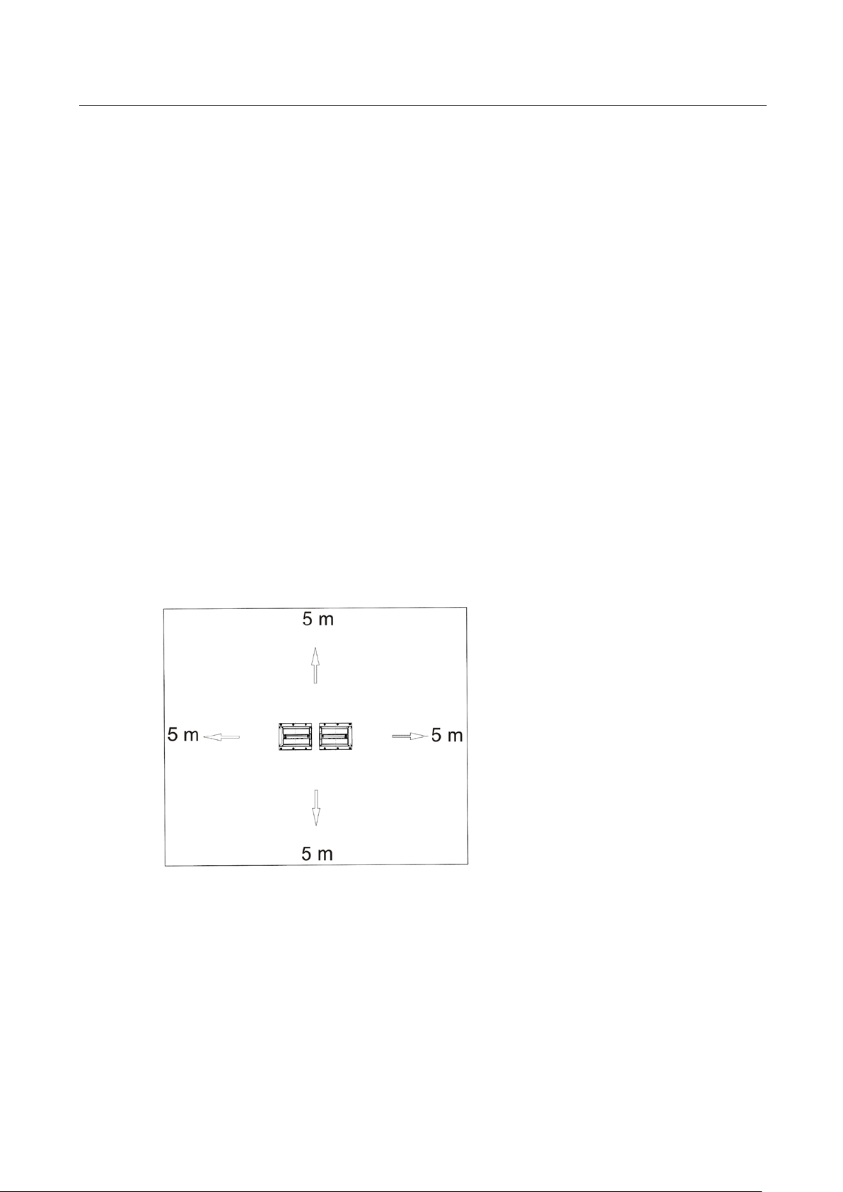
Menü-Aufruf nur außerhalb Rollensatz möglich!
Pos: 90 /Techn ische Dok ument atio n/Brem spr üftec hnik /- Arc hiv -/- Brems prüf technik A lle -/I nha lte/I nhalt : Me nüstr uktur (Abl auf) IWST @ 20\mod_1273504649880_75.docx @ 845818 @ @ 1
Pos: 91 /Techn ische Dok ument atio n/Brem spr üftec hnik /- Arc hiv -/- Brems prüf technik A lle -/I nha lte/I nhalt : Me nüstr uktur (Dia gramm ) I WST @ 20\mod_1273498931892_0.docx @ 845698 @ @ 1
1 OPEN
2 SELECT
3 CONFIRM
Pos: 92 /-----For ma t-----/MA N UEL LER UMB RUC H Se ite num br uch @ 0\m od_1134403577687_0.docx @ 1277 @ @ 1
Geräuschsuche
(nur Pkw!)
Haupt-Fahrtrichtung
Allrad-Gegenlauf
Gegen-Fahrtrichtung
BA022301-en
Page 28
28
► IWST 380 R120 or higher
Pos: 93 /Technische Dokument ation/Alle Gerät e/Übersc hriften/Üb erschriften oh ne Numme rier ung/Üb ersc hrift: > A b IWST 3 80 R120 @ 4 1\mod_1418730654899_75.docx @ 2175154 @ @ 1
Pos: 94 /Techn ische Dok ument atio n/Brem spr üftec hnik /MB T-SERI ES /0 2230 1 MBT LON / BA/I nhal t: 022 3 Me nüs truk tur ( Di agram m) ab I WS T 3 80 R 120 @ 4 1\mod_ 14187 33808 614_ 0.docx @ 2175 246 @ @ 1
Haupt-Fahrtrichtung
Geräuschsuche
(nur Pkw!)
Pos: 95 /-----For ma t-----/MA N UEL LER UMB RUC H Se ite num br uch @ 0\m od_1134403577687_0.docx @ 1277 @ @ 1
Allrad-Gegenlauf
Gegen-Fahrtrichtung
BA022301-en
Page 29

29
► IWST 380 R120 4WD or higher
Pos: 96 /Technische Dokume ntatio n/Alle Geräte/ Übersc hriften/ Überschr iften ohne N ummer ierun g/Übersc hrift: > Ab IWS T 3 80 R120 Allr ad @ 4 1\mod_1418730803894_75.docx @ 2175200 @ @ 1
Pos: 97 /Tec hn isch e Do kume ntatio n/Brem spr üftec hnik/M BT-SE RIE S/ 022 301 M BT L ON/ BA/ Inh alt: 0 223 Me nüs tr uktur ( Diagr amm ) a b IW ST 380 R12 0 Al lrad @ 4 0\mod_1415087307036_0.docx @ 2139244 @ @ 1
Allrad VISCO
Geräuschsuche
(nur Pkw!)
Pos: 98 /-----For ma t-----/MA N UEL LER UMB RUC H Se ite num br uch @ 0\m od_1134403577687_0.docx @ 1277 @ @ 1
Allrad-Starr
(Nur mit Lichtschranken möglich)
Allrad-Mode
Standard-Mode
BA022301-en
Page 30

30
5.5
Car Brake Tester with MAH-DOT and IFB
Brake Tester without Weighing Machine
1 5 8 0
Pos: 99 /Technische Dokument ation/Alle Gerät e/Übersc hriften/Üb erschriften 1. 1/P/Übersc hrift 1.1: PKW-Pr üfst and m it M AH-DO T u nd IFB @ 2 1\mod_ 127 78806 7466 1_75.d ocx @ 862 013 @ 2 @ 1
Pos: 100 /Te ch nisc he D ok umen tati on/ Bre mspr üftech nik/M BT-S ERIE S/ 0223 01 M BT LON/ BA/I nha lt : 02 23 M AH- DOT P lat ine (B ild) 2 @ 40\m od_ 14150 15205 466_0.d ocx @ 2 13909 1 @ @ 1
Pos: 101 /Tech nische Dok umen tati on/Br emsp rüfte chnik/ M BT-SE RIES /02 230 1 MB T LO N/ BA/I nha lt: 022 3 Be die nung PK W MAH -DO T und I FB (Text) 3 @ 41\mod_1418718037351_75.docx @ 2174958 @ @ 1
1 Drive onto roller set.
2 Press star key (M) for pointer stop.
3 Brake until slip or max. brake force.
4 Storage with keys F9 to F11.
• Front axle: F9 (I)
• Parking brake: F10 (J)
• Rear axle: F11 (K)
5 After testing, an auto OFF must be done. F12 (L) (not required with PC program
LON BASIC).
6 Use F7 (G) to start the print menu.
7 Enter the number of the print program, 1 or 2 and confirm with star (M) (not
required with PC program LON BASIC).
• An ovality measurement can be started with F4 (D).
• Re-display of the measurement values with F9 to F11.
• Re-display of the side-slip tester with Shift + Axle number + key F9 (I).
• Re-display of the shock absorber with Shift + Axle number + key F10 (J).
• Differential display of the brake force is numerical and via the LED bar.
Pos: 102 /Tech nische Dok umen tati on/Br emsp rüfte chnik/ M BT-SE RIES /02 230 1 MB T LO N/ BA/I nha lt: 022 3 Inf o PKW M AH-DOT und IFB @ 41\mod_1418720449557_75.docx @ 2175004 @ @ 1
New vehicle (NEW) with pound key (N) and star (M). (Delete all test values).
If there is a side-slip tester, shock absorber tester or both, it is necessary after the
Auto OFF procedure to set up a new vehicle (NEW). If not, then the measurement
values from the previous vehicle are still active.
Pos: 103 /Tech nische Dok umen tati on/Br emsp rüfte chnik/ M BT-SERIES/022301 MBT LON/BA/Inhalt: 0223 Prüfstand ohne Waage PKW2 @ 41\mod_1418722375130_75.docx @ 2175057 @ @ 1
With brake testers w/o weighing machine the vehicle weight must be entered after
the Auto OFF. The axle symbol changes constantly with the weight unit.
The weight entry is done directly via the numerical keypad of the remote control
and is confirmed with the star key (*). The left analog display runs synchronously
with the weight entry. Example: Entry of 1580 kilogram total weight.
Pos: 104 /-----F orm at-----/M ANUELLE R UMBR UCH Seite numbru ch @ 0\mod_1134403577687_0.docx @ 1277 @ @ 1
BA022301-en
Enter
on the keypad and confirm with the star (*) key.
Page 31

31
5.6
Car Brake Tester with MAH-DOT and RECO 1
Pos: 105 /Technische Dokum entati on/Alle G eräte/ Übers chrifte n/Über schrifte n 1.1/P/ Übers chrift 1.1: PK W-Prü fsta nd m it MA H-DO T und RE CO 1 @ 21\mod_1277881348839_75.docx @ 862103 @ 2 @ 1
Pos: 106 /Tech nische Dok umen tati on/Br emsp rüfte chnik/ M BT-SE RIES /02 230 1 MB T LO N/ BA/I nha lt: 022 3 Be die nung PK W MAH -DO T und REC O 1 ( Bi lder ) @ 21\mod_1277189731517_0.docx @ 858873 @ @ 1
A
C D
E
Pos: 107 /Tech nische Dok umen tati on/Br emsp rüfte chnik/ M BT-SE RIES /02 230 1 MB T LO N/ BA/I nha lt: 022 3 Be die nung PK W MAH -DO T und RE CO 1 (Tex t) @ 27\mod_1327397964107_75.docx @ 1514093 @ @ 1
1 Drive onto roller set.
B
F
2 Press blue Return key for pointer stop. Front axle symbol starts flashing (A).
3 Brake to slip or max. brake force.
4 Store with blue Return key.
5 Do axle change.
6 The symbol for Parking brake now flashes (B).
7 The parking brake measurement and rear axle measurement (C) are done using
the same procedure.
8 After storing the rear axle exit the roller set.
9 Now PRT (D) is flashing for printing. After confirming with the blue Return key,
the first LED of the differential display is flashing for print program. Use the
scroll key to select between program 1 or 2. Confirm again with Return and
print is done.
• Point 8 is omitted with PC program LON BASIC.
• An ovality measurement can be done with the right-hand Motor-ON key. The
ready lamp on the test stand is OFF during the measurement time.
BA022301-en
Page 32

32
Brake Tester without Weighing Machine
• Re-display of the measurement value: Use the scroll key to go to the axle and
press Return. Re-display of side-slip and shock absorber is not possible with
the RECO 1.
• If NEW (E) is confirmed with Return, then all existing measurement values are
deleted.
If there is no weighing machine, this can be entered at the end after Auto OFF
using the scroll key and Return. Visible by the last 4 LEDs (F) which are flashing,
and by the analog pointer.
If there is a side-slip tester, shock absorber tester or both, a new vehicle (NEW)
must be set up after Auto OFF. If not, these measurement values from the previous vehicle are still active.
Pos: 108 /-----F orm at-----/M ANUELLE R UMBR UCH Seite numbru ch @ 0\mod_1134403577687_0.docx @ 1277 @ @ 1
BA022301-en
Page 33

33
5.7
Truck Brake Tester with MAH-DOT and FFB
Pos: 109 /Technische Dokum entati on/Alle G eräte/ Übers chrifte n/Über schrifte n 1.1/ L/Übersc hrift 1 .1: L KW-Prüf stand m it MAH -DOT und FFB @ 21\m od_ 12778 81554 584_7 5.docx @ 86216 3 @ 2 @ 1
Pos: 110 /Tech nische Dok umen tati on/Br emsp rüfte chnik/ M BT-SE RIES /02 230 1 MB T LO N/ BA/I nha lt: 022 3 Be die nung L KW M AH-D OT und FFB (Text ) @ 27\mod_1327398079546_75.docx @ 1514137 @ @ 1
1 Drive onto roller set.
2 Active pressure sensor starts flashing. If several Px sensors are registered,
another sensor can be selected using the desired sensor number and pound
key (#). After the measurement the sensors cannot be allocated!
3 Press F8 (H) key for pointer stop.
4 Brake until slip or max. brake force.
5 Enter axle number 1 to 9, F9 for Service brake or F10 for Parking brake and
confirm with star key (*).
6 Do axle change and test all axles. Once all axles are tested, do an Auto Off
using Remote control F12 (L).
• Press F12. END flashes at the display. Confirm with the star key.
• END stops flashing. Calculations are started.
• After the calculations are complete, [E] appears. Now printing can be done.
7 The print program is started with F7 (G). Enter program number 1, 2, 3, 4 or 9
and confirm with the star key (*). Printout follows.
• An ovality measurement can be started with F4 (D).
• Re-display of the Service brake with axle number + key F9 (I).
• Re-display of the Parking brake with axle number + key F10 (J).
• Re-display of the Final evaluation with 0 + key F9 or F10.
Pos: 111 /-----F orm at-----/M ANUELLE R UMBR UCH Seite numbru ch @ 0\mod_1134403577687_0.docx @ 1277 @ @ 1
• Re-display of the Side-slip tester with Shift + axle number +key F9 (I).
BA022301-en
Page 34

34
Brake Tester without Scale
Pos: 112 /Te ch nisc he D okum enta tion/ Bremsp rüfte chnik/M BT- SERIE S/ 0223 01 M BT LON /BA/ In halt : 02 23 P rüfs ta nd o hne Waa ge LKW FF B 3 ( Text) @ 27\mod_1327398201270_75.docx @ 1514181 @ @ 1
With brake testers without scale the vehicle weight must be entered after the Auto
OFF. The axle symbol (A) changes constantly with the weight unit (B). Display 1, if
present, flashes for input.
The weight entry is done directly via the numerical keypad of the remote control
and is confirmed with the star key (*). The input is displayed on Display 1 (C). The
analog display runs synchronously with the weight input.
Example: Entry of 15.80 tons.
Pos: 113 /Te ch nisc he D ok umen tati on/Br emsp rüfte chnik/M BT- SERIE S/ 0223 01 M BT LON /BA/ In halt : 02 23 P rüfs ta nd o hne Waa ge LKW FF B 3 ( Bild er) @ 2 1\mod_1277202240788_0.docx @ 860153 @ @ 1
Enter 1 5 8 0 via the keyboard and confirm with star (*) key.
A
C
Pos: 114 /-----F orm at-----/M ANUELLE R UMBR UCH Seite numbru ch @ 0\mod_1134403577687_0.docx @ 1277 @ @ 1
B
BA022301-en
Page 35

35
5.8
Truck Brake Tester with MAH-DOT and RECO 1
Brake Tester without Scale
Pos: 115 /Technische Dokum entati on/Alle G eräte/ Übers chrifte n/Über schrifte n 1.1/ L/Übersc hrift 1 .1: L KW-Prüf stand m it MAH -DOT und RECO 1 @ 21\mod_127 78814 37722_ 75.d ocx @ 86 2133 @ 2 @ 1
Pos: 116 /Te ch nisc he D ok umen tati on/Br emsp rüftec hnik/M BT-S ERIE S/ 0223 01 M BT LON /BA/ Inh alt : 02 23 B edie nu ng L KW MAH -DOT un d RECO 1 (Text) @ 27\mod_1327398290937_75.docx @ 1514225 @ @ 1
1 Drive onto roller set.
2 Active pressure sensor (A) starts flashing. If several Px sensors are registered,
another sensor can be selected using the scroll key. After the measurement,
allocation of the sensors is not possible!
3 Press the blue Return key for pointer stop.
4 Brake to slip or max. brake force.
5 Press blue Return key for filing mode. Use the scroll key to select Service brake
(B) or Parking brake (C).
6 Use the scroll key to select axle 1 to 9 and confirm with Return. Measurements
are stored (D + E).
7 Do axle change and test all axles using the above procedure. Once all axles are
tested, do an Auto OFF (F) using remote control (O).
8 For printing, select the print mode using the scroll key and confirm with Return.
Now PRT (G) is flashing for print. After confirmation with the blue Return key the
first LED of the differential display flashes for print program 1. Use the scroll key
to select program 1, 2, 3, 4 or 9. Confirm print program with Return, printout is
Pos: 117 /Tech nische Dok umen tati on/Br emsp rüfte chnik/ M BT-SE RIES /02 230 1 MB T LO N/ BA/I nha lt: 022 3 Pr üfs tand ohn e Waage LKW RECO 1 (Text) @ 41\mod_1418723207295_75.docx @ 2175103 @ @ 1
done.
With brake testers without scale the vehicle weight must be entered after the Auto
OFF. The axle symbol (A) changes constantly with the weight unit (B), and the last
4 LEDs are flashing.
The entry is done with the scroll-up key of the Reco1. As soon as the weight input
is confirmed with Return, the corresponding LED changes to permanent light. The
analog display runs synchronously with the weight input.
Example: Entry of 15.80 tons.
The last 4 LEDs are flashing.
1 Press the scroll-up key once and confirm with Return. (The first LED goes to
permanent light.)
2 Press the scroll-up key five times and confirm with Return.
3 Press the scroll-up key eight times and confirm with Return.
4 Confirm the last LED with Return for 0.
Pos: 118 /Tech nische Dok umen tati on/Br emsp rüfte chnik/ M BT-SE RIES /02 230 1 MB T LO N/ BA/I nha lt: 022 3 Pr üfs tand ohn e Waa ge LK W RECO 1 ( Bild er) @ 21\mod_1277196719094_0.docx @ 859383 @ @ 1
5 The MAH-DOT changes to the Print symbol.
BA022301-en
Page 36

36
5.9
Option Drive Control
A
Pos: 119 /Technische Dokum entati on/Alle G eräte/ Übers chrifte n/Über schrifte n 1.1/O/ Übers chrift 1.1: Op tion Drive C ontrol @ 21\mod_1277881917245_75.docx @ 862223 @ 2 @ 1
Pos: 120 /Tec hnis che D okum enta tion/ Brem spr üftech nik/M BT-S ERIE S/ 0223 01 M BT LON /BA/ Inh alt : 02 23 B edie nu ng Dr iv e C ontr ol (B ilde r) @ 2 1\mod _12 77290 5195 24_0.d ocx @ 860 353 @ @ 1
A
Pos: 121 /Te ch nisc he D okum enta tion/ Bremsp rüfte chnik/M BT- SERIES/022301 MBT LON/BA/Inhalt: 0223 Bedienung der Option Drive Control (Text) @ 27\mod_1327401257433_75.docx @ 1514373 @ @ 1
1 Drive onto the roller set with a 4WD vehicle.
2 After 2-time start-up monitoring the test stand switches automatically to DCO.
The DCO lamp starts flashing. The left roller starts automatically in driving
direction, the right-hand one in the opposite direction.
3 Brake with connected pedal force meter to max. brake force or slip. Release
brake. The display shows the driving direction of the wheels (Fig. A).
B
B
4 Now the right-hand wheel starts automatically in driving direction, the left-hand
wheel in opposite direction. Brake to the same pedal force of the left-hand
wheel. Once pedal force is reached, release brake. The rollers stop without re-
starting. The display shows the wheels’ driving direction. Pointers go to the
maximum value respectively. Now store at the respective axle using the remote
control. Change to the next axle.
5 Test the other axle as described above.
Store using keys F9 –F11.
• Front axle: F9 (I)
• Parking brake: F10 (J)
• Rear axle: F11 (K)
After the measurements an “Auto OFF“ must be done.
F12 (L)! (not necessary if evaluation is done via PC-LON BASIC Program)
BA022301-en
Page 37

37
Special Features
• When exiting the roller set, the test stand returns automatically to Standard
mode.
• Repeat measurement: After measurement of the left-hand and right-hand
wheels the rollers are at a standstill. Now storage is possible, or the measure-
ment can be repeated with the green key, or the Parking brake can be tested.
• Outside of the roller set the DCO can be activated with “Auto Off“ key (L) and
the arrow-up key (Y). Confirm with the star key (M). DCO lamp starts flashing.
This saves from doing the start-up monitoring twice in the roller set.
• After 3 start-up monitorings the rollers stop and the tester changes from Drive
Control Mode to manual standard mode. Motors can be started individually via
Pos: 122 /-----F orm at-----/M ANUELLE R UMBR UCH Seite numbru ch @ 0\mod_1134403577687_0.docx @ 1277 @ @ 1
the remote control. The display shows DC as optical help (Fig. B).
BA022301-en
Page 38
38
5.10
Noise Detection with IFB / FFB / RECO 1
Activation via IFB / FFB
unoccupied
Activation via RECO 1
Pos: 123 /Technische Dokum entati on/Alle G eräte/ Übers chrifte n/Über schrifte n 1.1/G/ Übers chrift 1.1: Ger äuschs uche m it IF B / FFB / REC O 1 @ 21\mod _127 78820 21473 _75.d ocx @ 86 2253 @ 2 @ 1
Pos: 124 /Tech nische Dok umen tati on/Br emsp rüfte chnik/ M BT-SERI ES/ 0223 01 MB T LON /BA/I nha lt: 0223 B edie nung Gerä uschs uche mit IFB / FFB (Tex t) @ 27\m od_ 132 74023 411 18_75.docx @ 1514417 @ @ 1
Activation is only possible with unoccupied tester.
1 Press Auto-Off key (Display shows END).
2 Select Noise Detection symbol (C) with the arrow key and confirm with the star
key.
3 Drive onto the shock absorber tester.
4 Start the respective side with motor On left / right.
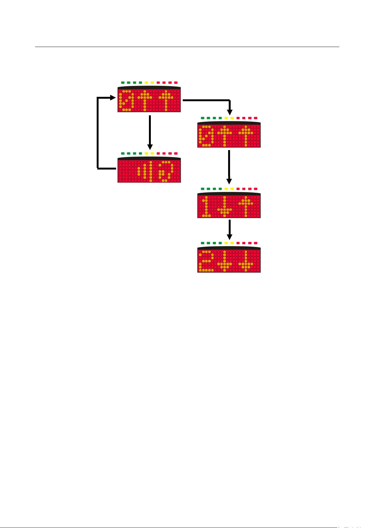
5 The motor RPM can be regulated using the potentiometer (A). Only when
rotary switch on the tester is set to Noise Detection.
6 Press one of the red keys for motor stop.
7 Noise detection can be quit using the pound key (#) with
stand.
• The switch on the tester (B) must be set to Noise Detection for RPM regulation
Pos: 125 /Te ch nisc he D ok umen tati on/Br emsp rüfte chnik /M BT-SERI ES/ 0223 01 MB T LON /BA/I nha lt: 0223 B edie nung Gerä uschs uche mit IFB / FFB / REC O 1 (Bild er) @ 2 1\mod _1277 3622 25072_ 0.doc x @ 86048 3 @ @ 1
Pos: 126 /Tech nische Dok umen tati on/Br emsp rüfte chnik/ M BT-SE RIES /02 230 1 MB T LO N/ BA/I nha lt: 022 3 Be die nung Ger äu schs uc he m it RE CO 1 ( Text ) @ 27\mod_1327402435941_75.docx @ 1515061 @ @ 1
of the motors. Otherwise no RPM regulation is possible.
A B C
test
BA022301-en
1 Press the Motor Off key.
2 Select Noise Detection symbol (C) using the arrow key. Confirm with Return.
3 Drive onto shock absorber tester.
4 Start the respective side with Motor ON left / right.
5 The motor RPM can be regulated using the potentiometer (A). Only when
rotary switch on the test stand is set to Noise Detection.
6 Press the motor OFF key for motor stop.
Page 39

39
unoccupied
7 Noise detection can be quit using Motor OFF key with
• The switch (B) on the test stand must be set to Noise Detetcion for the RPM
Pos: 127 /-----F orm at-----/M ANUELLE R UMBR UCH Seite numbru ch @ 0\mod_1134403577687_0.docx @ 1277 @ @ 1
regulation of the motors. Otherwise no RPM regulation is possible.
test stand.
BA022301-en
Page 40

40
5.11
MSD 3000
Test
Pos: 128 /Technische Dokum entati on/Alle G eräte/ Übers chrifte n/Über schriften 1.1/M/Überschrift 1.1: MSD 3000 @ 24\mod_13064 88669 901_0. docx @ 1 01318 3 @ 2 @ 1
Pos: 129 /Tech nische Dok umen tati on/Br emsp rüfte chnik/ M BT-SERIES/022301 MBT LON/BA/Inhalt: 0223 Bedienung MSD 3000 (Bilder) @ 21\mod_12773671 61654_ 0.doc x @ 860633 @ @ 1
A
B C
D E
Pos: 130 /Tech nische Dok umen tati on/Br emsp rüfte chnik/ M BT-SE RIES /02 230 1 MB T LON/BA/Inhalt: 0223 Bedienung MSD 3000 (Text) @ 27\mod_1327402629870_75.docx @ 1515105 @ @ 1
1 Drive onto the MSD (A). Weight measurement (B)!
2 Both sides start up simultaneously (C).
3 After measurement completion the pointers move to test value 0 to 0.3 D. If the
test value is above 0.3, the pointers move slightly above 0.3 D.
• The display changes between the unit (D) and the difference (E) in % until the
tester is exited. The differential value is based on the left and right measurement
value.
• If the measurement value of a wheel is under 0.13 D, or if the difference is
> 29%, then an additional single wheel measurement is done of each wheel.
The display flashes during the single wheel measurement (C).
BA022301-en
4 Measurement values are automatically stored without remote control.
With 2 additional AN5-Displays the wheel weight is displayed during the measurement procedure, and the measurement value 0…0.3 is displayed after completed measurement.
Page 41

41
Printing and Re-display of the Measurement Values
not
(Re-display of the measurement values is
control.)
• The print program is started with F7. Enter Program 1 and confirm with star key
(*). Printout follows.
• Re-display of the shock absorber with Shift + Axle number + key F10.
If AN5 displays are present, press the F10 key again to switch to the wheel
weight.
• Re-display of the side-slip tester with Shift + Axle number + key F9 if available.
• New vehicle (NEW) with pound key # and star key * (Delete all measurement
Pos: 131 /-----Format-----/MA NUELLE R UMBR UCH Seitenum bruch @ 0\mod_1134403577687_0.docx @ 1277 @ @ 1
values).
possible with the RECO remote
BA022301-en
Page 42

42
5.12
Clock Changing between Daylight Saving Time/Standard Time
One Hour Forward
one hour forward
One Hour Back
one hour back
Pos: 132 /Technische Dokum entati on/Alle G eräte/ Übers chrifte n/Über schrifte n 1.1/ U/Übersc hrift 1.1: Um stellu ng S ommerzei t/Norm alze it @ 21\mod_ 12778 8175 6766_ 75.d ocx @ 862 193 @ 2 @ 1
Pos: 133 /Tech nische Dok umen tati on/Br emsp rüfte chnik/ M BT-SE RIES/ 02230 1 MBT LON/BA/I nhalt: 02 23 Ums tellun g Somme r-/W interz eit @ 2 7\mod_ 1327 402 73058 0_75.docx @ 1515149 @ @ 1
1 Turn on the main switch of the tester by holding the power-on key down and
waiting until the left-hand pointer (small measurement range 0-8 kN) moves to
3.2 (kN) Now release the power-on key.
2 Press the Start key twice so that the pointer moves to 4.2 (kN) (small
measurement range left).
3 Now press the Return key (↵ or *) on the remote control.
4 The clock has now been put
header is printed out with the new time.
5 Switch the main switch off and on again. Now the tester is ready for operation
with the new time.
1 Turn on the main switch of the tester by holding the power-on key down and
waiting until the left-hand pointer (small measurement range 0-8 kN) moves to
3.2 (kN). Now release the power-on key.
2 Press the start key three times so that the pointer moves to 4.4 (kN) (small
measurement range left).
3 Now press the Return key (↵ or *) on the remote control.
4 The clock has now been put
header is printed out with the new time.
5 Switch the main switch off and on again. Now the tester is ready for operation
with the new time.
The changeover only takes place on the control PCB and is not shown on the
simultaneous display.
Pos: 134 /-----F orm at-----/M ANUELLE R UMBR UCH Seite numbru ch @ 0\mod_1134403577687_0.docx @ 1277 @ @ 1
. As confirmation the customer
. As confirmation the customer
BA022301-en
Page 43

43
5.13
Test Procedure with Software
Button
Key
Assignment
Pos: 135 /Technische Dokum entati on/Alle G eräte/ Übers chrifte n/Über schrifte n 1.1/P/ Übers chrift 1.1: Pr üfabla uf mit Softw are @ 9\m od_1207903111456_75.docx @ 184601 @ 2 @ 1
Pos: 136 /Tech nische Dok umen tati on/Br emsp rüfte chnik/ M BT-SE RIES /02 230 1 MB T LO N/ BA/I nha lt: 022 3 Pr üfa bla uf m it LO N BASIC @ 27\mod_1327402841773_75.docx @ 1515193 @ @ 1
F2 Previous page
F3 Next page
F4 Start page (main menu)
Page ↑
One level up
Page ↓ One level down
F1 Start help
F12 Start printout
Esc Exit page
► When the green LED in the main
menu lights up, the system is ready
for testing.
BA022301-en
Page 44

44
1 Conduct a brake test for front axle, parking brake and rear axle.
Selection between digital and analog
display:
• Main menu
• <F7> System
• <2> Settings
• <K> Softdips miscellaneous
• <22> IWST
► After test completion this screen ap-
pears.
BA022301-en
Page 45

45
2a Use <1> to load an existing data rec-
ord.
3a Use <5> to store the measurement
intermediately, e. g. if you want to re-
peat the test later.
2b Use <6> to create a new data record.
3b Use <4> to finish and save the
measurement.
4 Use <F12> to print out the test re-
sults.
5 To exit the program, press <Esc> in
the main menu and confirm with
<F2>.
Pos: 137 /-----F orm at-----/M ANUELLE R UMBR UCH Seite numbru ch @ 0\mod_1134403577687_0.docx @ 1277 @ @ 1
BA022301-en
Page 46
46
6
Maintenance
6.1
Annual Inspection
12 (twelve) months
6.2
Care Instructions
6.3
Spare Parts
Pos: 138 /Te ch nisc he D ok umen tation/A lle G eräte/ Überschr iften/Üb erschr iften 1/I /Über schrif t 1: Ins tandh altung @ 28\mod_1332159812536_75.docx @ 1565908 @ 1 @ 1
Pos: 139 /Technische Dokum entati on/Alle G eräte/I nha lte/Warn ung!/Inh alt: War nun g - Haup tschal ter aus b ei Ins tand halt ung_ 12p t @ 26\mod_1324465229892_75.docx @ 1140563 @ @ 1
Danger! Electric shock hazard!
Before doing any maintenance work, turn off the main switch and protect it
against tampering.
Pos: 140 /Te ch nisc he D ok umen tati on/A ll e Ger äte/Überschr iften/Üb erschrifte n 1.1/J/Überschr ift 1.1: Jährli che Überprüfun g @ 28\mod_1332230089694_75.docx @ 1566204 @ 2 @ 1
Pos: 141 /Tech nische Dok umen tati on/A lle G eräte/ Inha lte/ Info!/I nha lt: Inf o - Jähr liche Überpr üfung_ 12p t @ 25\mod _132 446 048 107 5_ 75.d ocx @ 1 139 412 @ @ 1
• The maintenance interval prescribed by the manufacturer is
This maintenance interval refers to normal workshop usage. If the equipment is
used more frequently or under severe operating conditions (e.g. outdoors), the
interval must be reduced accordingly.
• Maintenance work shall be done only by authorized and trained service techni-
cians provided by the manufacturer, licensed dealers or service partners.
• In case of non-compliance the manufacturer's warranty becomes void.
Pos: 142 /Technische Dokum entati on/Alle G eräte/ Übers chrifte n/Über schrifte n 1.1/P/ Übers chrift 1.1: Pf legehi nweise @ 15\mod_1245912234854_75.docx @ 395780 @ 2 @ 1
.
Pos: 143 /Tech nische Dok umen tati on/A lle G eräte/ Inha lte/ Inhalt : Pf lege hinwe ise - Alle Geräte_ 12pt @ 26\mod_1324468886116_75.docx @ 1141252 @ @ 1
• Periodically clean the equipment and treat it with a care product.
• Repair damage to the paintwork immediately to prevent corrosion.
• Usage of caustic cleaning agents or high pressure and steam jet cleaners may
Pos: 144 /Tech nische Dok umen tati on/A lle G eräte/ Inha lte/ Info!/I nha lt: Inf o - Pfle gehi nweise_ 12p t @ 26\mod_1324461215655_75.docx @ 1139602 @ @ 1
lead to equipment damage.
Regular care and maintenance is the key condition for functionality and long life
expectancy of the equipment!
Pos: 145 /Technische Dokum entati on/Alle G eräte/ Übers chrifte n/Über schrifte n 1.1/E/ Über schrift 1.1: Er satz teile @ 18\ mod_1255596847002_75.docx @ 474414 @ 2 @ 1
Pos: 146 /Technische Dokum entati on/Alle G eräte/I nha lte/Inha lt: Ersatz teile - Alle Ger äte_12pt @ 26\mod_1324468768120_75.docx @ 1141219 @ @ 1
To ensure safe and reliable operation, only use original spare parts supplied by the
Pos: 147 /-----F orm at-----/M ANUELLE R UMBR UCH Seite numbru ch @ 0\mod_1134403577687_0.docx @ 1277 @ @ 1
equipment manufacturer.
BA022301-en
Page 47

47
6.4
Chain Drive Maintenance: Cleaning, Retensioning, Lubricating
Cleaning the Chains
Retensioning the Chains
Brake tester
model
Thread
Strength
Tightening
torque
Position
Required for chain
tensioning?
Pos: 148 /Technische Dokum entati on/Alle G eräte/ Übers chrifte n/Über schrifte n 1.1/I/ Über schrift 1.1: I nstandh altung d es Ket tentrieb s: R einigen, N achsp annen, Schmi eren @ 36\mod_1394630342377_75.docx @ 1918730 @ 2 @ 1
Pos: 149 /Te ch nisc he D ok umen tati on/A ll e Ger äte/I nha lte/I nfo!/I nha lt: Inf o - W artu ngsin terva ll: Mona tlich _12p t @ 26\mod_1324463913433_75.docx @ 1140268 @ @ 1
Pos: 150 /Tech nische Dok umen tati on/Br emsp rüfte chnik/ - Ar ch iv -/- Br ems pr üfte chn ik A lle -/Inh alte/I nhal t: 0 200 Kette n ins tand ha lten E in leitu ng_1 2pt @ 3 3\mod_1374065936693_75.docx @ 1809475 @ @ 1
Before doing any maintenance work, turn off the main switch and protect it
against tampering.
Remove the roller set covers from above the chains, reinstall before restarting the
Pos: 151 /Tech nische Dok umen tati on/Br emsp rüfte chnik/ - Ar ch iv -/- Br ems pr üfte chn ik A lle -/Inh alte/I nhalt: 0200 Kette n rein igen_1 2pt @ 33\mod_1374064814451_75.docx @ 1809387 @ @ 1
brake tester.
The chains can normally be cleaned using a cloth or brush, stubborn dirt can be
removed with petroleum solvent or benzine. Do not use pickles or acids! Reapply
a new anticorrosive film immediately after using degreasing agents (see section
Pos: 152 /Tech nische Dok umen tati on/Br emsp rüfte chnik/ - Ar ch iv -/- Br ems pr üfte chn ik A lle -/Inh alte/ Inhal t: 0 200 Kette n nac hspan ne n_12pt @ 3 3\mod_1374065445290_75.docx @ 1809431 @ @ 1
"Greasing the Chains").
Check the chain slack: the chain should be movable by hand approx. 5 mm up
and down. If the chain needs retensioning, proceed as follows:
• Open the fastening screws.
• Adjust the chain tension using the tensioning screw.
Maintenance interval: Monthly
• Tighten the fastening screws (see table for torque figures).
Pos: 153 /Tech nische Dok umen tati on/Br emsp rüfte chnik/ - Ar chiv -/- Br ems pr üfte chnik A lle -/Inh alte/In halt: 0200 Ke tten nac hspanne n - Anzu gsmom ente @ 3 4\mod_1378969980518_75.docx @ 1825309 @ @ 1
• Recheck the chain slack.
MBT
1xxx/2xxx/3xxx
MBT 4xxx
MBT 5xxx
MBT 6xxx/7xxx
MBT 7xxx
M10 8.8 50 Nm Running roller yes
M16 8.8 120 Nm Motor mount yes
M18 8.8 350 Nm Running roller yes
M20 8.8 350 Nm Motor mount only for RS1
M16 8.8 220 Nm Running roller no
M18 8.8 350 Nm Motor mount yes
M18 8.8 350 Nm Running roller yes
M20 8.8 350 Nm Motor mount only for RS1 + RS3
M18 8.8 500 Nm
Raised running
roller
yes
M27 8.8 500 Nm Motor mount 3:4 no
Pos: 154 /-----F orm at-----/ MANUE LLE R UMBR UCH Seite numbru ch @ 0\mod_1134403577687_0.docx @ 1277 @ @ 1
BA022301-en
Page 48

48
Lubricating the Chains
Important: The lubricant must contact the chain links!
Pos: 155 /Tech nische Dok umen tati on/Br emsp rüfte chnik/ - Ar ch iv -/- Br ems pr üfte chn ik A lle -/Inhal te/Inhalt: 0200 Ketten schmier en_12pt @ 33\mod_1374063619890_75.docx @ 1809299 @ @ 1
The service lifetime of the chains directly depends on correct lubrication. Provided
that the lubricating film is continuously maintained, chain wear can be reduced to
a minimum
Recommended lubricant: LongLub adhesive lubricant (MAHA part # 35 1020)
• Lubricate the chain over its entire length while turning over the rollers by hand.
Pos: 156 /Tech nische Dok umen tati on/Br emsp rüfte chnik/ - Ar ch iv -/- Br ems pr üfte chn ik A lle -/Inhal te/In halt: 0 200 Ke tten schm ieren (Bild) @ 33\ mod_1374060263983_0.docx @ 1809079 @ @ 1
Pos: 157 /-----F orm at-----/M ANUELLE R UMBR UCH Seite numbru ch @ 0\mod_1134403577687_0.docx @ 1277 @ @ 1
BA022301-en
Page 49
49
► M BT 3x00
A
B
C
Pos: 158 /Technische Dokum entati on/Alle G eräte/ Übers chrifte n/Über schrifte n ohne N umm erierung/ Übers chrift: > MBT 3x00 @ 23\mod_1297073990557_0.docx @ 971184 @ @ 1
Pos: 159 /Tech nische Dok umen tati on/Br emsp rüfte chnik/ - Ar ch iv -/- Br ems pr üfte chn ik A lle -/Inh alte/ Inhal t: I nst Ke ttens pa nnun g (Bi lder) M BT 3x00 @ 1 8\mod_ 12 54727 296 554_ 0.d ocx @ 456 256 @ @ 1
Pos: 160 /Tech nische Dok umen tati on/Br emsp rüfte chnik/ - Ar ch iv -/- Br ems pr üfte chn ik A lle -/Inh alte/ Inhal t: 0 200 Kette n nac hspan ne n (Leg ende) @ 3 8\mod_1402493705606_75.docx @ 2023775 @ @ 1
Chain
Pos: 161 /-----F orm at-----/M ANUELLE R UMBR UCH Seite numbru ch @ 0\mod_1134403577687_0.docx @ 1277 @ @ 1
Fastening screws
Tensioning screw
BA022301-en
Page 50

50
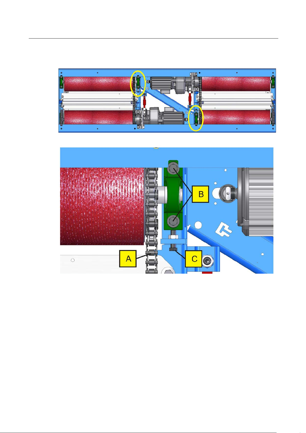
► M BT 4x00/7x00
A
B
C
B
Pos: 162 /Technische Dokum entati on/Alle G eräte/ Übers chrifte n/Über schrifte n ohne N umm erieru ng/Übers chrift: > M BT 4x 00/7x0 0 @ 38\mod _14 04283 3952 54_0.d ocx @ 204 9124 @ @ 1
Pos: 163 /Tech nische Dok umen tati on/Br emsp rüfte chnik/ - Ar ch iv -/- Br ems pr üfte chn ik A lle -/Inh al te/I nhal t: Inst Ke ttens pa nnun g ( Bild er) MB T 4x 00/ 7x0 0 @ 18\mod_1254730465742_0.docx @ 456523 @ @ 1
C
B
Pos: 164 /Tech nis che D okume nta tion/ Brems prüf tech nik/- Arch iv -/- B rem spr üfte ch nik A lle -/Inh alte/ In halt: 0200 Kette n nac hsp anne n (Leg ende) @ 38\mod_1402493705606_75.docx @ 2023775 @ @ 1
Chain
Pos: 165 /-----F ormat -----/M ANUELLE R UMBR UCH Seitenum bruch @ 0\ mod_1134403577687_0.docx @ 1277 @ @ 1
A
Fastening screws
Tensioning screw
BA022301-en
Page 51

51
6.5
Greasing the Sensor Roller Hinges
► M BT 3x00
Pos: 166 /Technische Dokum entati on/Alle G eräte/ Übers chrifte n/Über schrifte n 1.1/ T/Übersc hrift 1.1: Tas trolle nschar niere sc hmier en @ 36\mod_1394630469531_75.docx @ 1918774 @ 2 @ 1
Pos: 167 /Tech nische Dok umen tati on/A lle G eräte/ Inha lte/ Info!/I nha lt: Inf o - Wart ungs in terv all: 20 0 h / 12 M on ate _12p t @ 26\mod_1324463609793_75.docx @ 1140170 @ @ 1
Pos: 168 /Tech nische Dok umen tati on/Br emsp rüfte chnik/ - Ar ch iv -/- Br ems pr üfte chn ik A lle -/Inh al te/I nhal t: Inst Tas tro llen (T ext) M BT 3x 00/ 4x00/ 7x 00_ 12p t @ 26\mod_1326874914374_75.docx @ 1511547 @ @ 1
Grease the sensor roller hinges every 200 (two hundred) operating hours or once
annually.
1 Remove the cover plates from the roller set.
2 Treat the greasing points (D) using a spray lubricant. Move the sensor roller up
and down.
Pos: 169 /Tech nische Dokum entati on/Alle G eräte/ Übers chrifte n/Über schrifte n ohn e Numm erieru ng/Über schrift: > M BT 3x00 @ 23\mod_1297073990557_0.docx @ 971184 @ @ 1
Pos: 170 /Tech nische Dok umen tati on/Br emsp rüfte chnik/ - Ar ch iv -/- Br ems pr üfte chn ik A lle -/Inhalte/I nhalt: Inst T astroll en (B ilder) M BT 3x0 0 @ 18\m od_1254732674783_0.docx @ 456550 @ @ 1
3 Reinstall the cover plates to the roller set.
Maintenance interval: 200 hours / 12 months
Pos: 171 /-----F orm at-----/M ANUELLE R UMBR UCH Seite numbru ch @ 0\mod_1134403577687_0.docx @ 1277 @ @ 1
BA022301-en
Page 52

52
► M BT 4x00/7x00
6.6
Troubleshooting
Pos: 172 /Te ch nisc he D ok umen tati on/A ll e Ger äte/Über schr iften/Üb erschrif ten ohn e Numm erieru ng/Üb erschri ft: > M BT 4x 00/7x00 @ 3 8\mod_ 1404 2833 95254_ 0.docx @ 2049 124 @ @ 1
Pos: 173 /Tech nische Dok umen tati on/Br emsp rüfte chnik/ - Ar ch iv -/- Br ems pr üfte chn ik A lle -/Inh alte/ Inhal t: I nst Tastrollen (Bilder) MBT 4x00/7x00 @ 18\mod_1254734588264_0.docx @ 456847 @ @ 1
Pos: 174 /Technische Dokum entati on/Alle G eräte/ Übers chrifte n/Über schrifte n 1.1/ F/Übersc hrift 1 .1: F ehlerbeh ebung @ 8\mod_1206714646748_75.docx @ 17962 0 @ 2 @ 1
Pos: 175 /Tech nische Dok umen tati on/Br emsp rüfte chnik/ M BT-SE RIES /02 230 1 MB T LO N/ BA/I nha lt: 022 3 F ehler beh eb ung E in leit ung @ 38\ mod_1404212124733_75.docx @ 2049022 @ @ 1
• The brake tester shows an error code when there is a malfunction. The error
code is indicated by the pointers of the small measurement range. All error
codes (except for 33) can be acknowledged with the Error acknowledgement
key.
• The roller set starts up automatically when a vehicle is on the roller set with the
setting 'Automatic start-up Yes'!
• A few seconds must pass between switching the tester off and on, so that the
Pos: 176 /-----F orm at-----/M ANUELLE R UMBR UCH Seite numbru ch @ 0\mod_1134403577687_0.docx @ 1277 @ @ 1
BA022301-en
tester can be properly re-started.
D
Page 53

53
Pos: 177 /Tech nische Dok umen tati on/Br emsp rüfte chnik/ M BT-SE RIES/ 02230 1 MBT LON/BA/I nhalt: 02 23 Feh lerbeh ebun g Tabell e @ 38\mod_1404212074260_75.docx @ 2048976 @ @ 1
Error code Cause Remedy
01 Side-slip tester node Contact service.
02 SA 2 D node Contact service.
03 LON MOREG Contact service.
11 LON BPLKW node
12
Multi-function display (e.g. MFA
DOT) missing.
Left- and/or right-side overload
protection switch(es) Off.
22
Motor damage may have occurred.
Left-side speed sensor defective.
32 1)
Slip monitoring on left side disabled as safety feature! Contact service! Tyre damage!
Neither left- nor right-side speed
pulses.
Check node and LON network.
Contact service.
Contact service.
Position overload protection
switch(es) to 1, main switch OFF
and ON.
Check sensor for switching
clearance and proper contact of
connections. Contact service.
Check sensors for switching
clearance and proper contact of
connections. Contact service.
33
34 1)
40
Selector switch for '2 measuring
directions' (optional) on position 0.
Fuse of phase L2 and/or L3 triggered.
In case of persisting errors shut down the tester and contact
service!
Right-side speed sensor defective.
Slip monitoring on right side disabled as safety feature! Contact service! Tyre damage!
Faulty zero point adjustment of
pointers.
Drive vehicle off rollers and turn
selector switch to position '1' or
'2'.
Switch off tester and replace
fuses.
Check sensor for switching
clearance and proper contact of
connections. Contact service.
Drive vehicle off rollers, turn off
main switch and on again.
BA022301-en
Page 54

54
Error code Cause Remedy
In case of persisting errors shut down the tester and contact
service!
Error occurs after the tester was
41
Only left-side sensor roller
pressed.
switched on. It is likely that a
sensor roller switch is defective.
Error occurs after a vehicle drives
onto the roller set: Vehicle is per-
haps not positioned properly on
Only right-side sensor roller
pressed.
42
the roller set (only one sensor
roller pressed). Re-position vehi-
cle axle and then press the
"Power On" key.
Use extreme caution! Contact service immediately if there is
sensor roller malfunction.
43 2) MOREG error (general). Contact service.
44 2)
45 2)
No signals from left-side light barrier.
No signals from right-side light
barrier.
46 2) No signals from both light barriers.
50 Zero point of scale out of range. Contact service.
51
Tester already occupied with vehicle when switched on.
61 LON network error.
62
1
) Error messages can be confirmed with the Error acknowledgement key.
Emergency shutdown due to excessive brake force.
Afterwards the pointers on the analog display move to the zero point and the
tester is ready for operation. Please note, however, that weight and brake force
measurement as well as slip monitoring will not function properly.
2
Pos: 178 /-----F orm at-----/M ANUELLE R UMBR UCH Seite numbru ch @ 0\mod_1134403577687_0.docx @ 1277 @ @ 1
) Applicable for 4WD testers only.
Position reflector strips correctly.
Light barrier may be defective.
In addition, red Error lamp is
flashing:
Slowly left side
Fast right side
Fast/Slowly both
If driven axle of vehicle is on the
roller set, start rollers using re-
mote control and exit test stand.
BA022301-en
Page 55

55
7
Dismantling
8
Disposal
Pos: 179 /Technische Dokum entati on/Alle G eräte/ Übers chrifte n/Über schrifte n 1/D/Üb ers chrift 1: Demon tage @ 19\m od_12 66336 8228 63_75. docx @ 74 2452 @ 1 @ 1
Pos: 180 /Technische Dokum entati on/Alle G eräte/I nha lte/Inha lt: Dem ontage - Alle Ger äte_ 12p t @ 26\mod_1324466078229_75.docx @ 1140857 @ @ 1
Decommissioning and dismantling of the equipment may be done only by
specially authorized and trained personnel provided by the manufacturer, licensed
Pos: 181 /Tech nische Dokum entati on/Alle G eräte/ Übers chrifte n/Über schrifte n 1/G/ Überschr ift 1 : Gerä teentsor gung @ 6\mod_1174482271625_75.docx @ 76901 @ 1 @ 1
Pos: 182 /Technische Dokum entati on/Alle G eräte/I nha lte/Inha lt: Ger äteents orgung d urch Betreiber al lg_1 2pt @ 26\mod_1324467874153_75.docx @ 1140955 @ @ 1
dealers or service partners.
Pay attention to the product and safety data sheets of the lubricant used. Avoid
damage to the environment. Should a disposal of the device be necessary it must
be done in adherence with locally applicable legal regulations regarding
environmental protection. Remove all materials properly sorted out and bring them
to a suitable waste disposal service. Collect operating materials such as grease,
oils, coolant, solvent-based cleaning fluids etc. in suitable containers and dispose
Pos: 183 /Technische Dokum entati on/Alle G eräte/I nha lte/Inha lt: Ger äteents orgung über F achbetr ieb (a lternat iv)_12pt @ 2 6\mod_1324468120852_75.docx @ 1141022 @ @ 1
of in an environmentally protective manner.
Alternatively, you may take the equipment to a specialised waste management
plant to ensure that all components and operating liquids are properly disposed
Pos: 184 /-----F orm at-----/M ANUELLE R UMBR UCH Seite numbru ch @ 0\mod_1134403577687_0.docx @ 1277 @ @ 1
of.
BA022301-en
Page 56

56
9
Contents of the Declaration of Conformity
MAHA Maschinenbau Haldenwang GmbH & Co. KG
Model:
Designation:
Directives:
Standards:
Pos: 185 /Te chnische Dok umenta tion/All e Ger äte/Über schrifte n/Üb erschrif ten 1/I/ Übers chrift 1: Inhal t der K onformi tätser klärun g @ 22\m od_1292856748432_75.docx @ 958616 @ 1 @ 1
Pos: 186 /Te ch nisc he D ok umen tati on/A ll e Ger äte/Inha lte/I nhalt: In halt d er Konf ormitäts erkläru ng a llg_12pt @ 26\mod_1324468436145_75.docx @ 1141120 @ @ 1
herewith declares as a manufacturer its sole responsibility to ensure that the
product named hereafter meets the safety and health regulations both in design
and construction required by the EC directives stated below.
This declaration becomes void if any change is made to the product that was not
Pos: 187 /Tech nis che D okume nta tion/ Brems prüf tech nik/M BT-SERIES/022301 MBT LON/BA/Inhalt: 0223 Inhalt der Konformitätserklärung @ 24\mod_1306500425304_75.docx @ 1013904 @ @ 1
discussed and approved by named company beforehand.
MBT 2200 LON / MBT 2400 LON 4WD
MBT 3200 LON / MBT 3400 LON 4WD
MBT 4200 LON COMPETENCE/CLASSIC / MBT 4400 LON 4WD
MBT 5200 LON W COMPETENCE/CLASSIC
MBT 6200 LON W CLASSIC
MBT 7200 LON W COMPETENCE/CLASSIC / MBT 7400 LON 4WD
Roller Brake Tester:
MBT 2200 LON / MBT 2400 LON 4WD:
Rated Axle Load 3500 kg (optional 4000 or 5000 kg)
Motor Power 2x3 kW (optional 2x4 kW)
MBT 3200 LON / MBT 3400 LON 4WD:
Rated Axle Load 8000 kg
Motor Power 2x5.5 kW
MBT 4200 LON COMPETENCE/CLASSIC / MBT 4400 LON 4WD:
Rated Axle Load 13 000 kg (optional 15 000 kg)
Motor Power 2x9 kW (optional 2x11 kW)
MBT 5200 LON W COMPETENCE/CLASSIC/
MBT 6200 LON W CLASSIC:
Rated Axle Load 18 000 kg
Motor Power 2x4 kW (optional 2x11 kW)
MBT 7200 LON W COMPETENCE/CLASSIC / MBT 7400 LON 4WD:
Rated Axle Load 18 000 kg (optional 20 000 kg)
Motor Power 2x11 kW (optional 2x16 kW)
2006/42/EC; 2004/108/EC
DIN EN ISO 12100:2010; DIN EN ISO 13850, DIN EN ISO 13857,
DIN EN 349; DIN EN 60204-1; DIN EN 61000-6-3, DIN EN 61000-6-2
Pos: 188 /-----F orm at-----/M ANUE LLER UMB RUCH Seitenum bru ch @ 0\mod_1134403577687_0.docx @ 1277 @ @ 1
BA022301-en
Page 57

10 Company Information
© MAHA Maschinenbau Haldenwang GmbH & Co. KG
Legal notice based on ISO 16016:
The reproduction, distribution and utilization of this document as well as the communication of its
contents to others without explicit authorization is prohibited. Offenders will be held liable for the
payment of damages. All rights reserved in the event of the grant of a patent, utility model or design.
The contents of this edition have been checked with great care. However, errors cannot be fully
excluded. Subject to technical change without notice.
Document
Document No.: BA022301-en
Approval Date: 2014-07-04
Manufacturer
MAHA Maschinenbau Haldenwang GmbH & Co. KG
Hoyen 20
87490 Haldenwang
Germany
Phone: +49 8374 585 0
Fax: +49 8374 585 590
Mail: maha@maha.de
Web: http://www.maha.de
57
Service
MAHA Service Center
AutomoTec GmbH
Maybachstraße 8
87437 Kempten
Germany
Phone: +49 8374 585 100
Fax: +49 8374 585 491
Mail: service@automo-tec.com
Web: www.automo-tec.com
BA022301-en
 Loading...