

Page 1

Fehler! Verwenden Sie die Registerkarte 'Start', um Name dem Text zuzuweisen, der hier angezeigt werden soll.Fehler! Verwenden Sie
die Registerkarte 'Start', um Name dem Text zuzuweisen, der hier angezeigt werden soll.Fehler! Verwenden Sie die Registerkarte
'Start', um Name dem Text zuzuweisen, der hier angezeigt werden soll.
MBT 2100
Roller Brake Tester
Original Operating Instructions
BA022401-en
Pos: 1 /-----For mat---- -/MAN UELLER UM BRUCH Sei tenumb ruch @ 0\mod _11 34403 5776 87_0.d ocx @ 127 7 @ @ 1
Page 2

2
BA022401-en
Pos: 2 /-----Forma t-----/Inhaltsverzeichnis - 3 Ebenen @ 5\mod_1168867441046_ 75.docx @ 72920 @ @ 1
Contents
1 Safety ...................................................................................................................... 5
1.1 Introduction ......................................................................................................................................... 5
1.2 Symbols .............................................................................................................................................. 5
1.3 Intended Use ....................................................................................................................................... 5
1.4 Safety Instructions for Installation and Initial Operation ........................................................................ 5
1.5 Safety Instructions for Operation ......................................................................................................... 6
1.6 Danger Zone ....................................................................................................................................... 7
1.7 Safety Instructions for Servicing ........................................................................................................... 7
1.8 Safety Features ................................................................................................................................... 7
1.9 Accessories ......................................................................................................................................... 8
1.10 What to Do in the Event of an Accident ............................................................................................... 8
2 Description ............................................................................................................. 10
2.1 General Information ........................................................................................................................... 10
2.2 Specifications .................................................................................................................................... 15
3 Operation ............................................................................................................... 16
3.1 Display .............................................................................................................................................. 16
3.2 Remote Control ................................................................................................................................. 18
3.3 Test Procedure .................................................................................................................................. 20
3.3.1 Standard Mode without Remote Control ........................................................................................... 21
3.3.2 Standard Mode Automatic 4-Wheel Drive Recognition ...................................................................... 22
3.3.3 Standard Mode Blink Mode ............................................................................................................... 23
3.3.4 Standard Mode Reco 1-Procedure ................................................................................................... 25
3.3.5 Standard Mode Reco 1-4-Wheel Drive .............................................................................................. 27
3.3.6 Standard Mode Motorcycle Procedure .............................................................................................. 29
3.3.7 Standard IFB Mode Motorcycle ......................................................................................................... 31
3.3.8 Standard IFB Mode with 4-Wheel Drive ............................................................................................. 33
3.3.9 Standard IFB Mode Procedure .......................................................................................................... 35
3.3.10 NL Mode with IFB.............................................................................................................................. 37
3.3.11 NL Mode with Reco 1 ....................................................................................................................... 39
3.3.12 NL Mode without Remote Control ..................................................................................................... 41
3.3.13 NL Mode Wheel Circumference ......................................................................................................... 42
3.4 Deceleration Chart ............................................................................................................................. 43
4 Maintenance .......................................................................................................... 44
4.1 Annual Inspection .............................................................................................................................. 44
4.2 Maintenance by the Operator ............................................................................................................ 44
4.2.1 Checking the Chain Tension .............................................................................................................. 44
4.2.2 Greasing the Sensor Roller Hinges .................................................................................................... 46
4.3 Error Codes ....................................................................................................................................... 47
4.4 Care Instructions ............................................................................................................................... 47
4.5 Spare Parts ....................................................................................................................................... 47
Page 3

3
BA022401-en
5 Dismantling ............................................................................................................ 48
6 Contents of the Declaration of Conformity .............................................................. 48
7 Company Information ............................................................................................. 49
Pos: 3 /-----Forma t-----/MANUELLER UMBRUCH Seitenumbruch @ 0\mo d_1134403577687_0.do cx @ 1277 @ @ 1
Page 4

4
BA022401-en
Pos: 4 /-----Forma t-----/MANUELLER UMBRUCH Seitenumbruch @ 0\mo d_1134403577687_0.do cx @ 1277 @ @ 1
Page 5

5
BA022401-en
Pos: 5 /Technische Dokumentation/Alle Geräte/Überschriften/Überschriften 1/S/Überschrift 1: Sicherheit @ 6\mod_1174482399906_75.docx @ 76962 @ 1 @ 1
1
Safety
Pos: 6 /Technische Dokumentation/Alle Geräte/Überschriften/Überschriften 1.1/E/Überschrift 1.1: Einführung @ 6\mod_1174482219062_75.docx @ 76793 @ 2 @ 1
1.1
Introduction
Pos: 7 /Technische Dokumentation/Alle Geräte/Inhalte/Sicherheit/Inhalt: Einführung Sicherheit_12pt @ 25\mod_1324455248318_75.docx @ 1138886 @ @ 1
Thoroughly read this manual before operating the equipment and comply with the
instructions. Always display the manual in a conspicuous location.
Personal injury and property damage incurred due to non-compliance with these
safety instructions are not covered by the product liability regulations.
Pos: 8 /Technische Dokumentation/Alle Geräte/Überschriften/Überschriften 1.1/S/Überschrift 1.1: Symbole @ 6\mod_1174482270875_75.docx @ 76865 @ 2 @ 1
1.2
Symbols
Pos: 9 /Technische Dokumentation/Alle Geräte/Inhalte/Sicherheit/Inhalt: Symbole Sicherheit_12pt @ 25\mod_1324456650897_75.docx @ 1139046 @ @ 1
Important safety instructions. Failure to comply with instructions could result in
personal injury or property damage.
Important information.
Pos: 10 /Technische Dokumentation/Alle Geräte/Überschriften/Überschriften 1.1/B/Überschrift 1.1: Bestimmungsgemäßer Gebrauch @ 6\mod_1176734022203_75.docx @ 88746 @ 2 @ 1
1.3
Intended Use
Pos: 11 /Technische Dokumentation/Prüf- und Sicherheitstechnik/00 BPS Alle/Inhalte/Sicherheit/Inhalt: Bestimmungsgemäßer Gebrauch BPS_12pt @ 26\mod_1326368132160_75.docx @ 1504745 @ @ 1
This equipment is to be used exclusively for the brake testing of motor vehicles.
Observe the rated axle load.
The equipment shall not be modified without the express written consent of the
manufacturer. In case of non-compliance the declaration of conformity becomes
void.
Pos: 12 /Technische Dokumentation/Alle Geräte/Inhalte/Sicherheit/Inhalt: Bestimmungswidriger Gebrauch allg_12pt @ 25\mod_1324455015938_75.docx @ 1138843 @ @ 1
Any use other than described is inappropriate.
Pos: 13 /Technische Dokumentation/Alle Geräte/Überschriften/Überschriften 1.1/S/Überschrift 1.1: Sicherheitsvorschriften für Installation und Erstinbetriebnahme @ 24\mod_1310565059431_75.docx @ 1023543 @ 2 @ 1
1.4
Safety Instructions for Installation and Initial Operation
Pos: 14 /Technische Dokumentation/Prüf- und Sicherheitstechnik/00 BPS Alle/Inhalte/Sicherheit/Inhalt: Sicherheitsvorschriften für die Inbetriebnahme BPS_12pt @ 26\mod_1326368324234_75.docx @ 1504789 @ @ 1
• The system shall only be commissioned by MAHA service technicians or
authorized service partners.
• All parts of the electrical equipment must be protected from moisture and
wetness.
• The system shall not be installed and operated in hazardous locations or wash
halls.
• The operator must provide for optional safeguards (e.g. warn lamps, barriers,
etc.) depending on local conditions.
• Wear safety shoes and gloves.
• Safeguard roller set with suitable means (e.g. cordon chains or strap).
• The display must be installed in a secure area and folded into the wall when not
in use (wall hinges optionally available).
Page 6

6
BA022401-en
• When folding the display, grasp it on the edges. Danger of pinching!
• Ensure that a lockable emergency-stop main switch is installed based on
installation instructions before connecting the feed line. Use motor protection
switch and cable cross sections as per specification. Reference in circuit
diagram (standard delivery), nameplate. Fuse max. X.X A (see nameplate).
• The main switch must be provided by the customer and installed on-site. It
must be positioned in direct vicinity to the tester and takes over the emergencystop function.
Pos: 15 /Technische Dokumentation/Alle Geräte/Überschriften/Überschriften 1.1/S/Überschrift 1.1: Sicherheitsvorschriften für den Betrieb @ 6\mod_1174482268953_75.docx @ 76826 @ 2 @ 1
1.5
Safety Instructions for Operation
Pos: 16 /Technische Dokumentation/Prüf- und Sicherheitstechnik/00 BPS Alle/Inhalte/Sicherheit/Inhalt: Sicherheitsvorschriften für den Betrieb BPS_12pt @ 26\mod_1326700788796_75.docx @ 1505493 @ @ 1
• The system shall only be operated within its performance limits.
• The system shall only be operated by trained personnel.
• The system and surrounding area must be kept clean.
• Switch off the system when not in use and secure the main switch against
restart with a padlock.
• In emergency situations switch off system with main switch or emergency-stop
switch.
• No persons shall be in the danger zone of the system. Rotating or moving parts
(e.g. test stand rollers) are dangerous.
• Danger of carbon monoxide poisoning with running vehicle engine in closed
rooms. The operator is responsible for providing sufficient air exchange.
• Avoid unnecessary strain on vehicle and tester.
• Drive the vehicle slowly on to the tester.
• Check the danger zone before driving the vehicle onto the tester.
• When the vehicle with the driven axle is on the roller set, exit only with running
roller drive. Exiting with roller drive at standstill can destroy the motors due to
extreme roller acceleration.
• The system shall not be operated without functioning slip monitoring. This can
cause tire damage.
• Never jump start a vehicle with the system. This can lead to equipment
damage.
• No 4 wheel-drive vehicles shall be tested on the standard roller set. Damage to
vehicle and system are possible. When in doubt contact your responsible
service representative.
• The vehicle must be closed during testing. If persons outside of the vehicle are
endangered, use noise protection.
• The operator shall not leave the vehicle during testing.
• No vehicle shall be parked in/on the roller set or on the optional ramps.
Pos: 17 /Technische Dokumentation/Alle Geräte/Überschriften/Überschriften 1.1/G/Überschrift 1.1: Gefahrenzone @ 19\mod_1266938122676_75.docx @ 782826 @ 2 @ 1
Page 7
7
BA022401-en
1.6
Danger Zone
Pos: 18 /Technische Dokumentation/Prüf- und Sicherheitstechnik/00 BPS Alle/Inhalte/Sicherheit/Inhalt: Gefahrenzone - 5m Abstand (Text) BPS_12pt @ 26\mod_1326700917541_75.docx @ 1505537 @ @ 1
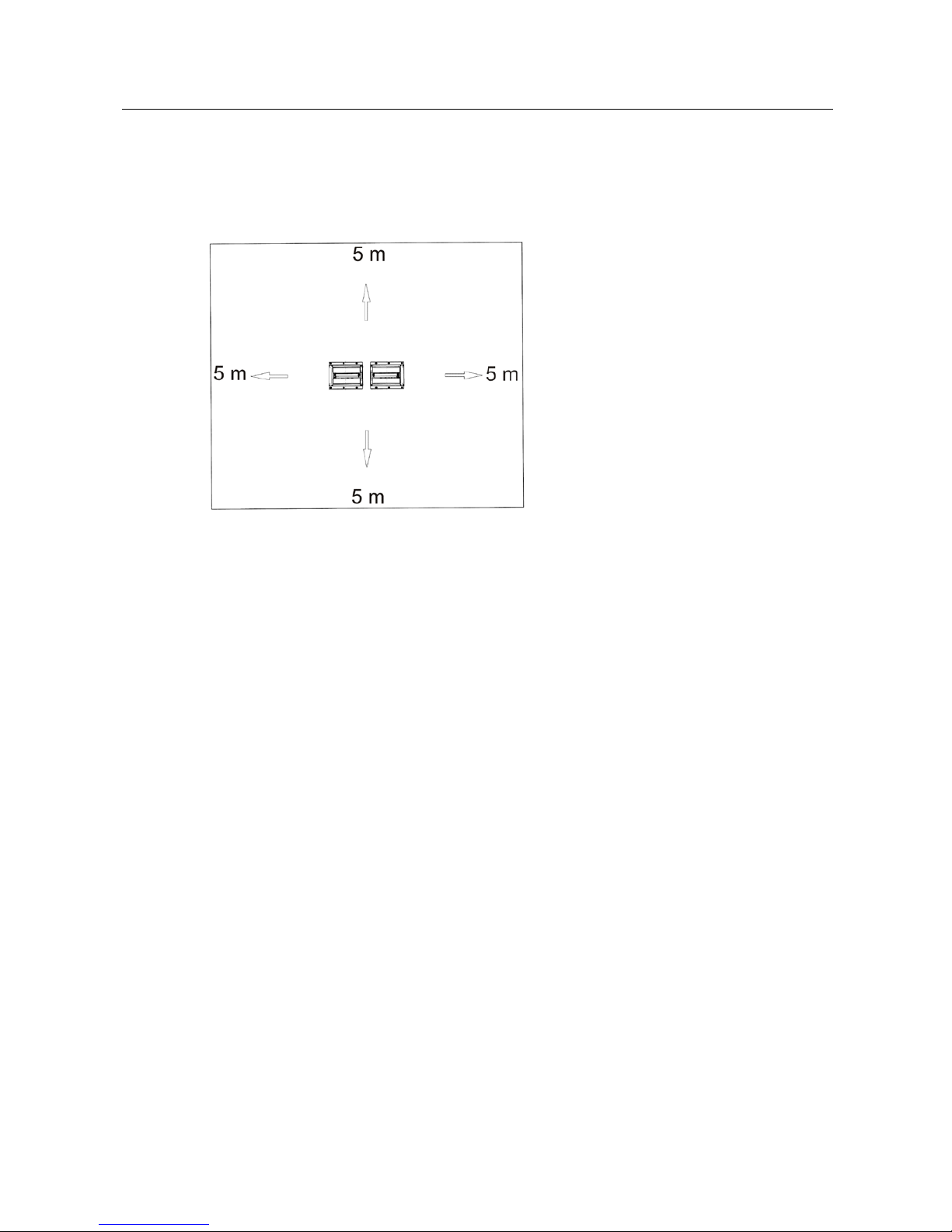
During brake tester operation no persons are allowed in the danger zone:
5 (five) meters
around the roller set in all directions.
Pos: 19 /Technische Dokumentation/Prüf- und Sicherheitstechnik/00 BPS Alle/Inhalte/Sicherheit/Inhalt: Gefahrenzone - 5m Abstand (Bild) BPS @ 19\mod_1266938260034_0.docx @ 784017 @ @ 1
Pos: 20 /Technische Dokumentation/Alle Geräte/Überschriften/Überschriften 1.1/S/Überschrift 1.1: Sicherheitsvorschriften für Servicearbeiten @ 6\mod_1174482270640_75.docx @ 76850 @ 2 @ 1
1.7
Safety Instructions for Servicing
Pos: 21 /Technische Dokumentation/Prüf- und Sicherheitstechnik/00 BPS Alle/Inhalte/Sicherheit/Inhalt: Sicherheitsvorschriften für Servicearbeiten BPS_12pt @ 26\mod_1326700977270_75.docx @ 1505581 @ @ 1
• Service work shall only be done by MAHA service technicians or authorized
service partners.
• Work on electric parts of the system shall only be done by trained electricians.
• The main switch must be switched off and secured against restart before doing
repair, maintenance and set-up work.
• Fire danger due to rubber abrasion on the roller set. Clean regularly. Remove
abrasion before maintenance work.
• The main switch must be secured and if necessary the motor protection switch
turned off when doing work in the roller set.
• When working on the control cabinet or on the roller sets pay attention to the
heating (optional) or hot parts.
• Immediately turn off the tester when it starts up unintentionally. Contact the
service department.
Pos: 22 /Technische Dokumentation/Alle Geräte/Überschriften/Überschriften 1.1/S/Überschrift 1.1: Sicherheitseinrichtungen @ 6\mod_1174483324765_75.docx @ 77103 @ 2 @ 1
1.8
Safety Features
Pos: 23 /Technische Dokumentation/Prüf- und Sicherheitstechnik/00 BPS Alle/Inhalte/Sicherheit/Inhalt: Sicherheitseinrichtungen (Text) BPS_12pt @ 26\mod_1326701513692_75.docx @ 1505625 @ @ 1
The safety features (partly optional) are to be inspected regularly by an authorized
service technician. Official guidelines must be followed at all times.
The equipment
shall not be operated when the safety features are defective!
•
Lockable Main Switch
Serves as normal On and Off switch for the equipment and as emergency switch.
The switch can be padlocked to protect it against unauthorized usage.
•
Emergency Switch
Page 8
8
BA022401-en
Is used for quick switch-off during operation. Interrupts the power supply to the
equipment.
•
Startup Monitoring
Prevents the rollers from starting up in case the wheels are blocked (seized
bearings, jammed brake pads). This feature helps prevent the vehicle tyres from
being damaged.
•
Sensor Rollers
The RPM difference between equipment rollers and sensor rollers determines the
slip. Both sensor rollers must be pushed down in order to start the roller brake
tester.
•
Visual and Audible Warning Devices
These must be positioned at a suitable location and must be easily seen or heard
at all times. In the event that the warning devices are defective, the brake tester
must be shut down until they are fully functional again.
•
Pit Safety
Light barrier or infrared movement sensor. If any person enters the safety area, the
brake tester is switched off.
•
Yellow-Black Marking Tape
The yellow-black marking tape around roller set and pit serves to mark out the
brake tester and nust be replaced if defective. Part # 19 6014 (Ø 38 mm) /
19 6015 (Ø 50 mm).
•
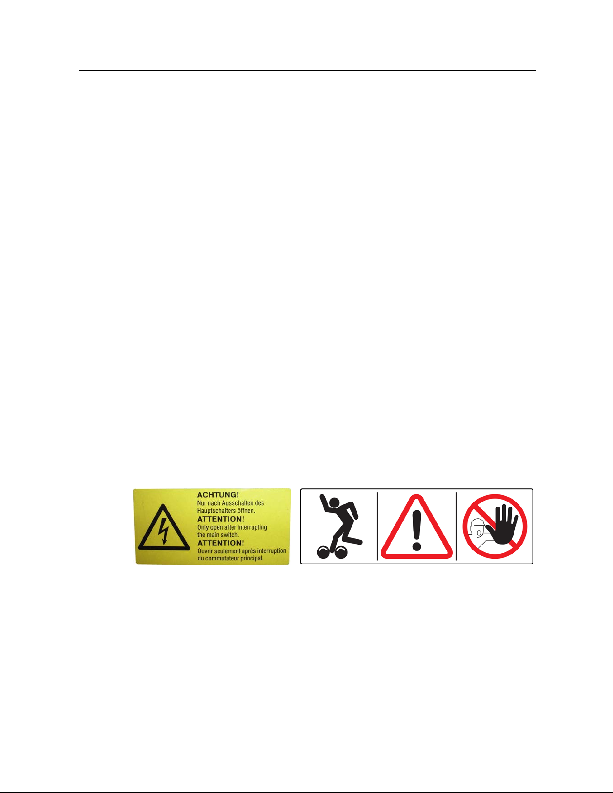
Warning and Information Labels
Warning and information labels are attached to the equipment. These must not be
changed or removed and must be replaced if unreadable (see below for part
numbers).
Pos: 24 /Technische Dokumentation/Prüf- und Sicherheitstechnik/00 BPS Alle/Inhalte/Sicherheit/Inhalt: Sicherheitseinrichtungen/Aufkleber (Bilder) BPS @ 23\mod_1297085082534_0.docx @ 971558 @ @ 1
54 2132 54 2683
Pos: 25 /Technische Dokumentation/Alle Geräte/Überschriften/Überschriften 1.1/Z/Überschrift 1.1: Zubehör @ 7\mod_1197021536541_75.docx @ 136790 @ 2 @ 1
1.9
Accessories
Pos: 26 /Technische Dokumentation/Alle Geräte/Inhalte/Sicherheit/Inhalt: Zubehör_12pt @ 25\mod_1324457135414_75.docx @ 1139114 @ @ 1
The equipment shall be operated only with accessories which have been
approved or permitted by MAHA.
Pos: 27 /Technische Dokumentation/Alle Geräte/Überschriften/Überschriften 1.1/V/Überschrift 1.1: Verhalten bei Unfällen @ 19\mod_1267177245337_75.docx @ 794600 @ 2 @ 1
1.10
What to Do in the Event of an Accident
Pos: 28 /Technische Dokumentation/Alle Geräte/Inhalte/Sicherheit/Inhalt: Verhalten bei Unfällen_12pt @ 34\mod_1381128863435_75.docx @ 1837175 @ @ 1
• The injured person is to be removed from the danger area. Find out where
dressing and bandages are kept. Seek first-aid.
Page 9

9
BA022401-en
• Provide first-aid (stop bleeding, immobilise injured limbs), report the accident
and seal off the accident site.
• Immediately report any accident to your supervisor. Make sure a record is kept
of every occasion first-aid is provided, e.g. in an accident book.
• Remain calm and answer any questions that may arise.
Pos: 29 /-----Format-----/MANUELLER UMBRUCH Seitenumbruch @ 0\mod_11344035 77687_0.docx @ 1277 @ @ 1
Page 10

10
BA022401-en
Pos: 30 /Technische Dokumentation/Alle Geräte/Überschriften/Überschriften 1/B/Überschrift 1: Beschreibung @ 6\mod_1174482271453_75.docx @ 76889 @ 1 @ 1
2
Description
Pos: 31 /Technische Dokumentation/Alle Geräte/Überschriften/Überschriften 1.1/A/Überschrift 1.1: Allgemeines @ 6\mod_1182865005781_75.docx @ 97736 @ 2 @ 1
2.1
General Information
Pos: 32 /Technische Dokumentation/Prüf- und Sicherheitstechnik/02 Rollen-BPS Pkw/2401 MBT 2100/BA/Inhalt: 0224 Beschreibung Allg @ 28\mod_1333529921514_75.docx @ 1577877 @ @ 1
This brake tester belongs to the group of roller brake testers. This class includes
two different measuring methods to record brake forces:
• the testing of drive torque or
• the testing of drive power
The former is applied in this brake tester. It consists of a proven roller set and an
open-ended electronic system based on a processor board with an integral
operating system.
Pos: 33 /Technische Dokumentation/Prüf- und Sicherheitstechnik/00 BPS Alle/Inhalte/Inhalt: Allgemeines zur Bremsprüfung_12pt @ 27\mod_1327392687866_75.docx @ 1513207 @ @ 1
General Information about Brake Testing
To avoid skidding it is important that the brake forces of the individual wheels of
one axle are the same. Just as important is the minimum brake torque for each
individual wheel, so that when braking no vehicle brake is overburdened.
Consequently, each wheel is tested individually on the brake tester.
For measuring the brake force, a static and a dynamic method are available. Using
the static method the force necessary to rotate a wheel which is positioned on a
plate, with applied brakes is determined. The dynamic method is more practice
orientated - whereby the wheel is brought up to a predetermined RPM by the
motor driven roller set and then the brakes are applied. A sensor roller measures
the wheel revolutions. A comparison of the drive roller RPM to the sensor roller
RPM determines how large the slippage is. For safety reasons, all MAHA brake
testers automatically interrupt the brake test at a slippage of approximately 30%.
The measurement principle is the same for both methods of testing. The drive
motor is supported in a rotary fashion (motor housing not supported); without any
additional support, the drive shaft and the housing would counter rotate when
under load, depending on the force distribution. The additional support consists of
a flexible beam, on which the housing rests. The steel beam bends corresponding
to the torque produced by the motor, which the beam resists. The torque is zero
at the beginning of the static test. With the dynamic test method, the torque is just
high enough to set the drive rollers with the vehicle wheel in motion with the
brakes not applied.
A strain gauge is mounted on the transverse beam which converts the brake force
into a usable electrical value.
For this brake tester the dynamic test method is used. This method ensures the
most accurate measurement. In addition, there is simply no alternative for 4 wheel
drive brake testing.
Vehicles with
One
Driven Axle
Drive the wheel axle to be tested onto the roller set. This will push both sensors
rollers down which measure the RPM of the wheels. Now both drive motors of the
roller set will slowly accelerated to nominal speed turning both vehicle wheels
Page 11

11
BA022401-en
forward. When the drive motors have reached nominal speed a comparison is
made between the nominal drive roller speed and the sensor roller speed in order
to be able, at any time, to switch off the drive motors when a slippage of 30% is
exceeded. (This is to protect the drive motors against overload and the tires
against excessive wear.)
The READY indicator will light up, signaling that the test rig is ready to start the
brake test. During brake tests the vehicle is decelerated to a point, that at least
one sensor roller exceeds 30% slippage and the drive motors are switched off.
4-Wheel Drive Vehicles
On non-permanent 4-wheel drive vehicles the brakes are tested with the 4-wheel
drive switched off, just like vehicles with only one drive axle.
Principle of 4 Wheel Drive
On 4-wheel drive vehicles the torque applied to the drive shaft is evenly distributed
to all four wheels, i.e. a quarter of the total torque will be applied to each wheel.
The same applies for the brake torques that arise when braking. When testing 4
wheel drive vehicles it must therefore be ensured that no brake torque will be
transferred from one vehicle wheel to the other. This is accomplished if no torque
is applied to the drive shaft of the differential during the brake test.
The following example will explain this in detail:
In order to simulate a defective brake, one brake is disabled. Now only one brake
of the axle to be tested is enabled. If the brake test is done on a standard test
stand where the torque is not eliminated from the drive shaft, the same force
applies to the strain gauges of both drive motors, i.e. the same brake torque will
be indicated. This would lead to the false assumption that the brakes are fully
intact. If the test was conducted correctly, no brake torque would be indicated for
the wheel with the disabled brake and the actual brake torque applied to the other
wheel would appear.
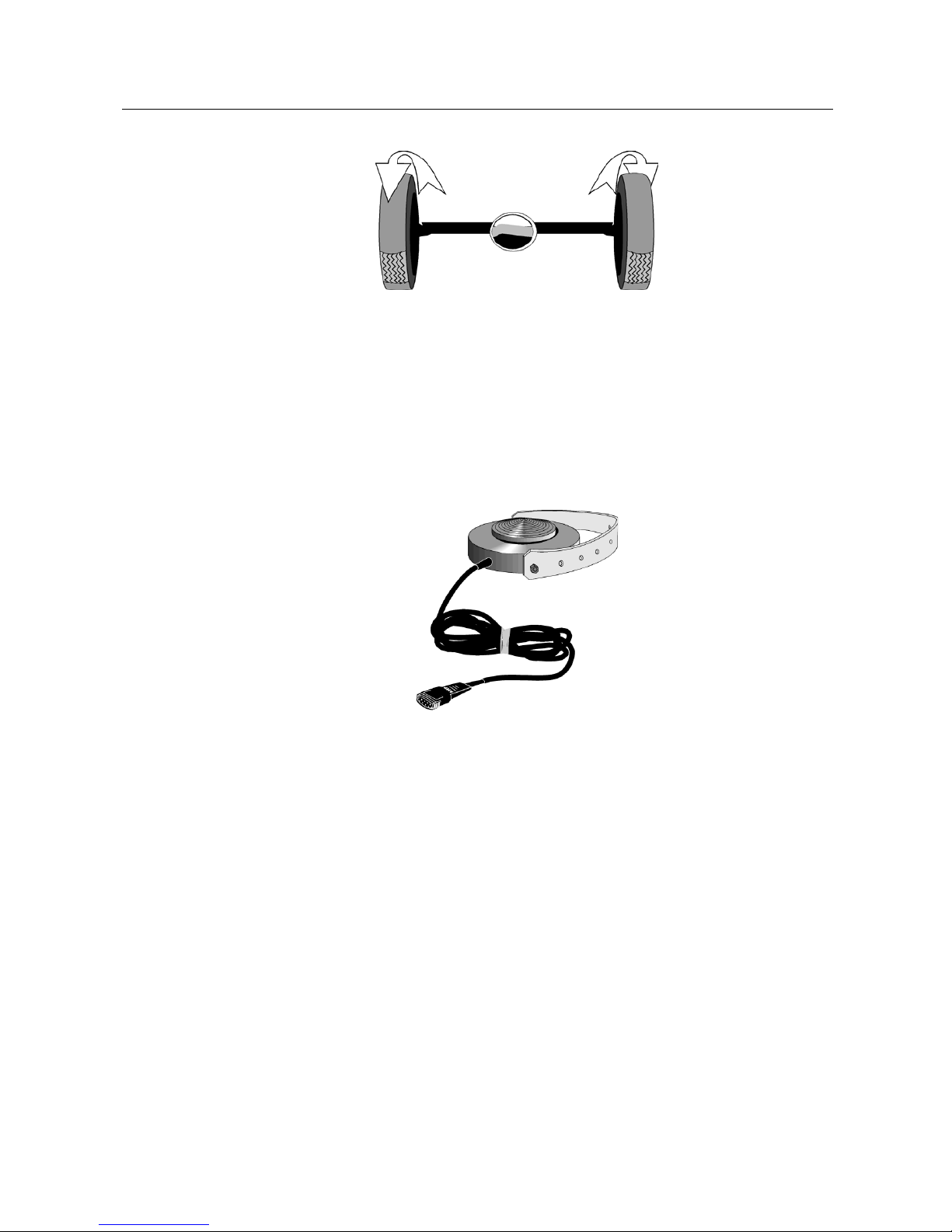
If both wheels of the axle to be tested are rotating forward during the brake test,
the vehicle will be lifted out of the test rig, as torque is transferred by the drive
shaft to the wheels of the other vehicle axle. To prevent this, the wheels counter
rotate with the same RPM, one vehicle wheel is driven in forward direction and the
other wheel in reverse direction. This eliminates the torque built-up in the
differential against the drive shaft and transmission of torque to the other vehicle
axle.
Page 12
12
BA022401-en
As the brake characteristics depend on the rotating direction of the wheels (the
brake linings and brake drums are ground in forward direction), only the brake
torque of the wheel rotating in forward direction is measured. For this reason, the
brake test has to be done separately for each wheel.
In order to obtain a reliable comparision between the brake forces of both wheels
of the same axle, the same pedal force will have to be applied at the brake test of
the left and right wheel. To accomplish this, a pedal force meter can be connected
to the vehicle's brake pedal.
It is also possible to measure the current pressure Pm of the hydraulic brake by
means of a pressure sensor.
Testing of various 4-wheel drive types
There are three different types of 4-wheel drives:
a) Disengageable drive shaft leading to the differential
b) Viscous clutch (VC) in the drive shaft leading to the differential
c) Rigid drive shaft between the differentials
a) Disengageable drive shaft leading to the differential
On vehicles equipped with non-permanent 4-wheel drive, the brakes are tested
with the 4-wheel drive switched off, just like vehicles with only one drive axle.
b) Viscous clutch (VC) in the drive shaft leading to the differential
There are two different viscous clutch types. The soft viscous clutch has a
higher torsibility (viscosity) than the hard viscous clutch, therefore no torque is
transferred to the other wheels when the drive shaft rotation is low.
Page 13
13
BA022401-en
As described above, brake tests on 4-wheel drive vehicles are feasible if both
wheels on the same axle counter-rotate at the same speed. As, in practice, the
circumference of the left and right wheel is not exactly the same due to different
tire tread depths and uneven tire pressure, the RPM of the two drive motors is
normally different. Therefore the drive motors must control their speed in order to
obtain the same RPM for both wheels.
Approximately the same speed of the roller set drive motors will be sufficient for a
4-wheel drive vehicle having a soft viscous clutch in the drive shaft as no brake
torque is transferred by the viscous clutch when the drive shaft rotation is low.
Therefore the speed control of the drive motors alone will be sufficient in this
case.
Contrary to the above, when testing the brakes of 4-wheel drive vehicle having a
hard viscous clutch in the drive shaft, both wheels on the same axle must rotate
synchronously during the brake test, as the clutch viscosity is so low that even the
slowest rotation of the drive shaft will transfer brake torque to the other wheels.
c) Rigid drive shaft between the differentials
To perform a brake test on a 4-wheel drive vehicle having a rigid drive shaft, the
wheel rotations must be exactly controlled in such a way that no brake torque
can be transferred by the drive shaft.
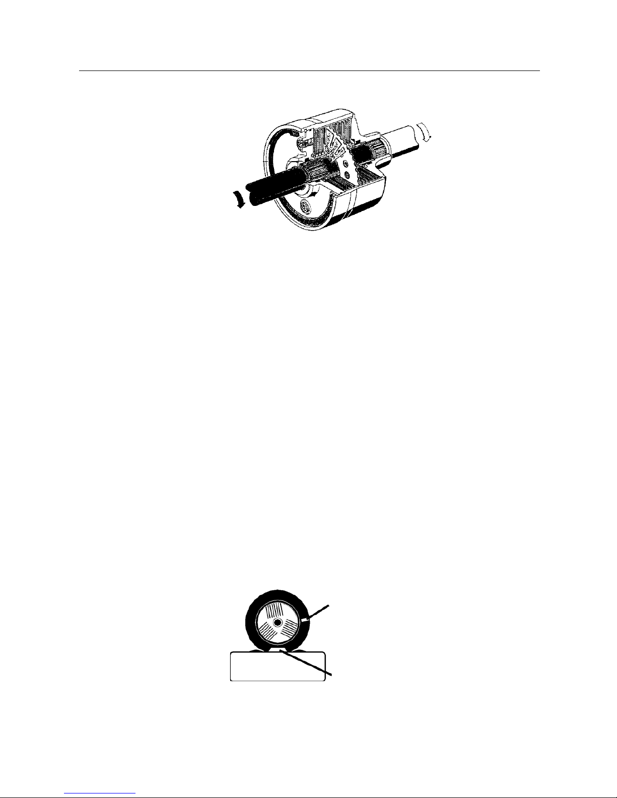
Controlling the synchroneous rotation of the wheels
In order to control synchronous rotation of the wheels, reflector strips are fastened
to the sides of the wheels which trigger a signal via two photo-electric cells,
mounted on the side of the roller set.
Reflector strips
Light barrier
Page 14

14
BA022401-en
On vehicles equipped with a rigid drive shaft or with a hard
viscous clutch the wheels cannot be individually turned. If one
vehicle wheel is turned forward in the roller set, the other wheel
(on the same axle) will be turning backwards in a synchronous
manner. If one wheel is turned slowly in forward or backward
direction, one will note that the other wheel starts turning with a
little delay. This slight delay in following the other wheel to turn is
caused by the gear play (backslash of teeth) inside of the
differential.
Tooth play
To perform a brake test on a 4-wheel drive vehicle having a rigid drive shaft, the
wheel rotation must be controlled in such a way that no brake torque can be
transferred by the drive shaft. This is achieved by staying within the gear play of
the differential during the brake test. The differential will be in a "balance" state.
To be able to effectively use this, the exact backlash of teeth is assessed in a
learning mode:
Initially the left drive motor will be switched on to accelerate the left vehicle wheel
to nominal speed. As the right drive motor is switched off and thus running free,
the left wheel is dragging the right wheel along. The flanks of a tooth in the
differential touch each other on one side. Now the first limit position of gear play is
measured by the reflector strips and the photo electric cells. The procedure is now
reversed, the left drive motor of the roller set is switched off and the right vehicle
wheel is accelerated to nominal speed. This time the left wheel is dragged along
and in the differential the flanks of teeth touch each other on the opposite side.
The second limit position of the gear play will now be measured. Out of the two
measured limit positions the center of gear play is calculated. This "center of gear
play" is used to control the rotation of wheels during the brake test.
During the brake test, both drive motors are accelerated to a speed where the
"center of gear play" is reached. One vehicle wheel will rotate forward, the other in
opposite direction. As soon as the nominal speed is reached by both wheels, and
no brake torque is being transferred to the drive shaft, brake testing may be
started.
As with standard vehicles, the drive motors will be switched off if excessive slip
occurs.
Pos: 34 /-----Format-----/MANUELLER UMBRUCH Seitenumbruch @ 0\mod_11344035 77687_0.docx @ 1277 @ @ 1
Page 15

15
BA022401-en
Pos: 35 /Technische Dokume ntation/ Alle Ger äte/Üb ersc hriften/ Überschr iften 1.1/T/ Überschrift 1. 1: Technische Daten @ 7\mod_1184075526343_75.docx @ 99711 @ 2 @ 1
2.2
Specifications
Pos: 36 /Techn ische Dokum ent atio n/Brem spr üftec hnik/ MBT-S ERIE S/022 401 MBT 2100/BA/ Inhal t: 022 4 Techn ische Da ten @ 54\m od_1530857364702_75.docx @ 3042908 @ @ 1
Standard
Option
Axle load (drive-over) max. [kg] 3000 4000 / 5000
Drive power [kW] 2 x 3 2 x 4
Test speed [km/h] 3 5
Measurement range [kN] 2 x 0…6 2 x 0…8
Display accuracy
2 % of the measurement range
end value
2 % Difference left – right
Track width min….max. [mm] 780…2200 780…2800
Roller diameter [mm] 202
Test stand dimensions [mm]
Height 280
Width 680
Length 2320 2925
Voltage supply [V] 3~ 400 3~ 230
Frequency [Hz] 50/60 50/60
Fuse (slow) [A] 16…25
Roller
friction
Dry Steel / synthetic ca. 0.9 / ca. 0.9
wet Steel / synthetic ca. 0.7 / ca. 0.8
Pos: 37 /-----For ma t-----/MAN UE LLE R UM BR UCH Se iten umb ru ch @ 0\mod_1134403577687_0.docx @ 1277 @ @ 1
Page 16

16
BA022401-en
Pos: 38 /Technische Dokumentation/Alle Geräte/Überschriften/Überschriften 1/B/Überschrift 1: Bedienung @ 6\mod_1174482271218_75.docx @ 76877 @ 1 @ 1
3
Operation
Pos: 39 /Technische Dokumentation/Alle Geräte/Überschriften/Überschriften 1.1/D/Überschrift 1.1: Display @ 8\mod_1203421747708_75.docx @ 147611 @ 2 @ 1
3.1
Display
Pos: 40 /Technische Dokumentation/Prüf- und Sicherheitstechnik/02 Rollen-BPS Pkw/2401 MBT 2100/BA/Inhalt: 0224 Display (Bild) @ 24\mod_1304407371911_0.docx @ 1002463 @ @ 1
Pos: 41 /-----Format-----/MANUELLER UMBRUCH Seitenumbruch @ 0\mod_11344035 77687_0.docx @ 1277 @ @ 1
Page 17

17
BA022401-en
Pos: 42 /Technische Dokumentation/Prüf- und Sicherheitstechnik/02 Rollen-BPS Pkw/2401 MBT 2100/BA/Inhalt: 0224 Display (Text) @ 28\mod_1333530151434_75.docx @ 15779 65 @ @ 1
A Differential display
Read the difference between the right and left-hand
brake value in % on the differential display. The
differential display is only triggered after a fixed total
brake force is exceeded.
B Power on lamp
The test stand is active when the lamp above this
symbol is lit.
C Brake Front Axle / Parking Brake / Rear Axle
D Print
E Ready lamp
When the lamp above this symbol lights up, the
brake pedal/parking brake can be operated.
F
Automatic 4WD
recognition
G Motorcycle
H Delete
I
Remote control
(optional)
In course of the brake test with remote control the
lamp shows the following signals:
1st-Interval front axle; 2nd-Interval parking
brake; 3rd-Interval rear axle;
permanent light Measurement value available,
print possible; permanent blinking New vehicle.
Pos: 43 /-----Format-----/MANUELLER UMBRUCH Seitenumbruch @ 0\mod_11344035 77687_0.docx @ 1277 @ @ 1
Page 18

18
BA022401-en
Pos: 44 /Technische Dokumentation/Alle Geräte/Überschriften/Überschriften 1.1/F/Überschrift 1.1: Fernbedienung @ 7\mod_1184152042500_75.docx @ 99994 @ 2 @ 1
3.2
Remote Control
Pos: 45 /Technische Dokumentation/Alle Geräte/Überschriften/Überschriften ohne Nummerierung/Überschrift: > RECO 1 @ 21\mod_1277893050057_0.docx @ 862443 @ @ 1
RECO 1
Pos: 46 /Technische Dokumentation/Prüf- und Sicherheitstechnik/Archiv/Z2 Fernbedienungen/2601 RECO 1/TI/Inhalt: E126 Fernbedienung RECO 1 (Bild) @ 21\mod_1277808734534_0.docx @ 861868 @ @ 1
Pos: 47 /Technische Dokumentation/Prüf- und Sicherheitstechnik/Archiv/Z2 Fernbedienungen/2601 RECO 1/TI/Inhalt: E126 Fernbedienung RECO 1 (Text)_12pt @ 27\mod_1327394842267_75.docx @ 1513653 @ @ 1
A
Motors Off
B
Start Motor left
C
Start Motor right / Start Ovality test
D
Menu item upwards
E
Confirm
F
Menu item downwards
Pos: 48 /-----Format-----/MANUELLER UMBRUCH Seitenumbruch @ 0\mod_11344035 77687_0.docx @ 1277 @ @ 1
A B D C E
F
Page 19

19
BA022401-en
Pos: 49 /Technische Dokumentation/Alle Geräte/Überschriften/Überschriften ohne Nummerierung/Überschrift: > IFB / FFB @ 21\mod_1277892982039_0.docx @ 862403 @ @ 1
IFB / FFB
Pos: 50 /Technische Dokumentation/Prüf- und Sicherheitstechnik/02 Rollen-BPS Pkw/2301 MBT LON/BA/Inhalt: 0223 Fernbedienung FFB / IFB (Bild) @ 21\mod_1277121814678_0.docx @ 858773 @ @ 1
Pos: 51 /-----Format-----/MANUELLER UMBRUCH Seitenumbruch @ 0\mod_11344035 77687_0.docx @ 1277 @ @ 1
S T D G H L Q J I K M N P
O
R
Page 20

20
BA022401-en
Pos: 52 /Technische Dokumentation/Prüf- und Sicherheitstechnik/02 Rollen-BPS Pkw/2301 MBT LON/BA/Inhalt: 0223 Fernbedienung FFB / IFB (Tabelle) @ 27\mod_1327394916024_75.docx @ 1513697 @ @ 1
Key
Function
D
F4 Start Ovality test
H
F8 Pointer stop
I
F9 Store Front axle
J
F10
Store Parking brake
Re-display MSD measurement value
K
F11 Store Rear axle
L
F12 Auto OFF
G
F7 Start Print menu
M
* Confirm
N
#
Select Sensor
Quit Noise detection
O
Program 1 key
P
Shift key
Q
Motor Off left
R
Motor On right
S
Motor On left
Pos: 53 /Technische Dokumentation/Alle Geräte/Überschriften/Überschriften 1.1/P/Überschrift 1.1: Prüfablauf @ 8\mod_1200574029101_75.docx @ 140824 @ 2 @ 1
3.3
Test Procedure
Pos: 54 /Technische Dokumentation/Prüf- und Sicherheitstechnik/02 Rollen-BPS Pkw/2401 MBT 2100/BA/Inhalt: 0224 Prüfabläufe @ 28\mod_1333530467681_75.docx @ 1578009 @ @ 1
Following test procedures are available:
• Standard mode without remote control
• Standard mode automatic 4 wheel-drive recognition
• Standard mode blink mode
• Standard mode Reco 1-procedure
• Standard mode Reco 1-4 wheel drive procedure
• Standard mode motorcycle procedure
• Standard IFB mode with motorcycle
• Standard IFB mode with 4 wheel drive
• Standard IFB mode procedure
• NL mode with IFB
• NL mode with Reco 1
• NL mode without remote control
Page 21

21
BA022401-en
• NL mode wheel circumference
Pos: 55 /Technische Dokumentation/Alle Geräte/Überschriften/Überschriften 1.1.1/S/Überschrift 1.1.1: Standard-Mode ohne Fernbedienung @ 24\mod_1305103755925_75.docx @ 1005733 @ 3 @ 1
3.3.1
Standard Mode without Remote Control
Pos: 56 /Technische Dokumentation/Prüf- und Sicherheitstechnik/02 Rollen-BPS Pkw/2401 MBT 2100/BA/Inhalt: 0224 Standard Mode ohne Fernbedienung neu @ 24\mod_130441871 8210_75.docx @ 10029 53 @ @ 1
Without remote control
MBT – test flow without remote control
Drive on to RS
Automatic roller set
Ready for braking, Light signal on
Brake up to slip or release before.
Stop rollers!
The pointers go to the max. brake value
The rollers start after 2 seconds again, pointers
do to zero and/or roller resistance.
Axle change and new measurement can start.
Page 22

22
BA022401-en
Pos: 57 /Technische Dokumentation/Alle Geräte/Überschriften/Überschriften 1.1.1/S/Überschrift 1.1.1: Standard-Mode Automatische Allraderkennung @ 24\mod_1305103860376_75.docx @ 1005763 @ 3 @ 1
3.3.2
Standard Mode Automatic 4-Wheel Drive Recognition
Pos: 58 /Technische Dokumentation/Prüf- und Sicherheitstechnik/02 Rollen-BPS Pkw/2401 MBT 2100/BA/Inhalt: 0224 Standard Mode Automatische Allraderkennung neu @ 24\mod_13044216 32389_75.do cx @ 1002983 @ @ 1
Without remote control
Automatic 4 wheel-drive recognition
(Drive Control Pro)
Display is optional
Drive on to RS
Automatic roller start
INFO
After 1X o 2X (DC PRO) start up monitoring the
test stand switches into 4 wheel drive mode.
(4x4 LED lights up)
Left-hand wheel rotates in test
direction, the right-hand wheel
in the opposite direction.
Ready for braking when light signal on.
Brake until slip limit or release before. Pay attention:
If the brake value of 500N is not
exceeded within 10 seconds after roller
start, the wheel measurement is stopped
and the right-hand side automatically
started. If the 500N is not exceeded here
either, the rollers stop and an axle change
must be done.
Rollers stop!
Max. brake force is displayed on the respective
test side.
INFO
After 2 seconds the rollers start again
automatically to test the second side.
Right-
hand wheel rotates in test direction,
the left-hand wheel in the opposite
direction.
After testing the left and right-hand side the
pointers remain on the max. value. The rollers
do not start up again.
Do axle change.
Pos: 59 /Technische Dokumentation/Alle Geräte/Überschriften/Überschriften 1.1.1/S/Überschrift 1.1.1: Standard-M
ode Blink-Modus @ 24\mod_1305105336580_75.do cx @ 1005793 @ 3 @ 1
Page 23

23
BA022401-en
3.3.3
Standard Mode Blink Mode
Pos: 60 /Technische Dokumentation/Prüf- und Sicherheitstechnik/02 Rollen-BPS Pkw/2401 MBT 2100/BA/Inhalt: 0224 Standard Mode Blink Modus neu @ 24\mod_1304490896036_75.docx @ 1003023 @ @ 1
MBT-test procedure with Reco 1 and Drucker
Drive on to roller set
Status lamp optical procedure
FA: 1 blink -»- Pause
Automatic roller start PB: 2 blinks -»- Pause
RA: 3 blinks -»- Pause
Lights up permanently: print possible.
Activate pointer stop
Permanent quick blinking: delete
measurement
Manual Auto OFF:
Measurement completion
if necessary.
Light blinks for axle measurement
Type of axle
change possible
using arrow up or
downt. (FA, PB,
RA)
Ready for braking when LED lit
Brake up to slip or release before
Rollers stop !
Pointers go to max. brake value!
Repeat
measurement
possible with arrow
up once and then
down
Rollers start again. Storage possible.
Store measurement
Axle change, new measurement can start
Page 24

24
BA022401-en
Automatic print out after FA,
PB, RA (only if function
activated)
Manual print out
(only possible outside of the
roller set)
Lights up
p
ermanently
Start print out
After printing the status lamp blinks very quickly. If this is confirmed
with the blue enter key , all measurement values are deleted.
Permanent quick blinking
Pos: 61 /-----Format-----/MANUELLER UMBRUCH Seitenumbruch @ 0\mod_11344035 77687_0.docx @ 1277 @ @ 1
Page 25

25
BA022401-en
Pos: 62 /Technische Dokumentation/Alle Geräte/Überschriften/Überschriften 1.1.1/S/Überschrift 1.1.1: Standard-Mode Reco 1-Ablauf @ 24\mod_1305105402879_75.docx @ 1005823 @ 3 @ 1
3.3.4
Standard Mode Reco 1-Procedure
Pos: 63 /Technische Dokumentation/Prüf- und Sicherheitstechnik/02 Rollen-BPS Pkw/2401 MBT 2100/BA/Inhalt: 0224 Standard Mode Reco 1-Ablauf neu @ 24\mod_1304496804618_75.docx @ 1003403 @ @ 1
MBT-test procedure with Reco 1 and printer
Drive onto roller set
Automatic roller start
Axle type change
possible with arrow
up or down /FA, PB,
RA)
Ready for brakikng, when LED lights up
Brake until slip limit or release before
Rollers stop!
The pointers go to the max. brake value!
Repeat
measurement
possible with arrow
once up and down
Rollers start again. Storage possible.
Store measurement
Axle change, new measurement can start
Final evaluation after
“Auto Off“
After measurement of the rear
axle (RA) the final evaluation
follows and the printer symbol
is automa-
tically active. After printing of the blue enter key
the print out is done.
Printing is only possible outside of the roller set.!
Display x2 = Brake force total
Display x10 = deceleration in %
if a scale is present.
Page 26

26
BA022401-en
If only one axle should be
printed out, do a “Auto Off“
The final evaluation is done. Printing is now
possible.
Pos: 64 /-----Format-----/MANUELLER UMBRUCH Seitenumbruch @ 0\mod_11344035 77687_0.docx @ 1277 @ @ 1
Page 27

27
BA022401-en
Pos: 65 /Technische Dokumentation/Alle Geräte/Überschriften/Überschriften 1.1.1/S/Überschrift 1.1.1: Standard-Mode Reco 1 -Allrad-Ablauf @ 24\mod_1305105490206_75. docx @ 1005853 @ 3 @ 1
3.3.5
Standard Mode Reco 1-4-Wheel Drive
Pos: 66 /Technische Dokumentation/Prüf- und Sicherheitstechnik/02 Rollen-BPS Pkw/2401 MBT 2100/BA/Inhalt: 0224 Standard Mode Reco 1-Allrad-Ablauf neu @ 24\mod_1304504794395_75.docx @ 1003623 @ @ 1
MBT 4 WD Test Procedure with
Reco 1 and Printer
Select 4WD: (only possible outside of RS)
Scroll to 4x4 with the Motor On key. .
Confirm the mode with the enter key.
Press again to activate the measurement (FA
blinks)
Note: If the RS is not occupied within 30 sec,
there is a reset to the standard mode!
Autom. 4 WD recognition if 4x4 not pre-selected.
(DC = Drive Control)
(Wait once for start up monitoring DC Single)
(Wait twice for start up monitoring DC PRO)
Drive onto roller set
Automatic roller start
INFO
Left-hand wheel rotates in
testing direction, the righthand in the other direction.
Use arrow up or
down for axle
change. (FA, PB, RA)
Ready for braking when LED lights up.
Brake until slip or release beforehand
Note: If after roller start the brake value of 500 N is
not exceeded within 10 sec, the wheel
measurement is stopped and the right side
automatically started. If the 500 N is also not
exceeded here, the rollers stop and an axle
change must be done.
Rollers stop.
Max. brake force is displayed on the respective
test side.
To repeat measurement use arrow up
once and down again.
After change the rollers
start again. (only DC
PRO!!)
After 2 sec the rollers start again to test the 2nd
side.
Rollers stop, measurement can be saved.
Page 28

28
BA022401-en
Save measurement
Axle change, new measurement can start, or print.
Final evaluation after
"Auto Off"
After measuring the rear axle
(RA) the final evaluation is
done and the printer symbol
is automatically active.
The printout appears after pressing the blue
Enter key .
Printing is only possible outside of the roller set!
Display x 2 = Brake force total.
Display x 10 = Deceleration in %
if weighing machine is available.
If only one axle is to be
printed an "Auto Off" must
be done. Then the final
evaluation is done.
Printing is now possible.
After confirming the waste
basket with Enter
the measurement is
deleted.
Pos: 67 /-----Format-----/MANUELLER UM BRUCH Seitenumbruch @ 0\mod_1134403577687_0. docx @ 1277 @ @ 1
Page 29

29
BA022401-en
Pos: 68 /Technische Dokumentation/Alle Geräte/Überschriften/Überschriften 1.1.1/S/Überschrift 1.1.1: Standard-Mode Motorrad-Ablauf @ 24\mod_1305105535867_75.docx @ 1005883 @ 3 @ 1
3.3.6
Standard Mode Motorcycle Procedure
Pos: 69 /Technische Dokumentation/Prüf- und Sicherheitstechnik/02 Rollen-BPS Pkw/2401 MBT 2100/BA/Inhalt: 0224 Standard Mode Motorrad-Ablauf neu @ 24\mod_1304679213084_75.docx @ 1004263 @ @ 1
MBT-Motorcycle test procedure with Reco 1
(test only possible on left-hand roller set)
Left motorcycle:
Scroll to motorcycle mode with the Motor-On-
key . Confirm the mode using the enter key.
Pay attention: If the RS is not occupied within
30 sec. there is a reset to the standard mode!
FA blinks for axle measurement
Left-side RS occupied
Start Left-side with RC
Timer runs out (left-hand pointer
display)
Automatic roller start after timer run out. (Left
pointer goes to zero in seconds intervals. Now
the motor starts.)
Ready for braking when LED lights up
Brake until slip or release beforehand
Rollers stop
Pointer moves to the max. brake value!
Measurement is automatically stored.
Axle change , new measurement can start or print.
Page 30

30
BA022401-en
Final evaluation
After measuring the rear axle (RA) the final
evaluation is done and the printer symbol is
automatically active. The print out appears
after pressing the blue Enter key .
Printing is only possible outside of the roller
set!
Display x 2 = Brake force total
Display x 10 = decleration in %
If scale is available.
After confirming the waste basket with Enter
the measurement is deleted.
Pos: 70 /-----Format-----/MANUELLER UMBRUCH Seitenumbruch @ 0\mod_11344035 77687_0.docx @ 1277 @ @ 1
Page 31

31
BA022401-en
Pos: 71 /Technische Dokumentation/Alle Geräte/Überschriften/Überschriften 1.1.1/S/Überschrift 1.1.1: Standard-IFB-Mode Motorrad @ 24\mod_1305105592167_75.docx @ 1005913 @ 3 @ 1
3.3.7
Standard IFB Mode Motorcycle
Pos: 72 /Technische Dokumentation/Prüf- und Sicherheitstechnik/02 Rollen-BPS Pkw/2401 MBT 2100/BA/Inhalt: 0224 Standard IFB Mode Motorrad neu @ 24\mod_1305018917823_75.docx @ 1005053 @ @ 1
MBT-Motorcycle test procedure with IFB
(test only possible in left-hand roller set)
Select motorcycle:
Scroll to motorcycle mode with the motor-on-
key. Use star key to confirm the mode.
Pay attention: if the roller set is not occupied
within 30 sec. There is a reset back to Standard
mode!
FA blinks for axle measurement
Drive on to left roller set side
Start left side with the remote control
Timer runs out (left-han
d pointer
display)
Automatic roller start after timer expires. (Left-
hand pointer moves in seconds to zero. Now
the motor starts)
Ready for braking when LED lights up
Brake up to slip limit or release before
Rollers stop
The pointer goes to the max. brake value!
Measurement is automatically stored after 5 seconds.
Axle change, new measurement can start or print
Manual Auto OFF!
e.g. printing of only one
axle test.
Page 32

32
BA022401-en
Final evaluation
After measurement of the RA the final
evaluation follows. After pressing the key the
print out follows.
Printing is only possible outside of the roller
set!
Display 2 times= Brake force total.
Display x10 = deceleration in %
if a scale is present.
Delete measurement with
+
or drive onto anew.
Pos: 73 /-----Format-----/MANUELLER UMBRUCH Seitenumbruch @ 0\mod_11344035 77687_0.doc x @ 1277 @ @ 1
Page 33

33
BA022401-en
Pos: 74 /Technische Dokumentation/Alle Geräte/Überschriften/Überschriften 1.1.1/S/Überschrift 1.1.1: Standard-IFB-Mode mit Allrad @ 24\mod_1305105637282_75.docx @ 1005943 @ 3 @ 1
3.3.8
Standard IFB Mode with 4-Wheel Drive
Pos: 75 /Technische Dokumentation/Prüf- und Sicherheitstechnik/02 Rollen-BPS Pkw/2401 MBT 2100/BA/Inhalt: 0224 Standard IFB Mode mit Allrad neu @ 24\mod_1304934632233_75.do cx @ 1004463 @ @ 1
MBT-4 wheel drive test procedure with Reco 1
and printer
Select 4 wheel drive:
Use the motor-on-key scroll to 4x4.
Confirm the mode with the star key.
Pay attention: if the roller set is not occupied
within 30 sec. then it returns to standard mode !
Autom. 4 wheel drive if 4x4 not pre-selected.
(Drive-Control Pro)
(wait 2x start-up monitoring)
Drive on to roller set
Automatic roller start
INFO
Left-hand wheel rotates in
test direction, the righthand one in the opposite
direction.
Ready for braking when LED lights up
Brake until slip limit or release before
Pay attention: If the brake value of 500N is not
exceeded within 10 seconds after roller start, the
wheel measurement is stopped and the right-hand
side automatically started. If the 500N is not
exceeded here either, the rollers stop and an axle
change must be done.
Rollers stop!
The pointer goes to the max. brake value!
Repeat
measurement
possible. Delete
axle measurement.
Repeat
measurement!
After 2 seconds, the rollers start again to test
the second side.
Roller stops, measurement ready for storage
Page 34

34
BA022401-en
Store: Front axle Parking brake Rear axle
Axle change! New measurement can start or
print.
Manual Auto OFF!
e.g. printing of only one axle
measurement.
Start printing.
Final evaluation
Print out is only possible outside of the roller set.
Display x2 = Brake force total
Display x10 = decleration in %
if a scale is present.
Delete measurement with
+
or drive on again.
Pos: 76 /-----Format-----/MANUELLER UM BRUCH Seitenumbruch @ 0\mod_1134403577687_0. docx @ 1277 @ @ 1
Page 35

35
BA022401-en
Pos: 77 /Technische Dokumentation/Alle Geräte/Überschriften/Überschriften 1.1.1/S/Überschrift 1.1.1: Standard-IFB-Mode @ 24\mod_1305105687623_75.docx @ 10059 73 @ 3 @ 1
3.3.9
Standard IFB Mode Procedure
Pos: 78 /Technische Dokumentation/Prüf- und Sicherheitstechnik/02 Rollen-BPS Pkw/2401 MBT 2100/BA/Inhalt: 0224 Standard IFB Mode Ablauf neu @ 24\mod_1304923911060_75.doc x @ 1004293 @ @ 1
MBT-test procedure with remote control IFB (without
LED)
Drive on to roller set
LED display is only needed when
option 4x4, motorcycle or 2nd driving
direction is present.
Automatic roller start
Ready for braking when light signal on
Activate pointer Stopp
slowly brake until slip limit or release before
Stop rollers!
the pointer goes to the max. brake value.
Roller starts again.
Storage possible!
Delete axle measurement
.
Repeat measurement
Store: Front axle Parking brake Rear axle
Axle change! New measurement can start.
Manual Auto OFF!
e.g. print of only one axle
measurement.
Page 36

36
BA022401-en
Start print
Final evaluation
Print out is only possible outside of the roller set
Display x2 = Brake force Ges.
display x10 = deceleration in %
as long as a scale is present.
Pos: 79 /-----Format-----/MANUELLER UMBRUCH Seitenumbruch @ 0\mod_11344035 77687_0.docx @ 1277 @ @ 1
Page 37

37
BA022401-en
Pos: 80 /Technische Dokumentation/Alle Geräte/Überschriften/Überschriften 1.1.1/N/Überschrift 1.1.1: NL-Mode mit IFB @ 24\mod_1305105739119_75.docx @ 1006003 @ 3 @ 1
3.3.10
NL Mode with IFB
Pos: 81 /Technische Dokumentation/Prüf- und Sicherheitstechnik/02 Rollen-BPS Pkw/2401 MBT 2100/BA/Inhalt: 0224 NL Mode mit IFB neu @ 24\mod_1305098531708_75.docx @ 1005633 @ @ 1
APK-test procedure with IFB remote control (optional pedal force meter)
Drive on to roller set
Automatic roller set
Activate pointer stop
Measurement front and rear axle Measurement parking brake
Slowly brake
Lamp blinks permanently
Ready lamp blinks once
Measurement point P1 is measured.
One wheel rotation (1WR)
Brake until slip and release brake (no
APK-procedure necessary)
Brake until slip limit
Pedal steady
Ready lamp blinks twice
Measurement point P2 is measured.
Valid APK measurement after two
wheel rotations (2WR)
Release brake or brake until slip.
Stop rollers.
The pointer goes to the last valid APK value and not
to the max. value!
The rollers start again, storing possible.
Page 38

38
BA022401-en
Store: Front axle Parking brake Rear axle
Axle change! New measurement can start or
print.
Manual Auto OFF!
e.g. print of only one axle
measurement.
Start print
Print out is only possible outside of the roller set.
Pos: 82 /-----Format-----/MANUELLER UMBRUCH Seitenumbruch @ 0\mod_11344035 77687_0.docx @ 1277 @ @ 1
Page 39

39
BA022401-en
Pos: 83 /Technische Dokumentation/Alle Geräte/Überschriften/Überschriften 1.1.1/N/Überschrift 1.1.1: NL-Mode mit Reco 1 @ 24\mod_ 1305105950239_75.doc x @ 1006033 @ 3 @ 1
3.3.11
NL Mode with Reco 1
Pos: 84 /Technische Dokumentation/Prüf- und Sicherheitstechnik/02 Rollen-BPS Pkw/2401 MBT 2100/BA/Inhalt: 0224 NL Mode mit Reco 1 neu @ 24\mod_1305094637249_75.docx @ 1005603 @ @ 1
APK-test procedure with Reco 1 and printer
Drive on to roller set
Optical Procedure
FA: blink once -»- Pause
Automatic roller start
PB: blink twice -»- Pause (no APK procedure
necessary)
RA: blink three times -»- Pause
Lights up permanently: print possible.
Activate pointer Stopp
Permanent rapid blinking: delete
measurement
Manual Auto OFF:
e.g. printing of only one
axle measurement
Pointer stop active. Light blinks
Slowly brake
Ready lamp blinks once
Measurement point P1 is measured.
One wheel rotation (1RU)
Brake up to slip
Pedal steady
Ready lamp blinks twice
Measurement point P2 is measured.
Valid APK measurement after two wheel
rotations (2WR)
Release brake or brake up to slip.
Stop rollers!
The pointers go to the last, valid APK value and
not to the max. value!
Rollers start again. Storage possible.
Page 40

40
BA022401-en
St
orage measurement
Axle change, new measurement can start
Automatic print out after
measurement of FA, PB, RA
(only when function activated)
Manual print out
(only possible outside of roller
set)
Lights
permanently
Start print out
Pos: 85 /-----Format-----/MANUELLER UMBRUCH Seitenumbruch @ 0\mod_11344035 77687_0.docx @ 1277 @ @ 1
Page 41

41
BA022401-en
Pos: 86 /Technische Dokumentation/Alle Geräte/Überschriften/Überschriften 1.1.1/N/Überschrift 1.1.1: NL-Mode ohne Fernbedienung @ 24\mod_1305106004745_75.docx @ 1006063 @ 3 @ 1
3.3.12
NL Mode without Remote Control
Pos: 87 /Technische Dokumentation/Prüf- und Sicherheitstechnik/02 Rollen-BPS Pkw/2401 MBT 2100/BA/Inhalt: 0224 NL Mode ohne Fernbedienung neu @ 24\mod_1305023457296_75.docx @ 1005123 @ @ 1
APK-test procedure without remote control
Drive on to roller set
Automatic roller start
Slowly brake
Measurement point P1 is measured.
One wheel rotation (1WR)
Ready lamp blinks
once
Brake up to slip limit, keep pedal steady.!
Measurement point P2 is measured. Valid APK
measurement after two wheel rotations. (2WR)
Ready lamp blinks
twice
Release brake or brake up to slip.
Rollers stop
The pointers go back to the last, valid APK value
and not to the max. value!
The rollers start again, pointers go back to zero.
Axle change or new measurement can start.
Pos: 88 /Technische Dokumentation/Alle Geräte/Überschriften/Überschriften 1.1.1/N/Überschrift 1.1.1: NL-Mode Radumfang @ 24 \mod_1305106043745_75.d ocx @ 1006093 @ 3 @ 1
Page 42

42
BA022401-en
3.3.13
NL Mode Wheel Circumference
Pos: 89 /Technische Dokumentation/Prüf- und Sicherheitstechnik/02 Rollen-BPS Pkw/2401 MBT 2100/BA/Inhalt: 0224 NL Mode Radumfang neu @ 24\mod_1305019677002_75.do cx @ 1005093 @ @ 1
Version control with strain gauge detuning
Switch on test stand
Pointer initialization (~10 sec)
Display of the version number e.g. 300R100
Display 5
Strain gauge detuning.
visible at pointer.
Press power on key
Test stand is ready for testing
Enter wheel circumference
Press power on key 5 sec. Zero point check
After 5 sec.
• Pointers go to 60 cm.
• Each key press increases it by 1 cm.
• Permanent pressing reduces by 2 cm.
• After 5 sec. without value change automatic
storage As confirmation the left-hand pointer
goes to the same value.
Blinks in this mode
Value is stored until new vehicle is executed!
Pos: 90 /-----Format-----/MANUELLER UMBRUCH Seitenumbruch @ 0\mod_1134403577687_0.docx @ 1277 @ @ 1
Page 43

43
BA022401-en
Pos: 91 /Technische Dokumentation/Alle Geräte/Überschriften/Überschriften 1.1/A/Überschrift 1.1: Abbremstabelle @ 8\mod_1203419773557_75.docx @ 147594 @ 2 @ 1
3.4
Deceleration Chart
Pos: 92 /Technische Dokumentation/Prüf- und Sicherheitstechnik/02 Rollen-BPS Pkw/2401 MBT 2100/BA/Inhalt: 0224 Abbremstabelle @ 28\mod_1337586480163_75.docx @ 159839 1 @ @ 1
Permiss
Axle
Load in
kg
Axle Brake Force in kN
200
50
100
300
33
67
100
400
25
50
75
100
500
20
40
60
80
100
600
17
33
50
67
83
100
700
14
29
43
57
71
86
100
800
13
25
38
50
63
75
88
100
900
11
22
33
44
56
67
78
89
100
1000
10
20
30
40
50
60
70
80
90
100
1100
9
18
27
36
45
55
64
73
82
91
100
1200
8
17
25
33
42
50
58
67
75
83
92
100
1300
8
15
23
31
38
46
54
62
69
77
85
92
100
1400
7
14
21
29
36
43
50
57
64
71
79
86
93
100
1500
7
13
20
27
33
40
47
53
60
67
73
80
87
93
100
1600
6
13
19
25
31
38
44
50
56
63
69
75
81
88
94
100
Deceleration in %
Pos: 93 /-----Format-----/MANUELLER UMBRUCH Seitenumbruch @ 0\mod_1134403577687_0.docx @ 1277 @ @ 1
Page 44

44
BA022401-en
Pos: 94 /Technische Dokumentation/Papierkorb/Überschriften/Überschrift 1: Instandhaltung @ 11\mod_1231318736629_75.docx @ 289550 @ 1 @ 1
4
Maintenance
Pos: 95 /Technische Dokumentation/Alle Geräte/Inhalte/Warnung!/Inhalt: Warnung - Hauptschalter aus bei Instandhaltung_12pt @ 26\mod_1324465229892_75.docx @ 1140563 @ @ 1
Danger! Electric shock hazard!
Before doing any maintenance work, turn off the main switch and protect it
against tampering.
Pos: 96 /Technische Dokumentation/Papierkorb/Überschriften/Überschrift 1.1: Jährliche Überprüfung @ 6\mod_1174482245718_75.docx @ 76817 @ 2 @ 1
4.1
Annual Inspection
Pos: 97 /Technische Dokumentation/Alle Geräte/Inhalte/Info!/Inhalt: Info - Jährliche Überprüfung_12pt @ 25\mod_1324460481075_75.docx @ 1139412 @ @ 1
• The maintenance interval prescribed by the manufacturer is
12 (twelve) months
.
This maintenance interval refers to normal workshop usage. If the equipment is
used more frequently or under severe operating conditions (e.g. outdoors), the
interval must be reduced accordingly.
• Maintenance work shall be done only by authorized and trained service
technicians provided by the manufacturer, licensed dealers or service partners.
• In case of non-compliance the manufacturer's warranty becomes void.
Pos: 98 /Technische Dokumentation/Papierkorb/Überschriften/Überschrift 1.1: Instandhaltung durch den Betreiber @ 6\mod_1178543544390_75.docx @ 91370 @ 2 @ 1
4.2
Maintenance by the Operator
Pos: 99 /Technische Dokumentation/Alle Geräte/Überschriften/Überschriften 1.1.1/K/Überschrift 1.1.1: Kettenspannung prüfen @ 18\mod_1254744431734_75.docx @ 457139 @ 3 @ 1
4.2.1
Checking the Chain Tension
Pos: 100 /Technische Dokumentation/Alle Geräte/Inhalte/Info!/Inhalt: Info - Wartungsintervall: Monatlich_12pt @ 26\mod_1324463913433_75.docx @ 1140268 @ @ 1
Maintenance interval: Monthly
Pos: 101 /Technische Dokumentation/Prüf- und Sicherheitstechnik/00 BPS Alle/Inhalte/Inhalt: Inst Kettenspannung (Text) IW 2/4/7/10_12pt @ 26\mod_1326874773072_75.docx @ 1511503 @ @ 1
Check the chain tension for the first time 14 working days after initial operation,
then monthly:
1 Remove cover plates from roller set.
2 Grease the chain (A) well with multi-purpose grease along its entire length.
While greasing, turn the rollers by hand.
3 Check that the chain has a slack of approx. 5 mm in either direction.
Page 45

45
BA022401-en
If the chain does not have enough tension, proceed as follows:
4 Open the fastening screws (B).
5 Tighten the tensioning screw (C) until the chain has the proper tension.
6 Retighten the fastening screws.
Brake testers with elevated roller sets: Tightening torque
500 Nm
7 Recheck the chain tension.
8 Reinstall the cover plates to the roller set.
Pos: 102 /-----Format-----/MANUELLER UMBRUCH Zeilenschaltung @ 7\mod_ 1195138965731_0.doc x @ 132177 @ @ 1
Pos: 103 /-----Format-----/ MANUELLER UMBRUCH Zeilenschaltung @ 7\mod_119 5138965731_0.docx @ 132177 @ @ 1
Pos: 104 /Technische Dokumentation/Prüf- und Sicherheitstechnik/00 BPS Alle/Inhalte/Inhalt: Inst Kettenspannung (Bilder) MBT 3x00 @ 18\mod_1254727296554_0.docx @ 456256 @ @ 1
Pos: 105 /-----Format-----/MANUELLER UMBRUCH Seitenumbruch @ 0\mod_1134403 577687_0.doc x @ 1277 @ @ 1
Page 46

46
BA022401-en
Pos: 106 /Technische Dokumentation/Papierkorb/Überschriften/Überschrift 1.1.1: Tastrollenscharniere schmieren @ 18\mod_1254744523806_75.docx @ 457166 @ 3 @ 1
4.2.2
Greasing the Sensor Roller Hinges
Pos: 107 /Technische Dokumentation/Alle Geräte/Inhalte/Info!/Inhalt: Info - Wartungsintervall: 200 h / 12 Monate_12pt @ 26\mod_1324463609793_75.do cx @ 1140170 @ @ 1
Maintenance interval: 200 hours / 12 months
Pos: 108 /Technische Dokumentation/Prüf- und Sicherheitstechnik/00 BPS Alle/Inhalte/Inhalt: Inst Tastrollen (Text) MBT 3x00/4x00/7x00_12pt @ 26\mod_1326874914374_75.docx @ 1511547 @ @ 1
Grease the sensor roller hinges every 200 (two hundred) operating hours or once
annually.
1 Remove the cover plates from the roller set.
2 Treat the greasing points (D) using a spray lubricant. Move the sensor roller up
and down.
3 Reinstall the cover plates to the roller set.
Pos: 109 /Technische Dokumentation/Prüf- und Sicherheitstechnik/00 BPS Alle/Inhalte/Inhalt: Inst Tastrollen (Bilder) MBT 3x00 @ 18\mod_1254732674783_0.docx @ 456550 @ @ 1
Pos: 110 /-----Format-----/MANUELLER UM BRUCH Seitenumbruch @ 0\mod_1134403 577687_0.do cx @ 1277 @ @ 1
Page 47

47
BA022401-en
Pos: 111 /Technische Dokumentation/Alle Geräte/Überschriften/Überschriften 1.1/F/Überschrift 1.1: Fehlercodes @ 14\mod_1240470968985_75.docx @ 366697 @ 2 @ 1
4.3
Error Codes
Pos: 112 /Technische Dokumentation/Prüf- und Sicherheitstechnik/02 Rollen-BPS Pkw/2401 MBT 2100/BA/Inhalt: 0224 Standard Mode Fehlercodes @ 28\ mod_1337586022012_75. docx @ 1598303 @ @ 1
Error
code
Description Remedy
12
Connection to multi-function
display missing
Contact service
32
Left sensor roller impulse sensor
defective
Check motor protection switch.
If o.k. contact service.
33
Both sensor roller impulse
sensors defective
Check motor protection switch.
If o.k. contact service..
34
Right sensor roller impulse
sensor defective
Check motor protection switch.
If o.k. contact service.
40
Zero point of the brake force
strain gauge outside of range
Contact service
41
Only left-hand sensor roller
pressed
Drive onto both sides of test stand.
42
Only right-hand sensor roller
pressed
Drive onto both sides of test stand.
50 Scale zero point outside of range
Roller set may not be occupied when
switching on.
51
Test stand is already occupied
when switching on.
Exit test stand with vehicle and switch
main switch off/on.
Pos: 113 /Technische Dokumentation/Alle Geräte/Überschriften/Überschriften 1.1/P/Überschrift 1.1: Pflegehinweise @ 15\mod_1245912234854_75.docx @ 395780 @ 2 @ 1
4.4
Care Instructions
Pos: 114 /Technische Dokumentation/Alle Geräte/Inhalte/Inhalt: Pflegehinweise - Alle Geräte_12pt @ 26\mod_1324468886116_75.docx @ 1141252 @ @ 1
• Periodically clean the equipment and treat it with a care product.
• Repair damage to the paintwork immediately to prevent corrosion.
• Usage of caustic cleaning agents or high pressure and steam jet cleaners may
lead to equipment damage.
Pos: 115 /Technische Dokumentation/Alle Geräte/Inhalte/Info!/Inhalt: Info - Pflegehinweise_12pt @ 26\mod_1324461215655_75.docx @ 1139602 @ @ 1
Regular care and maintenance is the key condition for functionality and long life
expectancy of the equipment!
Pos: 116 /Technische Dokumentation/Alle Geräte/Überschriften/Überschriften 1.1/E/Überschrift 1.1: Ersatzteile @ 18\mod_1255596847002_75.docx @ 474414 @ 2 @ 1
4.5
Spare Parts
Pos: 117 /Technische Dokumentation/Alle Geräte/Inhalte/Inhalt: Ersatzteile - Alle Geräte_12pt @ 26\mod_1324468768120_75.docx @ 1141219 @ @ 1
To ensure safe and reliable operation, only use original spare parts supplied by the
equipment manufacturer.
Pos: 118 /-----Format-----/MANUELLER UMBRUCH Seitenumbruch @ 0\mod_1134403 577687_0.doc x @ 1277 @ @ 1
Page 48

48
BA022401-en
Pos: 119 /Technische D okumen tation/ Alle G eräte/ Überschr iften/ Übers chrifte n 1/D/Üb erschr ift 1: Demon tage @ 19\mod _12 66336 8228 63_75.d ocx @ 74 2452 @ 1 @ 1
5
Dismantling
Pos: 120 /Te chn isch e Dok umen tation/A lle G eräte/In halte/I nhalt: Demon tage - Al le Gerä te_ 12p t @ 2 6\mod_1324466078229_75.docx @ 1140857 @ @ 1
Decommissioning and dismantling of the equipment may be done only by
specially authorized and trained personnel provided by the manufacturer, licensed
dealers or service partners.
Pos: 121 /-----F orma t-----/M ANUE LLE R UMB RUC H Z eile nsc hal tu ng @ 7\mod_1195138965731_0.docx @ 132177 @ @ 1
Pos: 122 /Technische D okumen tation/ Alle G eräte/ Überschr iften/ Übers chrifte n 1/I/ Überschrif t 1: I nhalt d er Kon form itäts erklä rung @ 22\m od_1292856748432_75.docx @ 958616 @ 1 @ 1
6
Contents of the Declaration of Conformity
Pos: 123 /Technische D okumen tation/ Alle G eräte/In halt e/Inhalt : Inha lt der K onform itätser klärung allg_ 12pt @ 26\mod_1324468436145_75.docx @ 1141120 @ @ 1
MAHA Maschinenbau Haldenwang GmbH & Co. KG
herewith declares as a manufacturer its sole responsibility to ensure that the
product named hereafter meets the safety and health regulations both in design
and construction required by the EC directives stated below.
This declaration becomes void if any change is made to the product that was not
discussed and approved by named company beforehand.
Pos: 124 /Tech nische Dok umen tati on/Br emsp rüfte chnik/ MBT- SERI ES/ 02 240 1 MB T 2 100/B A/I nha lt: 022 4 In ha lt der Ko nform itätserk lärung @ 54\mod_1530860864774_75.docx @ 3043063 @ @ 1
Model:
MBT 2100 / 2110 / 2120 / 2130
Designation:
Roller Brake Tester
Rated Axle Load 3000 kg (4000 / 5000 kg optional)
Motor Power 2 x 2.25 kW (2 x 4 kW optional)
EC Directives:
2006/42/EC; 2014/30/EU
EN Standards:
EN 12100-1/-2; EN 13850; EN 13857; EN 349; EN
60204-1; EN 61000-6-3, EN 61000-6-2
Pos: 125 /-----F orma t-----/M ANUELLE R UMBR UCH Seitenum bruc h @ 0\mod_1134403577687_0.docx @ 1277 @ @ 1
Page 49

49
BA022401-en
Pos: 126 /Te chn isch e Dok umen tation/A lle G eräte/Üb erschr iften/Üb erschr iften 1/ F/Übers chrif t 1: Fir men-Inf ormat ion @ 7\mod_ 1187 3386 25828_ 75.do cx @ 1040 47 @ 1 @ 1
7
Company Information
Pos: 127 /Technische D okumen tation/ Alle G eräte/In halt e/Inhalt : Firmen -Inf ormat ion M AHA @ 53\ mod_ 1529400378770_75.docx @ 3037518 @ @ 1
© MAHA Maschinenbau Haldenwang GmbH & Co. KG
Legal notice based on ISO 16016:
The reproduction, distribution and utilization of this document as well as the communication of its
contents to others without explicit authorization is prohibited. Offenders will be held liable for the
payment of damages. All rights reserved in the event of the grant of a patent, utility model or design.
The contents of this edition have been checked with great care. However, errors cannot be fully
excluded. Subject to technical change without notice.
Document
Document No.: BA022401-en
Approval Date: 2018-07-06
Manufacturer
MAHA Maschinenbau Haldenwang GmbH & Co. KG
Hoyen 20
87490 Haldenwang
Germany
Phone: +49 8374 585 0
Fax: +49 8374 585 590
Mail: maha@maha.de
Web: http://www.maha.de
Service
MAHA Service Center
AutomoTec GmbH
Maybachstraße 8
87437 Kempten
Germany
Phone: +49 8374 585 100
Fax: +49 8374 585 491
Mail: service@automo-tec.com
Web: http://www.maha.de/service-center.htm
=== Ende der Liste für Textm arke In halt ===
 Loading...