

Page 1

Fehler! Verwenden Sie die Registerkarte 'Start', um Name dem Text zuzuweisen, der hier angezeigt werden soll.Fehler! Verwenden Sie
die Registerkarte 'Start', um Name dem Text zuzuweisen, der hier angezeigt werden soll.Fehler! Verwenden Sie die Registerkarte
'Start', um Name dem Text zuzuweisen, der hier angezeigt werden soll.
MLS
Weight Simulators
Original Operating Instructions
BA042501-en
Pos: 1 /Technische Dokumentation/Alle Geräte/Titeltexte/Titeltext: MLS - Alle Typen (MLS+RSA) @ 34\mod_1382616637356_75.docx @ 1845413 @ @ 1
MLS 1100
Roller Set Lift MBT 2000 RS5
MLS 2100
MLS 2150
MLS 2200
MLS 2300
Pos: 2 /-----For mat-----/MANUELLER UMBRUCH Se itenumbruch @ 0\mod_1134403577687_0. docx @ 1277 @ @ 1
Roller Set Lift MBT 4000/7000 RS2/W
Page 2

2
© MAHA Maschinenbau Haldenwang GmbH & Co. KG
Legal notice based on ISO 16016:
The reproduction, distribution and utilization of this document as well as the communication of its
contents to others without explicit authorization is prohibited. Offenders will be held liable for the
payment of damages. All rights reserved in the event of the grant of a patent, utility model or design.
The contents of this edition have been checked with great care. However, errors cannot be fully
excluded. Subject to technical change without notice.
Document
Document No.: BA042501-en
Approval Date: 2019-01-14
Manufacturer
MAHA Maschinenbau Haldenwang GmbH & Co. KG
Hoyen 20
87490 Haldenwang
Germany
Phone: +49 8374 585 0
Fax: +49 8374 585 590
Mail: maha@maha.de
Web: http://www.maha.de
Service
MAHA SERVICE CENTER
AutomoTec GmbH
Maybachstraße 8
87437 Kempten
Germany
Phone: +49 8374 585 100
Fax: +49 8374 585 491
Mail: service@automo-tec.com
Web: www.automo-tec.com
BA042501-en
Page 3

3
Contents
1
Safety .................................................................................................................... 5
2
Description ............................................................................................................ 6
3
Operation ............................................................................................................... 9
4
Maintenance ........................................................................................................ 26
Pos: 5 /-----For mat-----/Inhaltsverze ichnis - 3 Ebenen @ 5\mod_1168867441046_75.docx @ 72920 @ @ 1
1.1 Introduction .............................................................................................................. 5
1.2 Symbols ................................................................................................................... 5
1.3 Intended Use ........................................................................................................... 5
1.4 Requirements on Operating and Service Personnel .................................................. 5
1.5 Safety Instructions .................................................................................................... 6
2.1 General Information .................................................................................................. 6
2.2 Design ..................................................................................................................... 7
2.2.1 Weight Simulator ...................................................................................................... 7
2.2.2 Roller Set Lift ............................................................................................................ 7
2.3 Specifications ........................................................................................................... 8
2.3.1 Weight Simulator ...................................................................................................... 8
2.3.2 Roller Set Lift ............................................................................................................ 8
3.1 Control via Desk/Power Unit (Weight Simulator only) ................................................. 9
3.2 Control via EUROSYSTEM ..................................................................................... 12
3.2.1 Weight Simulator .................................................................................................... 12
3.2.2 Roller Set Lift .......................................................................................................... 14
3.3 Cable Remote (Roller Set Lift only) .......................................................................... 18
3.4 Remote Control FFB3 ............................................................................................ 18
3.4.1 Weight Simulator .................................................................................................... 18
3.4.2 Roller Set Lift .......................................................................................................... 18
3.5 Operation of the stand-alone variant (roller set lift only) ............................................ 19
3.6 Emergency Lowering .............................................................................................. 21
3.6.1 Weight Simulator .................................................................................................... 21
3.6.2 Roller Set Lift .......................................................................................................... 21
3.7 Pneumatic Emergency Lowering for MBT 4000/7000 with Integrated Roller Set Lift 24
3.7.1 Function ................................................................................................................. 24
3.7.2 Operation ............................................................................................................... 25
4.1 Annual Inspection ................................................................................................... 26
4.2 Maintenance by the Operator ................................................................................. 26
4.3 Refilling with Hydraulic Fluid ................................................................................... 27
4.4 Spare Parts ............................................................................................................ 27
BA042501-en
Page 4

4
5
Dismantling .......................................................................................................... 30
6
Disposal ............................................................................................................... 30
7
Contents of the Declaration of Conformity ............................................................. 30
4.5 Checking and Refilling the Bladder Accumulator ..................................................... 28
Pos: 6 /-----For mat-----/MANUELLER UMBRUCH Se itenumbruch @ 0\mod_1134403577687_0. docx @ 1277 @ @ 1
BA042501-en
Page 5

5
1
Safety
1.1
Introduction
1.2
Symbols
1.3
Intended Use
1.4
Requirements on Operating and Service Personnel
Pos: 7 /Technische Dokumentation/Alle Geräte/Überschriften/Überschriften 1/S/Überschrift 1: Sicherheit @ 6\mod_1174482399906_75.docx @ 76962 @ 2 @ 1
Pos: 8 /Technische Dokumentation/Alle Geräte/Überschriften/Überschriften 1.1/E/Überschrift 1.1: Einführung @ 6\mod_1174482219062_75.docx @ 76793 @ 2 @ 1
Pos: 9 /Technische Dokumentation/Alle Geräte/Inhalte/Sicherheit/Inhalt: Einführung Sicherheit_12pt @ 25\mod_1324455248318_75. docx @ 1138886 @ @ 1
Thoroughly read this manual before operating the equipment and comply with the
instructions. Always display the manual in a conspicuous location.
Personal injury and property damage incurred due to non-compliance with these
Pos: 10 /Technische Dokumentation/Alle Geräte/Überschriften/Überschriften 1.1/S/Überschrift 1.1: Symbole @ 6\mod_1174482270875_75.do cx @ 76865 @ 2 @ 1
Pos: 11 /Technische Dokumentation/Alle Geräte/Inhalte/Sicherheit/Inhalt: Symbole Sicherheit_12pt @ 25\mod_1324456650897_75.docx @ 1139046 @ @ 1
safety instructions are not covered by the product liability regulations.
Important safety instructions. Failure to comply with instructions could result in
personal injury or property damage.
Important information.
Pos: 12 /Technische Dokumentation/Alle Geräte/Überschriften/Überschriften 1.1/B/Überschrift 1.1: Bestimmungsgemäßer Gebrauch @ 6\mod_1176734022203_75.docx @ 88746 @ 2 @ 1
Pos: 13 /Technische Dokumentation/Bremsprüftechnik/MBT-SERIES/042501 MLS/BA/Inhalt: 0425 Bestimmungsgemäßer Gebrauch MLS+RSA @ 22\mod_1287404818690_75. docx @ 924452 @ @ 1
This equipment is to be used exclusively for load simulation during brake testing on motor vehicles.
The equipment shall not be modified without the express written consent of the manufacturer. In
Pos: 14 /Technische Dokumentation/Alle Geräte/Inhalte/Sicherheit/Inhalt: Bestimmungswidriger Gebrauch allg_12pt @ 25\mod_1324455015938_75.docx @ 1138843 @ @ 1
Pos: 15 /Technische Dokumentation/Alle Geräte/Überschriften/Überschriften 1.1/A/Überschrift 1.1: Anforderungen an das Bedienungs- und Servicepersonal @ 34\mod_1380637497630_75.docx @ 1835413 @ 2 @ 1
Pos: 16 /Technische Dokumentation/Alle Geräte/Inhalte/Sicherheit/Inhalt: Anforderungen an das Bedienungs- und Servicepersonal_12pt (2018-01-24 16:21:18) @ 47\mod_ 1482392891402_75. docx @ 280319 8 @ @ 1
case of non-compliance the declaration of conformity becomes void.
Any use other than described is inappropriate.
All persons employed in the operation, maintenance, installation, removal and disposal of the device must
• be mentally and physically suited for these activities,
• be at least 18 years old,
• be trained and instructed in writing,
• have read and understood the operating instructions, especially the instructions
what to do in the event of defects or malfunctions,
• be on record as having been instructed in safety guidelines,
• have practical experience in working with vehicle lifts and the hazards inherent
Pos: 17 /-----Format-----/MANUELLER UMBRUCH Seitenumbruch @ 0\mod_11344035 77687_0.doc x @ 1277 @ @ 1
in such equipment.
BA042501-en
Page 6

6
1.5
Safety Instructions
2
Description
2.1
General Information
Pos: 18 /Technische Dokumentation/Alle Geräte/Überschriften/Überschriften 1.1/S/Überschrift 1.1: Sicherheitsvorschriften @ 8\mod_1204545563175_75.docx @ 155576 @ 2 @ 1
Pos: 19 /Technische Dokumentation/Bremsprüftechnik/MBT-SERIES/042501 MLS/BA/Inhalt: 0425 Sic herheitsvorschrift en @ 53\mod_1524752143236_ 75.docx @ 3032008 @ @ 1
• All safety features must be checked before commissioning of the unit and then
periodically, at least once every two years.
• The edge of the pit should be painted with a warning strip.
• The straps and clamps may be installed by trained personnel only. Inexpert in-
stallation may result in damage to the axle or other vehicle components.
• Ensure that the straps are not cut by sharp edges.
• Before moving the load simulator, verify that the chains are not under tension.
• The parking brake must not be tested when the roller set is in a raised position.
• Protect the load simulator from any kind of water or moisture. Never use high
pressure or steam jet cleaners.
• Avoid contact with hydraulic oil.
• Ensure that no hydraulic oil seeps into the ground.
• Work on the electrical equipment may be done by qualified electricians only.
• Do not perform any adjustment or maintenance work while the rollers are run-
ning.
Pos: 20 /Technische Dokumentation/Alle Geräte/Überschriften/Überschriften 1/B/Überschrift 1: Beschreibung @ 6\mod_1174482271453_75.docx @ 76889 @ 2 @ 1
Pos: 21 /Technische Dokumentation/Alle Geräte/Überschriften/Überschriften 1.1/A/Überschrift 1.1: Allgemeines @ 6\mod_1182865005781_75.docx @ 97736 @ 2 @ 1
Pos: 22 /Technische Dokumentation/Bremsprüftechnik/MBT-SERIES/042501 MLS/BA/Inhalt: 0425 Allgemeines @ 29\mod_1340780090151_75. docx @ 1613683 @ @ 1
Truck brake tests are mostly performed when empty. Since truck brakes are
largely load-dependent, braking behaviour differs between empty and partially or
fully loaded vehicles.
The load simulator serves to simulate the effect of a load, so that the braking
behaviour of an empty vehicle can also be tested under load.
Pos: 23 /-----Format-----/MANUELLER UMBRUCH Seitenumbruch @ 0\mod_11344035 77687_0.docx @ 1277 @ @ 1
The roller set lift is also available for passenger car brake testers.
BA042501-en
Page 7
7
2.2
Design
2.2.1
Weight Simulator
A
C
B
D
2.2.2
Roller Set Lift
Pos: 24 /Technische Dokumentation/Alle Geräte/Überschriften/Überschriften 1.1/A/Überschrift 1.1: Aufbau @ 12\mod_1232632872281_75.docx @ 319982 @ 2 @ 1
Pos: 25 /Technische Dokumentation/Alle Geräte/Überschriften/Überschriften 1.1.1/G/Überschrift 1.1.1: Gewichtssimulator @ 38\mod_1403791709436_75.docx @ 2045316 @ 3 @ 1
Pos: 26 /Technische Dokumentation/Bremsprüftechnik/MBT-SERIES/042501 MLS/BA/Inhalt: 0425 Aufbau MLS (Legende) @ 34\mod_1382614794542_ 75.docx @ 1845369 @ @ 1
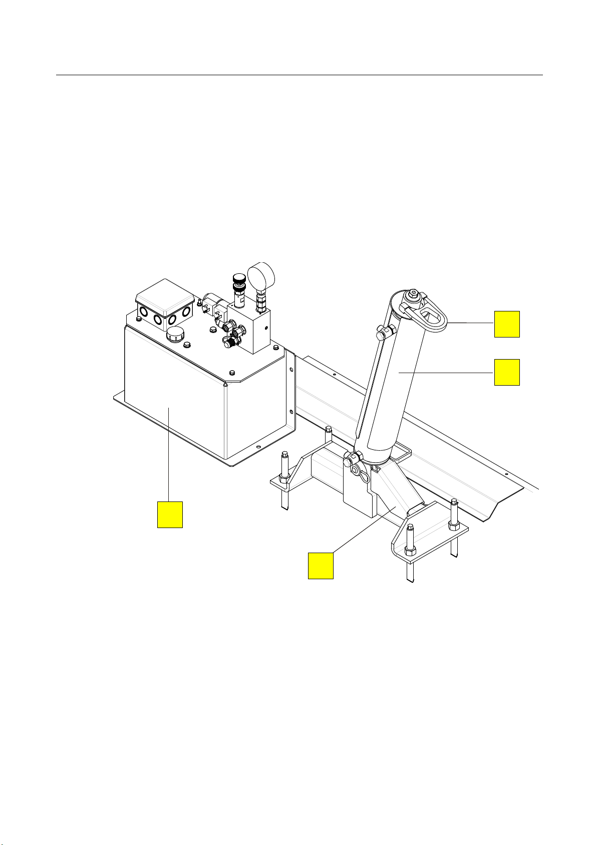
Hydraulic cylinder
(foldable for MLS 1100 and 2100)
Lock
Pos: 27 /Technische Dokumentation/Bremsprüftechnik/MBT-SERIES/042501 MLS/BA/Inhalt: 0425 Aufbau MLS (Bild) @ 34\mod_1382607313523_0. docx @ 1845264 @ @ 1
(Example)
Eyelet for chain slings
Hydraulic power unit
B
A
D
Pos: 28 /Technische Dokumentation/Alle Geräte/Überschriften/Überschriften 1.1.1/R/Überschrift 1.1.1: Rollensatzanhebung @ 38\mod_1403791920051_75.docx @ 2045362 @ 3 @ 1
Pos: 29 /Technische Dokumentation/Bremsprüftechnik/MBT-SERIES/042501 MLS/BA/Inhalt: 0425 Aufbau RSA @ 34\mod_1382627336243_75.doc x @ 1845899 @ @ 1
• Hydraulic power unit and gear flow divider
The power unit is attached in a foundation recess, and connected to the hydraulic
cylinder via eight tubes.
• Built-in tub and cylinder
The eight cylinders of the two roller sets are synchronised with each other, i.e. the
Pos: 30 /-----Format-----/MANUELLER UMBRUCH Seitenumbruch @ 0\mod_11344035 77687_0.docx @ 1277 @ @ 1
roller sets move up and down at the same level, and are secured with stop valves.
C
BA042501-en
Page 8

8
2.3
Specifications
2.3.1
Weight Simulator
2.3.2
Roller Set Lift
MBT 2000
RS5
MBT 4000/7000
RS2/W
MBT 4000/7000
RS2 integrated
Pos: 31 /Technische Dokumentation/Alle Geräte/Überschriften/Überschriften 1.1/T/Überschrift 1.1: Technische Daten @ 7\mod_1184075526343_75.docx @ 99711 @ 3 @ 1
Pos: 32 /Technische Dokumentation/Alle Geräte/Überschriften/Überschriften 1.1.1/G/Überschrift 1.1.1: Gewichtssimulator @ 38\mod_1403791709436_75.docx @ 2045316 @ 3 @ 1
Pos: 33 /Technische Dokumentation/Bremsprüftechnik/MBT-SERIES/042501 MLS/BA/Inhalt: 0425 Technische Daten (Tabelle) MLS @ 29\mod_ 1340704571729_75.doc x @ 1613227 @ @ 1
MLS 1100 MLS 2100 MLS 2150 MLS 2200 MLS 2300
Qty. HD cylinders 1 2 2 2 2
Working stroke per HD cylinder
Hydraulic oil fill volume (initial
filling)
400 mm
400 mm 144 mm 400 mm 400 mm
10 l 12 l 12 l 12 l 42 l
Max. weight simulation 5000 kg 10.000 kg (2 x 5000 kg)
Fuse (time-lag) 16 A
Power supply 3 x 400 V + N + P; 50/60 Hz
Working temperature range 5 to 40 °C
Noise emission < 70 dB(A)
Pos: 34 /Technische Dokumentation/Alle Geräte/Überschriften/Überschriften 1.1.1/R/Überschrift 1.1.1: Rollensatzanhebung @ 38\mod_1403791920051_75.docx @ 2045362 @ 3 @ 1
Pos: 35 /Technische Dokumentation/Bremsprüftechnik/MBT-SERIES/042501 MLS/BA/Inhalt: 0425 Technische Daten (Tabelle) RSA @ 54\mod_ 1533017273639_75. docx @ 305359 8 @ @ 1
Maximum capacity (axle load) 2500 kg 10 000 kg 5000 kg
Lifting height 100 mm 250 mm 180 mm
Hydraulic oil fill volume 8 l 60 l 2 x 8 l
Working pressure 65 bar 200 bar ca. 130/140 bar
Supply voltage 3 x 400 V + N + PE; 50 Hz
Pos: 36 /-----Format-----/MANUELLER UMBRUCH Seitenumbruch @ 0\mod_11344035 77687_0.docx @ 1277 @ @ 1
BA042501-en
Page 9
9
3
Operation
3.1
Control via Desk/Power Unit (Weight Simulator only)
↓
↓
Pos: 37 /Technische Dokumentation/Alle Geräte/Überschriften/Überschriften 1/B/Überschrift 1: Bedienung @ 6\mod_1174482271218_75.docx @ 76877 @ 3 @ 1
Pos: 38 /Technische Dokumentation/Alle Geräte/Überschriften/Überschriften 1.1/B/Überschrift 1.1: Bedienung über Pult/Aggregat (nur Gewichtssimulator) @ 34\mod_1382624945890_75.docx @ 1845811 @ 2 @ 1
Pos: 39 /Technische Dokumentation/Bremsprüftechnik/MBT-SERIES/042501 MLS/BA/Inhalt: 0425 Bedienung über Pult/Aggregat (nur Gewichtssimulator) Teil 1 @ 25\mod_1313573450415_75.docx @ 1030979 @ @ 1
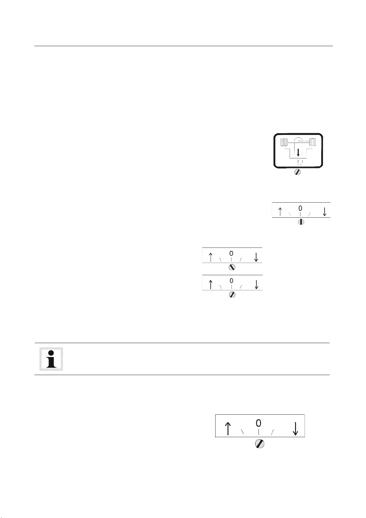
1 After switching on the brake tester, drive into the roller set with the selected
axle.
2 Set the switch with the “pull down” symbol on the brake
testers to position 1.
This sets the roller of the brake testers to ‘inactive’, and they can no longer startup or, if they have already started up, they will switch off.
3 Now switch on the pull-down mechanism at the main
switch (if available). When doing so, the switch for the direction of travel (if available) should be set to position 0.
4 Bring the hydraulic cylinders into the upper 1/3.
Switch:
Turn the switch into the
position ↑ (release) or
(tighten).
Then bring the
switch back into
position 0.
5 Hooking in the straps
There is an eyelet at the hydraulic cylinder that the tightening straps are pulled
through. Then place the straps around the vehicle axle and lash them moderately
tight by moving the handles up and down.
Improper hooking in of the straps may lead to damage of the axle or other parts
hooked in at the same time. This is why the straps must only be hooked in by
trained personnel! Avoid contact with sharp edges!
Once the straps have been hooked in properly and checked for correct fit, the
pull-down process can be started.
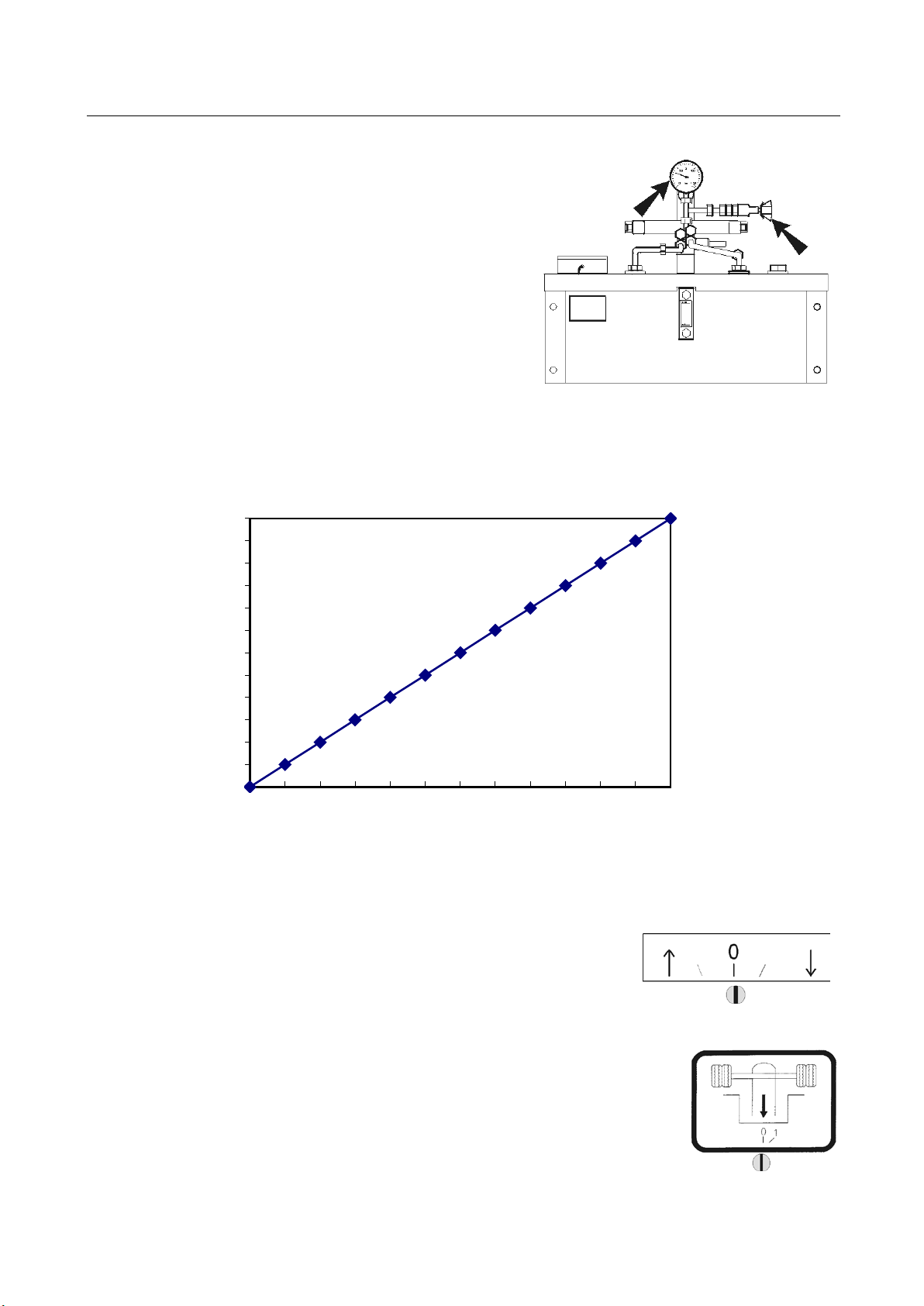
6 Tightening the pull-down mechanism.
Switch:
Turn the switch into position
(tighten)
BA042501-en
Page 10
10
0
1
2
3
4
5
6
7
8
9
10
11
12
0
10
20
30
40
50
60
70
80
90
100
110
120
simuliertes
Gewicht in t
Druck in bar
Set the maximum permissible axle weight at
the manometer with the trick-screw on the
hydraulic pump.
Please note:
1 bar = 100 kg weight. A maximum of 120
bar is possible, i.e. 12.000 kg.
The increase in weight is simultaneously displayed on the brake tester display (if
available).
Pos: 40 /Technische Dokumentation/Bremsprüftechnik/MBT-SERIES/042501 MLS/BA/Inhalt: 0425 Bedienung über Pult/Aggregat (nur Gewichtssimulator) Teil 2 @ 25\mod_1313734513063_75.docx @ 1031683 @ @ 1
BA042501-en
7 Once the desired weight has been reached, perform the following steps:
Switch: Return the switch to position 0.
8 Activate the dynamometer again by returning the “pull
down” switch to position 0. The brake test can now be carried out in accordance with the description in the operating
instructions.
Page 11

11
↑
Once the brake test has been completed, return the switch on
the dynamometer to position 1.
The rollers of the brake testers are now switched off.
To remove the straps, release the pull-down mechanism:
Switch:
Turn the switch to position
(release).
The hydraulic pistons move upwards. Once the tightening
straps hang completely loose, return the switch on the dynamometer to position 0.
The hydraulic pump are now switched off and the straps can
be removed.
Pos: 41 /-----Format-----/MANUELLER UMBRUCH Seitenumbruch @ 0\mod_11344035 77687_0.docx @ 1277 @ @ 1
BA042501-en
Page 12
12
3.2
Control via EUROSYSTEM
3.2.1
Weight Simulator
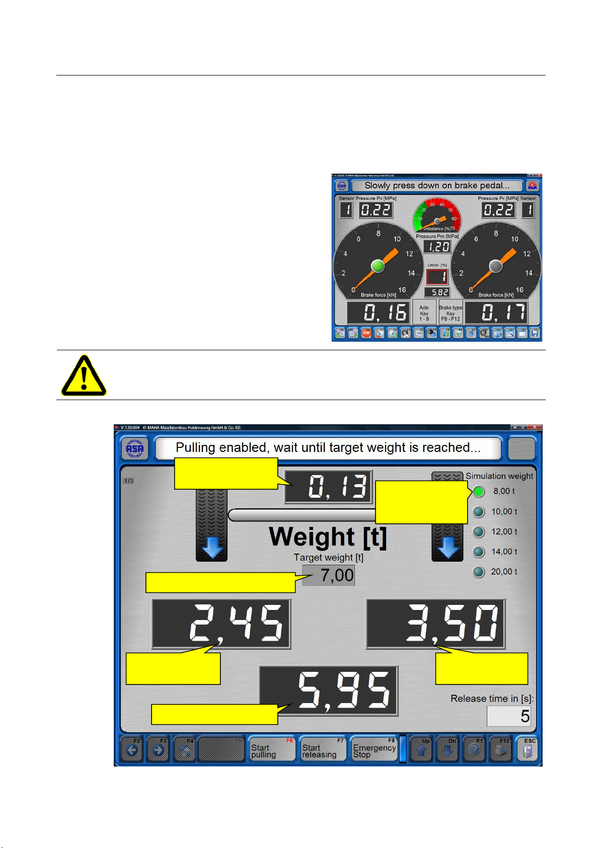
Load currently applied by the MLS
Current weight of
left-side wheel
Current weight of
right-side wheel
Current total axle weight
Target weight entered by user
LED indicating
final load
Pos: 42 /Technische Dokumentation/Alle Geräte/Überschriften/Überschriften 1.1/B/Überschrift 1.1: Bedienung über EUROSYSTEM @ 34\mod_1382624285389_75.docx @ 1845679 @ 2 @ 1
Pos: 43 /Technische Dokumentation/Alle Geräte/Überschriften/Überschriften 1.1.1/G/Überschrift 1.1.1: Gewichtssimulator @ 38\mod_1403791709436_75.docx @ 2045316 @ 3 @ 1
Pos: 44 /Technische Dokumentation/Bremsprüftechnik/MBT-SERIES/E10101 EUROSYSTEM Standard/BA/Inhalt: E 101 Lastsimulation (MLS) @ 26\mod_1326872631372_75. docx @ 1511195 @ @ 1
When the Brake Test screen ap-
pears:
1 Open the Load Simulation screen
using <F6>.
2 Install the chains to the vehicle.
3 Enter the target weight.
The program will not accept any in-
puts greater than the maximum final
load which has been preset with the
key switch on the hydraulic power
unit.
When simulating loads of 12 / 14 / 20 t make sure to keep a minimum distance of
1 m between cylinders!
preset maximum
BA042501-en
Page 13

13
4 Start the load simulation using <F6>.
5 When the target weight is reached, use <Esc> to return to the Brake Test
screen.
6 When prompted, confirm with <Enter>.
7 Conduct the brake test.
8 At completion of the brake test, open
the Load Simulation screen again us-
ing <F6>.
9 Release the chains using <F7>.
The release time is indicated in the
bottom right-hand corner. The value
is adjustable in the variables list.
10 Remove the chains from the vehicle.
If the chains are still tensioned and
cannot be removed, repeat the re-
lease procedure using <F7>.
11 Use <Esc> to return to the Brake
Test screen.
12 When prompted, confirm with <En-
ter>.
The motors switch on automatically.
Pos: 45 /-----Format-----/MANUELLER UMBRUCH Seitenumbruch @ 0\mod_11344035 77687_0.doc x @ 1277 @ @ 1
13 Change axles or exit the brake tester.
BA042501-en
Page 14

14
3.2.2
Roller Set Lift
Pos: 46 /Technische Dokumentation/Alle Geräte/Überschriften/Überschriften 1.1.1/R/Überschrift 1.1.1: Rollensatzanhebung @ 38\mod_1403791920051_75.docx @ 2045362 @ 3 @ 1
Pos: 47 /Technische Dokumentation/Bremsprüftechnik/MBT-SERIES/042501 MLS/BA/Inhalt: 0425 Bedienung über ESYS RSA @ 34\mod_1382625355915_ 75.docx @ 1845855 @ @ 1
• Drive onto the barke tester, the scale
screen is displayed.
• Motors start automatically, the meas-
urement screen is displayed.
• Start the load simulation with the
<F6> button, the load simulation
screen is displayed.
• Motors stop automatically.
• Attach shackles to the vehicle.
• Enter target weight via the keyboard,
confirm with <return>. Maximum
weight: 5.00 t.
If a higher weight is entered, this is
automatically reduced to the maxi-
mum value.
BA042501-en
• Activate control with <F6>.
Page 15

15
• Vehicle is lifted up to the target
weight. A blue dot indicates that the
target weight has been reached.
• Exit screen with <ESC>.
• Start motors with <Return> or
button, the measurement
screen is displayed.
• Perform brake test.
WARNING: Do NOT activate parking brake while roller set is lifted!
The vehicle can be lifted out of the roller set.
BA042501-en
Page 16

16
• If the weight control responds during
the braking operation, this is indicat-
ed through the following symbols:
Arrow up, green: Weight too low
Arrow down, yellow: Weight too high
Blue dot: Weight OK
• Apply brakes if the vehicle slips.
• Save measurement values: Enter axle number, then <Return> or .
• If the minimum brake pressure is not
reached, this message appears. Sel-
ect option.
• After completion of the brake test,
switch to load simulation screen with
the <F6> button.
• Motors stop automatically.
• Press <F5> button. Roller set is low-
ered, and control is deactivated.
• Once the pre-set time has expired,
this query is displayed. Select an-
swer.
BA042501-en
Page 17

17
• Release shackles on the vehicle.
• Leave load simulation screen with
<ESC>.
• Start motors with <Return> or
button, the measurement
screen is displayed.
• Change axle, repeat test steps as
required.
Pos: 48 /-----Format-----/MANUELLER UMBRUCH Seitenumbruch @ 0\mod_11344035 77687_0.docx @ 1277 @ @ 1
BA042501-en
Page 18

18
3.3
Cable Remote (Roller Set Lift only)
A
B
3.4
Remote Control FFB3
3.4.1
Weight Simulator
3.4.2
Roller Set Lift
Pos: 49 /Technische Dokumentation/Alle Geräte/Überschriften/Überschriften 1.1/K/Überschrift 1.1: Kabelfernbedienung (nur Rollensatzanhebung) @ 34\mod_1382624093678_75.docx @ 1845635 @ 3 @ 1
Pos: 50 /Technische Dokumentation/Bremsprüftechnik/MBT-SERIES/042501 MLS/BA/Inhalt: 0425 Kabelfernbedienung (Bild) RSA @ 29\mod_1340619314166_0.docx @ 1612557 @ @ 1
A
B
Pos: 51 /Technische Dokumentation/Bremsprüftechnik/MBT-SERIES/042501 MLS/BA/Inhalt: 0425 Kabelfernbedienung (Text) RSA @ 30\mod_ 1353311467799_75. docx @ 1677252 @ @ 1
Pos: 52 /Technische Dokumentation/Alle Geräte/Überschriften/Überschriften 1.1/F/Überschrift 1.1: Fernbedienung FFB3 @ 34\mod_1382623814914_75.docx @ 1845591 @ 2 @ 1
Pos: 53 /Technische Dokumentation/Alle Geräte/Überschriften/Überschriften 1.1.1/G/Überschrift 1.1.1: Gewichtssimulator @ 38\mod_1403791709436_75.docx @ 2045316 @ 3 @ 1
Pos: 54 /Technische Dokumentation/Bremsprüftechnik/MBT-SERIES/042501 MLS/BA/Inhalt: 0425 Bedienung über FFB3 MLS @ 38\mod_1403864247264_75. docx @ 2047002 @ @ 1
1 Drive onto the brake tester.
2 Pull vehicle down to the desired tar-
get weight by pressing the <Shift>
button, followed by the <Pull down>
button.
3 Perform brake test.
4 Quit weight simulation by pressing the <Shift> button, followed by the
Pos: 55 /Technische Dokumentation/Alle Geräte/Überschriften/Überschriften 1.1.1/R/Überschrift 1.1.1: Rollensatzanhebung @ 38\mod_1403791920051_75.docx @ 2045362 @ 3 @ 1
Pos: 56 /Technische Dokumentation/Bremsprüftechnik/MBT-SERIES/042501 MLS/BA/Inhalt: 0425 Bedienung über FFB3 RSA @ 38\mod_1403863438577_ 75.docx @ 2046266 @ @ 1
<Release> button.
1 Drive onto the brake tester.
Roller set Up
Roller set Down
Shift Release Pull down
2 Raise vehicle to the desired target
weight by pressing the <Shift> but-
ton, followed by the <Raise> button.
3 Perform brake test.
4 Lower vehicle to the desired final position by pressing the <Shift> button,
followed by the <Lower> button.
The height adjustment of the roller set is terminated by releasing the buttons. There is no automatic limit stop.
Pos: 57 /-----Format-----/MANUELLER UMBRUCH Seitenumbruch @ 0\mod_11344035 77687_0.d ocx @ 1277 @ @ 1
BA042501-en
Shift Raise Lower
Page 19

19
3.5
Operation of the stand-alone variant (roller set lift only)
Operation via Remote Control (Model: MRC 1000)
Operation via Control Box
Pos: 58 /Technische Dokumentation/Alle Geräte/Überschriften/Überschriften 1.1/B/Überschrift 1.1: Bedienung der Stand-Alone-Variante (nur Rollensatzanhebung) @ 34\mod_1382621819693_75.docx @ 1845459 @ 2 @ 1
Pos: 59 /Technische Dokumentation/Bremsprüftechnik/MBT-SERIES/042501 MLS/BA/Inhalt: 0425 Bedienung Stand-Alone (Text) RSA @ 30\mod_ 1354881084973_75.d ocx @ 1690251 @ @ 1
A Control LED
B UP
C DOWN
D Manual UP
E Switchover Remote control / Manual
F Manual DOWN
G Main switch with EMERGENCY STOP function
Pos: 60 /Technische Dokumentation/Bremsprüftechnik/MBT-SERIES/042501 MLS/BA/Inhalt: 0425 Bedienung Stand-Alone (Bilder) RSA @ 30\mod_1354881322113_0. docx @ 1690295 @ @ 1
A
B
C
D
E
F
G
Pos: 61 /-----Format-----/MANUELLER UMBRUCH Seitenumbruch @ 0\mod_11344035 77687_0.docx @ 1277 @ @ 1
BA042501-en
Page 20

20
Programming the Remote Control
Pos: 62 /Technische Dokumentation/Bremsprüftechnik/MBT-SERIES/042501 MLS/BA/Inhalt: 0425 FB programmieren Stand-Alone (Text) RSA @ 30\mod_1354882388920_75.doc x @ 1690423 @ @ 1
In the event of loss a new remote control can be "taught" to the receiver:
1 Remove cover lid of receiver.
2 Press the <ON> button on the remote control.
3 Press and hold the TA1 button at the receiver for roughly 3 sec until the LED
starts flashing.
4 Briefly press the <UP> button on the remote control within the next 10 sec.
► After the receiver has saved the transmitter code, the LED flashes quickly for
roughly 2 sec.
5 Repeat steps 2 through 4 for the DOWN function. To do this, press the
Pos: 63 /Technische Dokumentation/Bremsprüftechnik/MBT-SERIES/042501 MLS/BA/Inhalt: 0425 FB programmieren Stand-Alone (Bild) RSA @ 30\mod_ 1354882333759_0. docx @ 1690379 @ @ 1
<DOWN> button on the remote control and the TA2 button on the receiver.
Pos: 64 /-----Format-----/MANUELLER UMBRUCH Seitenumbruch @ 0\mod_1134403577687_0.d ocx @ 1277 @ @ 1
BA042501-en
Page 21

21
3.6
Emergency Lowering
3.6.1
Weight Simulator
Unable to Release Load Simulator?
3.6.2
Roller Set Lift
Emergency Lowering System for Truck Brake Testers
Pos: 65 /Technische Dokumentation/Alle Geräte/Überschriften/Überschriften 1.1/N/Überschrift 1.1: Not-Ab @ 6\mod_1177513569000_75.docx @ 90433 @ 2 @ 1
Pos: 66 /Technische Dokumentation/Alle Geräte/Überschriften/Überschriften 1.1.1/G/Überschrift 1.1.1: Gewichtssimulator @ 38\mod_1403791709436_75.docx @ 2045316 @ 3 @ 1
Pos: 67 /Technische Dokumentation/Bremsprüftechnik/MBT-SERIES/E10101 EUROSYSTEM Standard/BA/Inhalt: E101 Lastsimulator lässt sich nicht lösen? @ 44\mod_1461838446822_75.docx @ 2438162 @ @ 1
1 Switch to 2nd level using < Dn>.
2 <Miscell.>.
Pos: 68 /Technische Dokumentation/Alle Geräte/Überschriften/Überschriften 1.1.1/R/Überschrift 1.1.1: Rollensatzanhebung @ 38\mod_1403791920051_75.docx @ 2045362 @ 3 @ 1
Pos: 69 /Technische Dokumentation/Bremsprüftechnik/MBT-SERIES/042501 MLS/BA/Inhalt: 0425 Notab für Lkw-BPS (Text) @ 38\mod_1403857111244_ 75.docx @ 2046080 @ @ 1
1 Set main switch to OFF.
2 Remove clamps from cables.
3 Open switch cabinet, remove F10 fuse.
4 Place the 24 V DC from the battery onto the clamps of the “DOWN” valves. See
circuit diagram for details. CAUTION: Risk of polarity reversal!
5 Connect cable to battery with alligator clips (a) or plug into the cigarette lighter
(b).
Pos: 70 /-----Format-----/MANUELLER UMBRUCH Seitenumbruch @ 0\mod_11344035 77687_0.doc x @ 1277 @ @ 1
Once the power supply is switched on, the roller set is automatically lowered.
3 <Release load simulator (MLS)>.
BA042501-en
Page 22

22
1
2
Pos: 71 /Technische Dokumentation/Bremsprüftechnik/MBT-SERIES/042501 MLS/BA/Inhalt: 0425 Notab für Lkw-BPS (Bilder) @ 38\mod_1403855357832_0. docx @ 2046034 @ @ 1
BA042501-en
Page 23

23
4 3 5a
5b
Pos: 72 /-----Format-----/MANUELLER UMBRUCH Seitenumbruch @ 0\mod_11344035 77687_0.docx @ 1277 @ @ 1
BA042501-en
Page 24

24
3.7
Pneumatic Emergency Lowering for MBT 4000/7000 with Integrated Roller Set Lift
3.7.1
Function
B C F E D
A
Pos: 73 /Technische Dokumentation/Alle Geräte/Überschriften/Überschriften 1.1/P/Überschrift 1.1: Pneum. Not-Ab-Einrichtung für MBT 4000/7000 mit integrierter Rollensatzanhebung @ 48\mod_1486725175400_75.docx @ 2836272 @ 2 @ 1
Pos: 74 /Technische Dokumentation/Alle Geräte/Überschriften/Überschriften 1.1.1/F/Überschrift 1.1.1: Funktion @ 48\mod_1486724916975_75.docx @ 2836224 @ 3 @ 1
Pos: 75 /Technische Dokumentation/Bremsprüftechnik/MBT-SERIES/042501 MLS/BA/Inhalt: 0425 Pneum. Notab RSA - Funktion (Text) @ 48\mod_1486723389941_75.docx @ 2836175 @ @ 1
A pneumatic manual override with compressed air connection (A) is mounted on
the hydraulic power units of the roller set halves on the right (B) and left (C).
A pneumatic hose (D) in the cable conduit connects the roller set halves, and
leads to the control desk (E) or another suitable location outside the hazard area.
Here, the brake tester can be lowered with the emergency lowering control unit
Pos: 76 /Technische Dokumentation/Bremsprüftechnik/MBT-SERIES/042501 MLS/BA/Inhalt: 0425 Pneum. Notab RSA - Funktion (Bilder) @ 48\mod_1486721253179_0.docx @ 2836128 @ @ 1
(F).
Pos: 77 /-----Format-----/MANUELLER UMBRUCH Seitenumbruch @ 0\mod_11344035 77687_0.docx @ 1277 @ @ 1
BA042501-en
Page 25

25
3.7.2
Operation
A
E
B
F
C
G
D
H
F G H
D
Pos: 78 /Technische Dokumentation/Alle Geräte/Überschriften/Überschriften 1.1.1/B/Überschrift 1.1.1: Bedienung @ 21\mod_1284362724684_75.docx @ 890073 @ 3 @ 1
Pos: 79 /Technische Dokumentation/Bremsprüftechnik/MBT-SERIES/042501 MLS/BA/Inhalt: 0425 Pneum. Notab RSA - Bedienung (Text) @ 48\mod_1486726690737_75.docx @ 2836367 @ @ 1
1 Remove extension piece (G) from the handle of the emergency lowering control
unit (F) and screw on.
2 Screw extension piece onto the test connection (H).
3 Engage emergency lowering control unit. The brake tester is lowered.
4 Once lowered completely, remove the extension piece from the test connection
and stow in the emergency lowering control unit. Store safely, e.g. in the
control desk.
Once the emergency lowering control unit has been removed, there is no pressure
in the system.
(Example)
Pneum. manual override
Roller set half, right
Roller set half, left
Pneumatic hose
Pos: 80 /Technische Dokumentation/Bremsprüftechnik/MBT-SERIES/042501 MLS/BA/Inhalt: 0425 Pneum. Notab RSA - Bedienung (Bild) @ 48\mod_1486726312013_0.docx @ 2836320 @ @ 1
Pos: 81 /-----Format-----/MANUELLER UMBRUCH Seitenumbruch @ 0\mod_11344035 77687_0.docx @ 1277 @ @ 1
Control desk
Emergency lowering control unit (air
pump)
Extension piece
Test connection
BA042501-en
Page 26
26
4
Maintenance
4.1
Annual Inspection
12 (twelve) months
4.2
Maintenance by the Operator
Pos: 82 /Technische Dokumentation/Alle Geräte/Überschriften/Überschriften 1/I/Überschrift 1: Instandhaltung @ 28\mod_1332159812536_75.docx @ 1565908 @ 2 @ 1
Pos: 83 /Technische Dokumentation/Alle Geräte/Inhalte/Sicherheit/Inhalt: Hauptschalter aus bei Instandhaltung_12pt (2018-08-22 10:06:49) @ 26\mod_1324465229892_75.docx @ 1140563 @ @ 1
Danger! Electric shock hazard!
Before doing any maintenance work, turn off the main switch and protect it
against tampering.
Pos: 84 /Technische Dokumentation/Alle Geräte/Überschriften/Überschriften 1.1/J/Überschrift 1.1: Jährliche Überprüfung @ 28\mod_1332230089694_75.docx @ 1566204 @ 2 @ 1
Pos: 85 /Technische Dokumentation/Alle Geräte/Inhalte/Info!/Inhalt: Info - Jährliche Überprüfung_12pt @ 25\mod_1324460481075_75.docx @ 1139412 @ @ 1
• The maintenance interval prescribed by the manufacturer is
This maintenance interval refers to normal workshop usage. If the equipment is
used more frequently or under severe operating conditions (e.g. outdoors), the
interval must be reduced accordingly.
• Maintenance work shall be done only by authorized and trained service techni-
cians provided by the manufacturer, licensed dealers or service partners.
• In case of non-compliance the manufacturer's warranty becomes void.
Pos: 86 /Technische Dokumentation/Alle Geräte/Überschriften/Überschriften 1.1/I/Überschrift 1.1: Instandhaltung durch den Betreiber @ 28\mod_1332231100716_75.docx @ 1566248 @ 2 @ 1
.
Pos: 87 /Technische Dokumentation/Bremsprüftechnik/MBT-SERIES/042501 MLS/BA/Inhalt: 0425 Instandhaltung durch den Betreiber Allg @ 29\mod_1340621873964_75.docx @ 1612865 @ @ 1
The filters in the hydraulic system must be checked for contamination periodically
(suction, return flow, and pressure filters). Please take note of the contamination
indicators mounted to the filters (mechanical, optical and electrical). The filter
element must be changed immediately when the contamination indicator displays
contamination. The original elements listed in the spare and wear parts list must
be used.
The fluid level in the container must be checked daily in order to ensure that it
does not fall below the minimum level.
Check the pipe systems for leaks periodically. Leaking screw connections must be
tightened in unpressurised state.
We recommend keeping maintenance logs in order to record the intervals for filter
changes, gas pressure and storage control checks.
As hydraulic systems can be very different, these instructions should only be
Pos: 88 /-----Format-----/MANUELLER UMBRUCH Seitenumbruch @ 0\mod_1134403577687_0.d ocx @ 1277 @ @ 1
considered as general guidelines.
BA042501-en
Page 27

27
4.3
Refilling with Hydraulic Fluid
4.4
Spare Parts
Pos: 89 /Technische Dokumentation/Alle Geräte/Überschriften/Überschriften 1.1/H/Überschrift 1.1: Hydrauliköl nachfüllen @ 6\mod_1180614998015_75.docx @ 94590 @ 2 @ 1
Pos: 90 /Technische Dokumentation/Bremsprüftechnik/MBT-SERIES/042501 MLS/BA/Inhalt: 0425 Hydrauliköl nachfüllen @ 29\mod_1340621491863_75.docx @ 1612821 @ @ 1
A hydraulic fluid as specified in our table of recommended fluids must be used. To
ensure optimum function, the viscosity of the hydraulic fluid used may not be
greater than 600 mm2/s (cSt) and not less than 12 mm2/s (cSt). When refilling,
make sure to use the same type of hydraulic fluid. Otherwise, the existing fluid
quantity must be completely removed and the entire system rinsed thoroughly.
Please ensure that only pure fluid is filled into the tank. Fill the fluid to the upper oil
level indicator.
To ensure a long service life of the hydraulic components, the fluid must be
checked for the level of contamination or replaced; this must be done periodically,
Pos: 91 /Technische Dokumentation/Alle Geräte/Überschriften/Überschriften 1.1/E/Überschrift 1.1: Ersatzteile @ 18\mod_1255596847002_75.docx @ 474414 @ 2 @ 1
Pos: 92 /Technische Dokumentation/Alle Geräte/Inhalte/Inhalt: Ersatzteile - Alle Geräte_12pt @ 26\mod_1324468768120_75.docx @ 1141219 @ @ 1
but at least every 12 months.
To ensure safe and reliable operation, only use original spare parts supplied by the
Pos: 93 /-----Format-----/MANUELLER UMBRUCH Seitenumbruch @ 0\mod_1134403577687_0.docx @ 1277 @ @ 1
equipment manufacturer.
BA042501-en
Page 28

28
4.5
Checking and Refilling the Bladder Accumulator
Checking the Accumulator Pressure
Refilling with Gas
Removing the Filling Valve
Pos: 94 /Technische Dokumentation/Alle Geräte/Überschriften/Überschriften 1.1/B/Überschrift 1.1: Blasenspeicher überprüfen und befüllen @ 34\mod_1382623170483_75.docx @ 1845547 @ 2 @ 1
Pos: 95 /Technische Dokumentation/Bremsprüftechnik/MBT-SERIES/042501 MLS/BA/Inhalt: 0425 Blasenspeicher überprüfen/befüllen (Text) @ 33\mod_1372754633034_75.docx @ 1802757 @ @ 1
1 Unscrew the black plastic cap and nut from the bladder accumulator.
2 Before screwing onto the bladder accumulator, open the adapter piece
completely (anticlockwise) until you can hear a slight "clicking" noise. Tool: Allen
key A/F 6 mm.
3 Screw the adapter piece with knurled nut completely onto the bladder
accumulator.
4 Screw filling valve (A) including pressure gauge (B) with knurled nut onto the
adapter piece. In doing so, make sure that the drain valve (C) is closed.
5 Open the filling valve by tightening the cam wheel (D) until the pressure gauge
displays the filling pressure. If the filling quantity is too much, the pressure can
be reduced via the drain valve.
6 Screw one end of the high-pressure hose with connection 1/4" on the filling
valve and the other end on the nitrogen cylinder. Slightly tighten the nut using
an open ended wrench.
7 Now the correct amount of gas can be added by opening the valve of the
nitrogen cylinder (E).
8 Once the pressure has been reached and has stabilized, close the valve of the
nitrogen cylinder. If the filling quantity is too much, the pressure can be reduced
via the drain valve.
9 Undo the cam wheel on the filling valve anticlockwise until you can hear a slight
"clicking" noise.
10 Carefully remove the high-pressure hose.
11 Slowly and carefully open the drain valve to allow the remaining nitrogen to be
dispersed.
12 First remove the drain valve and then the adapter piece from the bladder
accumulator.
13 Important: Observe the tightness of the valve on the bladder accumulator in all
Pos: 96 /-----Format-----/MANUELLER UMBRUCH Seitenumbruch @ 0\mod_1134403577687_0.docx @ 1277 @ @ 1
cases!
BA042501-en
Page 29

29
1 2 3 6 4 / 5
7
Pos: 97 /Technische Dokumentation/Bremsprüftechnik/MBT-SERIES/042501 MLS/BA/Inhalt: 0425 Blasenspeicher überprüfen/befüllen (Bilder) @ 33\mod_1372755289930_0.docx @ 1802802 @ @ 1
B
D
Pos: 98 /-----Format-----/MANUELLER UMBRUCH Seitenumbruch @ 0\mod_1134403577687_0.docx @ 1277 @ @ 1
A
C
E
BA042501-en
Page 30

30
5
Dismantling
6
Disposal
7
Contents of the Declaration of Conformity
MAHA Maschinenbau Haldenwang GmbH & Co. KG
Model:
Designation:
Directives:
Standards:
Bezeichnung:
Directives:
Standards:
Pos: 99 /Technische Dokumentation/Alle Geräte/Überschriften/Überschriften 1/D/Überschrift 1: Demontage @ 19\mod_1266336822863_75.docx @ 742452 @ 3 @ 1
Pos: 100 /Technische Dokumentation/Alle Geräte/Inhalte/Inhalt: Demontage - Alle Geräte_12pt @ 26\mod_1324466078229_75.docx @ 1140857 @ @ 1
Decommissioning and dismantling of the equipment may be done only by
specially authorized and trained personnel provided by the manufacturer, licensed
Pos: 101 /Technische Dokumentation/Alle Geräte/Überschriften/Überschriften 1/G/Überschrift 1: Geräteentsorgung @ 6\mod_1174482271625_75.docx @ 76901 @ 3 @ 1
Pos: 102 /Technische Dokumentation/Alle Geräte/Inhalte/Inhalt: Geräteentsorgung durch Betreiber allg_12pt @ 26\mod_1324467874153_75.docx @ 1140955 @ @ 1
dealers or service partners.
Pay attention to the product and safety data sheets of the lubricant used. Avoid
damage to the environment. Should a disposal of the device be necessary it must
be done in adherence with locally applicable legal regulations regarding
environmental protection. Remove all materials properly sorted out and bring them
to a suitable waste disposal service. Collect operating materials such as grease,
oils, coolant, solvent-based cleaning fluids etc. in suitable containers and dispose
Pos: 103 /Technische Dokumentation/Alle Geräte/Inhalte/Inhalt: Geräteentsorgung über Fachbetrieb (alternativ)_12pt @ 26\mod_1324468120852_75.docx @ 1141022 @ @ 1
of in an environmentally protective manner.
Alternatively, you may take the equipment to a specialised waste management
plant to ensure that all components and operating liquids are properly disposed
Pos: 104 /Technische Dokumentation/Alle Geräte/Überschriften/Überschriften 1/I/Überschrift 1: Inhalt der Konformitätserklärung @ 22\mod_1292856748432_75.docx @ 958616 @ 2 @ 1
of.
Pos: 105 /Technische Dokumentation/Alle Geräte/Inhalte/Inhalt: Inhalt der Konformitätserklärung allg_12pt @ 26\mod_1324468436145_75.docx @ 1141120 @ @ 1
herewith declares as a manufacturer its sole responsibility to ensure that the
product named hereafter meets the safety and health regulations both in design
and construction required by the EC directives stated below.
This declaration becomes void if any change is made to the product that was not
Pos: 106 /Technische Dokumentation/Bremsprüftechnik/MBT-SERIES/042501 MLS/BA/Inhalt: 0425 Inhalt der Konformitätserklärun g MLS @ 38\mod_1403865261303_ 75.docx @ 2047048 @ @ 1
discussed and approved by named company beforehand.
Pos: 107 /Technische Dokumentation/Bremsprüftechnik/MBT-SERIES/042501 MLS/BA/Inhalt: 0425 Inhalt der Konformitätserklärun g RSA @ 30\mod_1357649271983_ 75.docx @ 1699853 @ @ 1
=== Ende der Liste für Textmarke Inhalt ===
MSL 1100 / 2100 / 2150 / 2200 / 2300
Pull-Down Device for Load Simulation
2006/42/EC; 2004/108/EC
DIN EN ISO 12100:2010; DIN EN ISO 13850;
DIN EN ISO 13857; DIN EN 349; DIN EN 60204-1
DIN EN 61000-6-3; DIN EN 61000-6-2
Elevating Roller Set for Load Simulation
2006/42/EC; 2004/108/EC
DIN EN ISO 12100:2010; DIN EN ISO 13850;
DIN EN ISO 13857; DIN EN 349; DIN EN 60204-1
DIN EN 61000-6-3; DIN EN 61000-6-2
BA042501-en
 Loading...