

Page 1

Fehler! Verwenden Sie die Registerkarte 'Start', um Name dem Text zuzuweisen, der hier angezeigt werden soll.Fehler! Verwenden Sie
die Registerkarte 'Start', um Name dem Text zuzuweisen, der hier angezeigt werden soll.Fehler! Verwenden Sie die Registerkarte
'Start', um Name dem Text zuzuweisen, der hier angezeigt werden soll.
MBT 1000 EUROSYSTEM
Roller Brake Tester for Motorcycles and Lightweight Vehicles
Original Operating Instructions
BAE12901-en
Pos: 1 /-----For mat---- -/MAN UEL LER UM BRUC H Seite numbr uch @ 0\mod_ 113 44035 77687_ 0.doc x @ 1277 @ @ 1
Page 2

2
BAE12901-en
Pos: 2 /-----For mat---- -/Inha ltsv er zeic hnis - 3 Ebe nen @ 5\mod_ 116 88674 41046_ 75.do cx @ 729 20 @ @ 1
Contents
1 Safety ...................................................................................................................... 3
1.1 Introduction ......................................................................................................................................... 3
1.2 Symbols .............................................................................................................................................. 3
1.3 Intended Use ....................................................................................................................................... 3
1.4 Inappropriate Use ................................................................................................................................ 3
1.5 Requirements on Operating and Service Personnel ............................................................................. 3
1.6 Safety Instructions for Installation and Initial Operation ........................................................................ 4
1.7 Safety Instructions for Operation ......................................................................................................... 4
1.8 Danger Zone ....................................................................................................................................... 5
1.9 Safety Instructions for Servicing ........................................................................................................... 5
1.10 Safety Features ................................................................................................................................... 6
1.11 Accessories ......................................................................................................................................... 7
1.12 What to Do in the Event of an Accident ............................................................................................... 7
2 Description ............................................................................................................... 8
2.1 General Information ............................................................................................................................. 8
2.2 Overview ............................................................................................................................................. 9
2.3 Specifications .................................................................................................................................... 10
2.4 Noise Emission .................................................................................................................................. 10
3 Transport and Storage ........................................................................................... 11
4 Installation and Initial Operation .............................................................................. 11
5 Operation ............................................................................................................... 11
5.1 Main Switch....................................................................................................................................... 11
5.2 Control Unit ....................................................................................................................................... 12
5.3 Test Procedure .................................................................................................................................. 13
6 Maintenance .......................................................................................................... 14
6.1 Annual Inspection .............................................................................................................................. 14
6.2 Care Instructions ............................................................................................................................... 14
6.3 Spare Parts ....................................................................................................................................... 14
6.4 Chain Drive Maintenance: Cleaning, Retensioning, Lubricating .......................................................... 15
6.5 Greasing the Sensor Roller Hinges .................................................................................................... 17
7 Dismantling ............................................................................................................ 19
8 Disposal ................................................................................................................. 19
9 Contents of the Declaration of Conformity .............................................................. 20
10 Company Information ............................................................................................. 21
Pos: 3 /-----For mat---- -/MAN UELLER UM BRUCH Sei tenumb ruch @ 0\mod _11 34403 5776 87_0.d ocx @ 127 7 @ @ 1
Page 3
3
BAE12901-en
Pos: 4 /Technische D okumen tation/A lle Gerä te/ Überschrif ten/Über schr iften 1/S /Überschr ift 1: Sicherhei t @ 6\mod_1174482399906_75.docx @ 76962 @ 1 @ 1
1
Safety
Pos: 5 /Technisc he D okum entat ion/A lle G erä te/ Übersc hrifte n/Üb ersc hrift en 1 .1/E/ Übers chrif t 1. 1: E inführ ung @ 6\mod_1174482219062_75.docx @ 76793 @ 2 @ 1
1.1
Introduction
Pos: 6 /Technisc he Dokum en tation/ All e Gerä te/In halte /Sic herhe it/In halt : Ei nführ ung Sicher hei t_12p t @ 2 5\mod_1324455248318_75.docx @ 1138886 @ @ 1
Thoroughly read this manual before operating the equipment and comply with the
instructions. Always display the manual in a conspicuous location.
Personal injury and property damage incurred due to non-compliance with these
safety instructions are not covered by the product liability regulations.
Pos: 7 /Technische D okumen tation/A lle Gerä te/ Überschrif ten/Über schr iften 1.1/S/ Übersc hrift 1. 1: Sym bole @ 6\mod_1174482270875_75.docx @ 76865 @ 2 @ 1
1.2
Symbols
Pos: 8 /Technische D okumen tation/A lle Gerä te/In halte/S icherhe it/Inha lt: Symb ole Si cher heit_12p t @ 25\m od_1324456650897_75.docx @ 1139046 @ @ 1
Important safety instructions. Failure to comply with instructions could result in
personal injury or property damage.
Important information.
Pos: 9 /Technische D okumen tation/A lle Gerä te/ Überschrif ten/Über schr iften 1 .1/B/Üb ersc hrift 1.1 : Best immungs gemäßer Geb rauch @ 6\mod _1176 7340 22203_ 75.d ocx @ 88 746 @ 2 @ 1
1.3
Intended Use
Pos: 10 /Techn ische Dokum ent atio n/Brem spr üftec hnik/ MBT-S ERIE S/ E1 2901 MB T 10 00 E URO SYS TEM /BA/ In halt: E1 29 B est imm ungs gem äße r Geb ra uch @ 4 1\mod_1421400610826_75.docx @ 2184918 @ @ 1
This equipment is to be used exclusively for the testing of motorcycles and
lightweight vehicles. Observe the rated axle load.
The equipment shall not be modified without the express written consent of the
manufacturer. In case of non-compliance the declaration of conformity becomes
void.
Pos: 11 /Technische Dokumentat ion/Alle Gerät e/Übersc hriften/Über schriften 1. 1/B/Überschr ift 1.1: Bestimm ungswidr iger Gebrauch @ 18\mod_1255530265027_75.docx @ 471571 @ 2 @ 1
1.4
Inappropriate Use
Pos: 12 /Technische Dokumentat ion/Alle Gerät e/Inhalte/S icherhe it/Inhalt: Bestimm ungswid riger Gebrau ch allg_12pt @ 25\mod_1324455015938_75.docx @ 1138843 @ @ 1
Any use other than described is inappropriate.
Pos: 13 /Technische Dokume ntation/ Alle Ger äte/Üb ersc hriften/ Überschr iften 1.1/A/Üb ersc hrift 1.1: Anf orderun gen a n das Bed ienun gs- und Servic eperson al @ 3 4\mod_1380637497630_75.docx @ 1835413 @ 2 @ 1
1.5
Requirements on Operating and Service Personnel
Pos: 14 /Technische Dokume ntation/ Alle Ger äte/I nhalte/S icher heit/ Inhal t: A nford erun gen a n das Be dienu ngs- und Serv icepers onal_1 2pt (2 016-12-22 08 :48:1 2) @ 34\m od_1 380 637 3483 20_ 75.d ocx @ 183 536 9 @ @ 1
All persons employed in the operation, maintenance, installation, removal and disposal of the device must
• be at least 18 years old,
• be trained and instructed in writing,
• have read and understood this manual
• be on record as having been instructed in safety guidelines.
Pos: 15 /-----For ma t-----/MAN UE LLE R UM BR UCH Se iten umb ru ch @ 0\mod_1134403577687_0.docx @ 1277 @ @ 1
Page 4

4
BAE12901-en
Pos: 16 /Technische Dokume ntation/ Alle Ger äte/Üb ersc hriften/ Überschr iften 1.1/S/Üb ersc hrift 1.1: Sic herheits vorschr iften f ür Ins talla tio n und E rsti nbe triebn ahme @ 24\m od_131 0565 05943 1_75.d ocx @ 102354 3 @ 2 @ 1
1.6
Safety Instructions for Installation and Initial Operation
Pos: 17 /Techn ische Dokum ent atio n/Brem spr üftec hnik/ - Arc hiv -/- Bremsp rüftec hnik A lle -/In halte/ Sic herh eit/ Inhalt : Sic herhe itsv orschr ifte n für die Inbe trieb nahme BP S_12p t @ 26\mod_1326368324234_75.docx @ 1504789 @ @ 1
• The system shall only be commissioned by MAHA service technicians or au-
thorized service partners.
• All parts of the electrical equipment must be protected from moisture and wet-
ness.
• The system shall not be installed and operated in hazardous locations or wash
halls.
• The operator must provide for optional safeguards (e.g. warn lamps, barriers,
etc.) depending on local conditions.
• Wear safety shoes and gloves.
• Safeguard roller set with suitable means (e.g. cordon chains or strap).
• The display must be installed in a secure area and folded into the wall when not
in use (wall hinges optionally available).
• When folding the display, grasp it on the edges. Danger of pinching!
• Ensure that a lockable emergency-stop main switch is installed based on instal-
lation instructions before connecting the feed line. Use motor protection switch
and cable cross sections as per specification. Reference in circuit diagram
(standard delivery), nameplate. Fuse max. X.X A (see nameplate).
• The main switch must be provided by the customer and installed on-site. It
must be positioned in direct vicinity to the tester and takes over the emergencystop function.
Pos: 18 /Technische Dokume ntation/ Alle Ger äte/Üb ersc hriften/ Überschr iften 1.1/S/Üb ersc hrift 1.1: Sic herheits vorschr iften f ür den Betri eb @ 6\mod_1174482268953_75.docx @ 76826 @ 2 @ 1
1.7
Safety Instructions for Operation
Pos: 19 /Techn ische Dokum ent atio n/Brem spr üftec hnik/ - Arc hiv -/- Bremsp rüftec hnik A lle -/In halte/ Sic herh eit/ Inhalt : Sic herhe itsv orschr ifte n für den Betr ieb BPS_1 2pt @ 26\ mod_ 1326700788796_75.docx @ 1505493 @ @ 1
• The system shall only be operated within its performance limits.
• The system shall only be operated by trained personnel.
• The system and surrounding area must be kept clean.
• Switch off the system when not in use and secure the main switch against re-
start with a padlock.
• In emergency situations switch off system with main switch or emergency-stop
switch.
• No persons shall be in the danger zone of the system. Rotating or moving parts
(e.g. test stand rollers) are dangerous.
• Danger of carbon monoxide poisoning with running vehicle engine in closed
rooms. The operator is responsible for providing sufficient air exchange.
• Avoid unnecessary strain on vehicle and tester.
• Drive the vehicle slowly on to the tester.
• Check the danger zone before driving the vehicle onto the tester.
Page 5
5
BAE12901-en
• When the vehicle with the driven axle is on the roller set, exit only with running
roller drive. Exiting with roller drive at standstill can destroy the motors due to
extreme roller acceleration.
• The system shall not be operated without functioning slip monitoring. This can
cause tire damage.
• Never jump start a vehicle with the system. This can lead to equipment dam-
age.
• No 4 wheel-drive vehicles shall be tested on the standard roller set. Damage to
vehicle and system are possible. When in doubt contact your responsible service representative.
• The vehicle must be closed during testing. If persons outside of the vehicle are
endangered, use noise protection.
• The operator shall not leave the vehicle during testing.
• No vehicle shall be parked in/on the roller set or on the optional ramps.
Pos: 20 /Technische Dokume ntation/ Alle Ger äte/Üb ersc hriften/ Überschr iften 1.1/G/ Übersc hrift 1.1: Gefa hrenzo ne @ 1 9\mod _126 69381 22676_ 75.d ocx @ 78 2826 @ 2 @ 1
1.8
Danger Zone
Pos: 21 /Techn ische Dokum ent atio n/Brem spr üftec hnik/ - Arc hiv -/- Bremsp rüftec hnik A lle -/In halte/ Sic herh eit/ Inhalt : Ge fahr enzone - 5m Abstand (Text) BPS_12p t @ 26\mod_1326700917541_75.docx @ 1505537 @ @ 1
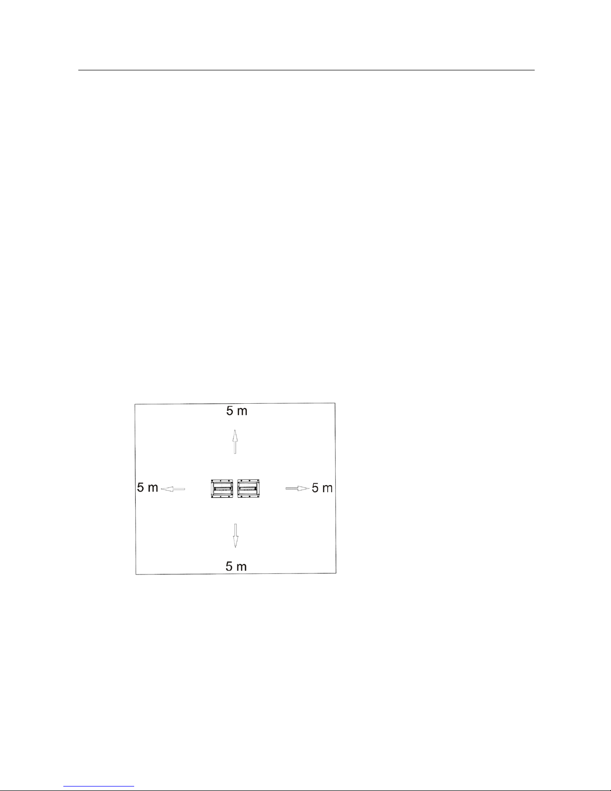
During brake tester operation no persons are allowed in the danger zone:
5 (five) meters
around the roller set in all directions.
Pos: 22 /Techn ische Dokum ent atio n/Brem spr üftec hn ik/- Ar chiv -/- Brem sprüf techn ik Alle -/ Inha lte/S icher hei t/Inha lt: G efa hrenzo ne - 5m Abstand (Bild) BPS @ 19\mod _12 66938 26003 4_0.d ocx @ 784 017 @ @ 1
Pos: 23 /Technische Dokume ntation/ Alle Ger äte/Üb ersc hriften/ Überschr iften 1.1/S/Üb ersc hrift 1.1: Sic herheits vorschr iften f ür Servi cearbeit en @ 6\mod_1174482270640_75.docx @ 76850 @ 2 @ 1
1.9
Safety Instructions for Servicing
Pos: 24 /Techn ische Dokum ent atio n/Brem sprüf tec hnik/- Ar c hiv -/- Br emspr üftechn ik Alle -/ In halte/S iche rhe it/Inha lt: S ic herhe itsvor schri fte n für Servi cearb eite n BPS _1 2pt @ 26\mod_1326700977270_75.docx @ 1505581 @ @ 1
• Service work shall only be done by MAHA service technicians or authorized
service partners.
• Work on electric parts of the system shall only be done by trained electricians.
• The main switch must be switched off and secured against restart before doing
repair, maintenance and set-up work.
• Fire danger due to rubber abrasion on the roller set. Clean regularly. Remove
abrasion before maintenance work.
Page 6

6
BAE12901-en
• The main switch must be secured and if necessary the motor protection switch
turned off when doing work in the roller set.
• When working on the control cabinet or on the roller sets pay attention to the
heating (optional) or hot parts.
• Immediately turn off the tester when it starts up unintentionally. Contact the ser-
vice department.
Pos: 25 /Technische Dokumentat ion/Alle Gerät e/Übersc hriften/Über schriften 1. 1/S/Übersc hrift 1.1: Sicherhe itseinr ichtun gen @ 6\mod_ 1174 4833 24765_ 75.do cx @ 7710 3 @ 2 @ 1
1.10
Safety Features
Pos: 26 /Techn ische Dokum ent atio n/Brem spr üftec hnik/ - Arc hiv -/- Bremsp rüftec hnik A lle -/In halte/ Sic herh eit/ Inhalt : Sic herhe its einric htun gen ( Text) BPS _12pt @ 2 6\mod_1326701513692_75.docx @ 15056 25 @ @ 1
The safety features (partly optional) are to be inspected regularly by an authorized
service technician. Official guidelines must be followed at all times.
The equipment
shall not be operated when the safety features are defective!
•
Lockable Main Switch
Serves as normal On and Off switch for the equipment and as emergency switch.
The switch can be padlocked to protect it against unauthorized usage.
•
Emergency Switch
Is used for quick switch-off during operation. Interrupts the power supply to the
equipment.
•
Startup Monitoring
Prevents the rollers from starting up in case the wheels are blocked (seized
bearings, jammed brake pads). This feature helps prevent the vehicle tyres from
being damaged.
•
Sensor Rollers
The RPM difference between equipment rollers and sensor rollers determines the
slip. Both sensor rollers must be pushed down in order to start the roller brake
tester.
•
Visual and Audible Warning Devices
These must be positioned at a suitable location and must be easily seen or heard
at all times. In the event that the warning devices are defective, the brake tester
must be shut down until they are fully functional again.
•
Pit Safety
Light barrier or infrared movement sensor. If any person enters the safety area, the
brake tester is switched off.
•
Yellow-Black Marking Tape
The yellow-black marking tape around roller set and pit serves to mark out the
brake tester and nust be replaced if defective. Part # 19 6014 (Ø 38 mm) /
19 6015 (Ø 50 mm).
•
Warning and Information Labels
Warning and information labels are attached to the equipment. These must not be
changed or removed and must be replaced if unreadable (see below for part
numbers).
Pos: 27 /Techn ische Dokum ent atio n/Brem spr üftec hnik/ - Arc hiv -/- Bremsp rüftec hnik A lle -/In halte/ Sicher heit/I nhalt: Sic herheits einric htunge n/Aufkleb er (Bild er) BPS @ 23\m od_12 97085 0825 34_0.d ocx @ 9 71558 @ @ 1
Page 7

7
BAE12901-en
54 2132 54 2683
Pos: 28 /Technische Dokume ntation/ Alle Ger äte/Üb ersc hriften/ Über schri ften 1. 1/Z/Üb erschr ift 1. 1: Zube hör @ 7\mod _11 97021 5365 41_75.d ocx @ 13 6790 @ 2 @ 1
1.11
Accessories
Pos: 29 /Technische Dokume ntation/ Alle Ger äte/I nhalte/S icher heit/In halt: Z ubehör_1 2pt @ 25\mod_1324457135414_75.docx @ 1139114 @ @ 1
The equipment shall be operated only with accessories which have been
approved or permitted by MAHA.
Pos: 30 /Technische Dokume ntation/ Alle Ger äte/Üb ersc hriften/ Überschr iften 1.1/V/ Übersc hrift 1 .1: Verh alten b ei Unfä llen @ 19\m od_12 67177 2453 37_75. docx @ 79 4600 @ 2 @ 1
1.12
What to Do in the Event of an Accident
Pos: 31 /Technische Dokume ntation/ Alle Ger äte/I nhalte/S icher heit/In halt: Ver halten b ei U nfällen_ 12pt @ 34\mod_1381128863435_75.docx @ 1837175 @ @ 1
• The injured person is to be removed from the danger area. Find out where
dressing and bandages are kept. Seek first-aid.
• Provide first-aid (stop bleeding, immobilise injured limbs), report the accident
and seal off the accident site.
• Immediately report any accident to your supervisor. Make sure a record is kept
of every occasion first-aid is provided, e.g. in an accident book.
• Remain calm and answer any questions that may arise.
Pos: 32 /-----For ma t-----/MAN UE LLE R UM BR UCH Se iten umb ru ch @ 0\mod_1134403577687_0.docx @ 1277 @ @ 1
Page 8

8
BAE12901-en
Pos: 33 /Technische Dokume ntation/ Alle Ger äte/Übers chriften/ Überschrifte n 1/B/Übers chrift 1: Beschre ibung @ 6\mod_1174482271453_75.docx @ 76889 @ 1 @ 1
2
Description
Pos: 34 /Technische Dokumentat ion/Alle Gerät e/Übersc hriften/Über schriften 1. 1/A/Übersc hrift 1.1: Allgemei nes @ 6\mod_1182865005781_75.docx @ 97736 @ 2 @ 1
2.1
General Information
Pos: 35 /Techn ische Dokum ent atio n/Brem spr üftec hnik/ MBT-SE RIES/E 10101 EUROSY STEM Standard/ BA/Inhalt: E 101 Beschre ibung Al lgemeines @ 26\mod_1326701721816_75.docx @ 1505669 @ @ 1
The safety test lane EUROSYSTEM uses modular design. It is easily expandable
and has the following function groups as standard equipment: side-slip tester,
shock tester, brake tester. In addition, all kinds of MAHA test equipment can be
connected. Test equipment from other manufacturers can be integrated in some
instances.
PC and screen display as well as EUROSYSTEM software are standard
equipment. This test lane-specific software developed by MAHA is based on the
Windows operating system and is network-compatible. The measurement values
can be processed on your own computer network.
Measurement data can be stored with or without remote control and organized in
databases. An additional analog display (pointer) can be used.
Pos: 36 /-----For ma t-----/MAN UE LLE R UM BR UCH Se iten umb ru ch @ 0\mod_1134403577687_0.docx @ 1277 @ @ 1
Page 9

9
BAE12901-en
Pos: 37 /Technische Dokumentat ion/Alle Gerät e/Übersc hriften/Über schriften 1. 1/Ü/Überschr ift 1.1: Übers icht @ 7\mod_ 11870 87953 953_7 5.doc x @ 10369 8 @ 2 @ 1
2.2
Overview
Pos: 38 /Technische Dokume ntation/ Bremsp rüftec hnik/MBT-SERIE S/E 129 01 M BT 100 0 E UROS YS TEM/ BA/I nha lt: E1 29 Übe rs ich t (Bi lder ) @ 41\m od_1421409403608_0.docx @ 2185242 @ @ 1
Pos: 39 /Techn ische Dokum ent atio n/Brem spr üftec hnik/ MBT-S ERIE S/ E1 2901 MB T 10 00 E URO SYS TEM /BA/ In halt: E1 29 Übers icht ( Legend e) @ 41\mod_1421410491305_75.docx @ 2185288 @ @ 1
Examples:
A
Flush-floor version
B
Surface-mounted version
Illustrations show highest expansion stage with roller sets 1 + 2 and clamping device.
Pos: 40 /-----For ma t-----/MANUELLER UM BRUC H Se ite num br uch @ 0\m od_1134403577687_0.docx @ 1277 @ @ 1
A
B
Page 10

10
BAE12901-en
Pos: 41 /Technische Dokumentat ion/Alle Gerät e/Übersc hriften/Über schriften 1. 1/T/Überschr ift 1.1: Technis che Daten @ 7\mod_1184075526343_75.docx @ 99711 @ 2 @ 1
2.3
Specifications
Pos: 42 /Tec hnische Do kument ation/Br emspr üftechn ik/MBT-SE RIES /E129 01 MBT 1000 E UROSYS TEM/BA/ Inhal t: E129 Technis che Daten ( Tabel le) @ 4 0\mod_1415007623249_75.docx @ 2138985 @ @ 1
RS1 RS2
Fuse 25 A time-delay
Drive power 3 kW
Roller set dimensions
(H x W x L)
280/315* x700 x 1150 mm 280/315* x1400 x 1150 mm
Display range 0 – 3 kN
Testable wheel bases 800 – 1500 mm
Testable wheel diameters 380 – 700 mm
Test speed 5 km/h
Wheel load (drive-over load) 1000 kg
Roller centre distance 380 mm
Roller diameter 202 mm
Roller length 350 mm 1100 mm
Power supply 3 x 400 V/NPE 50 Hz
*315 mm height only in conjunction with dynamometer
Pos: 43 /Technische Dokumentat ion/Alle Gerät e/Übersc hriften/Über schriften 1. 1/L/Überschr ift 1.1: Lärmem ission @ 13\mod_ 12367 67272 078_7 5.doc x @ 35457 9 @ 2 @ 1
2.4
Noise Emission
Pos: 44 /Techn ische Dokum ent atio n/Brem spr üftec hnik/ MBT-SERIES/E10101 EUROSYSTEM Standard/BA/Inhalt: E101 Lärmemission @ 26\mod_1326714188804_75.docx @ 1507042 @ @ 1
The noise emission during a vehicle test results mainly from the vehicle’s engine.
The noise emission varies from vehicle to vehicle and cannot be attributed to the
testing equipment.
Roller Brake Tester
The noise emission value created by the brake tester (roller drive) is less than
70 dB(A) in the work area of the operator.
Shock Tester
The noise emission value created by the shock tester (oscillating test plates) is
between 75 and 80 dB(A) in the work area of the operator.
Side-Slip Tester
The noise emission value created by the side-slip tester is less than 70 dB(A) in
the work area of the operator.
Pos: 45 /-----For ma t-----/MAN UE LLE R UM BR UCH Se iten umb ru ch @ 0\mod_1134403577687_0.docx @ 1277 @ @ 1
Page 11

11
BAE12901-en
Pos: 46 /Technische Dokume ntation/ Alle Ger äte/Üb ersc hriften/ Überschr iften 1/T/ Über schr ift 1: Tra nsp ort und Lage ru ng @ 20\mod_1268732488860_75.docx @ 826153 @ 1 @ 1
3
Transport and Storage
Pos: 47 /Technische Dokumentat ion/Alle Gerät e/Inhalte/I nhalt: Transp ort und Lagerung _12pt @ 26\mod_1324468980166_75.docx @ 1141285 @ @ 1
Check package to ensure it is complete, in accordance with the order
confirmation. Report any transport damage to the carrier immediately.
During loading, unloading and transport always use suitable lifting equipment,
material handling equipment (e.g. cranes, forklifts, etc.) and the right load handling
attachments and slings. Always ensure that the parts to be transported are
suspended or loaded properly so that they cannot fall, taking into account size,
weight and the centre of gravity.
Store the packages in a covered area, protected from direct sunlight, at a low
humidity and with temperatures between 0...+40 °C (32…104 °F). Do not stack
packages.
When unpacking, take care to avoid any possibility of injury or damage. Keep at a
safe distance when opening the package strapping, do not allow any parts to fall
out.
Pos: 48 /Technische Dokume ntation/ Alle Ger äte/Üb ersc hriften/ Überschr iften 1/M/Über schr ift 1: M ontage und Er stinbe triebnahm e @ 18\mod_1255417443299_75.docx @ 463797 @ 1 @ 1
4
Installation and Initial Operation
Pos: 49 /Technische Dokume ntation/ Alle Ger äte/I nhalte/I nhalt: M onta ge und Erstinb etrieb nahme_ 12pt @ 26\mod_1324468562877_75.docx @ 1141153 @ @ 1
Installation and initial operation of the equipment may be done only by authorized
and trained service technicians provided by the manufacturer, licensed dealers or
service partners.
Pos: 50 /Technische Dokumentat ion/Alle Gerät e/Übersc hriften/Über schriften 1/B/ Überschri ft 1: Bedienung @ 6\mod_1174482271218_75.docx @ 76877 @ 1 @ 1
5
Operation
Pos: 51 /Tec hnisch e Dokumentat ion/Alle Gerät e/Übersc hriften/Über schriften 1. 1/H/Überschr ift 1.1: Hauptsch alter @ 6\mod _117 75928 58312_ 75.d ocx @ 90 635 @ 2 @ 1
5.1
Main Switch
Pos: 52 /Technische Dokume ntation/ Alle Ger äte/I nhalte/I nhalt: H aupts chalter v2 - A lle Gerä te_1 2pt @ 30\m od_1351692594628_75.docx @ 1671389 @ @ 1
• Main switch in position 0: Power supply OFF
• Main switch in position 1: Power supply ON
• When in position 0, the main switch can be protected against
tampering by means of a padlock.
Pos: 53 /-----For ma t-----/MAN UE LLE R UM BR UCH Se iten umb ru ch @ 0\mod_1134403577687_0.docx @ 1277 @ @ 1
Page 12

12
BAE12901-en
Pos: 54 /Technische Dokumentat ion/Alle Gerät e/Übersc hriften/Über schriften 1. 1/B/Überschr ift 1.1: Bedienei nheit @ 6\mod_1177424155343_75.docx @ 90114 @ 2 @ 1
5.2
Control Unit
Pos: 55 /Techn ische Dokum ent atio n/Brem spr üftec hnik/ MBT-SERIES/E12901 MBT 1000 EUROSYSTEM/BA/Inhalt: E129 Bedieneinheit (Bilder) @ 41\mod_1421406400641_0.docx @ 2185150 @ @ 1
Pos: 56 /Tec hn isch e Dok ument atio n/Brem sprüf tec hnik/M BT-SER IE S/E 129 01 M BT 100 0 EUR OSY STE M/ BA/I nhal t: E129 Be die neinh ei t (L egend e) @ 4 1\mod_1421407129636_75.docx @ 2185196 @ @ 1
A
Emergency stop button
D
Lifting bar Speedometer tester (opt.)
B
Motors On/Off
E
Clamping device, front (option)
C
Lifting bar Brake tester (left: option)
F
Clamping device, rear (option)
The control unit is continuously movable along the handrail and can be swivelled
sideways after pulling it in a forward direction.
Pos: 57 /-----For ma t-----/MA NUE LLE R UM BR UCH Se iten um bru ch @ 0\mod_1134403577687_0.docx @ 1277 @ @ 1
A
B C D
E F
Page 13

13
BAE12901-en
Pos: 58 /Technische Dokume ntation/ Alle Ger äte/Üb ersc hriften/ Überschr iften 1.1/P/Üb ersc hrift 1.1: Pr üfablauf @ 8\mod_1200574029101_75.docx @ 140824 @ 2 @ 1
5.3
Test Procedure
Pos: 59 /Techn ische Dokum ent atio n/Brem spr üftec hnik/ - Arc hiv -/- Bremsp rüftec hnik A lle -/In halte/ Inf o!/In halt : Inf o - Brem spr üfun g VO R Sch lupfab scha ltun g be ende n @ 41\mod_1421412099129_75.docx @ 2185494 @ @ 1
IMPORTANT NOTICE
The statutory requirements for the verification of braking efficiency do not demand
that the brake test be completed until slippage cutoff occurs.
Automatic slippage cutoff should be generally regarded as a safety feature,
not
as
the cutoff point for brake testing.*
It is adequate to terminate the test at approx. 90% of the maximum braking force.
This method is strongly recommended to help prevent tyre damage!
* Please note the implementing provisions for braking efficiency determination.
Pos: 60 /Tec hnische Do kument ation/Br emspr üftechn ik/MBT-S ERIE S/ E1 2901 MB T 10 00 E URO SYS TEM /BA/ In halt: E1 29 P rüfab la uf ( Tex t) @ 41\mod_1421659346487_75.docx @ 2185650 @ @ 1
1 Enter the roller set with the front wheel/axle (A).
2 Secure the rear wheel/axle with the clamping device (B).
3 Perform the brake test.
4 Open the clamping device at the rear wheel/axle.
5 Enter the roller set with the rear wheel/axle.
6 Secure the front wheel/axle with the clamping device.
7 Perform the brake test.
8 Open the clamping device at the front wheel/axle.
9 Exit the brake tester.
Pos: 61 /Techn ische Dokum ent atio n/Brem spr üftec hnik/ MBT-SERIES/E12901 MBT 1000 EUROSYSTEM/BA/Inhalt: E129 Prüfablauf (Bilder) @ 41\mod_1421660434643_0.docx @ 2185752 @ @ 1
Pos: 62 /Techn ische Dokum ent atio n/Brem spr üftec hnik/ MBT-S ERIE S/ E1 2901 MB T 10 00 E URO SYS TEM /BA/ In halt: Inf o - M BT E UROSY STE M-BA beigef ügt @ 41\m od_1421660105247_75.docx @ 2185696 @ @ 1
For a detailed description of the test lane software please see the operating instructions MBT EUROSYSTEM (document No. BAE10101-en, included).
Pos: 63 /-----For ma t-----/MAN UE LLE R UM BR UCH Se iten umb ru ch @ 0\mod_1134403577687_0.docx @ 1277 @ @ 1
A B
Page 14

14
BAE12901-en
Pos: 64 /Technische Dokume ntation/ Alle Ger äte/Üb ersc hriften/ Überschr ifte n 1/I/Über schrift 1: Instand haltun g @ 28\mod_1 33215 98125 36_ 75.docx @ 1565 908 @ 1 @ 1
6
Maintenance
Pos: 65 /Technische Dokume ntation/ Alle Ger äte/I nhalte/W arnu ng!/Inha lt: War nung - H auptsc halter aus bei Instand haltu ng_12pt @ 26\m od_1324465229892_75.docx @ 1140563 @ @ 1
Danger! Electric shock hazard!
Before doing any maintenance work, turn off the main switch and protect it
against tampering.
Pos: 66 /Technische Dokume ntation/ Alle Ger äte/Üb ersc hriften/ Überschr iften 1.1/J/Üb ersc hrift 1.1 : Jähr liche Überp rüfu ng @ 28\mod_1332230089694_75.docx @ 1566204 @ 2 @ 1
6.1
Annual Inspection
Pos: 67 /Technische Dokume ntation/ Alle Ger äte/I nhalte/I nfo!/I nhalt: I nfo - J ährliche Überpr üfung_1 2pt @ 25\mod_1324460481075_75.docx @ 1139412 @ @ 1
• The maintenance interval prescribed by the manufacturer is
12 (twelve) months
.
This maintenance interval refers to normal workshop usage. If the equipment is
used more frequently or under severe operating conditions (e.g. outdoors), the
interval must be reduced accordingly.
• Maintenance work shall be done only by authorized and trained service techni-
cians provided by the manufacturer, licensed dealers or service partners.
• In case of non-compliance the manufacturer's warranty becomes void.
Pos: 68 /Tec hn isch e Do kume nt atio n/A lle Ger äte /Üb ersc hr ifte n/ Über schr ift en 1.1/ P/Üb er sc hrif t 1. 1: P fle geh inwe ise @ 15\m od_12 4591 22348 54_7 5.docx @ 39578 0 @ 2 @ 1
6.2
Care Instructions
Pos: 69 /Technische Dokumentat ion/Alle Gerät e/Inhalte/I nhalt: Pflegeh inweise - Al le Geräte _12pt @ 26\mod_1324468886116_75.docx @ 1141252 @ @ 1
• Periodically clean the equipment and treat it with a care product.
• Repair damage to the paintwork immediately to prevent corrosion.
• Usage of caustic cleaning agents or high pressure and steam jet cleaners may
lead to equipment damage.
Pos: 70 /Technische Dokume ntation/ Alle Ger äte/I nhalte/I nfo!/I nhalt: I nfo - Pflegehinweise_12pt @ 26\mod_1324461215655_75.docx @ 1139602 @ @ 1
Regular care and maintenance is the key condition for functionality and long life
expectancy of the equipment!
Pos: 71 /Technische Dokume ntation/ Alle Ger äte/Üb ersc hriften/ Überschr iften 1.1/E/ Übersc hrift 1 .1: Ersatz teile @ 18\m od_12 5559 68470 02_7 5.docx @ 47441 4 @ 2 @ 1
6.3
Spare Parts
Pos: 72 /Technische Dokume ntation/ Alle Ger äte/I nhalte/I nhalt: Er satzte ile - Alle Gerät e_12pt @ 2 6\mod_1324468768120_75.docx @ 1141219 @ @ 1
To ensure safe and reliable operation, only use original spare parts supplied by the
equipment manufacturer.
Pos: 73 /-----For ma t-----/MAN UEL LER UM BRUCH Seitenum br uch @ 0\mod_1134403577687_0.docx @ 1277 @ @ 1
Page 15

15
BAE12901-en
Pos: 74 /Technische Dokume ntation/ Alle Ger äte/Üb ersc hriften/ Überschr iften 1.1/I/ Überschr ift 1.1: Ins tandhaltu ng des Kette ntriebs : Re inigen, N achspan nen, S chmier en @ 3 6\mod_1394630342377_75.docx @ 1918730 @ 2 @ 1
6.4
Chain Drive Maintenance: Cleaning, Retensioning, Lubricating
Pos: 75 /Technische Dokume ntation/ Alle Ger äte/I nhalte/I nfo!/I nhalt: I nfo - W art ungs int erv all: M ona tl ich_ 12pt @ 26\mod_1324463913433_75.docx @ 1140268 @ @ 1
Maintenance interval: Monthly
Pos: 76 /Techn ische Dokum ent atio n/Brem spr üftec hnik/ - Arc hiv -/- Bremsp rüftec hnik A lle -/In halte/ Inha lt: 0200 Kett en i nstand halt en E inleit ung_ 12p t @ 33\mod _1 374 065 9366 93_ 75.d ocx @ 1 809 475 @ @ 1
Before doing any maintenance work, turn off the main switch and protect it
against tampering.
Remove the roller set covers from above the chains, reinstall before restarting the
brake tester.
Pos: 77 /Techn ische Dokum ent atio n/Brem spr üftec hnik/ - Arc hiv -/- Bremsp rüftec hnik A lle -/In halte/I nhalt: 0200 Ketten reinigen_1 2pt @ 33\mod_1374064814451_75.docx @ 1809387 @ @ 1
Cleaning the Chains
The chains can normally be cleaned using a cloth or brush, stubborn dirt can be
removed with petroleum solvent or benzine. Do not use pickles or acids! Reapply
a new anticorrosive film immediately after using degreasing agents (see section
"Greasing the Chains").
Pos: 78 /Techn ische Dokum ent atio n/Brem spr üftec hnik/ - Arc hiv -/- Bremsp rüftec hnik A lle -/In halte/I nhalt: 02 00 Ketten nachspa nnen_12p t @ 33\mod_1374065445290_75.docx @ 1809431 @ @ 1
Retensioning the Chains
Check the chain slack: the chain should be movable by hand approx. 5 mm up
and down. If the chain needs retensioning, proceed as follows:
• Open the fastening screws.
• Adjust the chain tension using the tensioning screw.
• Tighten the fastening screws (see table for torque figures).
• Recheck the chain slack.
Pos: 79 /Techn ische Dokum ent atio n/Brem spr üftec hnik/ - Arc hiv -/- Bremsp rüftec hnik A lle -/In halte/ Inha lt: 0200 Kett en na chspa nn en - Anz ugsm om ent e @ 3 4\mod_1378969980518_75.docx @ 1825309 @ @ 1
Brake tester
model
Thread
Strength
Tightening
torque
Position
Required for chain
tensioning?
MBT
1xxx/2xxx/3xxx
M10 8.8 50 Nm Running roller yes
M16 8.8 120 Nm Motor mount yes
MBT 4xxx
M18 8.8 350 Nm Running roller yes
M20 8.8 350 Nm Motor mount only for RS1
MBT 5xxx
M16 8.8 220 Nm Running roller no
M18 8.8 350 Nm Motor mount yes
MBT 6xxx/7xxx
M18 8.8 350 Nm Running roller yes
M20 8.8 350 Nm Motor mount only for RS1 + RS3
MBT 7xxx
M18 8.8 500 Nm
Raised running
roller
yes
M27 8.8 500 Nm Motor mount 3:4 no
Pos: 80 /Techn ische Dokum ent atio n/Brem spr üftec hnik/ - Arc hiv -/- Bremsp rüftec hnik A lle -/In halte/ Inha lt: 0200 Kett en sc hmier en_1 2pt @ 3 3\mod_1374063619890_75.docx @ 1809299 @ @ 1
Page 16

16
BAE12901-en
Lubricating the Chains
The service lifetime of the chains directly depends on correct lubrication. Provided
that the lubricating film is continuously maintained, chain wear can be reduced to
a minimum
Recommended lubricant: LongLub adhesive lubricant (MAHA part # 35 1020)
• Lubricate the chain over its entire length while turning over the rollers by hand.
Important: The lubricant must contact the chain links!
Pos: 81 /Techn ische Dokum ent atio n/Brem spr üftec hnik/ - Arc hiv -/- Bremsp rüftec hnik A lle -/In halte/I nhalt : 0200 Ketten schm ieren (B ild) @ 33\mod_1374060263983_0.docx @ 1809079 @ @ 1
Pos: 82 /-----For ma t-----/MAN UE LLE R UM BR UCH Se iten umb ru ch @ 0\mod_1134403577687_0.docx @ 1277 @ @ 1
Page 17

17
BAE12901-en
Pos: 83 /Techn ische Dokum ent atio n/Brem spr üftec hnik/ - Arc hiv -/- Bremsp rüftec hnik A lle -/In halte/ Inha lt: I nst K ette nsp annu ng (B ilder) IW 10 @ 22\m od_ 128 5658 467 283_ 0.d ocx @ 9 020 83 @ @ 1
Pos: 84 /Techn ische Dokum ent atio n/Brem spr üftec hnik/ - Arc hiv -/- Bremsp rüftec hnik A lle -/In halte/ Inha lt: I nst K ette nsp annu ng (Le ge nde) _12p t @ 35\ mod_1393514825943_75.docx @ 1912343 @ @ 1
A
Chain
B
Fastening screws
C
Tensioning screw
Pos: 85 /Technische Dokume ntation/ Alle Ger äte/Üb ersc hriften/ Überschr iften 1.1/T/ Überschr ift 1. 1: Tastr ollensc harnier e schm ieren @ 36\m od_ 139 46304 6953 1_75.d ocx @ 1 91877 4 @ 2 @ 1
6.5
Greasing the Sensor Roller Hinges
Pos: 86 /Technische Dokume ntation/ Alle Ger äte/I nhalte/I nfo!/I nhalt: I nfo - W artun gsint ervall : 200 h / 12 Mo nate_ 12pt @ 26\ mod_1324463609793_75.docx @ 1140170 @ @ 1
Maintenance interval: 200 hours / 12 months
Pos: 87 /Techn ische Dokum ent atio n/Brem spr üftec hnik/ - Arc hiv -/- Bremsp rüftec hnik A lle -/I nhalte/ Inha lt: Ins t Tastr ollen (Text) IW 2/4/7/ 10_12p t @ 41\mod_1421655991818_75.docx @ 2185604 @ @ 1
B B
C
A
Page 18

18
BAE12901-en
Grease the sensor roller hinges every 200 (two hundred) operating hours or once
annually.
1 Remove the cover plates from the roller set.
2 Treat the greasing points (D) using a spray lubricant. Move the sensor roller up
and down.
3 Reinstall the cover plates to the roller set.
Pos: 88 /Techn ische Dokum ent atio n/Brem spr üftec hnik/ - Arc hiv -/- Bremsp rüftec hnik A lle -/In halte/I nhalt: Ins t Tastrol len (Bild er) IW 10 @ 22\mod_1285659960275_0.docx @ 902343 @ @ 1
Pos: 89 /-----For ma t-----/MAN UE LLE R UM BR UCH Se iten umb ru ch @ 0\mod_1134403577687_0.do cx @ 127 7 @ @ 1
D D
Page 19

19
BAE12901-en
Pos: 90 /Technische Dokumentat ion/Alle Gerät e/Übersc hriften/Über schriften 1/D/ Überschr ift 1: Demontage @ 19\mod_1266336822863_75.docx @ 742452 @ 1 @ 1
7
Dismantling
Pos: 91 /Technische Dokume ntation/ Alle Ger äte/I nhalte/I nhalt: Demontage - Alle Geräte_12pt @ 26\mod_1324466078229_75.docx @ 1140857 @ @ 1
Decommissioning and dismantling of the equipment may be done only by
specially authorized and trained personnel provided by the manufacturer, licensed
dealers or service partners.
Pos: 92 /Technische Dokumentat ion/Alle Gerät e/Übersc hriften/Über schriften 1/G/ Überschr ift 1: Geräteentsor gung @ 6\mod_1174482271625_75.docx @ 76901 @ 1 @ 1
8
Disposal
Pos: 93 /Technische Dokume ntation/ Alle Ger äte/I nhalte/I nhalt: Gerät eentsor gung dur ch B etreiber allg_1 2pt @ 26\mod_1324467874153_75.docx @ 1140955 @ @ 1
Pay attention to the product and safety data sheets of the lubricant used. Avoid
damage to the environment. Should a disposal of the device be necessary it must
be done in adherence with locally applicable legal regulations regarding
environmental protection. Remove all materials properly sorted out and bring them
to a suitable waste disposal service. Collect operating materials such as grease,
oils, coolant, solvent-based cleaning fluids etc. in suitable containers and dispose
of in an environmentally protective manner.
Pos: 94 /Technische Dokumentat ion/Alle Gerät e/Inhalte/I nhalt: Gerät eentsorgung über Fachbetr ieb (alternativ)_ 12pt @ 26\mod _1 324 468 1208 52_ 75.d ocx @ 1 141 022 @ @ 1
Alternatively, you may take the equipment to a specialised waste management
plant to ensure that all components and operating liquids are properly disposed
of.
Pos: 95 /-----For ma t-----/MAN UE LLE R UM BR UCH Se iten umb ru ch @ 0\mod_1134403577687_0.docx @ 1277 @ @ 1
Page 20

20
BAE12901-en
Pos: 96 /Technische Dokume ntation/ Alle Ger äte/Üb ersc hriften/ Überschr iften 1/I/Über schr ift 1: In halt der Konf ormitäts erklär ung @ 2 2\mod_ 12928 56748 432_ 75.do cx @ 958 616 @ 1 @ 1
9
Contents of the Declaration of Conformity
Pos: 97 /Technische Dokume ntation/ Alle Ger äte/I nhalte/I nhalt: I nhal t der K onformi tätserkl ärung a llg_1 2pt @ 26\mod_1324468436145_75.docx @ 1141120 @ @ 1
MAHA Maschinenbau Haldenwang GmbH & Co. KG
herewith declares as a manufacturer its sole responsibility to ensure that the
product named hereafter meets the safety and health regulations both in design
and construction required by the EC directives stated below.
This declaration becomes void if any change is made to the product that was not
discussed and approved by named company beforehand.
Pos: 98 /Techn isch e Dok ument atio n/Bre mspr üftec hn ik/MB T-SERI ES /E1 0101 EU ROSY STE M S tand ar d/BA /In hal t: E 101 In halt d er Kon form itä tser klä run g_12p t @ 44\ mod_1461830999778_75.docx @ 2438054 @ @ 1
Model: MBT 1000 EUROSYSTEM / MBT 2250 EUROSYSTEM
MBT 2450 EUROSYSTEM 4WD / MBT 3250 EUROSYSTEM
MBT 3450 EUROSYSTEM 4WD / MBT 4250 EUROSYSTEM
MBT 4450 EUROSYSTEM 4WD / MBT 5250 EUROSYSTEM
MBT 6250 EUROSYSTEM / MBT 7250 EUROSYSTEM
MBT 7450 EUROSYSTEM 4WD
Designation:
Safety Test Lane, consisting of:
Roller Brake Tester:
MBT 1000 EUROSYSTEM:
(optional) Motorcycle Holding Device
Rated Axle Load 2000 kg
Motor Power 2x3 kW
MBT 2250 EUROSYSTEM / MBT 2450 EUROSYSTEM 4WD
MBT 3250 EUROSYSTEM / MBT 3450 EUROSYSTEM 4WD:
Rated Axle Load 3500 kg (optional 4000, 5000 or 8000 kg)
Motor Power 2x3 kW (4 or 5,5 kW optional)
MBT 4250 EUROSYSTEM / MBT 4450 EUROSYSTEM 4WD
MBT 5250 EUROSYSTEM / MBT 6250 EUROSYSTEM:
Rated Axle Load 13 000 kg (optional 15 000 or 18 000 kg)
Motor Power 2x7,5 kW, 2x9 kW, 2x11 kW, 2x15 kW
MBT 7250 EUROSYSTEM / MBT 7450 EUROSYSTEM 4WD:
Rated Axle Load 18 000 kg (optional 20 000 kg)
Motor Power 2x9 kW, 2x11 kW, 2x16 kW
Side-Slip Tester MINC EURO / MINC II EURO:
Rated Axle Load 3000 / 5000 kg
Shock Tester SA2 EURO oder MSD 3000:
Rated Axle Load 1100 kg (optional 2000 kg) or 2200 kg
Speedometer Tester TPS I / II / III; TPS 25
Directives: 2006/42/EC; 2014/30/EU
Standards: DIN EN ISO 12100:2010; DIN EN ISO 13850,
DIN EN ISO 13857,
DIN EN 349; DIN EN 60204-1; DIN EN 61000-6-3,
DIN EN 61000-6-2
Pos: 99 /-----Form at-----/ MAN UE LLE R UM BR UCH Se iten umb ruc h @ 0\mod_1134403577687_0.docx @ 1277 @ @ 1
Page 21

21
BAE12901-en
Pos: 100 /Technische D okumen tation/ Alle G eräte/ Überschr iften/ Übers chrifte n 1/F/Über schr ift 1: Firmen -Infor mation @ 7\m od_11 87338 6258 28_7 5.docx @ 10404 7 @ 1 @ 1
10
Company Information
Pos: 101 /Technische D okumen tation/ Alle G eräte/In halt e/Inhalt : Firmen -Inf ormat ion M AHA @ 42\ mod_1422267670099_75.docx @ 2188049 @ @ 1
© MAHA Maschinenbau Haldenwang GmbH & Co. KG
Legal notice based on ISO 16016:
The reproduction, distribution and utilization of this document as well as the communication of its
contents to others without explicit authorization is prohibited. Offenders will be held liable for the
payment of damages. All rights reserved in the event of the grant of a patent, utility model or design.
The contents of this edition have been checked with great care. However, errors cannot be fully
excluded. Subject to technical change without notice.
Document
Document No.: BAE12901-en
Approval Date: 2016-06-01
Manufacturer
MAHA Maschinenbau Haldenwang GmbH & Co. KG
Hoyen 20
87490 Haldenwang
Germany
Phone: +49 8374 585 0
Fax: +49 8374 585 590
Fax Parts: +49 8374 585 565
Internet: http://www.maha.de
E-Mail: maha@maha.de
Hotline: +49 180 66242 60 for Brake Testers and Test Lanes
+49 180 66242 80 for Automotive Lifts
+49 180 66242 90 for Dynamometers and Emission Testers
Service
AutomoTec GmbH
Maybachstraße 8
87437 Kempten
Germany
Phone: +49 180 66242 50
Fax: +49 180 66242 55
Internet: http://www.automo-tec.com
E-Mail: service@automo-tec.com
=== Ende der Liste für Textm arke In halt ===
 Loading...