

Page 1

Fehler! Verwenden Sie die Registerkarte 'Start', um Name dem Text zuzuweisen, der hier angezeigt werden soll.Fehler! Verwenden Sie
die Registerkarte 'Start', um Name dem Text zuzuweisen, der hier angezeigt werden soll.Fehler! Verwenden Sie die Registerkarte
'Start', um Name dem Text zuzuweisen, der hier angezeigt werden soll.
ES 93
One Post Inground Lift
Original Operating Instructions
BA320101-en
Pos: 1 /Technische D okumen tation/A lle Ger äte/T iteltex te/Titel text: ES 93 - Alle Typen @ 35\mod_1389364107676_0.docx @ 1873023 @ @ 1
ES 93 FT
ES 93 X
Pos: 2 /-----For mat---- -/MAN UELLER UMBRUCH S eitenumb ruch @ 0\m od_11 34403 5776 87_0.d ocx @ 1 277 @ @ 1
Page 2

2
Pos: 3 /-----For mat---- -/Inh altsv er zeic hn is - 3 Ebe nen @ 5\mod_1168867441046_75.docx @ 72920 @ @ 1
Contents
1 Safety ...................................................................................................................... 5
1.1 Introduction ......................................................................................................................................... 5
1.2 Symbols .............................................................................................................................................. 5
1.3 Intended Use ....................................................................................................................................... 5
1.4 Inappropriate Use ................................................................................................................................ 5
1.5 Requirements on Operating and Service Personnel ............................................................................. 5
1.6 Safety Instructions for Commissioning ................................................................................................. 6
1.7 Safety Instructions for Operation ......................................................................................................... 6
1.8 Safety Instructions for Servicing ........................................................................................................... 8
1.9 Safety Features ................................................................................................................................... 8
1.10 Safety Instructions for Handling Hydraulic Fluid ................................................................................... 9
1.11 What to Do in the Event of Defects or Malfunctions ............................................................................. 9
1.12 What to Do in the Event of an Accident ............................................................................................... 9
2 Description ............................................................................................................. 10
2.1 General Information ........................................................................................................................... 10
2.2 Specifications .................................................................................................................................... 11
2.3 Sample Nameplate ............................................................................................................................ 11
3 Transport and Storage ........................................................................................... 12
4 Installation and Initial Operation .............................................................................. 12
5 Operation ............................................................................................................... 12
5.1 Main Switch....................................................................................................................................... 12
5.2 Controls and Indicators ..................................................................................................................... 13
5.2.1 Small Version .................................................................................................................................... 13
5.2.2 Large Version .................................................................................................................................... 14
5.3 Remote Control (Option) .................................................................................................................... 16
5.4 Arm Restraint .................................................................................................................................... 16
5.5 Preparations ...................................................................................................................................... 17
5.6 Raising .............................................................................................................................................. 17
5.7 Lowering ........................................................................................................................................... 17
5.8 Bleeding the Cylinders ....................................................................................................................... 18
5.9 Manual Lowering ............................................................................................................................... 19
5.9.1 Electrical (with Cable Set: 61 NOAB KA01) ........................................................................................ 19
5.9.2 Mechanical ........................................................................................................................................ 21
6 Maintenance .......................................................................................................... 22
6.1 Annual Inspection .............................................................................................................................. 22
6.2 Maintenance Schedule ...................................................................................................................... 23
6.3 Care Instructions ............................................................................................................................... 23
6.4 Checking the Fluid Level .................................................................................................................... 24
6.5 Greasing Points ................................................................................................................................. 24
BA320101-en
Page 3

3
6.6 Troubleshooting ................................................................................................................................ 25
6.7 Spare Parts ....................................................................................................................................... 26
7 Service Lifetime ...................................................................................................... 26
8 Dismantling ............................................................................................................ 26
9 Disposal ................................................................................................................. 26
10 Contents of the Declaration of Conformity .............................................................. 26
11 Company Information ............................................................................................. 27
Pos: 4 /-----For mat---- -/MAN UELLER UMBRUCH S eitenumb ruch @ 0\m od_11 34403 5776 87_0.d ocx @ 1 277 @ @ 1
BA320101-en
Page 4

4
Pos: 5 /-----For mat---- -/MAN UELLER UMBRUCH S eitenumb ruch @ 0\m od_11 34403 5776 87_0.d ocx @ 1 277 @ @ 1
BA320101-en
Page 5
5
1
Safety
1.1
Introduction
1.2
Symbols
1.3
Intended Use
1.4
Inappropriate Use
1.5
Requirements on Operating and Service Personnel
Pos: 6 /Tec hnisc he Dokum entati on/All e Geräte/ Über schrifte n/Übersc hriften 1/S/ Überschr ift 1: Sich erheit @ 6\mod_1174482399906_75.docx @ 76962 @ 2 @ 1
Pos: 7 /Technisc he Dokum enta tion/ All e Gerä te/ Übers chrif ten/Üb ersc hrift en 1 .1/E/ Übers chr ift 1.1: E inführ ung @ 6\m od_1174482219062_75.docx @ 76793 @ 2 @ 1
Pos: 8 /Technisc he Dokum enta tion/ All e Gerä te/In halte/ Sic herhe it/In halt : Ei nführ ung S icher hei t_12p t @ 2 5\mod_1324455248318_75.docx @ 1138886 @ @ 1
Thoroughly read this manual before operating the equipment and comply with the
instructions. Always display the manual in a conspicuous location.
Personal injury and property damage incurred due to non-compliance with these
Pos: 9 /Tec hnisc he D okumentati on/Alle Geräte/ Überschrif ten/Übersc hriften 1.1/S/ Überschri ft 1.1: Symbole @ 6\mod_1174482270875_75.docx @ 76865 @ 2 @ 1
Pos: 10 /Technische Dokume ntatio n/Alle Geräte/ Inhalte/ Sicher heit/In halt: Sy mbo le Sicher heit_1 2pt @ 25\mod _13 244 566 50897_75.docx @ 1139046 @ @ 1
safety instructions are not covered by the product liability regulations.
Important safety instructions. Failure to comply with instructions could result in
personal injury or property damage.
Important information.
Pos: 11 /Technische Dokume ntatio n/Alle Geräte/ Übersc hriften/ Überschr iften 1.1/B/ Übers chrift 1.1: Bes timmun gsgemä ßer Geb rauch @ 6\m od_1 17673 40222 03_75. docx @ 88746 @ 2 @ 1
Pos: 12 /Technische Dokume ntatio n/Hebet echnik /00 HBZ Alle/I nhalte/I nhalt: Best immungs gemäßer Geb rauch HBZ _1 2pt @ 29\m od_1351147628024_75.docx @ 1668694 @ @ 1
• This lift shall be used exclusively for the safe lifting of motor vehicles. Observe
the rated load capacity and load distribution.
• The lift shall not be modified without the express written consent of the
manufacturer. In case of non-compliance the declaration of conformity
Pos: 13 /Technische Dokument ation/Alle Gerät e/Übersc hriften/Üb erschriften 1. 1/B/Übers chrift 1.1: Bestimm ungswid riger Gebrauc h @ 18\mod_1255530265027_75.docx @ 471571 @ 2 @ 1
Pos: 14 /Techn ische Dokume ntatio n/Hebet echnik/ 00 HBZ Alle/In halte/In halt: Bestim mungsw idriger Gebrau ch H BZ_12pt @ 26\mod_1325512462855_75.docx @ 1143595 @ @ 1
becomes void.
Any use other than described is inappropriate, for example:
• Climbing on the lift supports
• Transporting persons on the lift supports
Pos: 15 /Technische Dokume ntatio n/Alle Geräte/ Übersc hriften/ Überschr iften 1.1/A/ Übersc hrift 1.1: Anf order ungen a n das Bedien ungs- und Ser vicep ersonal @ 34\mod_1380637497630_75.docx @ 1835413 @ 2 @ 1
• Usage as mobile work platform or for other lifting operations
Pos: 16 /Technische Dokume ntatio n/Alle Geräte/ Inhalte/ Sicher heit/In halt: Anf order ungen a n das Bedie nungs- und Serv icepers onal_1 2pt @ 47\mod_1482392891402_75.docx @ 2803198 @ @ 1
All persons employed in the operation, maintenance, installation, removal and
disposal of the device must
• be mentally and physically suited for these activities,
• be at least 18 years old,
• be trained and instructed in writing,
BA320101-en
Page 6

6
1.6
Safety Instructions for Commissioning
1.7
Safety Instructions for Operation
• have read and understood the operating instructions, especially the instructions
what to do in the event of defects or malfunctions,
• be on record as having been instructed in safety guidelines,
• have practical experience in working with vehicle lifts and the hazards inherent
Pos: 17 /Technische Dokume ntatio n/Alle Geräte/ Übersc hriften/ Überschr iften 1.1/S/ Übersc hrift 1.1: Sic herheit svorschr iften f ür di e Inbe triebnahm e @ 6\m od_1174482269156_75.docx @ 76838 @ 2 @ 1
Pos: 18 /Technische Dokume ntatio n/Hebet echnik /00 HBZ Alle/I nhalte/I nhalt: Sicher heitsv orschrif ten f ür die I nbetrieb nahme HBZ_12pt @ 47\mod_1483524035338_75.docx @ 2804458 @ @ 1
in such equipment.
• The lift shall be installed and commissioned by authorised service personnel
only.
• Use personal protective equipment.
• All safety features must be checked for proper function at commissioning.
• The control desk (if present) shall not be installed in the danger zone of the lift.
• The standard lift version shall not be installed and commissioned in hazardous
locations, outdoors, in moist rooms (e.g. car wash) or outside a temperature
Pos: 19 /Technische Dokument ation/Alle Gerät e/Übersc hriften/Üb erschriften 1. 1/S/Übersc hrift 1.1: Sicherhe itsvorschr iften für den B etrieb @ 6\mod_1174482268953_75.docx @ 76826 @ 2 @ 1
range of 5…40 °C (41…104 °F).
Pos: 20 /Technische Dokume ntatio n/Hebet echnik /00 HBZ Alle/I nhalte/I nhalt: Sicher heitsv orschrif ten f ür den Betrieb H BZ_1 2pt @ 4 7\mod _14 846 586 48165_ 7 5.docx @ 2810948 @ @ 1
• Observe the detailed operating instructions.
• Observe all accident prevention regulations.
• Use personal protective equipment.
• The standard lift version shall not be operated in hazardous locations, outdoors,
in moist rooms (e.g. car wash) or outside a temperature range of 5…40 °C
(41…104 °F).
• To ensure safe operation, check the functionality of all safety devices before
using the lift.
• The control desk (if present) must be positioned in such a way that there is an
unobstructed view to the complete working area and the emergency stop can
be accessed at all times.
• All structural parts of the equipment must be visually checked at regular
intervals.
• Supply of suitable illuminating devices is the owner's/operator's responsibility.
• Do not allow anyone to stay in the danger zone when driving on or off the lift.
• Lifts with cylinder and runways: when lifting vehicles with a short wheelbase,
make sure that one axle is in front of the lifting cylinder, the other behind it.
• Lifts with wheel-free jack: before driving on or off the lift or wheel-free jack,
make sure the jack is in bottom position.
• If the operator is unable to see all parts of the danger zone, a trained second
person must monitor such areas.
• Center the vehicle on the lift when it is in fully lowered position.
BA320101-en
Page 7

7
• After positioning the vehicle on the lift secure it against roll-off.
• Lifts with runways: make sure the vehicle tyres do not contact the roll-off
protection when raising or lowering the lift.
• Lifts with runways: modifications (such as usage of extensions) are permissible
only under the condition that the functionality of the roll-off protection is
maintained (protective position of ≥ 0.1 m above the runways).
• The load rating on the identification plate must not be exceeded.
• Keep the path of movement free of obstructions.
• Only use the vehicle manufacturer's recommended lift points.
• Only use lifting supports approved by the vehicle manufacturer.
• The vehicle must be lifted as a whole. usage of external hoisting and support
devices in combination with the lift must be approved by the manufacturer.
• Do not use the lift for transporting persons.
• Lifts with support arms or wheel-free jack: when raising the lift, all support
points at the vehicle body must be engaged at the same time.
• Lifts with support arms or swing arm jack: use one additional extender or one
support block only for each support point.
• Lifts with support arms or swing arm jack: check arm restraints for secure
engagement as soon as support arms contact vehicle lift points.
• Lifts with wheel-free jack: secure engagement of the vehicle must be ensured
by using appropriate means (e.g. lashing straps).
• After raising the vehicle briefly, stop and check the lift supports for secure
contact.
• Make sure the vehicle doors are closed during raising and lowering cycles.
• Make sure the parking brake is applied during raising and lowering cycles.
• Closely watch lift and vehicle during raising and lowering cycles.
• Do not allow anyone to stay in lift area during raising and lowering cycles.
• Lifts with support arms or wheel-free jack: after setting down the vehicle, check
the lift supports for secure contact before raising the vehicle again.
• Axle lift (if present): observe the installation instructions. Use both hands when
moving the axle lift. The axle lift must be in park position during raising and
lowering cycles.
• Axle lift (if present): the vehicle must be additionally secured against rolling off
while one axle is in a raised position.
• Do not allow anyone to climb up the lift or the raised vehicle.
• Before leaving the lift, fully lower the vehicle or secure it against accidental
lowering.
• Keep lift and vehicle free of tools and parts.
• Keep the lift and lift area clean. Risk of slippage on oily floors!
BA320101-en
Page 8

8
1.8
Safety Instructions for Servicing
1.9
Safety Features
Main switch
Dead man control
Synchronising shaft
• The main switch serves as emergency stop switch. In case of emergency turn it
to "0".
• Protect the lift against unauthorized usage by padlocking the main switch.
• Protect all parts of the electrical equipment from humidity.
• Use caution with operating vehicle engines. Danger of poisoning!
• When removing heavy vehicle components, the centre of gravity can change. In
such circumstances appropriate action must be taken as required.
• Residual risk: Tripping over runways of surface mounted lifts, tripping over
Pos: 21 /Tec hn ische Dokum entation/ Alle Geräte/Üb erschriften/ Überschri ften 1.1/S/Üb erschrif t 1.1: Sicherheits vorschrift en für Servicearbe iten @ 6\mod_1174482270640_75.docx @ 76850 @ 2 @ 1
Pos: 22 /Technische Dokume ntatio n/Hebet echnik /00 HBZ Alle/I nhalte/I nhalt: Sicher heitsv orschrif ten f ür Servic earbei ten HBZ_ 12p t @ 46\m od_1481283945452_75.docx @ 2797338 @ @ 1
tools.
• Use personal protective equipment.
• Service work must be done by authorized service technicians.
• Turn off and padlock the main switch before doing any repair, maintenance or
setup work.
• The system must be unpressurized during maintenance work.
• Work on pulse generators or proximity switches must be done by authorized
service technicians.
• Work on the electrical equipment must be done by service technicians or
qualified electricians.
• Ensure that ecologically harmful substances are disposed of in accordance with
the appropriate regulations.
• Do not use high pressure or steam jet cleaners. Do not use caustic cleaning
agents.
• The lift's safety devices must be set by authorized service technicians.
Pos: 23 /Technische Dokument ation/ Alle Gerät e/Übers chrift en/Über schrifte n 1.1/S/ Übersc hrift 1.1: Sic herheit seinric htunge n @ 6\mod_ 11744 83324 765_ 75.do cx @ 7710 3 @ 2 @ 1
Pos: 24 /Technische Dokume ntatio n/Hebet echnik /32 S tempel-H ebebü hne n/000 1 Stem pel-H ebeb ühnen Al le/In halt/In halt: S icherhe itseinr ichtung en Stem pel-H BZ Zah nst ange n @ 28\mod_1335171511705_75.docx @ 1588569 @ @ 1
• Do not replace or override the safety devices.
The main switch is used to turn the lift on and off or as an emergency stop switch.
In switch position "0" the system is disconnected at all poles from the power plant
network. It is possible to prevent unauthorised use of the lift by locking the main
switch with a padlock.
Control keys only function when the key is held down.
The synchronising shaft ensures equal lifting height and lifting speed for both
cylinders.
BA320101-en
Page 9

9
Pressure relief valve
1.10
Safety Instructions for Handling Hydraulic Fluid
1.11
What to Do in the Event of Defects or Malfunctions
1.12
What to Do in the Event of an Accident
Pos: 25 /Technische Dokume ntatio n/Alle Geräte/ Übersc hriften/ Überschr iften 1.1/S/ Übersc hrift 1.1: Sic herheit svorschr iften f ür d en Um ga ng m it H yd rau lik öl @ 16\mod_ 12466 0772 9523_ 75.d ocx @ 401 284 @ 2 @ 1
Pos: 26 /Technische Dokume ntatio n/Alle Geräte/ Inhalte/ Sicher heit/In halt: Si cher heitsvorsc hrif ten für de n Umg ang m it Hydr aulikö l_12p t @ 25\ mod_1324456399127_75.docx @ 1139012 @ @ 1
A pressure-limiting valve limits the working pressure of the hydraulic system.
• Neutralize hydraulic fluid spills with binder.
• Remove contaminated clothing immediately.
• Inhalation: If symptoms persist, seek medical treatment.
• Skin contact: Wash skin immediately with soap and water. If skin irritation
persists, seek immediate medical advice.
• Eye contact: Rinse thoroughly with water and seek medical advice.
• Ingestion: Do not induce vomiting. Seek immediate medical attention.
Pos: 27 /Technische Dokume ntatio n/Alle Geräte/ Übersc hriften/ Überschr iften 1.1/V /Übersc hrift 1 .1: Ver halten im St örfall @ 6\mod_1178097008375_75.docx @ 90829 @ 2 @ 1
Pos: 28 /Technische Dokume ntatio n/Hebet echnik /00 HBZ Alle/I nhalte/I nhalt: Verha lten im Störfal l HBZ _12pt @ 26\mod_1325513682583_75.docx @ 1143723 @ @ 1
• In case of defects or malfunctions such as uncontrolled lift movement or
deformation of the superstructure, support or lower the lift immediately.
• Turn off the main switch and secure it against unauthorized usage. Contact
Pos: 29 /Technische Dokume ntatio n/Alle Geräte/ Übersc hriften/ Überschr iften 1.1/V /Übersc hrift 1 .1: Ver halten bei U nfällen @ 19\m od_12 67177 2453 37_7 5.docx @ 79460 0 @ 2 @ 1
Pos: 30 /Tec hn isch e Do kum entat ion/Al le Gerät e/Inh alte/Sich erhe it/Inhalt: Verha lten be i Unfä llen_ 12pt @ 3 4\mod_1381128863435_75.docx @ 1837175 @ @ 1
service.
• The injured person is to be removed from the danger area. Find out where
dressing and bandages are kept. Seek first-aid.
• Provide first-aid (stop bleeding, immobilise injured limbs), report the accident
and seal off the accident site.
• Immediately report any accident to your supervisor. Make sure a record is kept
of every occasion first-aid is provided, e.g. in an accident book.
• Remain calm and answer any questions that may arise.
Pos: 31 /-----For ma t-----/MA N UEL LER UMB RUC H Se ite num br uch @ 0\m od_1134403577687_0.docx @ 1277 @ @ 1
BA320101-en
Page 10

10
2
Description
2.1
General Information
A
D
B
E
C
Pos: 32 /Technische Dokument ation/Alle Gerät e/Übersc hriften/Üb erschriften 1/ B/Überschri ft 1: Beschreibun g @ 6\mod_1174482271453_75.docx @ 76889 @ 2 @ 1
Pos: 33 /Technische Dokument ation/Alle Gerät e/Übersc hriften/Üb erschriften 1. 1/A/Übersc hrift 1.1: Allgem eines @ 6\mod_1182865005781_75.docx @ 97736 @ 1 @ 1
Pos: 34 /Tec hn isch e Do kument ation/H ebetech nik/3 2 S tempel -Heb ebü hne n/0 101 E S 9 3/B A/I nhal t: 320 1 Bes chr eibu ng A ll geme ine s ( Tex t) @ 33\mod_1371727013618_75.docx @ 1794200 @ @ 1
The lifts in this series feature a swing arm or "H" superstructure. These are
supported by a hydraulic cylinder. The lifts are operated using keys with electric
Pos: 35 /Technische Dokume ntatio n/Hebet echnik /32 S tempel-H ebeb üh nen/ 010 1 E S 93/ BA/ Inh alt: 32 01 Besc hreib un g A llgem ein es ( Bi ld) @ 35\ mod_1389773173381_0.docx @ 1874514 @ @ 1
dead man control.
D
C
A
E
B
Pos: 36 /Technische Dokume ntatio n/Hebet echnik /32 S tempel-H ebebü hnen/010 1 E S 9 3/BA/I nhalt: 3201 Beschreibu ng A llgemein es ( Legende) @ 35\mod_1389360942126_75.docx @ 1872979 @ @ 1
(Example)
Cylinder
Installation box in the foundation
Support
Pos: 37 /-----For ma t-----/MA N UEL LER UMB RUC H Se ite num br uch @ 0\m od_1134403577687_0.docx @ 1277 @ @ 1
Control rod
Hydraulic power unit
BA320101-en
Page 11

11
2.2
Specifications
2.3
Sample Nameplate
Pos: 38 /Technische Dokume ntatio n/Alle Geräte/ Überschrift en/Überschr iften 1.1/T/ Überschri ft 1.1: Technische Daten @ 7\mod_1184075526343_75.docx @ 99711 @ 1 @ 1
Pos: 39 /Technische Dokume ntatio n/Hebet echnik /32 S tempel-H ebeb üh nen/ 010 1 E S 93/ BA/ Inh alt: 32 01 Techn isc he Date n (Tabel le) @ 3 3\mod_1371727288847_75.docx @ 1794244 @ @ 1
Power unit 3 kW
Working temperature range 5…40 °C
Installation depth 2380 mm
Lifting height 1870 mm
Raising time approx. 35 s
Hydraulic fluid qty 50 l
Noise emission < 70 dB (A)
Supply voltage 400 V
Phases 3
Lowering time (load-dependent) approx. 35 s
Cylinder diameter 125 mm
Load capacity 3000 kg
Pos: 40 /Technische Dokument ation/Alle Gerät e/Übersc hriften/Üb erschriften 1. 1/T/Übers chrift 1.1: Type nschild-Mus ter @ 11\mod _122 76222 06096_ 75.d ocx @ 27 5574 @ 2 @ 1
Pos: 41 /Technische Dokume ntatio n/Hebet echnik /32 S tempel-H ebebü hne n/000 1 Stem pel-H ebeb üh nen Al le/In halt/ Inha lt: Typ ens chi ld-Must er Stem pel-H BZ MAH A @ 28\mod_1335180558405_75.docx @ 1588816 @ @ 1
Pos: 42 /-----For ma t-----/MA N UEL LER UMB RUC H Se ite num br uch @ 0\mod_1134403577687_0.docx @ 1277 @ @ 1
SCISSORS LIFT
Ser. No. / Date of Production: ***
Project: ***
Model and Version: ***
Supply Voltage: ***
Frequency: ***
Rated Current: ***
Fuse Protection: ***
Load Capacity: ***
Protection class: ***
BA320101-en
Page 12

12
3
Transport and Storage
4
Installation and Initial Operation
5
Operation
5.1
Main Switch
Pos: 43 /Technische Dokume ntatio n/Alle Geräte/ Übersc hriften/ Überschr iften 1/T/ Überschri ft 1: Transp ort und Lageru ng @ 20\mod_1268732488860_75.docx @ 826153 @ 2 @ 1
Pos: 44 /Tec hn isch e Do kument ation/Al le Gerät e/Inhal te/Inhal t: Transp ort und Lager ung_1 2pt @ 26\mod_1324468980166_75.docx @ 1141285 @ @ 1
Check package to ensure it is complete, in accordance with the order
confirmation. Report any transport damage to the carrier immediately.
During loading, unloading and transport always use suitable lifting equipment,
material handling equipment (e.g. cranes, forklifts, etc.) and the right load handling
attachments and slings. Always ensure that the parts to be transported are
suspended or loaded properly so that they cannot fall, taking into account size,
weight and the centre of gravity.
Store the packages in a covered area, protected from direct sunlight, at a low
humidity and with temperatures between 0...+40 °C (32…104 °F). Do not stack
packages.
When unpacking, take care to avoid any possibility of injury or damage. Keep at a
safe distance when opening the package strapping, do not allow any parts to fall
Pos: 45 /Technische Dokument ation/Alle Gerät e/Übersc hriften/Üb erschriften 1/ M/Übers chrift 1: M ont age und Er stinb etr iebnahm e @ 18\mod_1255417443299_75.docx @ 463797 @ 3 @ 1
out.
Pos: 46 /Technische Dokume ntatio n/Alle Geräte/ Inhalte/ Inhal t: Monta ge u nd Ersti nbetrieb nahme_ 12pt @ 26\mod_1324468562877_75.docx @ 1141153 @ @ 1
Installation and initial operation of the equipment may be done only by authorized
and trained service technicians provided by the manufacturer, licensed dealers or
Pos: 47 /Technische Dokume ntatio n/Alle Geräte/ Überschrift en/Überschr iften 1/B/ Überschrift 1: Bedienung @ 6\mod_1174482271218_75.docx @ 76877 @ 3 @ 1
Pos: 48 /Technische Dokument ation/Alle Gerät e/Übersc hriften/Üb erschriften 1. 1/H/Überschr ift 1.1: Haup tschalter @ 6\mod_1177592858312_75.docx @ 90635 @ 3 @ 1
Pos: 49 /Technische Dokume ntatio n/Alle Geräte/ Inhalte/ Inhal t: Haupts chalt er v2 - A lle Geräte_1 2pt @ 30\mod_1351692594628_75.docx @ 1671389 @ @ 1
service partners.
• Main switch in position 0: Power supply OFF
• Main switch in position 1: Power supply ON
• When in position 0, the main switch can be protected against
tampering by means of a padlock.
Pos: 50 /-----For ma t-----/MA N UEL LER UMB RUC H Se ite num br uch @ 0\m od_1134403577687_0.docx @ 1277 @ @ 1
BA320101-en
Page 13
13
5.2
Controls and Indicators
5.2.1
Small Version
Function
Short Form
A
B
C
D
E
F
LED Code
Status / Notice / Error
RED
YELLOW
GREEN
Pos: 51 /Techn ische Dok ument atio n/Al le Geräte/ Überschrift en/Überschr iften 1.1/B/ Überschrif t 1.1: Bedien- und Anzeigeelem ente @ 23\mod _1296 2203 01443_ 75.do cx @ 9681 07 @ 3 @ 1
Pos: 52 /Technische Dokument ation/Alle Gerät e/Übersc hriften/Üb erschriften 1. 1.1/K/Über schrift 1.1. 1: Klein e Ausfü hru ng @ 24\mod_1303992584942_75.docx @ 1000359 @ 3 @ 1
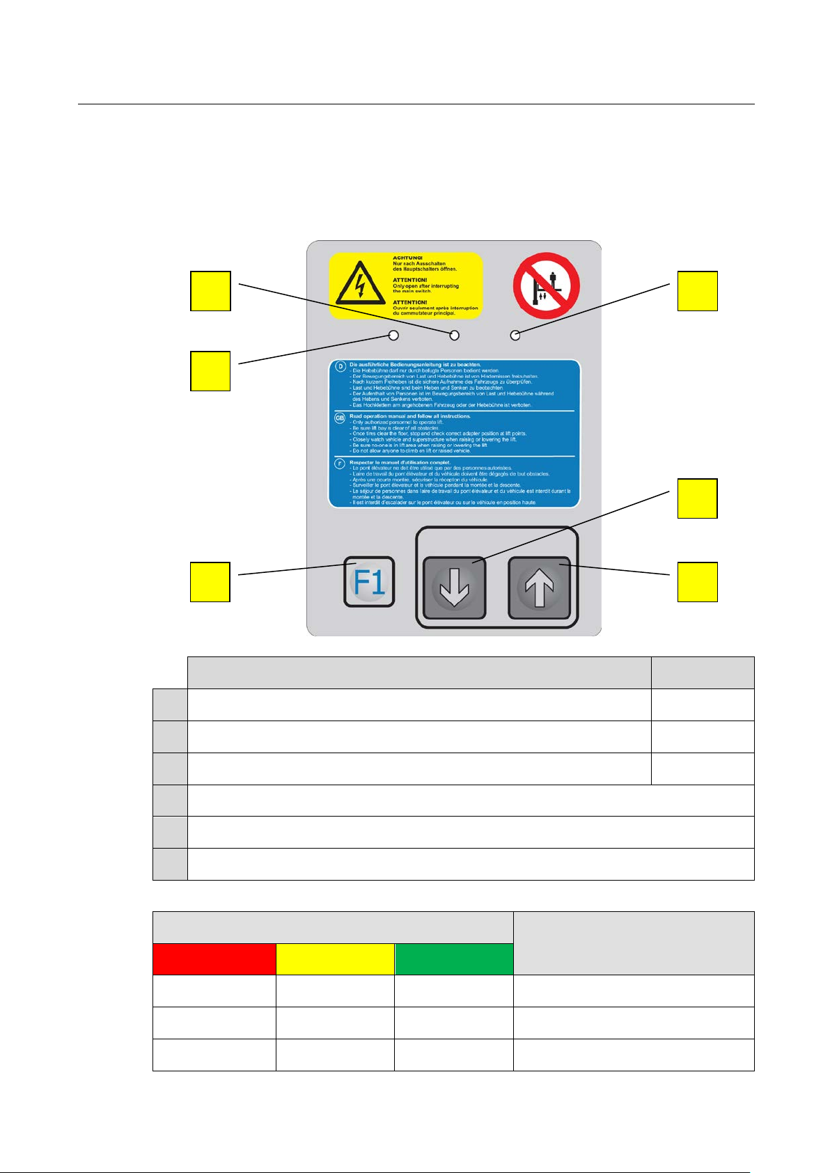
Pos: 53 /Technische Dokume ntatio n/Hebet echnik /00 HBZ Alle/I nhalte/I nhalt: Bedie neinhei t klein HBZ ( Bild) @ 24\mod_1303903425476_0.docx @ 999162 @ @ 1
E
D
C
Pos: 54 /Techn ische Dokume ntatio n/Hebet echnik/ 32 Stem pel-H ebebü hnen/ 000 1 Stemp el-H ebeb ühnen Al le/Inha lt/Inha lt: Bed ienein heit kle in St empel-H BZ (Tex t)_1 2pt @ 26\mod_1326273243887_75.docx @ 1150911 @ @ 1
F
B
A
Raise lift LIFT UP
Lower lift LIFT DOWN
(w/o function) F1
LED red (Malfunction or Error code); see LED Code below
LED yellow (Warning or Error code); see LED Code below
LED green (Ready for operation); see LED Code below
Pos: 55 /Technische Dokume ntatio n/Hebet echnik /32 S tempel-H ebebü hne n/000 1 Stem pel-H ebeb ühnen Al le/In halt/In halt: B ediene inheit k lein St empel-H BZ LE D-Cod e _12p t @ 44\mod_1464009307250_75.docx @ 2493766 @ @ 1
--- --- Lighting Ready for operation
Lighting Flashing 3x --- Inputs (Key contact)
Lighting Flashing 6x --- Liquid level indicator
BA320101-en
Page 14

14
LED Code
Status / Notice / Error
RED
YELLOW
GREEN
5.2.2
Large Version
Function
Short Form
A
B
C
D
E
F
G
H
Lighting Flashing 7x --- Motor temperature
Lighting Flashing 8x --- Switch monitoring "CE Stop"
Pos: 56 /Techn ische Dok ument atio n/Al le Ger äte/ Übers chr iften/ Über schri ften 1.1. 1/G/ Übersc hrif t 1.1 .1: Gr oße Ausf ühru ng @ 24\mod_1303992502163_75.docx @ 1000329 @ 2 @ 1
Pos: 57 /Technische Dokume ntatio n/Hebet echnik /00 HBZ Alle/I nhalte/I nha lt: B ed iene in heit gro ß HB Z ( Bild ) @ 23\m od_1297159153579_0.docx @ 972013 @ @ 1
H
G
F
I
J
K
D
C
B
E
Pos: 58 /Technische Dokume ntatio n/Hebet echnik /32 S tempel-H ebebü hne n/000 1 Stem pel-H ebeb üh nen Al le/In halt/ Inha lt: B edie nein heit groß S temp el-H BZ ( Tex t)_1 2pt @ 3 3\mod_1370949115830_75.docx @ 1789068 @ @ 1
Raise lift LIFT UP
Lower lift LIFT DOWN
Raise wheel-free jack WFJ UP
Lower wheel-free jack WFJ DOWN
Floor compensation On/Off
On (LED on): Floor compensation is always lowered
Off (LED off): Floor compensation is lowered when below CE
Stop, raised when above
Multifunctional key 2 F2
Multifunctional key 1 (not assigned) F1
LED red (Malfunction or Error code); see LED Code below
BA320101-en
A
FLOOR
Page 15

15
Function
Short Form
I
J
K
LED Code
Status / Notice / Error
RED
YELLOW
GREEN
LED yellow (Warning or Error code); see LED Code below
LED green (Ready for operation); see LED Code below
Illumination On/Off
On (LED on): Illumination is on when above CE Stop and is off when below
Off (LED off): Illumination is always off
Pos: 59 /Technische Dokume ntatio n/Hebet echnik /32 S tempel-H ebebü hne n/000 1 Stem pel-H ebeb üh nen Al le/In halt/ Inha lt: B edie nein heit groß S temp el-HBZ LED-C ode_12p t @ 44\mod_1464010093346_75.docx @ 2493858 @ @ 1
--- --- Lighting Ready for operation
Lighting Flashing 2x --- Inputs (Key contact) internal
Lighting Flashing 3x --- Inputs (Key contact) external
--- Lighting Lighting Axle lift not in position
Lighting Flashing 4x ---
--- Flashing 5x Lighting Ceiling light barrier
--- Flashing 6x Lighting Liquid level indicator
--- Flashing 7x ---
Lighting Flashing 8x --- Motor temperature
Axle lift not in position, below
CE Stop
Emergency stop switch
(Remote control)
Lighting Flashing 9x ---
Lighting Flashing 10x --- Switch monitoring "CE Stop"
Pos: 60 /-----For ma t-----/MA N UEL LER UMB RUC H Se ite num br uch @ 0\m od_1134403577687_0.docx @ 1277 @ @ 1
Switch monitoring "Lift fully
raised"
BA320101-en
Page 16

16
5.3
Remote Control (Option)
Controls and Indicators
Emergency Stop
5.4
Arm Restraint
Pos: 61 /Technische Dokument ation/Alle Gerät e/Übersc hriften/Üb erschriften 1. 1/F/Übers chrift 1.1: Fer nbed ie nung ( Opti on) @ 24\mod_1303988637956_75.docx @ 1000268 @ 2 @ 1
Pos: 62 /Technische Dokume ntatio n/Hebet echnik /00 HBZ Alle/I nhalte/I nhalt: Fernb edienu ng (Text) HBZ _ 12pt @ 26\m od_1326033712720_75.docx @ 1147495 @ @ 1
Same assignment as with stationary control unit (large version).
Pos: 63 /Technische Dokume ntatio n/Hebet echnik /00 HBZ Alle/I nhalte/I nhalt: Fernb edie nung (B ild) HBZ @ 24\mod_1303986843463_0.docx @ 999868 @ @ 1
Pos: 64 /Technische Dokument ation/Alle Gerät e/Übersc hriften/Üb erschriften 1. 1/T/Übers chrift 1.1: Tragarm arretierun g @ 9\mod_ 12101 6136 4709_7 5.docx @ 21210 7 @ 2 @ 1
Pos: 65 /Tec hnische Dokume ntat ion/Hebet echnik /00 HBZ Alle/I nhalte/I nhalt: Tragar marret ierung HBZ ( Text)_1 2pt @ 35\mod_1389364809798_75.docx @ 1873111 @ @ 1
Emergency stop is enabled by pushing the red mushroom button.
If the lift is in bottom position, the arm restraint is released and the swing arms are
free to swing.
If the lift is in a raised position, the locking mechanism is engaged and the swing
Pos: 66 /-----For ma t-----/MA N UEL LER UMB RUC H Se ite num br uch @ 0\m od_1134403577687_0.docx @ 1277 @ @ 1
arms cannot be moved.
BA320101-en
Page 17

17
5.5
Preparations
Swing Arm Superstructure
H-Shaped Superstructure
5.6
Raising
5.7
Lowering
Pos: 67 /Technische Dokume ntatio n/Alle Geräte/ Übersc hriften/ Überschr iften 1.1/V /Übersc hrift 1 .1: Vorb ereit ungen @ 8\mod_1204639543920_75.docx @ 155816 @ 2 @ 1
Pos: 68 /Technische Dokume ntatio n/Hebet echnik /32 S tempel-H ebeb üh nen/ 270 1 E S SQ UARE II 3. 0/BA/ In halt: 32 27 V orb ereitu ngen @ 28\mod_1337780371750_75.docx @ 1600199 @ @ 1
1 Fully lower the lift. Swing arms sideways to clear the approach path.
2 Slowly center the vehicle between the cylinders.
3 Apply the parking brake to prevent the vehicle from rolling off.
4 Position all four adapters under vehicle manufacturer's recommended lift
points.
5 The support discs are height-adjustable. Make sure they evenly engage the
vehicle frame.
6 Leave the vehicle and the danger zone around the lift.
1 Fully lower the lift. Slowly drive the vehicle over the supports so that these are in
center between the axles.
2 Apply the parking brake and use chocks to prevent the vehicle from rolling off.
3 Lift the extensions at their front edges and position them under the vehicle
manufacturer's recommended lift points.
IMPORTANT: Make sure the extensions snap into place!
4 Position spacer blocks under the lift points.
Pos: 69 /Tec hn isch e Do kument ation/A lle Ger äte/Über schr iften/ Überschri ften 1.1/H/Üb erschr ift 1.1: Hebe n @ 6\mod_1180960375312_75.docx @ 95073 @ 3 @ 1
Pos: 70 /Technische Dokume ntatio n/Hebet echnik /00 HBZ Alle/I nhalte/I nhalt: Hebe n Alle H BZ_12p t @ 27\mod_1327996945113_75.docx @ 1523675 @ @ 1
5 Leave the vehicle and the danger zone around the lift.
1 To raise the lift, push and hold the RAISE LIFT button, until the desired lifting
height is reached.
The lift movement stops when the button is released or the upper end stop is
Pos: 71 /Techn ische Dokume ntation/Al le Geräte/Übers chriften/ Überschrifte n 1.1/S/Übers chrift 1.1: Senk en @ 6\mod_1180960432671_75.docx @ 95086 @ 3 @ 1
Pos: 72 /Technische Dokume ntatio n/Hebet echnik /32 S tempel-H ebebü hne n/230 1 ZS SQUA RE II /BA/I nhalt: 3223 Senken ZS SQUARE I+II @ 27\mod_1327997000041_75.docx @ 1523719 @ @ 1
reached.
1 To lower the lift, push and hold the LIFT DOWN button until the desired height
is reached.
The lift movement stops when the button is released, the CE safety stop is
reached or the lower end stop is reached.
2 To lower the lift to bottom position after reaching the CE safety stop, release
Pos: 73 /-----For ma t-----/MA N UEL LER UMB RUC H Se ite num br uch @ 0\m od_1134403577687_0.docx @ 1277 @ @ 1
the LIFT DOWN button and push it again.
BA320101-en
Page 18

18
5.8
Bleeding the Cylinders
Pos: 74 /Technische Dokume ntatio n/Alle Geräte/ Übersc hriften/ Überschr iften 1.1/E /Übersc hrift 1 .1: En tlüften d er H ubzylind er @ 15\mod_1245836113669_75.docx @ 394834 @ 2 @ 1
Pos: 75 /Technische Dokume ntatio n/Hebet echnik /32 S tempel-H ebebü hnen/ 010 1 E S 9 3/B A/Inh alt: 3201 H ubzy lind er en tlüft en ( Text) @ 3 3\mod_1371799932858_75.docx @ 1794389 @ @ 1
The locking screw for bleeding the cylinder is located on the inside of the cylinder
guide and can be accessed through a hole in the head plate.
1 Fully extend the cylinders.
2 Remove the plugs. Slowly loosen the locking screws on both cylinders by a
maximum of one turn using an Allen key A/F 6.
3 Lower the lift so far until fluid escapes without any air and it is still possible to
tighten the screws.
4 Tighten the screws to 10 Nm torque.
5 Lower the lift completely and check the fluid level in the hydraulic unit; top up as
needed. Check locking screws for leaks after bleeding. Reinstall the plugs.
Pos: 76 /Tec hn isch e Do kument ation/H ebetech nik/3 2 Stemp el-Heb ebü hnen/ 0101 E S 9 3/BA/ Inha lt: 32 01 Hub zyl ind er en tlüft en/ma nuel l abse nke n (Bi lder) @ 3 5\mod_1389781121798_0.docx @ 1874556 @ @ 1
Pos: 77 /-----For ma t-----/MA N UEL LER UMB RUC H Se ite num br uch @ 0\m od_ 1134403577687_0.docx @ 1277 @ @ 1
BA320101-en
Page 19

19
5.9
Manual Lowering
5.9.1
Electrical (with Cable Set: 61 NOAB KA01)
24 VDC
0 VDC
0 VDC
24 VDC
Pos: 78 /Technische Dokume ntatio n/Alle Geräte/ Übersc hriften/ Überschr iften 1.1/M /Übersc hrift 1 .1: Ma nuelles A bsenke n @ 6\mod_1178113285703_75.docx @ 90869 @ 3 @ 1
Pos: 79 /Te chn isch e Dokum e ntat ion /Al le Ger äte/Inh alte/W arnung!/ Inha lt: War nung - Nur für autorisiertes Personal_12pt @ 26\mod_1326034622678_75.docx @ 1147655 @ @ 1
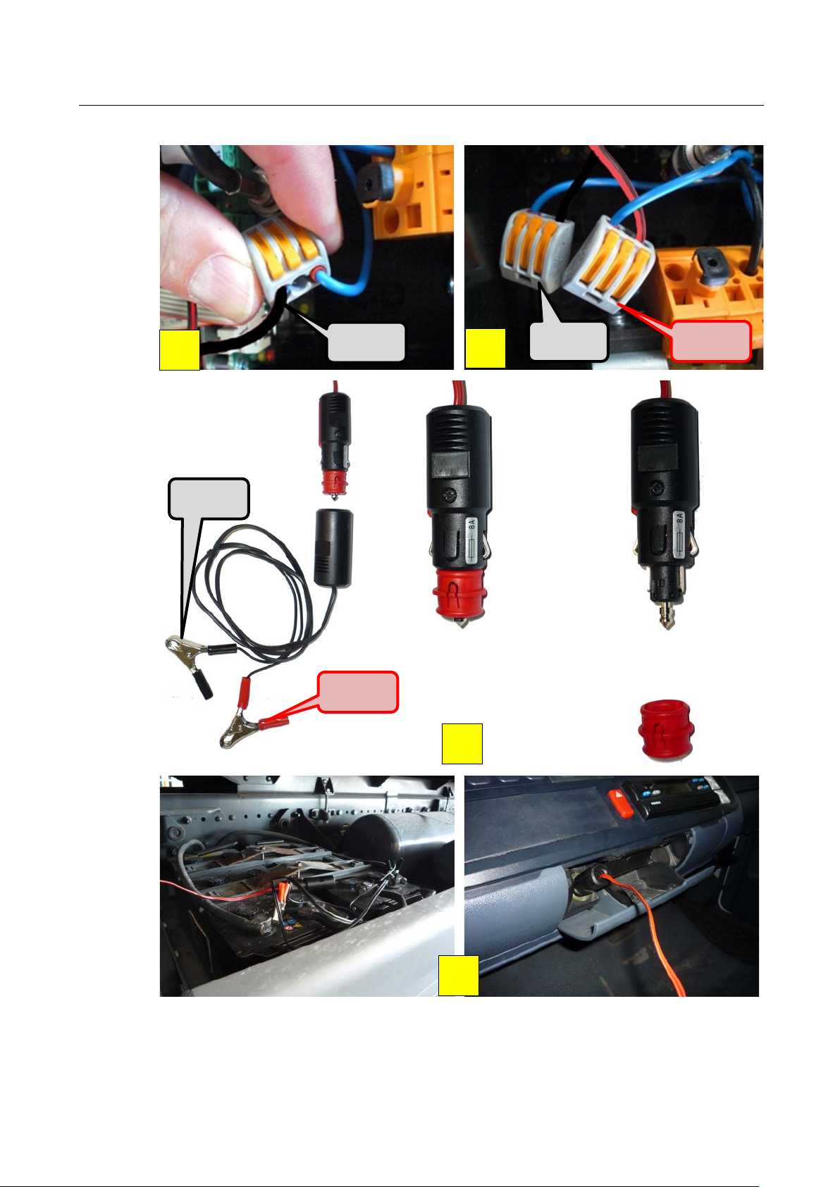
Authorized personnel only! Do not restart the lift before the error has been
remedied.
Pos: 80 /Technisch e Dok ument ation/Al le Gerät e/Über schrift en/Über schri ften 1. 1.1/E/ Überschr ift 1 .1.1: El ektrisch (m it Kab elsa tz 61 NOA B KA01) @ 30\mod_1360837093719_75.docx @ 1711511 @ 2 @ 1
Pos: 81 /Tec hn isch e Do kum ent ation/ Hebetech nik/3 2 Stemp el-Heb ebü hnen/ 0001 Stemp el-He beb ühnen Alle/ Inha lt/In ha lt: Man uell es Abs enke n m it 6 1 NOA B KA0 1 (Bi lder) @ 30\mod_1360572583765_0.docx @ 1710753 @ @ 1
1
2
3
4
BA320101-en
Page 20
20
24 VDC
0 VDC
24 VDC
24 VDC
0 VDC
A
A
B
B
5
6
7
Pos: 82 /-----For ma t-----/MA N UEL LER UMB RUC H Se ite num br uch @ 0\m od_1134403577687_0.docx @ 1277 @ @ 1
BA320101-en
8
Page 21

21
5.9.2
Mechanical
Pos: 83 /Technische Dokume ntatio n/Alle Geräte/ Überschrift en/Überschr iften 1.1. 1/M/Überschr ift 1.1.1: Mecha nisch @ 30\mod_1360837165869_75.docx @ 1711555 @ 2 @ 1
Pos: 84 /Technische Dokume ntatio n/Hebet echnik /32 S tempel-H ebebü hnen/010 1 E S 9 3/BA/I nhalt: 3201 Ma nuelles Absenk en M echanisc h ( Text) @ 3 3\mod_1372056983395_75.docx @ 1795209 @ @ 1
1 Remove the plugs. Slowly open the locking screws on both cylinders by a
maximum of one turn using an Allen key A/F 6.
The lift will begin to lower as soon as the screws on the two cylinders are
opened.
2 Remove the Allen key and leave the danger zone.
3 When the cylinders are in bottom position, tighten the screws to 10 Nm torque.
Reinstall the plugs.
Pos: 85 /Technische Dokume ntatio n/Hebet echnik /32 S tempel-H ebebühne n/010 1 ES 93/ BA/ Inhal t: 32 01 Hub zyl inde r entl üften/ ma nuel l abse nke n (Bi lder) @ 35\mod_1389781121798_0.docx @ 1874556 @ @ 1
Pos: 86 /-----For ma t-----/MA N UEL LER UMB RUC H Se ite num br uch @ 0\m od_1134403577687_0.docx @ 1277 @ @ 1
BA320101-en
Page 22

22
6
Maintenance
6.1
Annual Inspection
12 (twelve) months
Pos: 87 /Tec hn isch e Do kument ation/Al le Gerät e/Übersc hriften/ Übers chrifte n 1/I/Über schrift 1: Instand haltun g @ 28\mod_ 1332 15981 2536_ 75.docx @ 1565 908 @ 2 @ 1
Pos: 88 /Technische Dokume ntatio n/Alle Geräte/ Inhalte/ Warnu ng!/In halt: W arnung - Haup tscha lter aus bei I nst andhal tung_ 12pt @ 26\m od_1324465229892_75.docx @ 1140563 @ @ 1
Danger! Electric shock hazard!
Before doing any maintenance work, turn off the main switch and protect it
against tampering.
Pos: 89 /Technische Dokume ntatio n/Alle Geräte/ Übersc hriften/ Überschr iften 1.1/J/ Übersc hrift 1 .1: Jähr liche Überp rüfung @ 28\mod_1332230089694_75.docx @ 1566204 @ 2 @ 1
Pos: 90 /Technische Dokume ntatio n/Alle Geräte/ Inhalte/ Info!/I nhalt: I nfo - J ährlic he Überpr üfung_1 2pt @ 25\mod_1324460481075_75.docx @ 1139412 @ @ 1
• The maintenance interval prescribed by the manufacturer is
This maintenance interval refers to normal workshop usage. If the equipment is
used more frequently or under severe operating conditions (e.g. outdoors), the
interval must be reduced accordingly.
• Maintenance work shall be done only by authorized and trained service
technicians provided by the manufacturer, licensed dealers or service partners.
• In case of non-compliance the manufacturer's warranty becomes void.
Pos: 91 /Technische Dokume ntatio n/Hebet echnik /00 HBZ Alle/I nhalte/I nfo!/In halt: Info - DG UV Re gel 10 0-500 / DGUV Grundsatz 308-003_12pt @ 47\mod_1483611185270_75.docx @ 2804763 @ @ 1
Pos: 92 /-----For ma t-----/MA N UEL LER UMB RUC H Se ite num br uch @ 0\m od_1134403577687_0.docx @ 1277 @ @ 1
.
BA320101-en
Page 23

23
6.2
Maintenance Schedule
Interval
Maintenance items
Procedure
6.3
Care Instructions
Pos: 93 /Technische Dokument ation/Alle Gerät e/Übersc hriften/Üb erschriften 1. 1/I/Überschr ift 1.1: Instand haltungsp lan @ 11\mod_ 123 1318 9194 01_ 75.d ocx @ 289622 @ 2 @ 1
Pos: 94 /Technische Dokume ntatio n/Hebet echnik /32 S tempel-H ebebü hne n/000 1 Stem pel-H ebeb üh nen Al le/In halt/ Inha lt: I nstand hal tungs pla n Stem pel-H BZ_ 12p t @ 2 6\mod_1326273650740_75.docx @ 1151111 @ @ 1
3 months
Check fluid level, top up if necessary.
Check hydraulic system for leakage.
Hydraulic system
Check power unit for unusual noise
during operation. Check fastening
screws for tight fit.
Support discs Check threads for smooth running.
6 months Hydraulic fluid
12 months General inspection Check all components for damage.
6 years Pressure hoses Replace all pressure hoses.
Pos: 95 /Technische Dokume ntatio n/Alle Geräte/ Übersc hriften/ Überschr iften 1.1/P/ Übersc hrift 1.1: Pfle gehinwe ise @ 15\m od_12 4591 22348 54_75. docx @ 39 5780 @ 2 @ 1
Pos: 96 /Techn ische Dokume ntation/Al le Geräte/Inh alte/Inhalt: Pfl egehinweis e - Alle Geräte_1 2pt @ 26\mod_1324468886116_75.docx @ 1141252 @ @ 1
• Periodically clean the equipment and treat it with a care product.
• Repair damage to the paintwork immediately to prevent corrosion.
• Usage of caustic cleaning agents or high pressure and steam jet cleaners may
Pos: 97 /Technische Dokume ntatio n/Hebet echnik /32 S tempel-Hebebühnen/0301 ZS94 / ZS4 / ZS5/ BA/I nha lt : 32 03 K olbe nst an ge re ini gen Stem pel-H BZ @ 28\ mod_1332501642810_75.docx @ 1570235 @ @ 1
lead to equipment damage.
• Acid-forming detergents may not be used, as this can damage the chromium
layer of the ram.
• No warranty for damage caused by rust. The ram must always be protected by
a thin film of oil.
Flat head supports
Check extensions for smooth running,
grease as required.
Check fluid for contamination and
ageing, replace if necessary.
Pos: 98 /Technische Dokume ntatio n/Alle Geräte/ Inh alte/I nfo!/ Inhal t: I nfo - Pflegehinweise_12pt @ 26\mod_1324461215655_75.docx @ 1139602 @ @ 1
Pos: 99 /-----For ma t-----/MA NUEL LER UM BRUCH Sei tenum bruc h @ 0\mod_1134403577687_0.docx @ 1277 @ @ 1
• Remains of underbody protection and other debris can destroy seals. The
result of this is that detergents and salt water can penetrate unhindered and
cause damage to the lift.
Regular care and maintenance is the key condition for functionality and long life
expectancy of the equipment!
BA320101-en
Page 24

24
6.4
Checking the Fluid Level
6.5
Greasing Points
Pos: 100 /Technische Dokum entati on/Alle G eräte/ Übers chrifte n/Über schrifte n 1.1/Ö/ Übers chrift 1.1: Öls tand p rüfe n @ 20\m od_1268827315211_75.docx @ 827233 @ 1 @ 1
Pos: 101 /Tech nis che D okume nta tion/H ebe techn ik/00 H BZ A lle /Inh alte/I nfo!/ Inha lt: I nfo - Tausch v on Ö l und Dr ucksch läuchen_ 12pt @ 26\mod_1325753763930_75.docx @ 1147073 @ @ 1
• Replace the hydraulic fluid periodically, depending on aging, soiling and water
absorption.
• When topping up, use fluid with the same specification only.
• If the lift is operated permanently at an ambient temperature of < 15 °C (59 °F),
use hydraulic fluid with a lower viscosity.
• The pressure hoses should be replaced as required, but after six years at the
latest.
Pos: 102 /Technische Dokum entati on/Hebe technik/ 32 Stem pel-Heb ebüh nen/00 01 Stem pel-Heb ebühne n Al le/Inhal t/Inhal t: Hydr aulikö l nachfü llen Stemp el_H BZ @ 2 6\mod_1326035058602_75.docx @ 1147815 @ @ 1
1 Fully lower the lift and any accessory equipment.
2 Remove the center cover.
3 Remove the filler screw at the hydraulic power unit.
4 When checking the fluid level using the dipstick, do not screw in the filler screw.
The fluid level should be between the top and bottom level marks.
5 Refill fluid with HLPD 22 / HLP 22 (biodegradable) specification. Capacity is
indicated on the reservoir.
Pos: 103 /Technische Dokum entati on/Alle G eräte/ Übers chrifte n/Über schrifte n 1.1/SCH /Üb erschr ift 1. 1: Schm ierste llen @ 14\m od_1241506822762_75.docx @ 370057 @ 1 @ 1
Pos: 104 /Technische Dokum entati on/Hebe technik/ 32 Stem pel-Heb ebüh nen/00 01 Stem pel-Heb ebühne n Al le/Inhal t/Inhal t: 3200 S chm ierstel len Stem pel-H BZ @ 28\mod_1335184053867_75.docx @ 1588853 @ @ 1
6 Completely screw in the filler screw.
• Lightly oil the entire length of the ram and gear rack every six months or as
required (e.g. in the event of noise).
• Inspect the support arm extensions every six months for smooth operation and
lubricate if necessary.
• Inspect the support plate threads every six months for smooth operation and
lubricate if necessary.
Pos: 105 /Technische Dokum entati on/Hebe technik/ 32 Stem pel-Heb ebüh nen/2701 ES SQUARE II 3.0/BA/Inhalt: 3227 Schmierstellen (Bild) @ 28\mod_1337674652 817_0. docx @ 1 59885 9 @ @ 1
• Inspect the rubber pads every six months for wear and replace if necessary.
Pos: 106 /-----F orm at-----/M ANUELLE R UMBR UCH Seite numbru ch @ 0\mod_1134403577687_0.docx @ 1277 @ @ 1
BA320101-en
Page 25

25
6.6
Troubleshooting
Error
Diagnosis
Remedy
Pos: 107 /Te ch nisc he D okumen tation/A lle G eräte/ Überschr iften/Üb erschr iften 1 .1/F/ Übersc hrift 1.1 : Feh lerbeheb ung @ 8\mod _120 67146 46748 _75.d ocx @ 1 79620 @ 1 @ 1
Pos: 108 /Technische Dokumentation/Hebetechnik/Archiv/32 Stempel-Hebebühnen/1001 ZS S QUA RE/BA/ Inhalt: 3210 F ehlerb ehebun g ZS SQ UARE I +II @ 26\mod_1326035685608_75.docx @ 1147879 @ @ 1
Lighting between runways
does not burn.
Fuse F2 defective. Replace fuse F2 .
Lift cannot be fully raised. Low fluid level.
Lift shows jerky
movements.
Air in hydraulic system. Bleed cylinders.
Main switch off. Turn on main switch.
Emergency stop switch of
remote control actuated.
Mains fuse blown. Replace mains fuse.
Lift does not respond.
Primary fuse F1 of power
supply -T1 blown.
Secondary fuses of power
supply -T1 blown.
Ceiling light barrier +D-B1
(optional) dirty.
Check fluid level, top up
as required.
Unlock emergency stop
switch.
Replace fuse F1.
Replace fuses.
Cautiously clean light
barrier.
Motor runs, but pressure
build-up insufficient to
raise lift.
Lift with pneumatic floor
cover and axle jack
cannot be fully lowered.
Pos: 109 /-----For mat- ----/MA NUELLE R UMBR UCH Seitenum bruch @ 0\mod_1134403577687_0.docx @ 1277 @ @ 1
Pressure relief valve set
too low.
Hydraulic system leaking.
Low fluid level.
Vehicle too heavy.
Axle jack is not in rest
position.
Position switch for axle
jack defective or
maladjusted.
Contact service.
Remove leakage, contact
service.
Check fluid level, top up
as required.
Reduce load, observe
rated load capacity.
Move axle jack to rest
position.
Contact service.
BA320101-en
Page 26

26
6.7
Spare Parts
7
Service Lifetime
8
Dismantling
9
Disposal
10
Contents of the Declaration of Conformity
MAHA Maschinenbau Haldenwang GmbH & Co. KG
Model:
Designation:
Directives:
Standards:
Pos: 110 /Technische Dokum entati on/Alle G eräte/ Übers chrifte n/Über schrifte n 1.1/E/ Über schrift 1.1: Ers atzte ile @ 18\mod_1255596847002_75.docx @ 474414 @ 1 @ 1
Pos: 111 /Technische Dokum entati on/Alle G eräte/I nha lte/Inha lt: Ersatz teile - Alle Ger äte_12pt @ 26\mod_1324468768120_75.docx @ 1141219 @ @ 1
To ensure safe and reliable operation, only use original spare parts supplied by the
Pos: 112 /Technische Dokum entati on/Alle G eräte/ Übers chrifte n/Über schrifte n 1/L/ Übersc hrift 1: Leben sdauer @ 19\ mod_ 12663 36761 550_ 75.do cx @ 7424 23 @ 1 @ 1
Pos: 113 /Te ch nisc he D ok umen tati on/H ebe te chn ik/ 00 H BZ A lle/Inh alte/Inh alt: Lebe nsdau er HBZ _12pt @ 26\mod_1325656335645_75.docx @ 1146173 @ @ 1
equipment manufacturer.
In its standard version, this product is designed for 22,000 load cycles based on
EN 1493. The maximum period of normal use in relation to the possible product
life expectancy shall be evaluated and scheduled by a qualified person during the
Pos: 114 /Technische Dokum entati on/Alle G eräte/ Übers chrifte n/Über schrifte n 1/D/Üb ers chrift 1: Demon tage @ 19\m od_12 66336 8228 63_75. docx @ 74 2452 @ 1 @ 1
Pos: 115 /Technische Dokum entati on/Alle G eräte/I nha lte/Inha lt: Dem ontage - Alle Ger ät e_12p t @ 26\ mod_1324466078229_75.docx @ 1140857 @ @ 1
annual safety inspection.
Decommissioning and dismantling of the equipment may be done only by
specially authorized and trained personnel provided by the manufacturer, licensed
Pos: 116 /Technische Dokum entati on/Alle G eräte/ Übers chrifte n/Über schrifte n 1/G/ Überschr ift 1 : Gerä teentsor gung @ 6\mod_1174482271625_75.docx @ 76901 @ 1 @ 1
dealers or service partners.
Pos: 117 /Te chnis che Dok umen tation/A lle Ger äte/In halte/I nhalt: G eräte entsorg ung d urch Be treiber allg_1 2pt @ 26\mod_1324467874153_75.docx @ 1140955 @ @ 1
Pay attention to the product and safety data sheets of the lubricant used. Avoid
damage to the environment. Should a disposal of the device be necessary it must
be done in adherence with locally applicable legal regulations regarding
environmental protection. Remove all materials properly sorted out and bring them
to a suitable waste disposal service. Collect operating materials such as grease,
oils, coolant, solvent-based cleaning fluids etc. in suitable containers and dispose
Pos: 118 /Technische Dokum entati on/Alle G eräte/I nha lte/Inha lt: Ger äteents orgung über F achbetr ieb (a lter nat iv) _12p t @ 2 6\mod_1324468120852_75.docx @ 1141022 @ @ 1
of in an environmentally protective manner.
Alternatively, you may take the equipment to a specialised waste management
plant to ensure that all components and operating liquids are properly disposed
Pos: 119 /Te ch nisc he D ok umen tati on/Alle G eräte/ Übers chrifte n/Über schrifte n 1/I/ Überschr ift 1: I nhal t der K onformi tätserkl ärung @ 22\mod_1292856748432_75.docx @ 958616 @ 1 @ 1
Pos: 120 /Technische Dokum entati on/Alle G eräte/I nha lte/Inha lt: In halt der K onfor mit äts erk läru ng a llg_ 12p t @ 26\mod_1324468436145_75.docx @ 1141120 @ @ 1
of.
herewith declares as a manufacturer its sole responsibility to ensure that the
product named hereafter meets the safety and health regulations both in design
and construction required by the EC directives stated below.
This declaration becomes void if any change is made to the product that was not
Pos: 121 /Te ch nisc he D ok umenta tion/Hebe techn ik/32 Stemp el-Hebebühnen/0101 ES 93/BA/Inhalt: 3201 Inhalt der Konformitätserklärung @ 45\mod_1470227371124_75.docx @ 2548260 @ @ 1
Pos: 122 /-----F orm at-----/M ANUELLE R UMBR UCH Seite numbru ch @ 0\mod_1134403577687_0.docx @ 1277 @ @ 1
discussed and approved by named company beforehand.
ES 93 / SOLIST
One Post Inground Lift; Rated Load Capacity 3000 kg
2006/42/EC; 2014/30/EU
DIN EN 1493; DIN EN 60204-1
BA320101-en
Page 27

11 Company Information
© MAHA Maschinenbau Haldenwang GmbH & Co. KG
Legal notice based on ISO 16016:
The reproduction, distribution and utilization of this document as well as the communication of its
contents to others without explicit authorization is prohibited. Offenders will be held liable for the
payment of damages. All rights reserved in the event of the grant of a patent, utility model or design.
The contents of this edition have been checked with great care. However, errors cannot be fully
excluded. Subject to technical change without notice.
Document
Document No.: BA320101-en
Approval Date: 2017-02-23
Manufacturer
MAHA Maschinenbau Haldenwang GmbH & Co. KG
Hoyen 20
87490 Haldenwang
Germany
Phone: +49 8374 585 0
Fax: +49 8374 585 590
Mail: maha@maha.de
Web: http://www.maha.de
27
Service
MAHA Service Center
AutomoTec GmbH
Maybachstraße 8
87437 Kempten
Germany
Phone: +49 8374 585 100
Fax: +49 8374 585 491
Mail: service@automo-tec.com
Web: www.automo-tec.com
BA320101-en
 Loading...