

Page 1
Fehler! Verwenden Sie die Registerkarte 'Start', um Name dem Text zuzuweisen, der hier angezeigt werden soll.Fehler! Verwenden Sie
die Registerkarte 'Start', um Name dem Text zuzuweisen, der hier angezeigt werden soll.Fehler! Verwenden Sie die Registerkarte
'Start', um Name dem Text zuzuweisen, der hier angezeigt werden soll.
ECONLIFT 6500
Two Post Lift
Original Operating Instructions
BA361601-en
Pos: 1 /Technische D okumen tation/H ebetec hnik/3 6 S äule n-Hebe bühne n/1 601 EC ON LIFT 6500/BA/Inhalt: 3616 Titelbild @ 46\mod_1481288659643_0.docx @ 2797767 @ @ 1
Pos: 2 /-----For mat---- -/MAN UELLER UM BRUCH Sei tenumb ruch @ 0\mod _11 34403 5776 87_0.d ocx @ 127 7 @ @ 1
Page 2

2
BA361601-en
Pos: 3 /-----For mat---- -/Inha ltsv er zeic hnis - 3 Ebe ne n @ 5\mod_ 116 88674 41046_ 75.do cx @ 729 20 @ @ 1
Contents
1 Safety ...................................................................................................................... 5
1.1 Introduction ......................................................................................................................................... 5
1.2 Symbols .............................................................................................................................................. 5
1.3 Intended Use ....................................................................................................................................... 5
1.4 Inappropriate Use ................................................................................................................................ 5
1.5 Requirements on Operating and Service Personnel ............................................................................. 5
1.6 Safety Instructions for Commissioning ................................................................................................. 6
1.7 Safety Instructions for Operation ......................................................................................................... 6
1.8 Safety Instructions for Servicing ........................................................................................................... 7
1.9 What to Do in the Event of Defects or Malfunctions ............................................................................. 7
1.10 What to Do in the Event of an Accident ............................................................................................... 7
1.11 Safety Features ................................................................................................................................... 8
1.11.1 Dead Man's Type Control .................................................................................................................... 8
1.11.2 Electronic Synchronization System ...................................................................................................... 8
1.11.3 Safety Nut ........................................................................................................................................... 8
1.11.4 Load Nut Failure Protection ................................................................................................................. 8
1.11.5 Load Nut Wear Check ......................................................................................................................... 8
1.11.6 Overload Protection of Motors ............................................................................................................. 8
1.11.7 Drive Belt Failure Protection................................................................................................................. 8
1.11.8 Pinch Point Protection ......................................................................................................................... 8
1.11.9 Automatic Arm Restraint ..................................................................................................................... 8
2 Description ............................................................................................................... 9
2.1 General Information ............................................................................................................................. 9
2.2 Specifications ...................................................................................................................................... 9
3 Transport and Storage ........................................................................................... 12
4 Installation and Initial Operation .............................................................................. 12
5 Operation ............................................................................................................... 12
5.1 Main Switch....................................................................................................................................... 12
5.2 Controls and Indicators ..................................................................................................................... 13
5.3 Text Display ....................................................................................................................................... 14
5.3.1 Normal Operation .............................................................................................................................. 14
5.3.2 Referenzierung .................................................................................................................................. 15
5.3.3 Error Messages with Service Requirement: E000…E199 .................................................................. 15
5.3.4 Error Messages: E200…E299 ........................................................................................................... 16
5.4 Menu Navigation ............................................................................................................................... 17
5.4.1 Exploded View .................................................................................................................................. 17
5.4.2 Preselecting the Automatic Stop ....................................................................................................... 17
5.4.3 Disabling the Automatic Stop ............................................................................................................ 17
5.4.4 Displaying the Serial Number of the Lift ............................................................................................. 18
Page 3

3
BA361601-en
5.4.5 Displaying the Serial Number of the Lift Control ................................................................................. 18
5.4.6 Displaying the Cloud ID ..................................................................................................................... 18
5.5 Arm Restraint .................................................................................................................................... 19
5.6 Preparations ...................................................................................................................................... 20
5.7 Raising .............................................................................................................................................. 22
5.8 Vehicle in Raised Position .................................................................................................................. 22
5.9 Lowering ........................................................................................................................................... 22
5.10 Manual Lowering ............................................................................................................................... 23
6 Maintenance .......................................................................................................... 24
6.1 Annual Inspection .............................................................................................................................. 24
6.2 Maintenance Schedule ...................................................................................................................... 25
6.3 Care Instructions ............................................................................................................................... 25
6.4 Lubrication ........................................................................................................................................ 26
6.4.1 Lubricants ......................................................................................................................................... 26
6.4.2 Lifting Screw Lubrication ................................................................................................................... 26
6.4.3 Upper Support of Lifting Screw ......................................................................................................... 27
6.4.4 Greasing the Arm Extensions ............................................................................................................ 27
6.4.5 Greasing the Disc Adapter Threads ................................................................................................... 27
6.5 Operational and Wear Checks ........................................................................................................... 28
6.5.1 Load Nut Wear Check ....................................................................................................................... 28
6.5.2 Checking the Rubber Pads of the Support Discs .............................................................................. 29
6.5.3 Checking the Brakes of the Lifting Screws ........................................................................................ 29
6.5.4 Checking the Drive Belt ..................................................................................................................... 29
6.5.5 Checking the Circuit Breaker ............................................................................................................. 30
6.6 Spare Parts ....................................................................................................................................... 30
7 Service Lifetime ...................................................................................................... 31
8 Dismantling ............................................................................................................ 31
9 Disposal ................................................................................................................. 31
10 Contents of the Declaration of Conformity .............................................................. 31
11 Company Information ............................................................................................. 32
Pos: 4 /-----For mat---- -/MAN UELLER UM BRUCH Sei tenumb ruch @ 0\mod _11 34403 5776 87_0.d ocx @ 127 7 @ @ 1
Page 4

4
BA361601-en
Pos: 5 /-----For mat---- -/MAN UELLER UM BRUCH Sei tenumb ruch @ 0\mod _11 344 035 776 87_0.d ocx @ 1277 @ @ 1
Page 5
5
BA361601-en
Pos: 6 /Technische D okumen tation/A lle Gerä te/ Überschrif ten/Über schr iften 1/S /Über schrift 1: Si cherhei t @ 6\mod_1174482399906_75.docx @ 76962 @ 1 @ 1
1
Safety
Pos: 7 /Technis che Dokum en tation/ All e Gerä te/ Über schrif ten/ Übers chrif ten 1.1/E /Über schr ift 1.1: E inführ ung @ 6\m od_1174482219062_75.docx @ 76793 @ 2 @ 1
1.1
Introduction
Pos: 8 /Technische D okumen tation/H ebetec hnik/3 6 S äule n-Hebe bühne n/2 601 EC ON III/ BA/Inh alt: 362 6 Einf ühru ng @ 27\mod_1328083636960_75.docx @ 1532697 @ @ 1
Thoroughly read this manual before operating the lift and comply with the
instructions. Always display the manual in a conspicuous location.
Personal injury and property damage incurred due to non-compliance with these
safety instructions are not covered by the product liability regulations.
Pos: 9 /Technische D okumen tation/A lle Gerä te/ Überschrif ten/Über schr iften 1 .1/S/ Überschri ft 1. 1: Symb ole @ 6\mod_1174482270875_75.docx @ 76865 @ 2 @ 1
1.2
Symbols
Pos: 10 /Technische Dokume ntation/ Alle Ger äte/I nhalte/S icher heit/In halt: Sy mbole S icherh eit_12p t @ 2 5\mod_1324456650897_75.docx @ 1139046 @ @ 1
Important safety instructions. Failure to comply with instructions could result in
personal injury or property damage.
Important information.
Pos: 11 /Technische Dokumentat ion/Alle Gerät e/Übersc hriften/Über schriften 1. 1/B/Überschr ift 1.1: Bestimm ungsgemä ßer Gebrauch @ 6\mod_117 6734 02220 3_75.d ocx @ 887 46 @ 2 @ 1
1.3
Intended Use
Pos: 12 /Techn ische Dokument ation/ Hebetech nik/3 6 Säul en-Hebeb ühne n/0001 S äulen-H ebebü hnen All e/Inhal te/In halt: Bes timmun gsgemä ßer Geb rauch Scher en-/S äule n-HBZ _12p t @ 26\mod_1326280285347_75.docx @ 1151787 @ @ 1
• This lift is to be used exclusively for the safe lifting of motor vehicles. Observe
the rated load capacity.
• The lift may not be modified without the express written consent of the
manufacturer. In case of non-compliance the declaration of conformity
becomes void.
Pos: 13 /Technische Dokume ntation/ Alle Geräte/Üb erschrift en/Überschr iften 1.1/B/ Überschrif t 1.1: Bestimmun gswidriger Geb rauch @ 18\mod_1255530265027_75.docx @ 471571 @ 2 @ 1
1.4
Inappropriate Use
Pos: 14 /Technische Dokume ntation/ Hebet echnik/ 00 HBZ Alle/In halte/In halt: B estim mungsw idriger Gebrau ch HBZ _12pt @ 26\mod_1325512462855_75.docx @ 1143595 @ @ 1
Any use other than described is inappropriate, for example:
• Climbing on the lift supports
• Transporting persons on the lift supports
• Usage as mobile work platform or for other lifting operations
Pos: 15 /Technische Dokume ntation/ Alle Ger äte/Üb ersc hriften/ Überschr iften 1.1/A/Üb ersc hrift 1.1: Anf orderun gen a n das Bed ienun gs- und Serv iceper sonal @ 34\mod_1380637497630_75.docx @ 1835413 @ 2 @ 1
1.5
Requirements on Operating and Service Personnel
Pos: 16 /Technische Dokume ntation/ Alle Ger äte/I nhalte/S icher heit/In halt: Anf order ungen a n das Bedie nungs- u nd Servi cepers onal_1 2pt @ 4 7\mod_1482392891402_75.docx @ 2803198 @ @ 1
All persons employed in the operation, maintenance, installation, removal and
disposal of the device must
• be mentally and physically suited for these activities,
• be at least 18 years old,
• be trained and instructed in writing,
Page 6

6
BA361601-en
• have read and understood the operating instructions, especially the instructions
what to do in the event of defects or malfunctions,
• be on record as having been instructed in safety guidelines,
• have practical experience in working with vehicle lifts and the hazards inherent
in such equipment.
Pos: 17 /Technische Dokume ntation/ Alle Ger äte/Üb ersc hriften/ Über schr ifte n 1. 1/S/Üb ersc hrif t 1. 1: Sic herhe itsv orschr ift en für die I nbe trieb nahm e @ 6\m od_1174482269156_75.docx @ 76838 @ 2 @ 1
1.6
Safety Instructions for Commissioning
Pos: 18 /Technische Dokume ntation/ Hebet echnik/ 00 HBZ Alle/In halte/In halt: S ich erhe itsvor schrif ten f ür d ie I nbetri ebna hme H BZ_1 2pt @ 47\ mod_1483524035338_75.docx @ 2804458 @ @ 1
• The lift shall be installed and commissioned by authorised service personnel
only.
• Use personal protective equipment.
• All safety features must be checked for proper function at commissioning.
• The control desk (if present) shall not be installed in the danger zone of the lift.
• The standard lift version shall not be installed and commissioned in hazardous
locations, outdoors, in moist rooms (e.g. car wash) or outside a temperature
range of 5…40 °C (41…104 °F).
Pos: 19 /Technische Dokume ntation/ Alle Ger äte/Üb ersc hriften/ Überschr iften 1.1/S/Üb ersc hrift 1.1: Sic herheits vorschr iften f ür den Betri eb @ 6\m od_1174482268953_75.docx @ 76826 @ 2 @ 1
1.7
Safety Instructions for Operation
Pos: 20 /Technische Dokume ntation/ Hebet echnik/ 36 Säul en-Heb ebühne n/0001 S äulen- Hebebü hnen All e/Inhal te/In halt: Si cherhei tsvorsc hriften für de n Betr ieb Säu len-HB Z_ 12p t @ 4 6\mod_1481283829688_75.docx @ 2797291 @ @ 1
• Use personal protective equipment.
• Operation of the lift is permitted only with all protective covers (motor, spindle,
cylinder cover) correctly installed and undamaged.
• Drive on the lift only when it is in bottom position.
• Ensure an unobstructed movement of lift and vehicle.
• After raising the vehicle briefly, stop and check the lift supports for secure
contact with the vehicle.
• Make sure the vehicle doors are closed during raising and lowering cycles.
• Closely watch lift and vehicle during raising and lowering cycles.
• Do not allow anyone to stay in lift area during raising and lowering cycles.
• Do not allow anyone to climb on lift or inside raised vehicle.
• Comply with the applicable accident prevention regulations.
• Do not exceed the rated load capacity as indicated on the lift nameplate.
• Only use the vehicle manufacturer's recommended lift points.
• Do not use the lift for transporting persons.
• Lifts with runways: After positioning the vehicle on the lift secure it against roll-
off.
• Keep lift and vehicle free of tools and parts.
• Lifts with support arms: Use caution when removing or installing heavy
components. Center-of-gravity displacement may occur. Secure the vehicle
using lashing straps.
Page 7

7
BA361601-en
• Keep the lift and lift area clean. Slip hazard on oily surface!
• The main switch serves as emergency switch. In case of emergency turn it to
position "0".
• Protect all parts of the electrical equipment from humidity.
• Protect the lift against unauthorized usage by padlocking the main switch.
• Use caution with operating vehicle engines. Danger of poisoning!
Pos: 21 /Technische Dokume ntation/ Alle Ger äte/Üb ersc hriften/ Überschr iften 1.1/S/Üb ersc hrift 1.1: Sic herheits vorschr iften f ür Servi cearbeit en @ 6\mod_1174482270640_75.docx @ 76850 @ 2 @ 1
1.8
Safety Instructions for Servicing
Pos: 22 /Tec hnische Dokume ntat ion/Heb etechni k/00 HBZ Alle/ Inhalte/ Inha lt: Sich erheitsv orschr iften f ür Serv icearb eiten HBZ _1 2pt @ 46\m od_1481283945452_75.docx @ 2797338 @ @ 1
• Use personal protective equipment.
• Service work must be done by authorized service technicians.
• Turn off and padlock the main switch before doing any repair, maintenance or
setup work.
• The system must be unpressurized during maintenance work.
• Work on pulse generators or proximity switches must be done by authorized
service technicians.
• Work on the electrical equipment must be done by service technicians or
qualified electricians.
• Ensure that ecologically harmful substances are disposed of in accordance with
the appropriate regulations.
• Do not use high pressure or steam jet cleaners. Do not use caustic cleaning
agents.
• The lift's safety devices must be set by authorized service technicians.
• Do not replace or override the safety devices.
Pos: 23 /Technische Dokume ntation/ Alle Ger äte/Üb ersc hriften/ Überschr iften 1.1/V/ Übersc hrift 1 .1: Verh alten im Stör fall @ 6\mod_1178097008375_75.docx @ 90829 @ 2 @ 1
1.9
What to Do in the Event of Defects or Malfunctions
Pos: 24 /Technische Dokume ntation/ Hebet echnik/ 00 HBZ Alle/In halte/In halt: V erhalt en im Störfal l HBZ_ 12pt @ 26\m od_13 25513 6825 83_75. docx @ 11 43723 @ @ 1
• In case of defects or malfunctions such as uncontrolled lift movement or
deformation of the superstructure, support or lower the lift immediately.
• Turn off the main switch and secure it against unauthorized usage. Contact
service.
Pos: 25 /Techn ische Dokument ation/Alle Ger äte/Übersc hriften/ Überschrifte n 1.1/V/Übers chrift 1.1: Verh alten bei Unfällen @ 1 9\mod_ 12671 77245 337_7 5.doc x @ 79460 0 @ 2 @ 1
1.10
What to Do in the Event of an Accident
Pos: 26 /Technische Dokume ntation/ Alle Ger äte/I nhalte/S icher heit/ Inhal t: V erha lten be i U nfä llen_ 12pt @ 34\mod_1381128863435_75.docx @ 1837175 @ @ 1
• The injured person is to be removed from the danger area. Find out where
dressing and bandages are kept. Seek first-aid.
• Provide first-aid (stop bleeding, immobilise injured limbs), report the accident
and seal off the accident site.
• Immediately report any accident to your supervisor. Make sure a record is kept
of every occasion first-aid is provided, e.g. in an accident book.
• Remain calm and answer any questions that may arise.
Pos: 27 /Technische Do kument ation/A lle Gerät e/Übersc hriften/ Übers chrifte n 1.1/S/Üb erschr ift 1.1: Sic herheit seinric htunge n @ 6\mod_ 11744 83324 765_ 75.do cx @ 7710 3 @ 2 @ 1
Page 8

8
BA361601-en
1.11
Safety Features
Pos: 28 /Technische Dokume ntation/ Hebet echnik/ 00 HBZ Alle/In halte/In halt: S icher heitseinr ichtu ngen - Ve rä nderun gen v erbo ten H BZ @ 47\ mod_1483610856889_75.docx @ 2804716 @ @ 1
• The safety features shall not be modified by the owner/operator!
Pos: 29 /Technische Dokume ntation/ Hebet echnik/ 36 Säul en-Heb ebüh nen/ 160 1 ECON LIFT 65 00/BA/ Inh alt: 3 616 S icher hei tseinr icht unge n @ 46\mod_1481106169539_75.docx @ 2794441 @ 333333333 @ 1
1.11.1
Dead Man's Type Control
The operator is required to hold the main switch in the engaged position to raise
or lower the lift.
1.11.2
Electronic Synchronization System
The synchronization system ensures level movement of both carriages.
Synchronization is electronically controlled by the motors switching on and off.
Depending on load and operating temperature, the lift control may respond
several times.
1.11.3
Safety Nut
In case of load nut failure the safety nut takes up the load and thus ensures safe
lowering of lift.
1.11.4
Load Nut Failure Protection
After load nut failure the carriages are locked in bottom position by the control
system. Lift operation will not be possible until the load nut has been replaced and
the control system has been reinitialized.
1.11.5
Load Nut Wear Check
The load nut can be visually checked for wear to have it replaced in time.
1.11.6
Overload Protection of Motors
The motors are equipped with overload protection switches.
1.11.7
Drive Belt Failure Protection
In case of drive belt failure the motors switch off immediately.
1.11.8
Pinch Point Protection
During lowering cycles the support arms automatically stop above bottom
position.
To lower the arms completely, the LOWER button must be released and pushed
again. Lift travel to the lower limit stop is accompanied by an audible signal.
1.11.9
Automatic Arm Restraint
The arm restraints are locked automatically once the lift is raised.
Pos: 30 /-----For ma t-----/MAN UE LLE R UM BR UCH Se iten umb ru ch @ 0\mod_1134403577687_0.docx @ 1277 @ @ 1
Page 9

9
BA361601-en
Pos: 31 /Technische Dokumentat ion/Alle Gerät e/Übersc hriften/Über schriften 1/B/ Überschri ft 1: Beschreibun g @ 6\mod_1174482271453_75.docx @ 76889 @ 1 @ 1
2
Description
Pos: 32 /Technische Dokumentat ion/Alle Gerät e/Übersc hriften/Über schriften 1. 1/A/Übersc hrift 1.1: Allgemei nes @ 6\mod_1182865005781_75.docx @ 97736 @ 2 @ 1
2.1
General Information
Pos: 33 /Technische Dokume ntation/ Hebet echnik/ 36 Säul en-Hebebühnen/1601 ECONLIFT 6500/BA/Inhalt: 3616 Allgemeines @ 38\mod_1403691709571_75.docx @ 2043618 @ @ 1
APOWER II 3.0/3.5/BA/Inhalt: 3640 Beschreibu ng Allgemeines (Text) @ 29\mod_1351077170134 _75.docx @ 1667839 @ @ 1
These two-post lifts without base frame are equipped with an electronic
synchronisation system. Monitoring of
• synchroised operation
• load nut failure
• drive belt failure
using electronic components ensures a very high safety level.
Pos: 34 /Technische Dokume ntation/ Alle Ger äte/Üb erschrift en/Überschr iften 1.1/T/ Überschrift 1. 1: Technische Daten @ 7\mod_1184075526343_75.docx @ 99711 @ 2 @ 1
2.2
Specifications
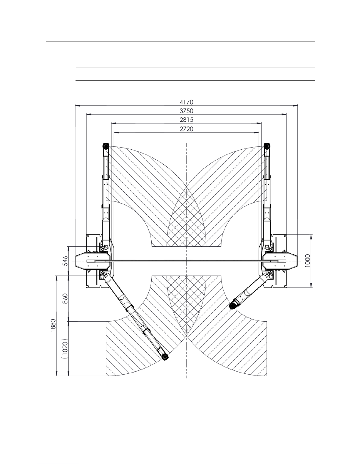
Pos: 35 /Technische Dokume ntation/ Hebet echnik/ 36 Säul en-Heb eb ühne n/1 601 E CON LI FT 6 500/ BA /Inh al t: 3 616 Tech nisc he Dat en ( Tab elle ) @ 45\ mod_1476255752058_75.docx @ 2589848 @ @ 1
Fuse (time-delay) 35 A
Motor power per column 4 kW
Working temperature range 5…40 °C
Extension range of support arms max…min. 1880…860 mm
Concrete grade C 20/25
Drive-through width 2720 mm
Net weight/Shipping weight approx. 1430/1530 kg
Overall width 3750 mm
Overall width including motor cover 4170 mm
Overall height 5185 mm
Bottom clearance of support arms 160 mm
Lifting height max. 2110 mm
Full travel 1900 mm
Inside base plates 2815 mm
Noise emission < 70 dB(A)
Inside columns 3000 mm
Supply frequency 50 Hz
Supply voltage 400 V
Column height 2966 mm
Outside columns 3560 mm
Page 10
10
BA361601-en
Load capacity 6500 kg
Adjustment range of support discs max…min. 175…130 mm
Pos: 36 /Techn ische Dokument ation/ Hebetech nik/3 6 Säul en-Heb ebühne n/1601 ECONLIFT 6500/ BA/Inh alt: 3616 Tec hnisc he Daten Dr aufsicht ( Bild) @ 45\mod_1476193659682_0.docx @ 2589363 @ @ 1
Pos: 37 /-----For ma t-----/MAN UE LLE R UM BR UCH Se iten umb ru ch @ 0\m od_1134403577687_0.docx @ 1277 @ @ 1
Page 11

11
BA361601-en
Pos: 38 /Technische Dokume ntation/ Hebet echnik/ 36 Säul en-Heb ebüh nen/ 1601 E CONLI FT 6500/ BA/ Inhal t: 3 616 Techn ische Date n Fr ontans icht (B ild) @ 45\mod_1476193488473_0.docx @ 2589316 @ @ 1
Pos: 39 /-----Form at-----/ MAN UE LLE R UM BR UCH Se iten umb ruc h @ 0\mod_1134403577687_0.docx @ 1277 @ @ 1
Page 12

12
BA361601-en
Pos: 40 /Technische Dokume ntation/ Alle Ger äte/Üb ersc hriften/ Überschr iften 1/T/Üb erschri ft 1: Tr anspor t und Lageru ng @ 2 0\mod_1268732488860_75.docx @ 826153 @ 1 @ 1
3
Transport and Storage
Pos: 41 /Technische Dokumentat ion/Alle Gerät e/Inhalte/I nhalt: Transp ort und Lagerung _12pt @ 26\mod_1324468980166_75.docx @ 1141285 @ @ 1
Check package to ensure it is complete, in accordance with the order
confirmation. Report any transport damage to the carrier immediately.
During loading, unloading and transport always use suitable lifting equipment,
material handling equipment (e.g. cranes, forklifts, etc.) and the right load handling
attachments and slings. Always ensure that the parts to be transported are
suspended or loaded properly so that they cannot fall, taking into account size,
weight and the centre of gravity.
Store the packages in a covered area, protected from direct sunlight, at a low
humidity and with temperatures between 0...+40 °C (32…104 °F). Do not stack
packages.
When unpacking, take care to avoid any possibility of injury or damage. Keep at a
safe distance when opening the package strapping, do not allow any parts to fall
out.
Pos: 42 /Tec hn isch e Dokum entat ion/Al le Gerät e/Übers chrift en/Über schrifte n 1/M /Übersc hrift 1 : Mont age und Erst inbetrieb nahm e @ 18\mod_1255417443299_75.docx @ 463797 @ 1 @ 1
4
Installation and Initial Operation
Pos: 43 /Technische Dokume ntation/ Alle Ger äte/I nhalte/I nhalt: M onta ge u nd Er stinbe trieb nahm e_12p t @ 26\mod_1324468562877_75.docx @ 1141153 @ @ 1
Installation and initial operation of the equipment may be done only by authorized
and trained service technicians provided by the manufacturer, licensed dealers or
service partners.
Pos: 44 /Technische Dokumentat ion/Alle Gerät e/Übersc hriften/Über schriften 1/B/ Überschri ft 1: Bedienung @ 6\mod_1174482271218_75.docx @ 76877 @ 1 @ 1
5
Operation
Pos: 45 /Technische Dokumentat ion/Alle Gerät e/Übersc hriften/Über schriften 1. 1/H/Überschr ift 1 .1: Haup tschal ter @ 6\mod _117 75928 58312_ 75.d ocx @ 90 635 @ 2 @ 1
5.1
Main Switch
Pos: 46 /Technische Dokume ntation/ Hebet echnik/ 00 HBZ Alle/In halte/In halt: H auptsch alter m it N ot-Aus- Funkt ion HBZ_1 2pt @ 26\mod_1325575201603_75.docx @ 1144333 @ @ 1
The main switch is used as emergency switch. In case of emergency turn it to
position 0.
• Main switch in position 0: Power supply is interrupted
• Main switch in position 1: Lift is ready for operation
• When in position 0, the main switch can be protected against
tampering by means of a padlock.
Pos: 47 /-----For ma t-----/MAN UE LLE R UM BR UCH Se iten umb ru ch @ 0\mod_1134403577687_0.docx @ 1277 @ @ 1
Page 13

13
BA361601-en
Pos: 48 /Technische Dokumentat ion/Alle Gerät e/Übersc hriften/Über schriften 1. 1/B/Überschr ift 1.1: Bedien- u nd Anzeigeel emente @ 23\mod _12 96220 30144 3_75.d ocx @ 96 8107 @ 2 @ 1
5.2
Controls and Indicators
Pos: 49 /Technische Dokume ntation/ Hebet echnik/ 36 Säul en-Heb e büh nen/ 160 1 EC ONLI FT 65 00/ BA/I nhal t: 361 6 Bed iene in heit US HT 1 ( Bi ld) @ 46\ mod_1481536171399_0.docx @ 2798138 @ @ 1
Pos: 50 /Technische Dokume ntation/ Hebet echnik/ 36 Säul en-Heb ebüh nen/ 1601 E CONLI FT 65 00/BA/ Inhal t: 361 6 Bediene inhe it USHT 1 ( Text) @ 46\ mod_1481106900905_75.docx @ 2794544 @ @ 1
A
Text display
D
(non-functional)
B
Menu
E
Raise
C
Confirm
F
Lower
Pos: 51 /-----For ma t-----/MAN UE LLE R UM BR UCH Se iten umb ru ch @ 0\mod_1134403577687_0.docx @ 1277 @ @ 1
B C D E F
A
Page 14

14
BA361601-en
Pos: 52 /Technische Dokume ntation/ Alle Ger äte/Üb ersc hriften/ Überschr iften 1.1/T/ Überschr ift 1. 1: Texta nzeige @ 45\mod_1472453476497_75.docx @ 2556978 @ 2 @ 1
5.3
Text Display
Pos: 53 /Tec hn isch e Dokum entat ion/Heb etech nik/36 Sä ulen-Heb ebüh nen/0 001 Säu len-Heb ebühne n Alle/ Inhalte/ Inhalt: 3600 Texta nzeige U SHT 1 - Norma ler Betrieb @ 46\mod_1481530261305_75.docx @ 2797838 @ 3 @ 1
5.3.1
Normal Operation
Example texts
System status
Notes
[LIFT MODEL,
Version]
System self-test. An acoustic signal sounds.
H 875 mm
Lifting carriages are at rest. Lift
is ready for operation.
The mean value of the lifting
height of the carriages + A or +
B is displayed in millimetres.
H 925 mm
H 975 mm
…
Lifting carriages move upwards.
The period between the updates
of the text display is
approximately 1 s, which
corresponds to a change in
height of about 5 cm.
H 825 mm
H 775 mm
…
Lifting carriages move
downwards.
The period between the updates
of the text display is
approximately 1 s, which
corresponds to a change in
height of about 5 cm.
Emergency stop
Only with option “Second
operating unit“: The emergency
stop switch on the counter-post
has been pressed, the drive
motors are switched off.
The same acoustic signal
sounds as during the lowering
below the anti-squeeze
protectionheight. After turning
off the emergency switch the
control restarts.
Pos: 54 /-----For ma t-----/MAN UE LLE R UM BR UCH Se iten umb ru ch @ 0\mod_1134403577687_0.docx @ 1277 @ @ 1
Page 15

15
BA361601-en
Pos: 55 /Techn ische Dokument ation/ Hebetech nik/3 6 Säul en-Hebeb ühne n/0001 S äulen-H ebebü hnen All e/Inhal te/In halt: 3 600 Tex tanzeige USHT 1 - Ref erenzier ung (2 017-03-10 1 1:18 :09) @ 46\mod_1481530708938_75.docx @ 2797886 @ 3 @ 1
5.3.2
Referenzierung
Example texts
System status
Notes
Reference Run
Operating data does not contain
a valid lifting height; a reference
run is required.
Operator must move the lifting
carriage to the lower end
position and confirm using the
Acknowledge button. “H 0 mm“
appears on the text display. If
the lifting carriages are not in
lower end position, confirmation
and completion of referencing is
not possible.
Caution: During referencing
cycles the current lifting height is
unknown! This process must be
performed without load!
Reference Run DN
Reference run of the lifting
carriages downwards ("down").
Referencing is performed in the
lower end position.
Pos: 56 /Technische Dokume ntation/ Hebet echnik/ 36 Säul en-Heb ebühne n/0001 S äulen- Hebebü hnen All e/Inhal te/In halt: 3 600 Tex tanzei ge USH T 1 - Fehlermeld ungen mit S ervicebed arf: E 000.. .E199 @ 46\mod_1481531068940_75.docx @ 2797934 @ 3 @ 1
5.3.3
Error Messages with Service Requirement: E000…E199
Error codes in this range indicate errors during operation or control initialisation
which cannot be remedied by the operator. The control system tries to transfer
the machine into a safe state mode. Service required to make the lift ready for
operation again.
Example texts
System status
Notes
Error E101
Load nut failure at column +A. Contact service!
Error E102
Load nut failure at column +B. Contact service!
Error E105
Difference between carriages is
> 50 mm. Lift is transferred into
safe state mode.
Contact service!
Pos: 57 /-----For ma t-----/MAN UE LLE R UM BR UCH Se iten umb ru ch @ 0\mod_1134403577687_0.docx @ 1277 @ @ 1
Page 16

16
BA361601-en
Pos: 58 /Technische Dokume ntation/ Hebet echnik/ 36 Säul en-Heb ebühne n/0001 S äulen- Hebebü hnen All e/Inhal te/In halt: 3 600 Tex tanzeige USHT 1 - F ehlerm eldun gen: E 200... E299 @ 46\ mod_1481531980511_75.docx @ 2798030 @ 3 @ 1
5.3.4
Error Messages: E200…E299
Error codes in this range indicate errors during control operation which typically do
not reappear after the lift has been restarted.
Example texts
System status
Notes
Button Error
Several buttons of the control
panel were presumably pressed
simultaneously.
Lift is transferred into a safe
state mode. After releasing the
buttons and a waiting period of
3 s the control is reinitialised.
Voltage Error
The supply voltage of the
assembly (U
Target
= 24 V) is
outside the permissible range.
Switch off the lift and wait 15 s
before switching on again!
If an error reappears the powersupplyof the lift has to be
checked by a specialist.
blocked +A
blocked +B
blocked
The control has detected a
blockage.
Raise/lower lift to unblock
support arms!
If the reference to post + A or +
B is missing, then either both
lifting carriages are blocked or
the location of the blockage is
unknown.
sinking +A
sinking +B
sinking
The control has detected an
automatic lowering.
If cause unknown – call service!
If the reference to column + A or
+ B is missing, then both lifting
carriages will lower.
Error E203
Lifting carriage +A is in lower
end position, but control
indicates at least 15 mm lifting
height ai column +A.
Possible cause of error:
Metallic object may be blocking
the sensor in the lower end
position at column +A or +B.
Removing the object and
restarting the control triggers a
follow-up referencing. The lift
can be moved downwards only.
The follow-up referencing must
be performed without load!
Error E204
Lifting carriage +B is in lower
end position, but control
indicates at least 15 mm lifting
height ai column +B.
Pos: 59 /-----For ma t-----/MAN UE LLE R UM BR UCH Se iten umb ru ch @ 0\mod_1134403577687_0.docx @ 1277 @ @ 1
Page 17

17
BA361601-en
Pos: 60 /Tec hnische Do kument ation/Al le Gerät e/Übersc hriften/ Übers chrifte n 1.1/M/Üb ersc hrift 1.1: Me nüführu ng @ 46\mod_1479385748768_75.docx @ 2780926 @ 2 @ 1
5.4
Menu Navigation
Pos: 61 /Tec hn isch e Dokume ntation/ Alle Geräte/Über schriften/ Überschri ften 1.1.1/Ü/ Überschri ft 1.1.1: Übersich t @ 16\mod_1246353242165_75.docx @ 399194 @ 3 @ 1
5.4.1
Exploded View
Pos: 62 /Technische Dokume ntation/ Hebet echnik/ 36 Säul en-Heb ebüh nen/ 1601 E CONLI FT 6500/ BA/ Inhal t: 3616 Menü führun g USHT 1 (Übe rsicht) @ 4 6\mod_1481109443715_75.docx @ 2794642 @ @ 1
H 1234 mm
Operating mode/Rest mode
Menu
ECONLIFT MENU
Lower Raise
Automatic Stop
Confirm
Menu
120 mm
Preselection in
intervals of 10 mm
with Raise/Lower
Lower Raise
S/N Machine
Confirm
Menu
123456-001
Lower Raise
S/N ECU
Confirm
Menu
001-123456789000
Lower Raise
ECONLIFT MENU
Lower Raise
Automatic Stop
Pos: 63 /Tec hn isch e Dokum entat ion/Heb etech nik/36 Sä ulen-Heb eb ühne n/1 601 ECO NLI FT 6 500/ BA/Inh alt: 361 6 Menü führ ung USHT 1 (M enüpu nkt e) @ 46\mod_1481110149865_75.docx @ 2794689 @ 33333 @ 1
5.4.2
Preselecting the Automatic Stop
Lift in operating mode/rest mode.
1 Press “Menu” once, then press “Lower”, until menu item “Automatic Stop”
appears.
2 Press “Confirm”.
3 Preselect required lifting height using “Raise/Lower” in intervals of 10 mm.
NOTE: Minimum height of automatic stop is 120 mm.
4 Press “Menu” once to quit the preselection. Press “Menu” again to go back to
the operating mode.
5.4.3
Disabling the Automatic Stop
Lift in operating mode/rest mode.
1 Press “Menu” once, then press “Lower”, until menu item “Automatic Stop”
appears.
2 Press “Confirm”.
Page 18

18
BA361601-en
3 Use “Raise/Lower” to preselect a lifting height
below
the minimum height of the
automatic stop (120 mm) or
above
the maximum lifting height. Display “OFF”
appears.
4 Press “Menu” once to quit the preselection. Press “Menu” again to go back to
the operating mode.
5.4.4
Displaying the Serial Number of the Lift
Lift in operating mode/rest mode.
1 Press “Menu” once, then press “Lower”, until menu item “S/N Machine”
appears.
2 Press “Confirm”. Serial number is displayed.
3 Press “Menu” once to quit the preselection. Press “Menu” again to go back to
the operating mode.
5.4.5
Displaying the Serial Number of the Lift Control
Lift in operating mode/rest mode.
1 Press “Menu” once, then press “Lower”, until menu item “S/N ECU” appears.
2 Press “Confirm”. Serial number is displayed.
3 Press “Menu” once to quit the preselection. Press “Menu” again to go back to
the operating mode.
5.4.6
Displaying the Cloud ID
Lift in operating mode/rest mode.
1 Press “Menu” once, then press “Lower”, until menu item “Cloud ID” appears.
2 Press “Confirm”. Cloud ID is displayed.
3 Press “Menu” once to quit the preselection. Press “Menu” again to go back to
the operating mode.
Pos: 64 /-----For ma t-----/MAN UE LLE R UM BR UCH Se iten umb ru ch @ 0\mod_1134403577687_0.docx @ 1277 @ @ 1
Page 19

19
BA361601-en
Pos: 65 /Technische Dokume ntation/ Alle Ger äte/Übers chriften/ Überschrifte n 1.1/T/Über schrift 1.1: Tra garmarret ierung @ 9\mod_ 12101 6136 4709_ 75.d ocx @ 212 107 @ 2 @ 1
5.5
Arm Restraint
Pos: 66 /Technische Dokume ntation/ Hebet echnik/ 00 HBZ Alle/In halte/ Warnun g!/Inha lt: Warn ung - Arretier hebel_1 2pt @ 38\mod_1403765432254_75.docx @ 2044214 @ @ 1
Never unlatch the arm restraint while the lift is loaded.
Pos: 67 /Technische Dokume ntation/ Hebet echnik/ 36 Säul en-Heb eb ühne n/1 601 E CON LI FT 6 500/ BA /Inh al t: 3 616 Trag arm arr etier un g ( Bild ) @ 38\mod_1403766582198_0.docx @ 2044306 @ @ 1
Pos: 68 /Technische Dokume ntation/ Hebet echnik/ 36 Säul en-Heb eb ühne n/1 601 E CON LI FT 6 500/ BA /Inh al t: 3 616 Trag arm arr etier un g ( Text) @ 3 8\mod_1403765565010_75.docx @ 2044260 @ @ 1
Each support arm is provided with an arm restraint which unlocks automatically
when the lift reaches bottom position.
When the carriages are in a raised position, the arm restraint can be disengaged
by pulling the restraint pin. Once the restraint pin is released, the arm restraint
locks automatically.
Pos: 69 /-----For ma t-----/MAN UE LLE R UM BR UCH Se iten umb ru ch @ 0\mod_1134403577687_0.docx @ 1277 @ @ 1
Page 20

20
BA361601-en
Pos: 70 /Technische Dokume ntation/ Alle Ger äte/Üb ersc hriften/ Überschr iften 1.1/V/ Übersc hrift 1 .1: Vorber eit ungen @ 8\mod_1204639543920_75.docx @ 155816 @ 2 @ 1
5.6
Preparations
Pos: 71 /Technische Dokume ntation/ Hebet echnik/ 36 Säul en-Heb ebühne n/0001 S äulen- Hebebü hnen All e/Inhal te/In halt: Vor bereitu ngen S äulen-H BZ_1 2pt @ 26\mod_1326281605536_75.docx @ 1152171 @ @ 1
1 Fully lower the lift and swing the arms to full drive-through position.
2 Slowly position the vehicle midway between adapters. Apply the parking brake.
3 Swing and telescope arms as required to position adapters under vehicle
manufacturer's recommended lift points.
4 Turn the disc adapters in such a way that they evenly contact all four lift points.
5 Leave vehicle and remain clear of lift.
Pos: 72 /Technische Dokume ntation/ Hebet echnik/ 36 Säul en-Heb eb ühne n/2 601 E CON II I/BA /In ha lt: 3626 Auf nahme teller -Erh öhu ng ( Tex t) @ 27\mod_1328091030599_75.docx @ 1536647 @ @ 1
Extenders
The disk adapters can be raised in steps of 50 mm by using extenders. For fine
adjustment turn the disk adapters as required.
The extenders are optionally available in heights of 50, 100, 150 and 200 mm.
Use
ONE
extender only for each disk adapter.
Make sure the spring dowel sleeves lock into place.
Pos: 73 /Technische Dokume ntation/ Hebet echnik/ 36 Säul en-Heb ebüh nen/ 2601 E CON I II/ BA/In halt : 36 26 Au fnahm etel ler-Erhöhung (Bilder) @ 11\mod_1230030932822_0.docx @ 288858 @ @ 1
Pos: 74 /-----For ma t-----/MAN UE LLE R UM BR UCH Se iten umb ru ch @ 0\mod_1134403577687_0.docx @ 1277 @ @ 1
Page 21

21
BA361601-en
Pos: 75 /Technische Dokume ntation/ Hebet echnik/ 36 Säul en-Hebebühnen/1601 ECONLIFT 6500/BA/Inhalt: 3616 Warnung - Mindestabstand ei nhalten @ 38\mod_1403773903537_75.docx @ 2044552 @ @ 1
Allow for a minimum distance of 700 mm between adapters.
Pos: 76 /Technische Dokume ntation/ Hebet echnik/ 36 Säul en-Hebebühnen/1601 ECONLIFT 6500/BA/Inhalt: 3616 Info - Leichte Positionierung der Tragarme @ 38\mod _1 403 775 3566 58_ 75.d ocx @ 2 044 691 @ @ 1
Lifts with option "double telescopic swing arms" are
supplied with a positioning rod (1) and a tube section (2) at
the tip of the arm extensions.
Insert the rod in the tube section and draw out the arm
extensions to position adapters under vehicle
manufacturer's recommended lift points.
When not in use hang the rod on one of the holders (3)
provided at the columns.
Pos: 77 /-----For ma t-----/MAN UE LLE R UM BR UCH Se iten umb ru ch @ 0\mod_1134403577687_0.docx @ 1277 @ @ 1
Page 22

22
BA361601-en
Pos: 78 /Technische Dokume ntation/ Papier korb/Üb erschr iften/Ver sionier t/Über schr ift 1.1: He be n @ 1 1\mod_1231312451376_75.docx @ 288900 @ 2 @ 1
5.7
Raising
Pos: 79 /Technische Dokume ntation/ Hebet echnik/ 00 HBZ Alle/In halte/ Warnun g!/Inha lt: Warn ung - Tragarm arretier ung Säu len-H BZ_ 12p t @ 2 6\mod_1326708509854_75.docx @ 1506469 @ @ 1
• Once the disk adapters contact the lift points, check arm restraints for secure
engagement.
• If necessary, slightly move the arms until the gear segments mesh.
• Never pull the restraint pins when the lift is under load!
Pos: 80 /Tec hn isch e Dokum entat ion/Heb etech nik/36 Sä ulen-He b ebüh ne n/400 1 MA PO WER II 3.0/ 3.5/ BA/ Inha l t: 36 40 H ebe n @ 29\mod_1351148950012_75.docx @ 1668782 @ @ 1
1 Turn the main switch to position 1.
2 Push and hold RAISE button until lift reaches desired height.
Pos: 81 /Technische Dokume ntation/ Hebet echnik/ 36 Säul en-Heb eb ühne n/4 301 M A POWE R II ML 2C-E/ BA /Inha l t: 36 43 | 36 44 In fo - 1 sec War teze it zum näc hst en H ub-/Se nkvor gang @ 46\mod_1481278206915_75.docx @ 2797009 @ @ 1
After the “Raise” or “Lower” button has been pressed, a waiting period of at least
1 second must elapse before the next raising or lowering operation can be
performed.
Pos: 82 /Technische Dokumentat ion/Alle Gerät e/Übersc hriften/Über schriften 1. 1/A/Übersc hrift 1.1: Arbeite n am angehob enen Fahr zeug @ 11\mod_1231313188263_75.docx @ 288992 @ 2 @ 1
5.8
Vehicle in Raised Position
Pos: 83 /Technische Dokume ntation/ Hebet echnik/ 36 Säul en-Heb eb ühne n/260 1 ECON III /BA/I nha lt: 3626 Ar bei ten am an gehobe nen F ahrz eug @ 2 7\mod_1328091238302_75.docx @ 1536779 @ @ 1
• Observe all applicable accident prevention regulations.
• Do not allow unauthorized persons to stay under the raised vehicle.
• Avoid rocking of vehicle.
• Keep the support arms and the vehicle free of tools and parts.
Use caution when removing or installing heavy
components. The vehicle may be tilted off the lift due to
center-of-gravity displacement.
Fasten the vehicle to the support arms using lashing
straps.
Pos: 84 /Technische Dokumentat ion/Alle Gerät e/Übersc hriften/Über schriften 1. 1/S/Übersc hrift 1.1: Senken @ 6\mod_1180960432671_75.docx @ 95086 @ 2 @ 1
5.9
Lowering
Pos: 85 /Technische Dokume ntation/ Hebet echnik/ 36 Säul en-Heb ebüh nen/4 001 M AP OWE R II 3. 0/3. 5/B A/In hal t: 36 40 S enk en @ 2 9\mod_1351149234612_75.docx @ 1668826 @ @ 1
1 Remove tools, stands or other objects from lift bay.
3 Push and hold LOWER button until lift reaches desired height.
3 To lower the arms completely after reaching the CE stop position (pinch point
protection), release the LOWER button and push it again.
4 Swing the arms to full drive-through position and drive the vehicle off the lift.
Pos: 86 /-----For ma t-----/MAN UE LLE R UM BR UCH Se iten umb ru ch @ 0\m od_1134403577687_0.docx @ 1277 @ @ 1
Page 23

23
BA361601-en
Pos: 87 /Technische Dokume ntation/ Alle Ger äte/Üb ersc hriften/ Überschr iften 1.1/M/ Übersc hrift 1 .1: Ma nuelles Ab senke n @ 6\mod_1178113285703_75.docx @ 90869 @ 2 @ 1
5.10
Manual Lowering
Pos: 88 /Tec hn isch e Dokum entat ion/Heb etech nik/36 Sä ulen-Hebebühnen/1601 ECONLIFT 6500/BA/Inhalt: 3616 Manuelles Absenken Teil 1 (Text) @ 38\mod_1403780996534_75.docx @ 2044849 @ @ 1
In case of defect or power failure the lift can be lowered manually.
• Authorised personnel only!
• Do not restart the lift before the error has been remedied!
• The lift may only be lowered, not raised.
Pos: 89 /Technische Dokume ntation/ Hebet echnik/ 36 Säul en-Heb ebüh nen/ 1601 E CONLI FT 6500/ BA/ Inhal t: 3 616 Ma nuel les Absenk en (Bild ) @ 38\mod_1403781400160_0.docx @ 2045035 @ @ 1
Pos: 90 /Technische Dokume ntation/ Hebet echnik/ 36 Säul en-Hebebühnen/1601 ECONLIFT 6500/BA/Inhalt: 3616 Manuelles Absenken Teil 2 (Text) @ 46\mod_1481284547812_75.docx @ 2797385 @ @ 1
• Remove the cover hoods from both motors to make the pulleys accessible.
• Using a wrench, lower both carriages in increments of 20 mm by intermittently
turning the lifting screws.
• After lowering the lift reinstall the cover hoods.
Pos: 91 /-----For ma t-----/MAN UE LLE R UM BR UCH Se iten umb ru ch @ 0\mod_1134403577687_0.docx @ 1277 @ @ 1
Page 24

24
BA361601-en
Pos: 92 /Technische Dokumentat ion/Alle Gerät e/Übersc hriften/Über schriften 1/I /Überschr ift 1: Instandhalt ung @ 28\mod_ 1332 15981 2536_ 75.doc x @ 1565 908 @ 1 @ 1
6
Maintenance
Pos: 93 /Technisch e Dokum entat ion/Al le Gerät e/Inhal te/War nung!/In halt: W arnu ng - Ha uptscha lter aus bei I nstandh altung_ 12pt @ 26\mod_1324465229892_75.docx @ 1140563 @ @ 1
Danger! Electric shock hazard!
Before doing any maintenance work, turn off the main switch and protect it
against tampering.
Pos: 94 /Technische Dokume ntation/ Alle Ger äte/Üb ersc hriften/ Überschr iften 1.1/J/Üb ersc hrift 1.1 : Jähr liche Überpr üfung @ 28\mod_1332230089694_75.docx @ 1566204 @ 2 @ 1
6.1
Annual Inspection
Pos: 95 /Techn ische Dokume ntation/Al le Geräte/Inh alte/Info!/I nhalt: Info - Jähr liche Über prüfu ng_12pt @ 2 5\mod_1324460481075_75.docx @ 1139412 @ @ 1
• The maintenance interval prescribed by the manufacturer is
12 (twelve) months
.
This maintenance interval refers to normal workshop usage. If the equipment is
used more frequently or under severe operating conditions (e.g. outdoors), the
interval must be reduced accordingly.
• Maintenance work shall be done only by authorized and trained service
technicians provided by the manufacturer, licensed dealers or service partners.
• In case of non-compliance the manufacturer's warranty becomes void.
Pos: 96 /Technische Dokume ntation/ Hebet echnik/ 00 HBZ Alle/In halte/Inf o!/In halt: I nfo - DG UV Re gel 100- 500 / DG UV G ru ndsatz 308-003_12pt @ 47\mod_1483611185270_75.docx @ 2804763 @ @ 1
Pos: 97 /-----For ma t-----/MAN UE LLE R UM BR UCH Se iten umb ru ch @ 0\mod_1134403577687_0.docx @ 1277 @ @ 1
Page 25

25
BA361601-en
Pos: 98 /Technische Dokumentat ion/Alle Gerät e/Übersc hriften/Über schriften 1. 1/I/Übersc hrift 1.1: Ins tand haltu ngsp lan @ 11\mod_1231318919401_75.docx @ 289622 @ 2 @ 1
6.2
Maintenance Schedule
Pos: 99 /Technische Dokume ntation/ Hebet echnik/ 36 Säul en-Heb ebüh nen/ 1601 E CONLI FT 6500/ BA/ Inhal t: 3 616 Ins ta ndhalt ungsp lan @ 38\mod_1404890255642_75.docx @ 2052764 @ @ 1
Interval
Maintenance points
Procedure
1 week Supports
Check for function.
Check for wear, replace as required.
3 months Lifting screws
Check oil level in oil sumps, top up if
required.
6 months
Load nuts
Check for smooth operation, lubricate
as required.
Slide tracks
Support arm extensions
Support discs
12 months
Upper support of lifting
screws
Lubricate using a grease gun.
Screw brake
Check brake blocks for wear, replace
as required.
Load nuts Check for wear.
Drive system of lift
Check drive belts for wear, dirt and
correct tension.
General inspection Check all components for damage.
Pos: 100 /Technische D okumen tation/ Alle G eräte/ Überschr iften/ Übers chrifte n 1.1/P/ Überschr ift 1 .1: Pf legeh inwe ise @ 15\m od_1245912234854_75.docx @ 395780 @ 2 @ 1
6.3
Care Instructions
Pos: 101 /Tech nische Dok umen tati on/All e G eräte/I nha lte/I nhalt : Pfle gehi nwe ise - A lle Geräte_1 2pt @ 26\mod_1324468886116_75.docx @ 1141252 @ @ 1
• Periodically clean the equipment and treat it with a care product.
• Repair damage to the paintwork immediately to prevent corrosion.
• Usage of caustic cleaning agents or high pressure and steam jet cleaners may
lead to equipment damage.
Pos: 102 /Technische D okumen tation/ Alle G eräte/In halt e/I nfo!/I nhalt : Inf o - Pf lege hinwe ise_12p t @ 26\mod_1324461215655_75.docx @ 1139602 @ @ 1
Regular care and maintenance is the key condition for functionality and long life
expectancy of the equipment!
Pos: 103 /-----F orma t-----/M ANUE LLER UM BRUC H Seitenum bru ch @ 0\mod_1134403577687_0.docx @ 1277 @ @ 1
Page 26

26
BA361601-en
Pos: 104 /Technische D okumen tation/ Alle G eräte/ Überschr iften/ Übers chrifte n 1.1/SCH /Über schrif t 1.1: Schmieru ng @ 34\mod_1379919006147_75.docx @ 1830969 @ 2 @ 1
6.4
Lubrication
Pos: 105 /Te chn isch e D okumen tation/All e Geräte/Über schriften/Üb erschrif ten 1.1.1/SCH/ Überschrif t 1.1.1: Schmierm ittel @ 34\mod_1379919730255_75.docx @ 1831057 @ 3 @ 1
6.4.1
Lubricants
Pos: 106 /Te chn isch e D okum en tati on/H ebe te chnik /36 Säu le n-Heb ebü hne n/ 160 1 ECO NLIF T 6 500/ BA/ Inh alt : 36 16 S chm ie rmit te l @ 4 6\mod_1481285701682_75.docx @ 2797437 @ @ 1
Lubricating points
Lubricants
Lifting screw/Load nut
Gear oil of viscosity class
SAE 140
(Part # 36 1100 0)
IMPORTANT: Safe and reliable operation cannot
be guaranteed if other lubricants are used!
Upper support of lifting screw
Support arm extensions
Threads of support discs
G-Oil Fago EP2
(previously named: Q8 Rembrandt EP2)
Pos: 107 /Te chn isch e D okum en tati on/All e Geräte/ Über schrifte n/Über schrif ten 1.1 .1/H/Üb erschrif t 1. 1.1: Hub spinde lschmier ung @ 38\mod_1403853164770_75.docx @ 2045614 @ 3 @ 1
6.4.2
Lifting Screw Lubrication
Pos: 108 /Te chn isch e D okum en tati on/H ebe te chnik /36 Säu le n-Hebebü hnen/ 1601 E CONLI FT 650 0/BA/I nhalt : 3616 Info - Schm ierun g der Hubs pind el @ 38\m od_ 140 385 340 034 7_75. doc x @ 204 566 0 @ @ 1
Use gear oil that meets SAE 140 specifications for lubricating the lifting screw.
Pos: 109 /Te chn isch e D okum en tati on/H ebe te chnik /36 Säu len -Hebeb ühn en/ 1601 EC ONLI FT 6500/ BA/I nhalt : 36 16 Hub spi ndels chm ierung (Bild er) @ 38\m od_1403854207871_0.docx @ 2045752 @ @ 1
Pos: 110 /Te chn isch e D okum en tati on/H ebe te chnik /36 Säu le n-Heb ebü hne n/ 160 1 ECO NLIF T 6 500/ BA/I nha lt : 36 16 H ubspind elschm ierung (Text) @ 38\mod_1403853519556_75.docx @ 2045706 @ @ 1
Quarterly check the oil level in the lifting screw reservoir and refill as required (see
below). Minimum oil level is 5 mm.
The reservoir is located at the carriage, behind the lifting screw cover.
Pos: 111 /-----F orma t-----/M ANUELLE R UMBR UCH Seitenum bruc h @ 0\mod_1134403577687_0.docx @ 1277 @ @ 1
min. 5mm
Page 27

27
BA361601-en
Pos: 112 /Technische D okumen tation/ Alle G eräte/ Überschr iften/ Übers chrifte n 1.1.1/O/ Über schrift 1.1.1: Obere H ubsp indell agerun g @ 38\mod_1403857353736_75.docx @ 2046124 @ 3 @ 1
6.4.3
Upper Support of Lifting Screw
Pos: 113 /Te chn isch e D okum en tati on/H ebe te chnik /36 Säu le n-Heb ebü hne n/ 160 1 ECO NLIF T 6 500/ BA/I nha lt : 36 16 O ber e H ubsp inde lla ger ung ( Tex t) @ 38\ mod_1403857403622_75.docx @ 2046170 @ @ 1
Once a year grease the upper supports of the lifting screw sing a grease gun. The
lubricator nipple is accessible through a hole in the upper part of the column
cover.
Pos: 114 /Te chn isch e D okum en tati on/H ebe te chnik /36 Säu le n-Hebebü hne n/ 160 1 ECO NLIF T 6 500/ BA/I nha lt : 36 16 O ber e H ubsp inde lla ger ung ( Bi ld) @ 38\ mod_1403857505143_0.docx @ 2046216 @ @ 1
Pos: 115 /Technische D okumen tation/ Alle G eräte/ Überschr iften/ Übers chrifte n 1.1.1/ T/Übersc hrif t 1.1.1: Tragar mauszü ge schm iere n @ 11\mod_1231396065647_75.docx @ 299631 @ 3 @ 1
6.4.4
Greasing the Arm Extensions
Pos: 116 /Te chn isch e D okum en tati on/H ebe te chnik /36 Säu le n-Heb ebü hne n/ 260 1 ECO N II I/BA /In hal t: 3 626 Tra garm ausz üg e sc hmi er en EC ON I II 3.0/ 3.5/ 4. 0/5. 0 ( Tex t) @ 27\m od_1 328097565265_75.docx @ 1537591 @ @ 1
1 Every six months check the support arm extensions for smooth operation.
2 Grease as required.
Pos: 117 /Te chn isch e D okum en tati on/H ebe te chnik /36 Säu le n-Heb ebü hne n/ 160 1 ECO NLIF T 6 500/ BA/I nha lt : 36 16 Tr aga rma uszüge s chm ieren (B ild) @ 38\mod _14 03857 7614 15_0.d ocx @ 204 6312 @ @ 1
Pos: 118 /Technische D okumen tation/ Alle G eräte/ Überschr iften/ Übers chrifte n 1.1.1/G/ Über schrift 1.1.1: Gewinde der Aufna hmete ller schm ieren @ 11\mod_1231397117832_75.docx @ 299766 @ 3 @ 1
6.4.5
Greasing the Disc Adapter Threads
Pos: 119 /Te chn isch e D okum en tati on/H ebe te chnik /36 Säu le n-Hebebü hnen/ 2601 E CON II I/BA/In halt: 3 626 Gew inde d er Auf nahmet eller sc hmier en (Tex t) @ 27\mod_1328097630220_75.docx @ 1537635 @ @ 1
1 Every six months check the threads of the disc adapters for smooth operation.
2 Grease as required.
Pos: 120 /Te chn isch e D okum en tati on/H ebe te chnik /36 Säu le n-Hebebü hnen/ 2601 E CON II I/BA/In halt: 3 626 Gew inde d er Auf nahmet eller sc hmier en (B ild) @ 11\mod _1231 39725 9636_ 0.d ocx @ 299 811 @ @ 1
Pos: 121 /-----F orma t-----/M ANUELLE R UMBR UCH Seitenum bruc h @ 0\mod_1134403577687_0.docx @ 1277 @ @ 1
Page 28

28
BA361601-en
Pos: 122 /Te chn isch e D okume nta tion/A lle G eräte/ Üb erschr ifte n/Üb ersc hrifte n 1.1/ F/ Übersc hrift 1.1 : Fun ktio ns- und Verschl eißkontr ollen @ 29\m od_1 35106 99105 94_ 75.docx @ 1667 179 @ 2 @ 1
6.5
Operational and Wear Checks
Pos: 123 /Technische D okumen tation/ Alle G eräte/ Überschr iften/ Übers chriften 1.1.1/ T/Überschr ift 1.1.1: Tragm utterversch leiß @ 38\mod_1403854694159_75.docx @ 2045798 @ 3 @ 1
6.5.1
Load Nut Wear Check
Pos: 124 /Te chn isch e D okum en tati on/H ebe te chnik /36 Säu le n-Heb ebü hne n/ 160 1 ECO NLIF T 6 500/ BA/I nha lt : 36 16 Tr agm utt er ver schleiß ( Text) @ 38\mod_1403854905585_75.docx @ 2045844 @ @ 1
Once a year check the load nuts for wear.
If load nut wear has been found, shut down and lock the lift until the load nut has
been replaced.
• Raise the lift to approx. midpoint of travel and remove the plastic cap (3) from
the column cover.
• Raise or lower the lift until the inspection window in the carriage (1) lines up with
the window in the column cover (2).
Pos: 125 /Te chn isch e D okum en tati on/H ebe te chnik /36 Säu le n-Hebebü hnen/ 1601 ECON LIF T 6 500/ BA/I nha lt: 36 16 Tra gm utt erv ers chlei ß ( Bild er) @ 3 8\mod_1403855146429_0.docx @ 2045890 @ @ 1
Pos: 126 /Te chn isch e D okum en tati on/H ebe te chnik /36 Säu le n-Hebebühnen/1601 ECONLIFT 6500/BA/Inhalt: 3616 Verschleißkontrolle (Text) @ 38\mod_1403855413093_75.docx @ 2045936 @ @ 1
Wear Check
The check screw now becomes visible in the inspection window.
A clearance of approx. 2 mm between check screw (1) and safety nut (2) is preset
at the factory.
If no clearance can be detected, have the load nut replaced prior to further use.
At completion of load nut wear check reinstall the plastic caps.
Pos: 127 /-----F orma t-----/M ANUELLE R UMBR UCH Seitenum bruc h @ 0\mod_1134403577687_0.docx @ 1277 @ @ 1
Page 29

29
BA361601-en
Pos: 128 /Te chn isch e D okum en tati on/All e Ger äte/Über schr iften/Üb erschrif ten 1.1 .1/G/ Überschr ift 1. 1.1: Gumm iaufla gen der Auf nahmete ller pr üfen @ 29\mod_1351070879871_75.docx @ 1667311 @ 3 @ 1
6.5.2
Checking the Rubber Pads of the Support Discs
Pos: 129 /Te chn isch e D okum en tati on/H ebe te chnik /36 Säu len -Hebebü hnen/ 4001 MAP OWER II 3.0/ 3.5/BA/ Inha lt: 36 40 Gumm iauflage n der Aufnahm etel ler (Text) @ 2 9\mod_1351071304640_75.docx @ 1667355 @ @ 1
1 Weekly check the rubber pads for wear.
2 Replace defective pads.
Pos: 130 /Technische D okumen tation/ Alle G eräte/ Überschr iften/ Übers chrifte n 1.1.1/S/ Über schrift 1.1.1: Spind elbremse prüfe n @ 38\mod_1403858149908_75.docx @ 2046358 @ 3 @ 1
6.5.3
Checking the Brakes of the Lifting Screws
Pos: 131 /Te chn isch e Dok umen tation/Heb ete chnik/ 36 Säule n-Heb ebü hne n/16 01 E CO NLIF T 6 500/ BA/I nha lt : 36 16 I nfo - Kontak tflächen fettfr ei @ 38\mod_1403858261112_75.docx @ 2046454 @ @ 1
Make sure the contact surface between brake block and pulley is free of
lubricants.
Pos: 132 /Te chn isch e D okum en tati on/H ebe te chnik /36 Säu le n-Hebeb ühn en/ 1601 E CON LIFT 6500/ BA/I nhalt : 36 16 Sp indelb rems e p rüfe n (Bi ld) @ 38\mod_1403858401681_0.docx @ 2046500 @ @ 1
Pos: 133 /Te chn isch e D okum en tati on/H ebe te chnik /36 Säu len -Hebe bü hnen/ 16 01 E CON LIF T 6 500/ BA/I nha lt : 36 16 Sp ind elbr ems e p rüfe n ( Text) @ 46\mod_1481286599000_75.docx @ 2797484 @ @ 1
Once annually check the brake blocks for wear and replace them as required.
The wear limit is marked by a groove in the brake block.
Pos: 134 /Technische D okumen tation/ Alle G eräte/ Überschr iften/ Übers chrifte n 1.1.1/A/ Über schrift 1.1.1: Antriebs riem en pr üfen @ 46\mod_1481286761257_75.docx @ 2797531 @ 3 @ 1
6.5.4
Checking the Drive Belt
Pos: 135 /Te chn isch e D okum en tati on/H ebe te chnik / 36 Säu le n-Heb ebü hn en/ 160 1 ECO NLI FT 650 0/BA/ I nhalt : 36 16 A ntr iebs ri emen pr üfe n @ 46\m od_1 481 286 8410 41_ 75.d ocx @ 279 757 9 @ @ 1
Once a year check the drive belts for wear, dirt and correct tension. Worn-out
belts must be replaced. Make sure the running surface is free from lubricants.
Pos: 136 /-----F orma t-----/M ANUELLE R UMBR UCH Seitenum bruc h @ 0\mod_1134403577687_0.docx @ 1277 @ @ 1
Page 30

30
BA361601-en
Pos: 137 /Technische D okumen tation/ Alle G eräte/ Überschr iften/ Übers chrifte n 1.1.1/SC H/ Überschrif t 1. 1.1: Sch utzscha lter p rüfen @ 46\mod_1481279722477_75.docx @ 2797196 @ 3 @ 1
6.5.5
Checking the Circuit Breaker
Pos: 138 /Te chn isch e D okum en tati on/H ebe te chnik /36 Säu le n-Heb ebü hne n/ 160 1 ECO NLIF T 6 500/ BA/I nha lt : 36 16 Sc hu tzsc hal ter prüf en @ 46\mod_1481280836198_75.docx @ 2797244 @ @ 1
A shockproof socket that can be accessed from the outside is installed to the side
wall of the control box. The function of the related FI/CB switch (-F2) inside the
control box must be tested by an authorised person.
To test the function, press the test button “T” while in operation; the FI/CB switch
must trigger immediately. The function check shall be carried out on a regular
basis, but at least every six months unless other regional or user-specific
additional tests are planned.
In addition to the functional test of the circuit breaker, the effectiveness of the
protective measures in the installation must be checked in accordance with the
applicable regulations.
Pos: 139 /Te chn isch e D okum en tati on/All e Ger äte/Über schr iften/Üb erschrif ten 1.1/E /Üb erschrif t 1.1: Er satzte ile @ 18\mod_1255596847002_75.docx @ 474414 @ 2 @ 1
6.6
Spare Parts
Pos: 140 /Technische D okumen tation/ Alle G eräte/In halt e/Inhalt : Ersatz teile - A lle G eräte_1 2pt @ 26\mod_1324468768120_75.docx @ 1141219 @ @ 1
To ensure safe and reliable operation, only use original spare parts supplied by the
equipment manufacturer.
Pos: 141 /-----F orma t-----/M ANUELLE R UMBR UCH Seitenum bruc h @ 0\mod_1134403577687_0.docx @ 1277 @ @ 1
Page 31

31
BA361601-en
Pos: 142 /Technische D okumen tation/ Alle G eräte/ Überschr iften/ Übers chrifte n 1/L/Über schr ift 1: Lebens dauer @ 19\m od_12 66336 76155 0_7 5.docx @ 74242 3 @ 1 @ 1
7
Service Lifetime
Pos: 143 /Te chn isch e D okum en tati on/H ebe te chnik /00 H BZ All e/Inhal te/Inhal t: Lebe nsdau er HBZ_ 12pt @ 26\mod_1325656335645_75.docx @ 1146173 @ @ 1
In its standard version, this product is designed for 22,000 load cycles based on
EN 1493. The maximum period of normal use in relation to the possible product
life expectancy shall be evaluated and scheduled by a qualified person during the
annual safety inspection.
Pos: 144 /Technische D okumen tation/ Alle G eräte/ Überschr iften/ Übers chrifte n 1/D/Üb erschr ift 1: Demon tage @ 19\mod _12 66336 8228 63_75.d ocx @ 74 2452 @ 1 @ 1
8
Dismantling
Pos: 145 /Technische D okumen tation/ Alle G eräte/In halt e/Inhalt : Dem ontage - Alle Ger äte_ 12p t @ 26\mod_1324466078229_75.docx @ 1140857 @ @ 1
Decommissioning and dismantling of the equipment may be done only by
specially authorized and trained personnel provided by the manufacturer, licensed
dealers or service partners.
Pos: 146 /Technische D okumen tation/ Alle G eräte/ Überschr iften/ Übers chrifte n 1/G/ Überschr ift 1: G erätee ntsorg ung @ 6\mod_1174482271625_75.docx @ 76901 @ 1 @ 1
9
Disposal
Pos: 147 /Tech nische Dokumen tati on/Alle G eräte/I nhalt e/Inhalt : Ger äteentsor gung d urch Betreiber allg_ 12pt @ 26\mod_1324467874153_75.docx @ 1140955 @ @ 1
Pay attention to the product and safety data sheets of the lubricant used. Avoid
damage to the environment. Should a disposal of the device be necessary it must
be done in adherence with locally applicable legal regulations regarding
environmental protection. Remove all materials properly sorted out and bring them
to a suitable waste disposal service. Collect operating materials such as grease,
oils, coolant, solvent-based cleaning fluids etc. in suitable containers and dispose
of in an environmentally protective manner.
Pos: 148 /Technische D okumen tation/ Alle G eräte/In halt e/Inhalt : Geräte entsor gung über F achbetri eb (a lter na tiv )_1 2pt @ 2 6\mod_1324468120852_75.docx @ 1141022 @ @ 1
Alternatively, you may take the equipment to a specialised waste management
plant to ensure that all components and operating liquids are properly disposed
of.
Pos: 149 /Te chn isch e D okum enta tion/A lle Ger äte/Über schr iften/Üb erschrif ten 1/I/ Über schrift 1: Inh alt der K onform itätser klärun g @ 22\mod_1292856748432_75.docx @ 958616 @ 1 @ 1
10
Contents of the Declaration of Conformity
Pos: 150 /Technische D okumen tation/ Alle G eräte/In halt e/Inhalt : Inh alt der Konf or mit äts erklär u ng a llg_ 12pt @ 2 6\mod_1324468436145_75.docx @ 1141120 @ @ 1
MAHA Maschinenbau Haldenwang GmbH & Co. KG
herewith declares as a manufacturer its sole responsibility to ensure that the
product named hereafter meets the safety and health regulations both in design
and construction required by the EC directives stated below.
This declaration becomes void if any change is made to the product that was not
discussed and approved by named company beforehand.
Pos: 151 /Te chn isch e D okum en tati on/H ebe te chnik /36 Säu le n-Heb ebü hne n/ 160 1 ECO NLIF T 6 500/ BA/I nha lt : 36 16 I nhal t der K onf orm itäts erk lär ung @ 4 4\mod_1455876246348_75.docx @ 2405801 @ @ 1
Model:
ECONLIFT 6500
Designation:
Two Post Lift; Rated Load Capacity 6500 kg
Directives:
2006/42/EC; 2014/30/EU
Standards:
DIN EN 1493; DIN EN 60204-1
Pos: 152 /-----F orma t-----/M ANUELLE R UMBR UCH Seitenum bruc h @ 0\mod_1134403577687_0.docx @ 1277 @ @ 1
Page 32

32
BA361601-en
Pos: 153 /Technische D okumen tation/ Alle G eräte/ Überschr iften/ Üb erschr ifte n 1/F/ Über schr ift 1 : Firm en-I nformat ion @ 7\mod _1187 3386 25828_ 75.d ocx @ 10 4047 @ 1 @ 1
11
Company Information
Pos: 154 /Technische D okumen tation/ Alle G eräte/In halt e/Inhalt : Firmen -Inf ormat ion M AHA @ 42\ mod_1422267670099_75.docx @ 2188049 @ @ 1
© MAHA Maschinenbau Haldenwang GmbH & Co. KG
Legal notice based on ISO 16016:
The reproduction, distribution and utilization of this document as well as the communication of its
contents to others without explicit authorization is prohibited. Offenders will be held liable for the
payment of damages. All rights reserved in the event of the grant of a patent, utility model or
design.
The contents of this edition have been checked with great care. However, errors cannot be fully
excluded. Subject to technical change without notice.
Document
Document No.: BA361601-en
Approval Date: 2017-03-03
Manufacturer
MAHA Maschinenbau Haldenwang GmbH & Co. KG
Hoyen 20
87490 Haldenwang
Germany
Phone: +49 8374 585 0
Fax: +49 8374 585 590
Fax Parts: +49 8374 585 565
Internet: http://www.maha.de
E-Mail: maha@maha.de
Hotline: +49 180 66242 60 for Brake Testers and Test Lanes
+49 180 66242 80 for Automotive Lifts
+49 180 66242 90 for Dynamometers and Emission Testers
Service
AutomoTec GmbH
Maybachstraße 8
87437 Kempten
Germany
Phone: +49 180 66242 50
Fax: +49 180 66242 55
Internet: http://www.automo-tec.com
E-Mail: service@automo-tec.com
=== Ende der Liste für Textm arke In halt ===
 Loading...