

MAHA DUO GN Series Original Operating Instructions
DUO GN
Scissors Lift
Original Operating Instructions
BA081101-en
Fehler! Verwenden Sie die Registerkarte 'Start', um Name dem Text zuzuweisen, der hier angezeigt
werden soll.Fehler! Verwenden Sie die Registerkarte 'Start', um Name dem Text zuzuweisen, der hier
angezeigt werden soll.Fehler! Verwenden Sie die Registerkarte 'Start', um Name dem Text
zuzuweisen, der hier angezeigt werden soll.

© MAHA Maschinenbau Haldenwang GmbH & Co. KG
Legal notice based on ISO 16016:
The reproduction, distribution and utilization of this document as well as the communication of
its contents to others without explicit authorization is prohibited. Offenders will be held liable for
the payment of damages. All rights reserved in the event of the grant of a patent, utility model or
design.
The contents of this edition have been checked with great care. However, errors cannot be fully
excluded. Subject to technical change without notice.
Document
Document №: BA081101-en
Approval Date: 20.10.2011
Manufacturer
MAHA Maschinenbau Haldenwang GmbH & Co. KG
Hoyen 20
87490 Haldenwang
Germany
Service
Phone: +49 (0)8
Fax: +49 (0)8374 585499
Fax Parts: +49 (0)8374 585565
Internet: http://www.maha.de
E-Mail: maha@maha.de
Hotline: +49 (0)1806 624260 for Brake Testers and Test Lanes
+49 (0)1806 62428
+49 (0)1806 62429
AutomoTec GmbH
Maybachstraße 8
87437 Kempten
Germany
Phone: +49 (0)1
Fax: +49 (0)1806 62425
Internet: http://www.au
E-Mail: service@automo-tec.com
374 5850
806 62425
tomo-tec.com
0 for Automotive Lifts
0 for Dynamometers and Emission Testers
0
5
II BA081101-en

CONTENTS
1 Safety ......................................................................................................................... 1
1.1 Introduction .................................................................................................................................... 1
1.2 Safety Instructions for Commissioning ........................................................................................... 1
1.3 Safety Instructions for Operation ................................................................................................... 1
1.4 Safety Instructions for Servicing .................................................................................................... 2
1.5 Further Information ......................................................................................................................... 2
1.6 Safety Features .............................................................................................................................. 3
1.6.1 Controls........................................................................................................................... 3
1.6.2 Roll-off Protection ........................................................................................................... 3
1.6.3 Light Barriers .................................................................................................................. 3
1.6.4 Protection Bars ............................................................................................................... 3
1.6.5 Pressure Relief Valve ..................................................................................................... 3
1.6.6 Seat Valves ..................................................................................................................... 3
1.6.7 Safety Latch .................................................................................................................... 3
2 General Information .................................................................................................. 5
2.1 Description ..................................................................................................................................... 5
2.2 Intended Use .................................................................................................................................. 5
2.3 Standard Delivery ........................................................................................................................... 5
2.4 Noise Emission .............................................................................................................................. 5
2.5 Specifications ................................................................................................................................. 6
2.6 Sample Nameplate ......................................................................................................................... 8
2.7 Installation ...................................................................................................................................... 8
2.7.1 Location .......................................................................................................................... 8
2.7.2 Foundation ...................................................................................................................... 8
2.7.3 Power and Air Supply ..................................................................................................... 9
3 Operation ................................................................................................................. 11
3.1 Defects / Malfunctions .................................................................................................................. 11
3.2 Controls ........................................................................................................................................ 12
3.2.1 Operator's Controls ....................................................................................................... 12
3.2.2 Main Switch .................................................................................................................. 13
3.3 Operating the Lift .......................................................................................................................... 14
3.3.1 Switch-on / Switch-off ................................................................................................... 14
3.3.2 Protection against Unauthorized Usage ....................................................................... 14
3.3.3 Raising .......................................................................................................................... 15
3.3.4 Working with the Vehicle in Raised Position ................................................................ 15
3.3.5 Lighting ......................................................................................................................... 15
3.3.6 Lowering ....................................................................................................................... 16
3.3.7 Hydraulic Inclination ...................................................................................................... 17
3.3.8 Setting the Runways on Locks for Wheel Alignment .................................................... 17
3.4 Automatic Runway Synchronization ............................................................................................ 18
3.4.1 Lift without Inclination Device ....................................................................................... 18
3.4.2 Lift with Hydraulic Inclination Device ............................................................................ 18
3.4.3 Lift with Permanent Inclination Device .......................................................................... 19
3.5 Cross Member .............................................................................................................................. 20
3.6 Manual Lowering .......................................................................................................................... 21
3.7 Manual Lowering (Lift with Center Cover) .................................................................................... 22
3.8 Operation of Wheel-Free Jack ..................................................................................................... 23
3.8.1 Preparations ................................................................................................................. 23
3.8.2 Raising .......................................................................................................................... 23
3.8.3 Lowering ....................................................................................................................... 23
3.8.4 Manual Lowering .......................................................................................................... 24
3.8.5 Manual Equalization ..................................................................................................... 25
BA081101-en III

4 Maintenance ............................................................................................................. 27
4.1 Annual Inspection ......................................................................................................................... 27
4.2 Checking the Fluid Level .............................................................................................................. 27
4.3 Greasing Points ............................................................................................................................ 28
4.4 Greasing Points at the Wheel-Free Jack ..................................................................................... 29
4.5 Pneumatic Floor Cover ................................................................................................................ 30
4.6 Cleaning ....................................................................................................................................... 30
4.7 Troubleshooting ........................................................................................................................... 30
5 Life Expectancy ....................................................................................................... 32
6 Dismantling .............................................................................................................. 32
7 Disposal ................................................................................................................... 32
8 Contents of the Declaration of Conformity ........................................................... 32
IV BA081101-en
1 Safety
1.1 Introduction
Thoroughly read this manual before operating the lift and comply with the instructions. Always
display the manual in a conspicuous location.
Personal injury and property damage incurred due to non-compliance with these safety
instructions are not covered by the product liability regulations.
Warning: Failure to comply with instructions could result in personal injury.
Caution: Failure to comply with instructions could result in property damage.
Important information.
Carefully observe all safety instructions. They are provided to warn of dangers and help prevent
personal injury and property damage.
It is the operator’s responsibility to comply with the applicable accident prevention regulations
and to bring them up to date continually.
1.2 Safety Instructions for Commissioning
Installation and commissioning by authorized service personnel only.
The standard lift version may not be installed and commissioned in the vicinity of explosives
or flammable liquids. Lifts with explosion protection are available on request.
1.3 Safety Instructions for Operation
Read the operating manual.
Only use the lift for its intended purpose.
Do not overload the lift. The rated load capacity is indicated on the lift nameplate.
Lift operation by trained personnel over 18 years only.
Keep the lift area free of obstructions.
Closely watch the vehicle and the lift during raising and lowering cycles.
Do not allow anyone to stay in lift area during raising and lowering cycles.
Do not allow anyone to climb on lift or raised vehicle.
Secure the vehicle against inadvertent roll-off by using chocks.
Keep the lift and vehicle free of tools, parts etc.
Keep the lift and lift area clean.
The main switch serves as emergency switch. In case of emergency turn to position 0.
BA081101-en 1

Protect the lift against unauthorized usage by padlocking the main switch.
Provide adequate ventilation when working on operating internal combustion engines.
Danger of carbon-monoxide poisoning!
1.4 Safety Instructions for Servicing
Maintenance or repair work by authorized service personnel only.
Turn off and padlock the main switch before servicing the lift.
Work on pulse generators or proximity switches by authorized service personnel only.
Work on the electrical equipment by certified electricians only.
Ensure that ecologically harmful substances are disposed of only in accordance with the
appropiate regulations.
1.5 Further Information
Take precautions against soil contamination by hydraulic fluid.
Position the control panel in such a way that the main switch is easily accessible at all times.
For low shop ceilings the installation of a safety light barrier is recommended.
Protect the plunger rods against soiling and damage.
Drive on runways only in their fully retracted position.
The use of high pressure or steam jet cleaners could result in equipment damage.
The use of cleansing agents which attack paintwork, coatings, or sealing materials could
result in equipment damage.
2 BA081101-en

1.6 Safety Features
1.6.1 Controls
1.6.1.1 Dead Man's Type Control
The operator is required to hold the control in the engaged position to initiate and maintain a
particular operation.
1.6.1.2 Front Rings
The control buttons are provided with front rings to prevent inadvertent actuation.
1.6.2 Roll-off Protection
Once the runways are raised, the approach ramps rise and act as chocks.
1.6.3 Light Barriers
1.6.3.1 Longitudinal Light Barriers (Pinch Point Protection)
The outside edges of the runways are equipped with light barriers. Once the light beam is
interrupted the lift stops immediately.
1.6.3.2 Transverse Light Barrier (Runway Synchronization Check)
This light barrier is used to check the runway synchronization. Once a certain level difference is
exceeded the lift stops immediately.
1.6.4 Protection Bars
The surface mounted version is equipped with longitudinal protection bars.
1.6.5 Pressure Relief Valve
The working pressure is limited to a maximum of 260 bar by the pressure relief valve.
1.6.6 Seat Valves
Positive-control seat valves at the hydraulic cylinders prevent sudden lowering movements in
case of a rapid pressure drop due to line break.
1.6.7 Safety Latch
The safety latch prevents sudden lowering movements caused by pressure drop or cylinder
leakage.
BA081101-en 3

4 BA081101-en
2 General Information
2.1 Description
The DUO-GN is a scissors lift equipped with runways. In its standard version, the lift has a
maximum lifting height of 2075 mm.
2.2 Intended Use
The lift is intended to be used for the safe lifting of automotive vehicles. Be sure to observe the
rated load capacity and load distribution.
Lift Version Load Capacity
DUO-GN 4,200 kg
2.3 Standard Delivery
Scissors lift, model DUO-GN
Control desk including power unit
Cable covers
Two approach ramps (for surface mounted version) or four flaps (for flush mounted version)
Two pneumatic quick couplers at runway inside
Operating manual
2.4 Noise Emission
The sound pressure level is below 70 dB(A) in the working area of the operator.
BA081101-en 5
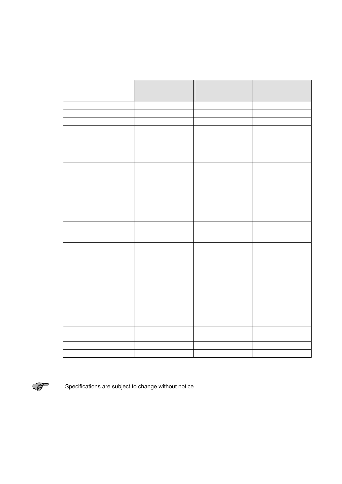
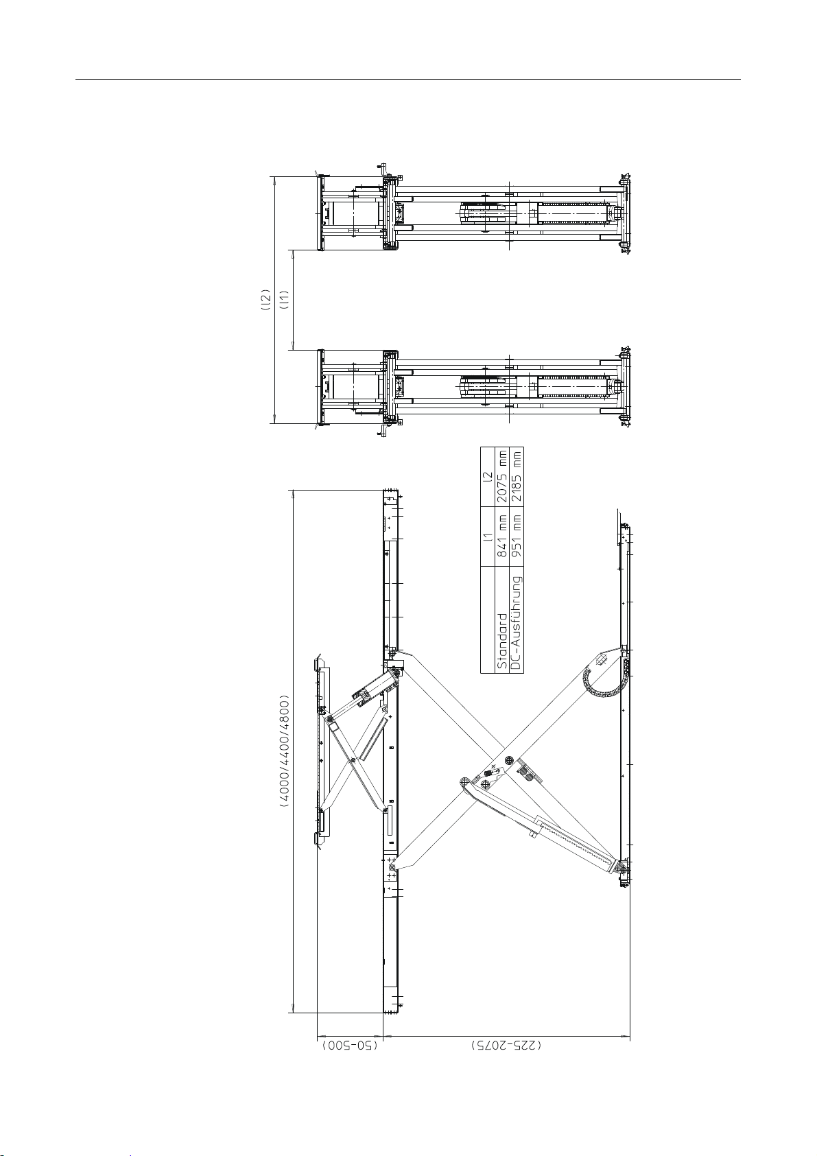
2.5 Specifications
DUO-GN
Rated load capacity 4200 kg 4200 kg 4200 kg
Full travel 1850 mm 1850 mm 1850 mm
Lifting height max. 2075 mm 2075 mm 2075 mm
Lifting height max. with
compensating plates
Lifting height min. 225 mm 225 mm 225 mm
Lifting height min. with
compensating plates
Dimensions of
standard version
Raising time approx. 45 s approx. 25 s approx. 12 s
Lowering time approx. 45 s approx. 25 s approx. 12 s
Anchoring with MKT
heavy-duty anchors
Anchoring with Fischer
heavy-duty anchors
Anchoring with UPAT
heavy-duty anchors
Motor power 2.5 kW 5.5 kW 2 x 5.5 kW
Supply voltage 3~ 400 V, 50 Hz 3~ 400 V, 50 Hz 3~ 400 V, 50 Hz
Wire size min. 2.5 mm² 4 mm² 6 mm²
Rated current 6.2 A 12 A 24 A
Fuse protection 16 A 25 A 35 A
Reservoir capacity approx. 38 l approx. 38 l approx. 38 l
Petroleum-based fluid
specification
Biodegradable fluid
specification
Working pressure max. 260 bar 260 bar 260 bar
Pump capacity 3.1 cm3/U 6 cm3/U 2 x 6 cm3/U
4000 mm x 2075 mm
2.5 kW
(Standard)
2125 mm 2125 mm 2125 mm
275 mm 275 mm 275 mm
L x W x H
x 225 mm
12x SZ-B 15/45
or
12x SZ-B 15/95
12x FH 15/50 B
or
12x FH 15/100 B
12x PS-B 15/50
or
12x PS-B 15/100
HLPD 32 min. HLPD 32 min. HLPD 32 min.
MAHA HLP 32 MAHA HLP 32 MAHA HLP 32
DUO-GN
5.5 kW
(Option)
L x W x H
4000 mm x 2075 mm
x 225 mm
12x SZ-B 15/45
or
12x SZ-B 15/95
12x FH 15/50 B
or
12x FH 15/100 B
12x PS-B 15/50
or
12x PS-B 15/100
DUO-GN
2 x 5.5 kW
(Option)
L x W x H
4000 mm x 2075 mm
x 225 mm
12x SZ-B 15/45
or
12x SZ-B 15/95
12x FH 15/50 B
or
12x FH 15/100 B
12x PS-B 15/50
or
12x PS-B 15/100
Specifications are subject to change without notice.
6 BA081101-en
Overview of DUO GN Lift (with Wheel-Free Jack)
BA081101-en 7
2.6 Sample Nameplate
Lifts of this model series have one large and one small nameplate each at the control desk and
at the hydraulic power unit. In the event of customer complaints, hotline requests or spare parts
orders, serial number and YoM of the lift should always be indicated.
SCHERENHEBEBÜHNE
Seriennummer / Baujahr: ***
Projekt: ***
Typ und Ausführung: ***
Spannung: ***
Frequenz: ***
Nennstrom: ***
Absicherung: ***
Traglast: ***
2.7 Installation
Lift installation and commissioning by authorized service personnel only.
Provision of handling means such as forklifts etc. is the owner's responsibility.
2.7.1 Location
The standard lift version may not be installed outdoors, in moist rooms, at hazardous locations,
or in the vicinity of explosives or flammable liquids.
Choice of a suitable lift location is the owner's responsibility.
2.7.2 Foundation
Prior to installation a sufficiently stable foundation and level lift bay floor shall be completed in
accordance with manufacturer recommendations.
Always use the current foundation plans.
Lift Version
Minimum Concrete
Thickness
DUO-GN 140 mm (reinforced)
Proof of safe floor load capacity is the owner's responsibility.
8 BA081101-en
 Loading...