

Page 1
DUO GN
Scissors Lift
Original Operating Instructions
BA081101-en
Fehler! Verwenden Sie die Registerkarte 'Start', um Name dem Text zuzuweisen, der hier angezeigt
werden soll.Fehler! Verwenden Sie die Registerkarte 'Start', um Name dem Text zuzuweisen, der hier
angezeigt werden soll.Fehler! Verwenden Sie die Registerkarte 'Start', um Name dem Text
zuzuweisen, der hier angezeigt werden soll.
Page 2

© MAHA Maschinenbau Haldenwang GmbH & Co. KG
Legal notice based on ISO 16016:
The reproduction, distribution and utilization of this document as well as the communication of
its contents to others without explicit authorization is prohibited. Offenders will be held liable for
the payment of damages. All rights reserved in the event of the grant of a patent, utility model or
design.
The contents of this edition have been checked with great care. However, errors cannot be fully
excluded. Subject to technical change without notice.
Document
Document №: BA081101-en
Approval Date: 20.10.2011
Manufacturer
MAHA Maschinenbau Haldenwang GmbH & Co. KG
Hoyen 20
87490 Haldenwang
Germany
Service
Phone: +49 (0)8
Fax: +49 (0)8374 585499
Fax Parts: +49 (0)8374 585565
Internet: http://www.maha.de
E-Mail: maha@maha.de
Hotline: +49 (0)1806 624260 for Brake Testers and Test Lanes
+49 (0)1806 62428
+49 (0)1806 62429
AutomoTec GmbH
Maybachstraße 8
87437 Kempten
Germany
Phone: +49 (0)1
Fax: +49 (0)1806 62425
Internet: http://www.au
E-Mail: service@automo-tec.com
374 5850
806 62425
tomo-tec.com
0 for Automotive Lifts
0 for Dynamometers and Emission Testers
0
5
II BA081101-en
Page 3

CONTENTS
1 Safety ......................................................................................................................... 1
1.1 Introduction .................................................................................................................................... 1
1.2 Safety Instructions for Commissioning ........................................................................................... 1
1.3 Safety Instructions for Operation ................................................................................................... 1
1.4 Safety Instructions for Servicing .................................................................................................... 2
1.5 Further Information ......................................................................................................................... 2
1.6 Safety Features .............................................................................................................................. 3
1.6.1 Controls........................................................................................................................... 3
1.6.2 Roll-off Protection ........................................................................................................... 3
1.6.3 Light Barriers .................................................................................................................. 3
1.6.4 Protection Bars ............................................................................................................... 3
1.6.5 Pressure Relief Valve ..................................................................................................... 3
1.6.6 Seat Valves ..................................................................................................................... 3
1.6.7 Safety Latch .................................................................................................................... 3
2 General Information .................................................................................................. 5
2.1 Description ..................................................................................................................................... 5
2.2 Intended Use .................................................................................................................................. 5
2.3 Standard Delivery ........................................................................................................................... 5
2.4 Noise Emission .............................................................................................................................. 5
2.5 Specifications ................................................................................................................................. 6
2.6 Sample Nameplate ......................................................................................................................... 8
2.7 Installation ...................................................................................................................................... 8
2.7.1 Location .......................................................................................................................... 8
2.7.2 Foundation ...................................................................................................................... 8
2.7.3 Power and Air Supply ..................................................................................................... 9
3 Operation ................................................................................................................. 11
3.1 Defects / Malfunctions .................................................................................................................. 11
3.2 Controls ........................................................................................................................................ 12
3.2.1 Operator's Controls ....................................................................................................... 12
3.2.2 Main Switch .................................................................................................................. 13
3.3 Operating the Lift .......................................................................................................................... 14
3.3.1 Switch-on / Switch-off ................................................................................................... 14
3.3.2 Protection against Unauthorized Usage ....................................................................... 14
3.3.3 Raising .......................................................................................................................... 15
3.3.4 Working with the Vehicle in Raised Position ................................................................ 15
3.3.5 Lighting ......................................................................................................................... 15
3.3.6 Lowering ....................................................................................................................... 16
3.3.7 Hydraulic Inclination ...................................................................................................... 17
3.3.8 Setting the Runways on Locks for Wheel Alignment .................................................... 17
3.4 Automatic Runway Synchronization ............................................................................................ 18
3.4.1 Lift without Inclination Device ....................................................................................... 18
3.4.2 Lift with Hydraulic Inclination Device ............................................................................ 18
3.4.3 Lift with Permanent Inclination Device .......................................................................... 19
3.5 Cross Member .............................................................................................................................. 20
3.6 Manual Lowering .......................................................................................................................... 21
3.7 Manual Lowering (Lift with Center Cover) .................................................................................... 22
3.8 Operation of Wheel-Free Jack ..................................................................................................... 23
3.8.1 Preparations ................................................................................................................. 23
3.8.2 Raising .......................................................................................................................... 23
3.8.3 Lowering ....................................................................................................................... 23
3.8.4 Manual Lowering .......................................................................................................... 24
3.8.5 Manual Equalization ..................................................................................................... 25
BA081101-en III
Page 4

4 Maintenance ............................................................................................................. 27
4.1 Annual Inspection ......................................................................................................................... 27
4.2 Checking the Fluid Level .............................................................................................................. 27
4.3 Greasing Points ............................................................................................................................ 28
4.4 Greasing Points at the Wheel-Free Jack ..................................................................................... 29
4.5 Pneumatic Floor Cover ................................................................................................................ 30
4.6 Cleaning ....................................................................................................................................... 30
4.7 Troubleshooting ........................................................................................................................... 30
5 Life Expectancy ....................................................................................................... 32
6 Dismantling .............................................................................................................. 32
7 Disposal ................................................................................................................... 32
8 Contents of the Declaration of Conformity ........................................................... 32
IV BA081101-en
Page 5
1 Safety
1.1 Introduction
Thoroughly read this manual before operating the lift and comply with the instructions. Always
display the manual in a conspicuous location.
Personal injury and property damage incurred due to non-compliance with these safety
instructions are not covered by the product liability regulations.
Warning: Failure to comply with instructions could result in personal injury.
Caution: Failure to comply with instructions could result in property damage.
Important information.
Carefully observe all safety instructions. They are provided to warn of dangers and help prevent
personal injury and property damage.
It is the operator’s responsibility to comply with the applicable accident prevention regulations
and to bring them up to date continually.
1.2 Safety Instructions for Commissioning
Installation and commissioning by authorized service personnel only.
The standard lift version may not be installed and commissioned in the vicinity of explosives
or flammable liquids. Lifts with explosion protection are available on request.
1.3 Safety Instructions for Operation
Read the operating manual.
Only use the lift for its intended purpose.
Do not overload the lift. The rated load capacity is indicated on the lift nameplate.
Lift operation by trained personnel over 18 years only.
Keep the lift area free of obstructions.
Closely watch the vehicle and the lift during raising and lowering cycles.
Do not allow anyone to stay in lift area during raising and lowering cycles.
Do not allow anyone to climb on lift or raised vehicle.
Secure the vehicle against inadvertent roll-off by using chocks.
Keep the lift and vehicle free of tools, parts etc.
Keep the lift and lift area clean.
The main switch serves as emergency switch. In case of emergency turn to position 0.
BA081101-en 1
Page 6

Protect the lift against unauthorized usage by padlocking the main switch.
Provide adequate ventilation when working on operating internal combustion engines.
Danger of carbon-monoxide poisoning!
1.4 Safety Instructions for Servicing
Maintenance or repair work by authorized service personnel only.
Turn off and padlock the main switch before servicing the lift.
Work on pulse generators or proximity switches by authorized service personnel only.
Work on the electrical equipment by certified electricians only.
Ensure that ecologically harmful substances are disposed of only in accordance with the
appropiate regulations.
1.5 Further Information
Take precautions against soil contamination by hydraulic fluid.
Position the control panel in such a way that the main switch is easily accessible at all times.
For low shop ceilings the installation of a safety light barrier is recommended.
Protect the plunger rods against soiling and damage.
Drive on runways only in their fully retracted position.
The use of high pressure or steam jet cleaners could result in equipment damage.
The use of cleansing agents which attack paintwork, coatings, or sealing materials could
result in equipment damage.
2 BA081101-en
Page 7

1.6 Safety Features
1.6.1 Controls
1.6.1.1 Dead Man's Type Control
The operator is required to hold the control in the engaged position to initiate and maintain a
particular operation.
1.6.1.2 Front Rings
The control buttons are provided with front rings to prevent inadvertent actuation.
1.6.2 Roll-off Protection
Once the runways are raised, the approach ramps rise and act as chocks.
1.6.3 Light Barriers
1.6.3.1 Longitudinal Light Barriers (Pinch Point Protection)
The outside edges of the runways are equipped with light barriers. Once the light beam is
interrupted the lift stops immediately.
1.6.3.2 Transverse Light Barrier (Runway Synchronization Check)
This light barrier is used to check the runway synchronization. Once a certain level difference is
exceeded the lift stops immediately.
1.6.4 Protection Bars
The surface mounted version is equipped with longitudinal protection bars.
1.6.5 Pressure Relief Valve
The working pressure is limited to a maximum of 260 bar by the pressure relief valve.
1.6.6 Seat Valves
Positive-control seat valves at the hydraulic cylinders prevent sudden lowering movements in
case of a rapid pressure drop due to line break.
1.6.7 Safety Latch
The safety latch prevents sudden lowering movements caused by pressure drop or cylinder
leakage.
BA081101-en 3
Page 8

4 BA081101-en
Page 9
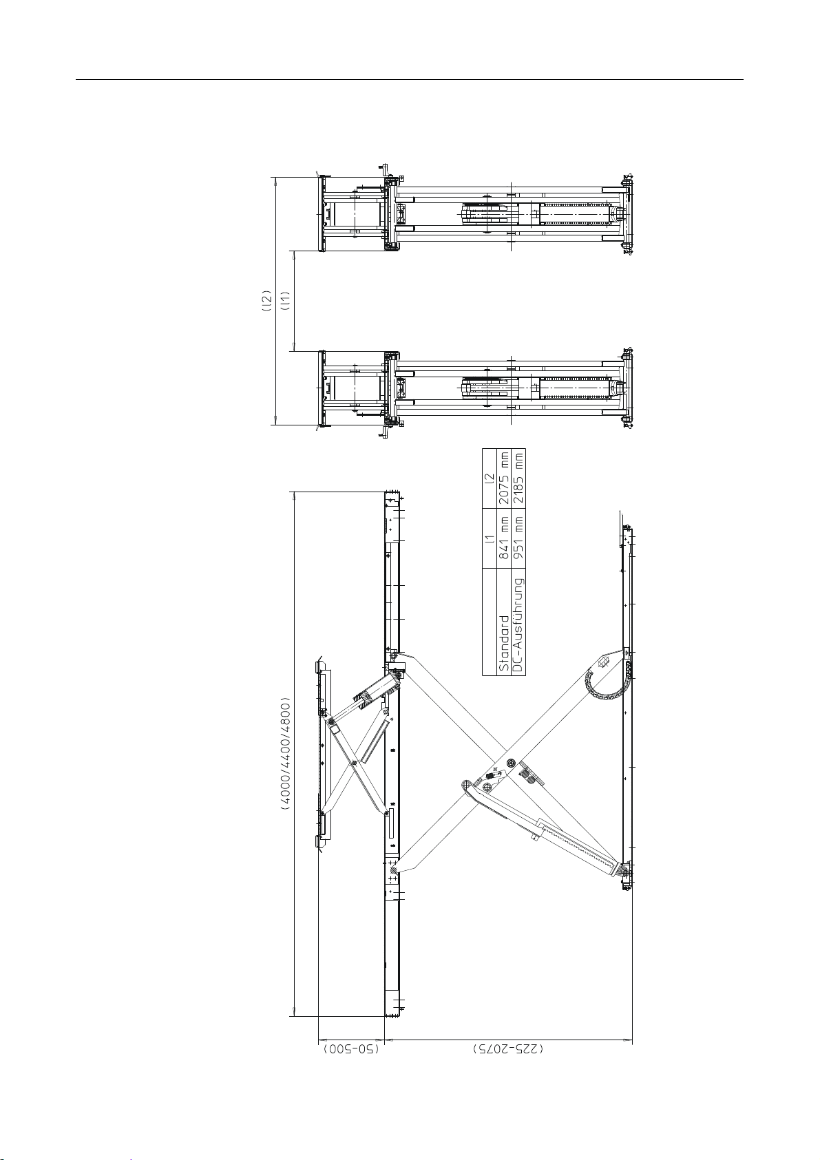
2 General Information
2.1 Description
The DUO-GN is a scissors lift equipped with runways. In its standard version, the lift has a
maximum lifting height of 2075 mm.
2.2 Intended Use
The lift is intended to be used for the safe lifting of automotive vehicles. Be sure to observe the
rated load capacity and load distribution.
Lift Version Load Capacity
DUO-GN 4,200 kg
2.3 Standard Delivery
Scissors lift, model DUO-GN
Control desk including power unit
Cable covers
Two approach ramps (for surface mounted version) or four flaps (for flush mounted version)
Two pneumatic quick couplers at runway inside
Operating manual
2.4 Noise Emission
The sound pressure level is below 70 dB(A) in the working area of the operator.
BA081101-en 5
Page 10
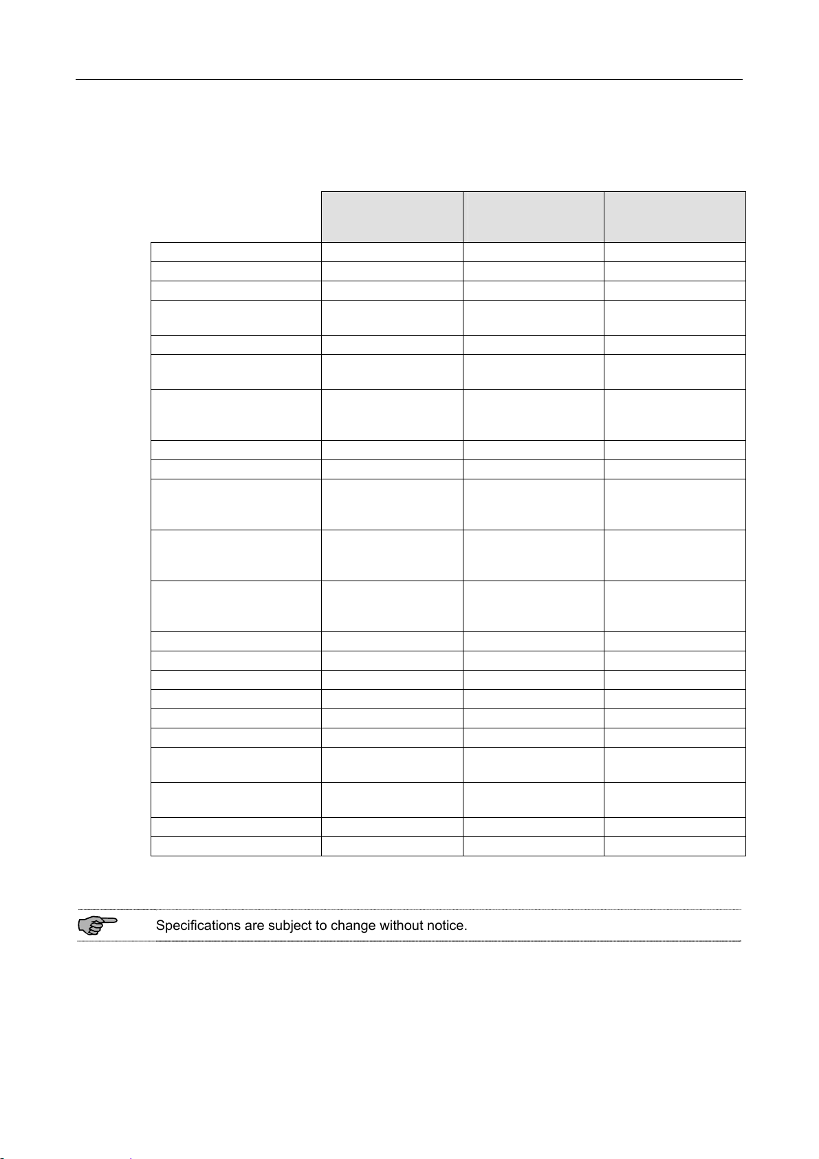
2.5 Specifications
DUO-GN
Rated load capacity 4200 kg 4200 kg 4200 kg
Full travel 1850 mm 1850 mm 1850 mm
Lifting height max. 2075 mm 2075 mm 2075 mm
Lifting height max. with
compensating plates
Lifting height min. 225 mm 225 mm 225 mm
Lifting height min. with
compensating plates
Dimensions of
standard version
Raising time approx. 45 s approx. 25 s approx. 12 s
Lowering time approx. 45 s approx. 25 s approx. 12 s
Anchoring with MKT
heavy-duty anchors
Anchoring with Fischer
heavy-duty anchors
Anchoring with UPAT
heavy-duty anchors
Motor power 2.5 kW 5.5 kW 2 x 5.5 kW
Supply voltage 3~ 400 V, 50 Hz 3~ 400 V, 50 Hz 3~ 400 V, 50 Hz
Wire size min. 2.5 mm² 4 mm² 6 mm²
Rated current 6.2 A 12 A 24 A
Fuse protection 16 A 25 A 35 A
Reservoir capacity approx. 38 l approx. 38 l approx. 38 l
Petroleum-based fluid
specification
Biodegradable fluid
specification
Working pressure max. 260 bar 260 bar 260 bar
Pump capacity 3.1 cm3/U 6 cm3/U 2 x 6 cm3/U
4000 mm x 2075 mm
2.5 kW
(Standard)
2125 mm 2125 mm 2125 mm
275 mm 275 mm 275 mm
L x W x H
x 225 mm
12x SZ-B 15/45
or
12x SZ-B 15/95
12x FH 15/50 B
or
12x FH 15/100 B
12x PS-B 15/50
or
12x PS-B 15/100
HLPD 32 min. HLPD 32 min. HLPD 32 min.
MAHA HLP 32 MAHA HLP 32 MAHA HLP 32
DUO-GN
5.5 kW
(Option)
L x W x H
4000 mm x 2075 mm
x 225 mm
12x SZ-B 15/45
or
12x SZ-B 15/95
12x FH 15/50 B
or
12x FH 15/100 B
12x PS-B 15/50
or
12x PS-B 15/100
DUO-GN
2 x 5.5 kW
(Option)
L x W x H
4000 mm x 2075 mm
x 225 mm
12x SZ-B 15/45
or
12x SZ-B 15/95
12x FH 15/50 B
or
12x FH 15/100 B
12x PS-B 15/50
or
12x PS-B 15/100
Specifications are subject to change without notice.
6 BA081101-en
Page 11
Overview of DUO GN Lift (with Wheel-Free Jack)
BA081101-en 7
Page 12
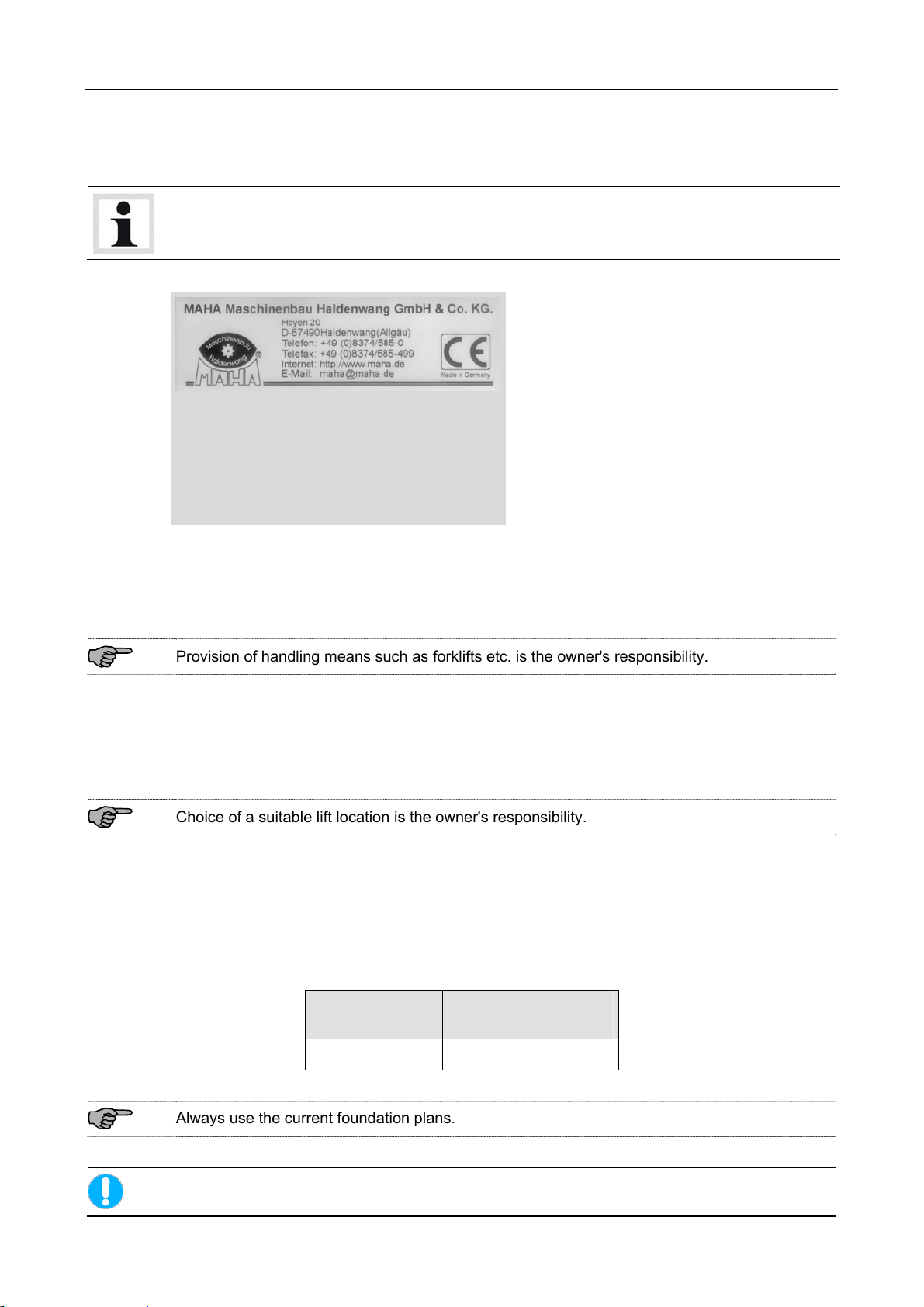
2.6 Sample Nameplate
Lifts of this model series have one large and one small nameplate each at the control desk and
at the hydraulic power unit. In the event of customer complaints, hotline requests or spare parts
orders, serial number and YoM of the lift should always be indicated.
SCHERENHEBEBÜHNE
Seriennummer / Baujahr: ***
Projekt: ***
Typ und Ausführung: ***
Spannung: ***
Frequenz: ***
Nennstrom: ***
Absicherung: ***
Traglast: ***
2.7 Installation
Lift installation and commissioning by authorized service personnel only.
Provision of handling means such as forklifts etc. is the owner's responsibility.
2.7.1 Location
The standard lift version may not be installed outdoors, in moist rooms, at hazardous locations,
or in the vicinity of explosives or flammable liquids.
Choice of a suitable lift location is the owner's responsibility.
2.7.2 Foundation
Prior to installation a sufficiently stable foundation and level lift bay floor shall be completed in
accordance with manufacturer recommendations.
Always use the current foundation plans.
Lift Version
Minimum Concrete
Thickness
DUO-GN 140 mm (reinforced)
Proof of safe floor load capacity is the owner's responsibility.
8 BA081101-en
Page 13

2.7.3 Power and Air Supply
Power supply cable and air hose should be run to the control desk location with an excess
length of at least 1.5 m.
2.7.3.1 Power Supply
3~ + N + PE 400 V, 50 Hz. Select a wire size appropriate for lift model and cable length.
Standard 2.5 16 6.2
Option 5.5 25 12
Option 2 x 5.5 35 24
2.7.3.2 Air Supply
Motor power in kW Time-delay fuse in A Rated current in A
R1/4" incl. maintenance unit; delivery rate and working pressure appropriate for lift model.
BA081101-en 9
Page 14

10 BA081101-en
Page 15

3 Operation
Lift operation by trained personnel over 18 years only.
Apply the parking brake after positioning the vehicle on the lift.
Do not allow anyone to stay in lift area during raising and lowering cycles.
Closely watch the vehicle and the lift during raising and lowering cycles.
Observe the rated load capacity.
Do not allow anyone to climb on lift or raised vehicle.
Drive onto runways only in their fully lowered position.
The DUO-GN lift can be equipped with various accessories. In some cases your lift version may
differ slightly from the illustrations in this manual.
3.1 Defects / Malfunctions
In case of defects or malfunctions such as jerky lift movement or deformation of the
superstructure, support or lower the lift immediately.
Turn off and padlock the main switch. Contact qualified service personnel.
BA081101-en 11
Page 16

3.2 Controls
3.2.1 Operator's Controls
Description Symbol
Power (white signal lamp)
Lights up once lift is ready for operation.
Error (red signal lamp)
Lights up or flashes in the event of errors such as light barrier interruptions.
Axle Jack Position (orange signal lamp) [optional]
Only available with option "Floor Cover with Defined Axle Jack Position".
Lights up once axle jack is moved from its defined home position.
The lift can only be lowered to bottom position with axle jack in defined home
position.
Raise (button)
Press and hold this button to raise the lift. Lift stops once button is released
or upward travel limit is reached.
Lift stops if transverse light barrier (synchronization check) is interrupted.
Lift is inoperative until obstacle/error has been removed.
Lower (button)
Press and hold this button to lower the lift. Lift stops once button is released
or downward travel limit is reached.
For lifts equipped with Set-on-Locks function: Lift slightly raises to disengage
the locking latches before lowering cycle starts.
Lift stops if one of the longitudinal light barriers or the transverse light barrier
is interrupted. Lift is inoperative until obstacle/error has been removed.
Lighting (switch) [optional]
Use this switch to turn on and off the runway lighting.
Set on Locks (button/green signal lamp) [optional]
Locking latch engages nearest serration.
The signal lamp will not light up until the main cylinders (and the inclination
cylinders) are depressurized.
Enable Runway Inclination (button) [optional]
Use this button to activate the hydraulic runway inclination for vehicles with
low ground clearance.
Disable Runway Inclination (button) [optional]
Use this button to reset the runways to their horizontal position.
12 BA081101-en
Page 17

Raise Wheel-Free Jack (button) [optional]
Use this button to raise the wheel-free jack.
Lower Wheel-Free Jack (button) [optional]
Use this button to lower the wheel-free jack.
The availability of the above functions depends on the accessory equipment of your lift.
See operating manuals provided.
3.2.2 Main Switch
Position 1: Lift is ready for operation.
Position 0: Lift is disconnected from power supply. In this position
the main switch can be padlocked.
In case of emergency turn the main switch to position 0.
BA081101-en 13
Page 18

3.3 Operating the Lift
3.3.1 Switch-on / Switch-off
In case of emergency turn the main switch to position 0.
ON: Turn main switch to position 1.
The POWER signal lamp lights up
once the lift is ready for operation.
OFF: Turn main switch to position 0.
The POWER signal lamp
extinguishes.
After switch-on wait approx. 3 seconds until the control electronics have performed a self-test.
3.3.2 Protection against Unauthorized Usage
With main switch in position 0 push yellow
slider and padlock the switch.
14 BA081101-en
Page 19

3.3.3 Raising
Closely watch the vehicle and the lift during raising and lowering cycles.
Do not allow anyone to stay in lift area.
Be sure lift is in bottom position.
Slowly center vehicle on runways.
Secure vehicle using parking brake and chocks.
Leave vehicle and stay clear of lift area.
Press and hold RAISE button until lift has reached desired height.
Lift stops once button is released or upward travel stop is reached.
3.3.4 Working with the Vehicle in Raised Position
Observe all accident prevention regulations.
Do not allow anyone to stay under the vehicle.
Avoid excessive rocking of vehicle or lift.
Keep lift and vehicle free of tools, parts, debris etc.
3.3.5 Lighting
Runway lighting (optional).
Lighting OFF
Lighting ON
BA081101-en 15
Page 20

3.3.6 Lowering
Closely watch the vehicle and the lift during raising and lowering cycles.
Do not allow anyone to stay in lift area.
Press and hold LOWER button until lift has reached desired height.
Before starting the lowering cycle the lift will slightly raise to disengage the
locking latch.
Lift stops once button is released or downward travel stop is reached.
Make sure lift is fully lowered before removing the vehicle.
Release parking brake, remove chocks.
Drive vehicle off the lift.
If the lift is equipped with option "Set on Locks for Wheel Alignment", press and
If equipped with option "Pinch Point Protection with Audible Warning Device“, the lift will pause
short of downward travel stop.
Release LOWER button and press again. A signal sounds until the lift is in bottom position.
hold the LOWER button until the green signal lamp SET ON LOCKS lights up.
This is to ensure troublefree operation of the automatic runway synchronization.
If the lift is equipped with option "Floor Cover for Defined Axle Jack Position", the
lift can only be lowered to bottom position if the axle jack is in defined home
position.
Once the axle jack is in defined home position, the signal lamp AXLE JACK
POSITION goes out.
16 BA081101-en
Page 21

3.3.7 Hydraulic Inclination
Optionally available for vehicles with lowered chassis.
Do not drive onto or off the runways before they are in fully inclined position.
Press and hold ENABLE RUNWAY INCLINATION button until the runways
are in fully inclined position.
Slowly center vehicle on runways.
Secure vehicle using parking brake and chocks.
Leave vehicle and stay clear of lift area.
Press and hold DISABLE RUNWAY INCLINATION button until the runways
are in horizontal position again.
For raising and lowering the lift see respective sections in this manual.
3.3.8 Setting the Runways on Locks for Wheel Alignment
Optionally available.
The green signal lamp lights up once the locking latches have fully engaged the serrations and
the system has been depressurized.
If the lift is equipped with double latches, check all four latches for proper engagement.
Press and hold SET ON LOCKS button until green signal lamp lights up.
If the green signal lamp does not light up, raise the lift briefly; then press and hold SET ON
LOCKS button again.
If the error persists, activate the automatic runway synchronization as follows:
Press and hold LOWER button until lift is in bottom position and green signal lamp lights up.
Then raise lift to desired height. Press and hold SET ON LOCKS button again.
BA081101-en 17
Page 22

3.4 Automatic Runway Synchronization
Two "reference events" are required to ensure proper function of the runway synchronization
(optional):
Lowering to bottom position to determine the zero point.
Raising from bottom position to determine the filling ratio of the cylinder.
The procedures explained below serve to activate the automatic runway synchronization. The
procedures can be carried out with and without vehicle and should be repeated periodically.
3.4.1 Lift without Inclination Device
After the lift has reached bottom position keep holding the LOWER button for
a few seconds.
Lift with Set-on-Locks function: The green signal lamp lights up once the lift
has reached bottom position.
3.4.2 Lift with Hydraulic Inclination Device
After fully lowering the lift, press and hold the DISABLE RUNWAY
INCLINATION button until the runways are in horizontal position.
Press and hold the LOWER button for a few seconds.
Lift with Set-on-Locks function: The green signal lamp lights up once the lift
has reached bottom position.
18 BA081101-en
Page 23

3.4.3 Lift with Permanent Inclination Device
Press and hold the RAISE button until the runway supports become
accessible.
Remove the supports from under both runways.
Lower the lift. After the lift has reached bottom position keep holding the
LOWER button for a few seconds.
Lift with Set-on-Locks function: The green signal lamp lights up once the lift
has reached bottom position.
Raise the lift to a convenient height.
Reinsert the runway supports.
BA081101-en 19
Page 24

3.5 Cross Member
To increase the lift stability, the runways can be optionally equipped with a cross member.
Once a certain level difference is exceeded, the cross member will automatically disengage to
avoid damage to the lift.
Periodically check the cross member for secure engagement (see illustration below, position 1).
Engaged position
1
Partially disengaged position
2
Fully disengaged position
3
To reinstall the partially or fully disengaged cross member proceed as follows:
Release the catch spring from the disengaged fork head of the cross member. Remove the
hinge pin (including catch spring).
Synchronize the runways.
Place the fork head in the holding bracket and insert the hinge pin.
Secure the hinge pin by locking the catch spring.
20 BA081101-en
Page 25

3.6 Manual Lowering
In case of motor defect or power failure the lift can be lowered manually. The lift may only be
lowered, not raised.
Authorized personnel only! Do not restart the lift before the error has been remedied.
1 Open the solenoid valve first at the slave
side cylinder (Y5), then at the master
side cylinder (Y4).
2 Position the slide shoes under the
latches at both cylinders.
The slide shoes prevent the latches from
engaging the toothed rack.
3 Push the lowering valve (Y2) at the
hydraulic power unit.
Lift begins to lower slowly.
4 Once the error has been remedied, raise
the lift without load and close the
solenoid valves finger tight.
BA081101-en 21
Page 26

3.7 Manual Lowering (Lift with Center Cover)
In case of motor defect or power failure the lift can be lowered manually. The lift may only be
lowered, not raised.
Authorized personnel only! Do not restart the lift before the error has been remedied.
1 Open the solenoid valve (A) first at
the slave side cylinder (Y5), then at
the master side cylinder (Y4).
A
2 If required, disengage the safety latches from
the toothed rack using the hand pump (B).
B
D
E
C
3 Position the slide shoes (C) under
the latches to prevent them from
engaging the rack.
4 Remove the hose (D) from the control unit and
push it against the nozzle of the compressedair gun (E).
5 To lower the lift, pull the trigger. To stop the lift, release the trigger and remove the hose from
the gun nozzle.
22 BA081101-en
Page 27

3.8 Operation of Wheel-Free Jack
Ensure that the runways and the wheel-free jack are in fully lowered position before driving on
or off the lift.
3.8.1 Preparations
Center the vehicle over the wheel-free jack.
Lift the extensions using the handles (1) and
position them (2) under the vehicle lift points.
Use plastic spacer blocks under the vehicle
lift points.
3.8.2 Raising
After raising the vehicle briefly, stop and check the extensions for secure contact at the
vehicle lift points.
Watch vehicle and jack while raising. Do not allow anyone to stay in lift area.
Use this button to raise the jack to the desired height.
The jack stops once the button is released.
3.8.3 Lowering
Watch vehicle and jack while lowering.
Use this button to lower the jack to the desired height.
The jack stops once the button is released.
BA081101-en 23
Page 28

3.8.4 Manual Lowering
In case of motor defect or power failure the lift can be lowered manually. The lift may only be
lowered, not raised.
Authorized personnel only! Do not restart the lift before the error has been remedied.
1 Open the solenoid valve first at the slave
side cylinder (Y11), then at the master
side cylinder (Y10).
2 Push the lowering valve (Y9.2) at the
hydraulic cylinder.
Wheel-free jack begins to lower slowly.
3 Once the error has been remedied, raise
the wheel-free jack without load and
close the solenoid valves finger tight.
24 BA081101-en
Page 29

3.8.5 Manual Equalization
1 Push and hold the button beneath the
control desk.
The slave cylinder of the wheel-free jack is
now disabled, only the slave cylinder can
be operated.
2 Use buttons "Raise WFJ" and "Lower
WFJ" to equalize both sides of the wheelfree jack.
3 Release the button beneath the control desk. Master and slave side are now in synchronous
operation.
BA081101-en 25
Page 30

26 BA081101-en
Page 31

4 Maintenance
Turn off and lock the main switch before servicing the lift.
4.1 Annual Inspection
The maintenance interval prescribed by the manufacturer is 12 (twelve) months.
This maintenance interval refers to normal workshop usage. If the equipment is used more
frequently or under severe operating conditions (e.g. outdoors, in car wash), the interval
must be reduced accordingly.
Maintenance work shall be done only by authorized and trained service technicians provided
by the manufacturer, licensed dealers or service partners.
In case of non-compliance the manufacturer's warranty becomes void.
4.2 Checking the Fluid Level
1 Lower lift and whel-free jack to bottom position.
2 Check the fluid level (see label on power unit).
3 Open the filler neck and top up the reservoir. Specification and quantity: See label on power
unit.
4 Also carry out a visual check of all hydraulic pipes and hoses.
Replace the hydraulic fluid periodically, depending on aging, soiling and water absorption.
When topping up, use fluid with the same specification only.
If the lift is operated permanently at an ambient temperature of < 15 °C, use hydraulic fluid
with a lower viscosity.
The pressure hoses should be replaced as required, but after six years at the latest.
BA081101-en 27
Page 32

4.3 Greasing Points
4
4
3
2
1
5
5
Cylinders
Quarterly grease the cylinder and plunger hinges through lubricator nipples 1.1 and 1.2.
Remove waste grease.
Lifts equipped with double latch:
Also grease the hinges of the pneumatically actuated cylinders for the Set-on-Locks function.
Scissors Pins
Quarterly grease the scissors pins on the outside and inside through lubricator nipples 2.1 and
2.2. Remove waste grease.
Base Plate Tracks
Quarterly clean and slightly grease the base plate tracks (3).
Runway Tracks
Quarterly clean and slightly grease the runway tracks (4).
Runway tracks equipped with rollers: Clean but do not grease the tracks.
28 BA081101-en
Page 33

Thrust Bearings
Quarterly grease the thrust bearings through the lubricator nipples (5). Remove waste grease.
Lift should be greased monthly for severe use applications.
4.4 Greasing Points at the Wheel-Free Jack
Tracks inside the Lift Runway
Quarterly clean and slightly grease the tracks inside the runway (1).
Tracks inside the Wheel-Free Jack
Quarterly clean and slightly grease the tracks inside the wheel-free jack (2).
BA081101-en 29
Page 34

4.5 Pneumatic Floor Cover
Only for lifts with pneumatic floor cover: Quarterly clean and grease the plastic guides of the
limit stops.
4.6 Cleaning
Do not use high pressure / steam jet cleaners or caustic cleaning agents which attack
coatings and sealing materials. Risk of damage!
Periodically wash off aggressive substances such as salt water, brake fluid etc. and treat the lift
with oil or wax spray.
Repair damage to the paintwork immediately to prevent corrosion.
The RAL number is available through the manufacturer.
4.7 Troubleshooting
Trouble
Possible Cause Remedy
Runway lighting does not burn.
Fuse F2 blown. Replace fuse F2.
POWER signal lamp not burning. Lift does not respond.
Main switch off. Turn on main switch.
Power fuse blown. Replace power fuse.
Primary fuse F1 of power pack G1 blown. Replace fuse F1.
Secondary fuses of power pack G1 blown. Replace fuses.
POWER and ERROR signal lamps burning. Lift does not respond.
Protective motor switch Q2/Q3 off. Turn on protective motor switch.
Ceiling light barrier B4 dirty. Cautiously clean light barrier.
POWER signal lamp lighting up, ERROR signal lamp flashing slowly. Lift can be raised only.
Longitudinal LBs triggered by obstacle. Remove obstacle.
Longitudinal LBs dirty. Cautiously clean transmitters / receivers.
Longitudinal LBs defective. Contact service.
POWER signal lamp lighting up, ERROR signal lamp flashing quickly. Lift does not respond.
Transverse LB dirty. Cautiously clean transmitter / receiver.
Apertures of transverse LB dirty. Clean apertures (see illustration below).
Transverse LB triggered by obstacle. Remove obstacle.
Transverse LB defective. Contact service.
POWER signal lamp lighting up, ERROR signal lamp flashing quickly. Runways unequal in
height, lift does not respond.
Transverse LB triggered by unequal load
distribution on runways.
Runways unequal in height despite equal
load distribution. Transverse LB triggered.
Button SET ON LOCKS pressed: Runways
engage different serrations, are unequal in
height. Transverse LB triggered.
See section "Runway Synchronization
Check“.
See section "Runway Synchron. Check“.
Contact service if required.
See section "Runway Synchronization
Check“.
30 BA081101-en
Page 35

Motor running, but pressure build-up insufficient to raise lift.
Manual lowering screw open. Close screw.
Hydraulic system leaking. Remove leakage.
Low fluid level. Check fluid level, refill as required.
Vehicle too heavy. Check vehicle weight, reduce if possible.
Repair work on safety devices and electrical equipment by authorized personnel only.
The transverse LB apertures (Ø approx. 3 mm)
are located opposite each other at one end of
the runways.
BA081101-en 31
Page 36

5 Life Expectancy
In its standard version, this product is designed for 22,000 load cycles based on EN 1493.
The maximum period of normal use in relation to the possible product life expectancy shall be
evaluated and scheduled by a qualified person during the annual safety inspection.
6 Dismantling
Decommissioning and dismantling of the equipment may be done only by specially authorized
7 Disposal
and trained personnel provided by the manufacturer, licensed dealers or service partners.
Pay attention to the product and safety data sheets of the lubricant used. Avoid damage to the
environment. Should a disposal of the device be necessary it must be done in adherence with
locally applicable legal regulations regarding environmental protection. Remove all materials
properly sorted out and bring them to a suitable waste disposal service. Collect operating
materials such as grease, oils, coolant, solvent-based cleaning fluids etc. in suitable containers
and dispose of in an environmentally protective manner.
Alternatively, you may take the equipment to a specialised waste management plant to ensure
8 Contents of the Declaration of Conformity
that all components and operating liquids are properly disposed of.
MAHA Maschinenbau Haldenwang GmbH & Co. KG
herewith declares as a manufacturer its sole responsibility to ensure that the product named
hereafter meets the safety and health regulations both in design and construction required by
the EC directives stated below.
This declaration becomes void if any change is made to the product that was not discussed and
approved by named company beforehand.
Model: DUO GN
Designation: Scissors Lift; Rated Load Capacity 4200 kg
EC Directives: 2006/42/EC; 2004/108/EC
EN Standards: EN 1493; EN 60204-1
32 BA081101-en
Page 37

 Loading...