

Maguire Products VBD-150, VBD-300 Maintenance Manual
MAGUIRE PRODUCTS, INC.
Vacuum Batch Dryer Touchscreen
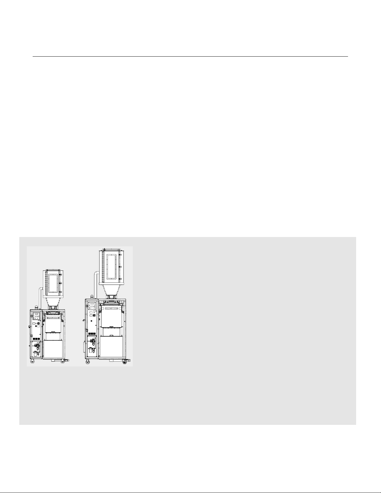
VBD-150
VBD-300
Vacuum Batch Dryer
Touch Screen Controller
INSTALLATION • OPERATION • MAINTENANCE
Rev. October 5, 2018
Copyright © Maguire Products, Inc. 2018

Maguire Products, Inc.
2
VBD - Vacuum Dryer TSC

Maguire Products, Inc.
3
VBD - Vacuum Dryer TSC
VBD-150 / VBD-300 - Vacuum Dryer
This document is the Original Instructions manual of the Maguire VBD-150 and VBD-300 Vacuum Dryer
equipped with the Touchscreen Controller.
Copyright © 2018 Maguire Products Inc.
The information contained within this manual including any translations thereof, is the property of Maguire
Products Inc. and may not be reproduced, or transmitted in any form or by any means without the express
written consent of Maguire Products Inc.
To every person concerned with use and maintenance of the Maguire VBD-150 and VBD-300 it is
recommended to read thoroughly these operating instructions. Maguire Products Inc. accepts no responsibility
or liability for damage or malfunction of the equipment arising from non-observance of these operating
instructions.
To avoid errors and to ensure trouble-free operation, it is essential that these operating instructions are read and
understood by all personnel who are to use the equipment.
Should you have problems or difficulties with the equipment, please contact Maguire Products Inc. or your local
Maguire distributor.
Manufacturer’s Contact Information
Maguire Products Inc.
11 Crozerville Road
Aston, PA. 19014
Phone: 610.459.4300
Fax: 610.459.2700
Website: http://www.maguire.com
Email: info@maguire.com

Maguire Products, Inc.
4
VBD - Vacuum Dryer TSC
Accuracy of this Manual
We make every effort to keep this manual as correct and current as possible. However,
technology and product changes may occur more rapidly then the reprinting of this manual.
Generally, modifications made to the dryer design or to the operation of the software are
may not reflected in the manual for several months. The date at the footer of this manual
will indicate approximately how current this manual is. Likewise, your Dryer may have been
produced at an earlier time and the information in this manual may not accurately describe
your Dryer since this manual is written for the current line of Dryers in production (as of the
date in the footer). We always reserve the right to make these changes without notice, and
we do not guarantee the manual to be entirely accurate. If you question any information in
this manual, or find errors, please let us know so that we may make the required
corrections or provide you with accurate information. Additionally, we will gladly provide
you with an updated copy of any manuals you need at any time. We welcome comments
and suggestions on ways we can improve this manual.
For additional information, or to download the latest copy of this manual or any other
Maguire manual, please visit our website or contact us directly.
On the Web at: www.maguire.com
Maguire Products Inc.
Main Headquarters
11 Crozerville Road
Aston, PA 19014
Tel: 610.459.4300
Fax: 610.459.2700
Email:
info@maguire.com
Maguire Europe
Tame Park
Tamworth
Staffordshire
B775DY
UK
Tel: + 44 1827 265 850
Fax: + 44 1827 265 855
Email:
info@maguire-europe.com
Maguire Products Asia PTE LTD
15 Changi North Street 1
#01-15, I-Lofts
Singapore 498765
Tel: 65 6848-7117
Fax: 65 6542-8577
magasia@maguire-products.com.sg
Maguire Italy
Via Zancanaro 40
35020 Vigorovea (PD)
Tel: +39 049 970 54 29
Fax: +39 049 971 18 38
Email:
info@maguire-italia.it
Please e-mail comments and suggestions to: support@maguire.com

Maguire Products, Inc.
5
VBD - Vacuum Dryer TSC
Table of Contents
INSTALLATION 8
VBD-150 Dryer Assembly 11
Dryer Connections 18
Compressed Air Connection 18
Electrical Connection 19
Dryer Overview 21
Home Screen Overview 22
Controller Overview 22
Setup Menu Map - Brief Explanation 30
Setup Menu Options Explained 35
Parameters Explained 40
Changing Parameters 47
Batch Mode 48
Communication Setup 49
Operation 23
Startup and Operation 23
Recommended Drying Temperatures 29
Maintenance 51
Drain and purge Air Filter / Regulator 51
Air Pressure Adjustments 51
Replacing the Air Filter 51
Loadcell Calibration 52
Temperature and Pressure Verification 54
Cleanout Procedure 55
Vacuum Chamber Removal 58
Printing Parameters, Events and Alarms 62
Alarms - Cause and Solution 68
Save / Restore User Settings 72
Firmware Updates 73
Theory of Operation / Performance 74
Technical Documentation 75
VBD-150 Technical Specifications 75
VBD-150 Diagrams 76
VBD-150 Recommended Spare Parts List 86
VBD-300 Technical Specifications 87
VBD-300 Diagrams 88
VBD-300 Recommended Spare Parts List 96
Declaration of Conformity 97
Technical Support / Contact Information 98

Maguire Products, Inc.
6
VBD - Vacuum Dryer TSC
Warranty – Exclusive 5-Year
MAGUIRE PRODUCTS OFFERS THE MOST
COMPREHENSIVE WARRANTY in the plastics
auxiliary equipment industry. We warrant each
MAGUIRE VBD – Vacuum Dryer manufactured by us
to be free from defects in material and workmanship
under normal use and service; excluding only those
items listed below as 'excluded items'; our obligation
under this warranty being limited to making good at
our factory any Dryer which shall, within FIVE (5)
YEARS after delivery to the original purchaser, be
RETURNED intact to us, transportation charges
PREPAID, and which our examination shall disclose
to our satisfaction to have been thus defective; this warranty being expressly in lieu
of all other warranties expressed or implied and of all other obligations or liabilities
on our part, and MAGUIRE PRODUCTS neither assumes nor authorizes any other
persons to assume for it any other liability in connection with the sale of its Dryers.
This warranty shall not apply to equipment repaired or altered outside MAGUIRE
PRODUCTS INC. factory, unless such repair or alteration was, in our judgment, not
responsible for the failure; nor which has been subject to misuse, negligence or
accident, incorrect wiring by others,
or installation or use not in accord with instructions furnished by
Maguire Products, Inc.
Our liability under this warranty will extend only to equipment that is returned to our
factory in Aston, Pennsylvania, PREPAID.
Please note that we always strive to satisfy our customers in whatever manner is
deemed most expedient to overcome any problems they may have in connection
with our equipment.
GETTING STARTED:
PROCEED TO: SAFETY WARNINGS NEXT PAGE
Maguire Products, Inc.
7
VBD - Vacuum Dryer TSC
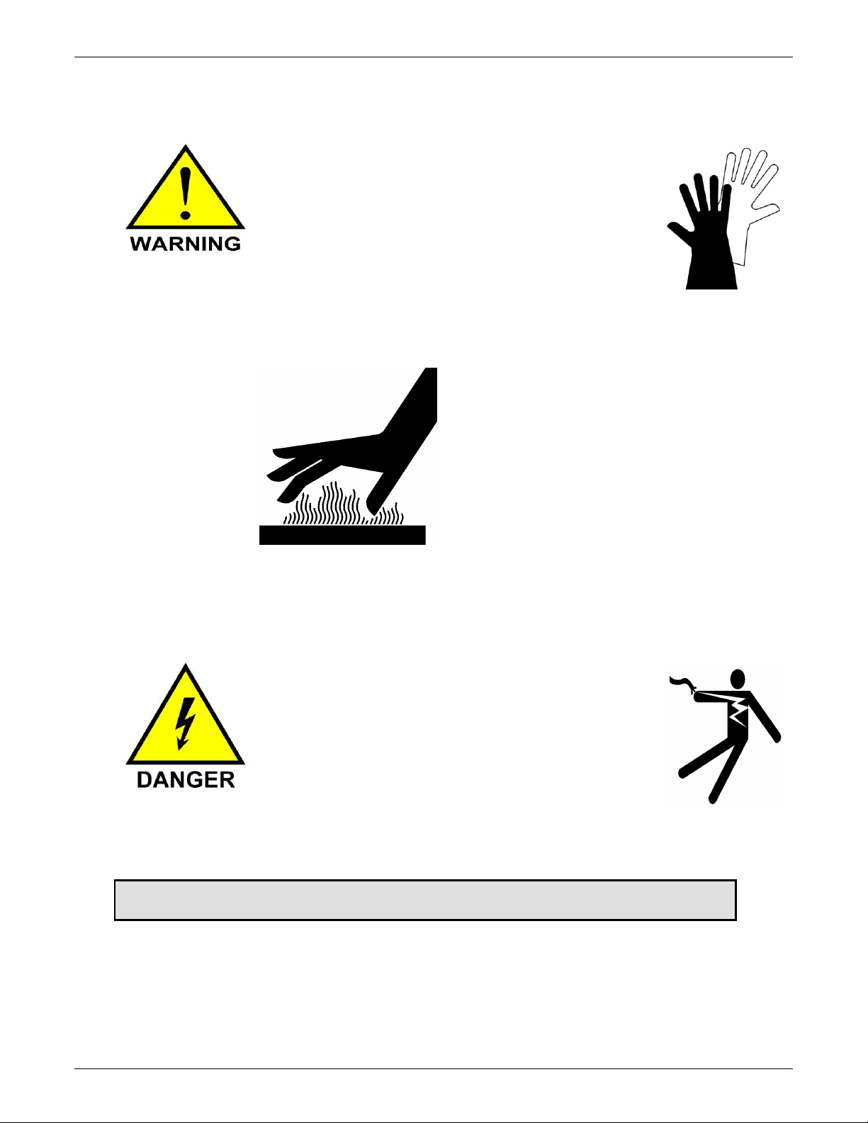
SAFETY WARNINGS
HOT SURFACES:
As with all dryers, there are HOT SURFACES to
avoid. Temperatures can reach 350F, (180C).
Typically, these surfaces are not at dangerous
temperatures, however all hot surfaces should be avoided.
Warning Label indicate:
HOT SURFACES
USE CAUTION when removing
and installing canisters.
USE GLOVES
DO NOT REACH into the dryer
enclosure.
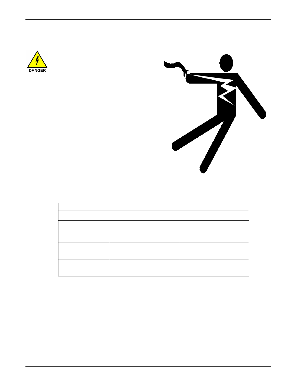
RISK OF SHOCK:
Disconnect power supply before
servicing the Dryer.
GETTING STARTED: PROCEED TO: INSTALLATION - NEXT PAGE
Maguire Products, Inc.
8
VBD - Vacuum Dryer TSC
Installation
Transport and Setup
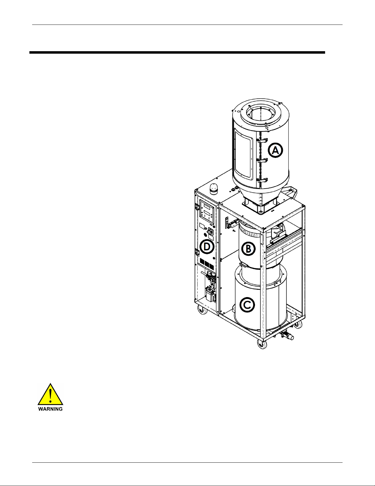
Shipment
The VBD-150 Dryer is shipped on two pallets
with 4 main sections:
(A) Heating Hopper Assembly
(B) Vacuum Chamber Assembly
(C) Retention Hopper Assembly
(D) Control Panel
Lifting and Moving components of the Dryer
Ensure your lifting equipment is rated to lift the weight of the
individual sections of the VBD-150 or VBD-300. See Technical
Documentation on page 75 for weights of the individual sections
of both the VBD-150 and the VBD-300.
Maguire Products, Inc.
9
VBD - Vacuum Dryer TSC
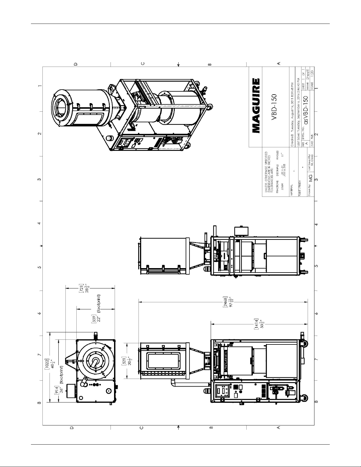
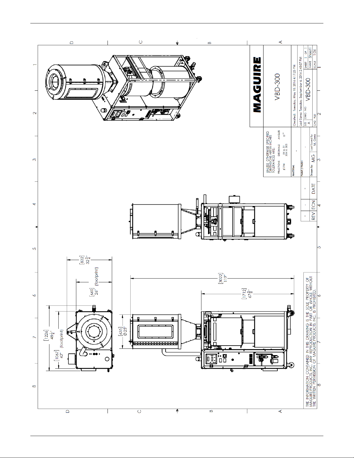
Overall layout and Dimensions
VBD-150
Maguire Products, Inc.
10
VBD - Vacuum Dryer TSC
VBD-300
Maguire Products, Inc.
11
VBD - Vacuum Dryer TSC
VBD-150 Assembly
Shipment Inventory
The VBD-150 is shipped on two pallets. One pallet holds the main body of the VBD-150 and two cardboard
boxes containing the Vacuum Chamber, the Retention Hopper, and hardware for assembly. The second
pallet holds the heating Hopper.
Hardware includes: 1 - 2" Hose Clamp, Two RTD Assemblies (RTD Sensor, wire, plug), 4 - ½" x13x1¼"
Button Head bolts, 4 - ½" Lock Nuts, 8 - ½" Star Washers.
Unpacking the VBD-150 Main Body
Remove the two boxes containing the Vacuum Chamber and Retention Hopper from the pallet.
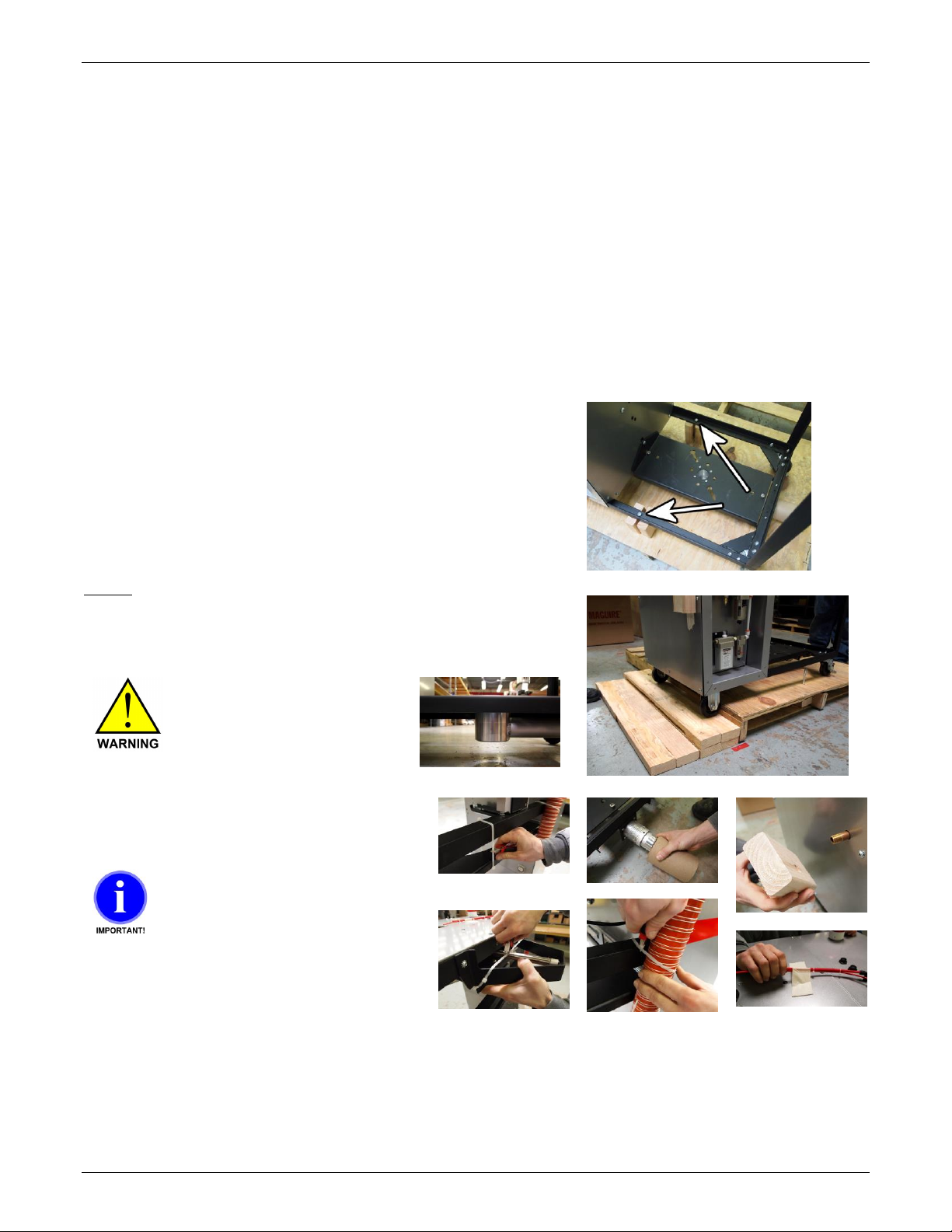
With the VBD-150 pallet on the floor, secure the wheels so that it
will not roll once it is unbolted from the pallet. Two wheels can be
locked. With the wheels secured, locate the two shipping bolts that
attach the VBD-150 to the pallet. Unbolt the upper visible nuts
from the frame and allow the bolt to drop out of the VBD-150
frame. Remove the Wood blocks. The VBD-150 is now detached
from the shipping pallet. Use caution.
Do not wheel the VBD-150 directly off of the pallet. Damage to the
VTA can occur. The VBD-150 can be gently wheeled off of the
pallet using stacked 2x4 pieces of wood. Use two or more people
to guide the Dryer off of the pallet. Make sure enough clearance is
given to the VTA.
Under the Dryer there is a
VTA. Use enough ramp
clearance to prevent contact
with the VTA below Dryer.
Remove all packing material from Dryer main
body.
When cutting the zip-tie
located at the top rear of the
dryer, hold the Vacuum tray
and lower it slowly onto load
cell. →
Maguire Products, Inc.
12
VBD - Vacuum Dryer TSC
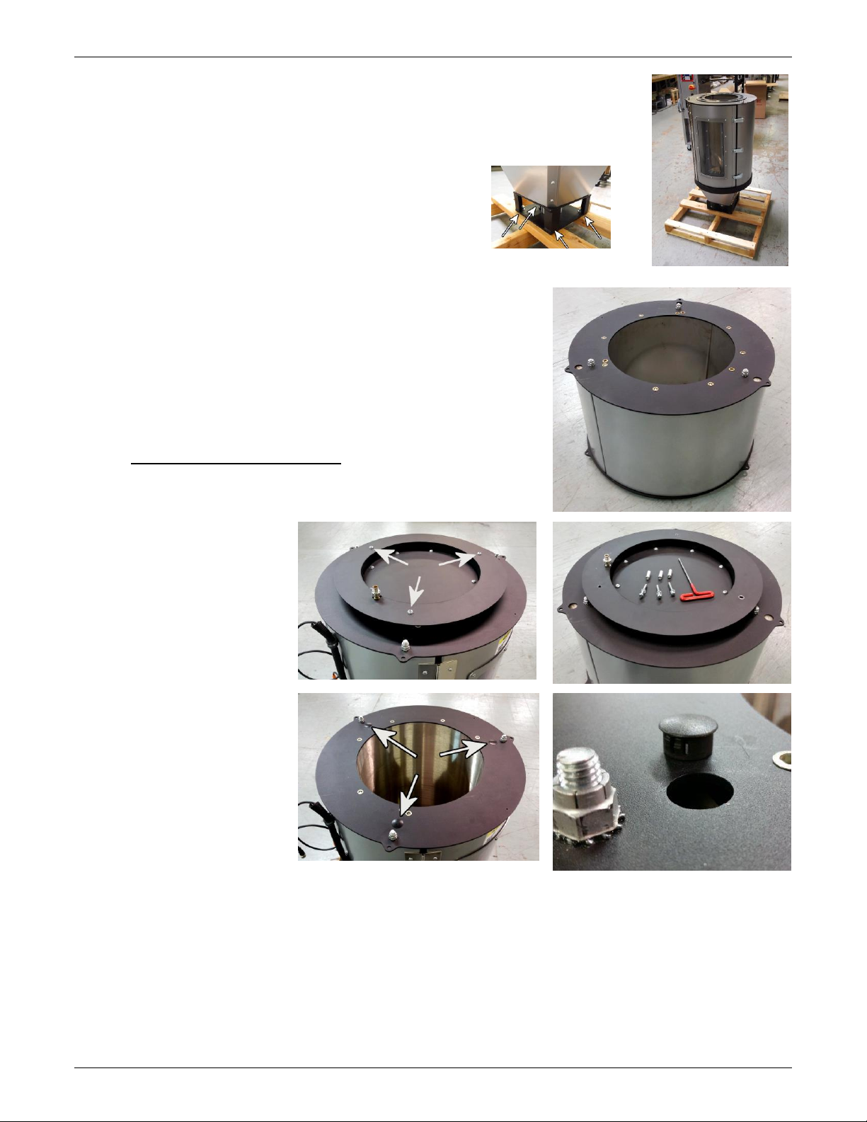
Heating Hopper Installation
The Heating Hopper is shipped on a separate pallet. The weight of the Heating
Hopper is 115 lbs (52 kg).
It is secured to the pallet with four bolts.
While holding the heating hopper securely, remove these
four bolts.
Heating Hopper Extension - OPTIONAL
The Heating Hopper Extension is used to increase heat residence time
or running at higher throughputs.
If the VBD Dryer will use a Heating Hopper Extension, it should be
installed before the Heating Hopper is installed into the VBD Dryer.
If you do not have a Heating Hopper Extension, please skip to the next
section, Attaching the Heating Hopper.
Remove Loader Adapter Plate /
Diffuser Assembly from the top
of the Heating Hopper by
removing the three 1/4-20
button head screws and
spacers. Lift the Loader
Adapter Plate off of the Heating
Hopper.
Remove the three black plastic
plugs located on the upper plate
of the Heating Hopper. See
photos.
Maguire Products, Inc.
13
VBD - Vacuum Dryer TSC
Install the Loader Adapter Plate / Diffuser Assembly onto Heating
Hopper Extension. Either open end of the Heating Hopper Extension
can be facing up, the open ends are the same.
Install Hopper Extension onto the top of the Heating Hopper, aligning
the flange bolt holes. The protruding bolts on the bottom of the
Heating Hopper Extension will insert into the holes on top of the
Heating Hopper.
Secure the Heating Hopper Extension
onto the Heating Hopper at the flange
using the supplied 1/4-20 button head
screws and Nyloc nuts.
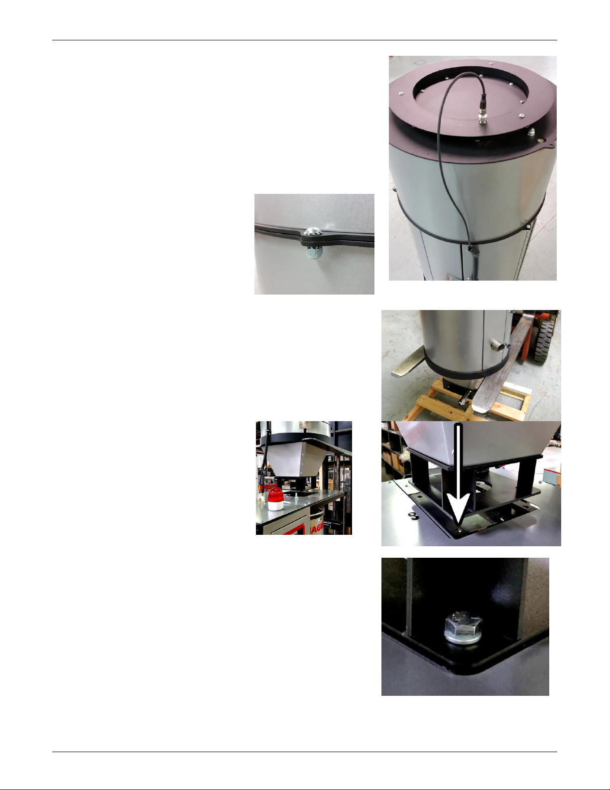
Secure the RTD cable to the RTD located
on the Loader Adapter Plate / Diffuser
Assembly.
Attaching the Heating Hopper
A forklift can be used to raise the heating hopper onto the VBD-150
main body. Lifting points are located below on the lower black steel
ring as shown in photo on right.
Install the Heating Hopper so that the Heating Hopper Access Door
is facing the front of the Dryer, the same side as the Control Panel.
Lower the Heating Hopper onto the VBD-
150. Line up the Heating Hopper bolt
holes with the bolt holes on the VBD-
150. Once lowered the Heating Hopper
can be carefully moved to line up the bolt
holes.
Install the four ½”-13 bolts as follows:
Each ½”-13 bolt will receive a ½” lock washer below the head.
Maguire Products, Inc.
14
VBD - Vacuum Dryer TSC
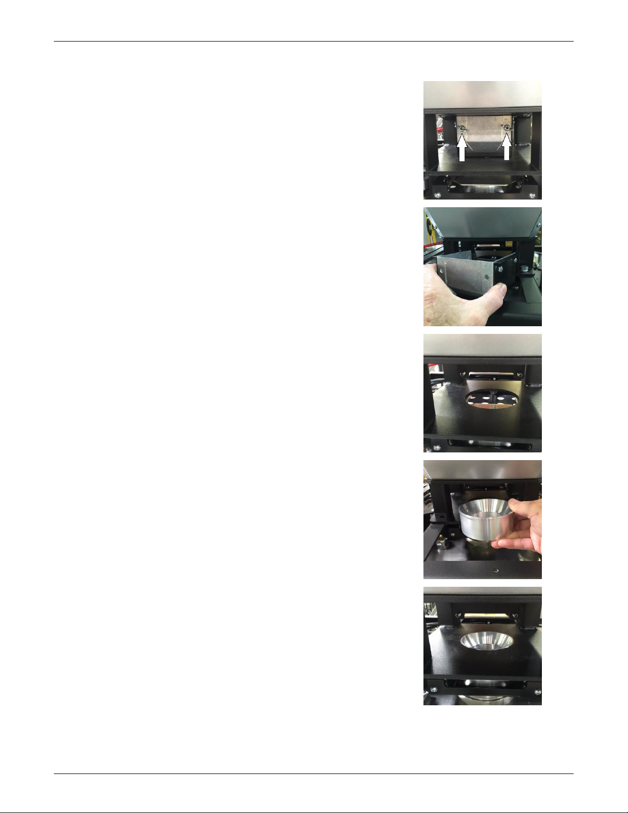
VBD-150 Heating Hopper Install - Drop Tube
1. At the bottom of the heating hopper, remove the 2
wing nuts holding the Vacuum Chamber fill valve
recollector hopper.
2. Remove the Vacuum Chamber fill valve hopper.
3. Install the supplied aluminum Drop Tube. Packed
separately. See next photo.
4. Install Drop Tube in large hole in bottom of hopper
frame.
5. Drop Tube installed.
6. Reinstall the slide gate fill valve recollector hopper. Tighten wing nuts. Finish the Hopper
installation by hooking up air lines and hoses per the manual.
Maguire Products, Inc.
15
VBD - Vacuum Dryer TSC
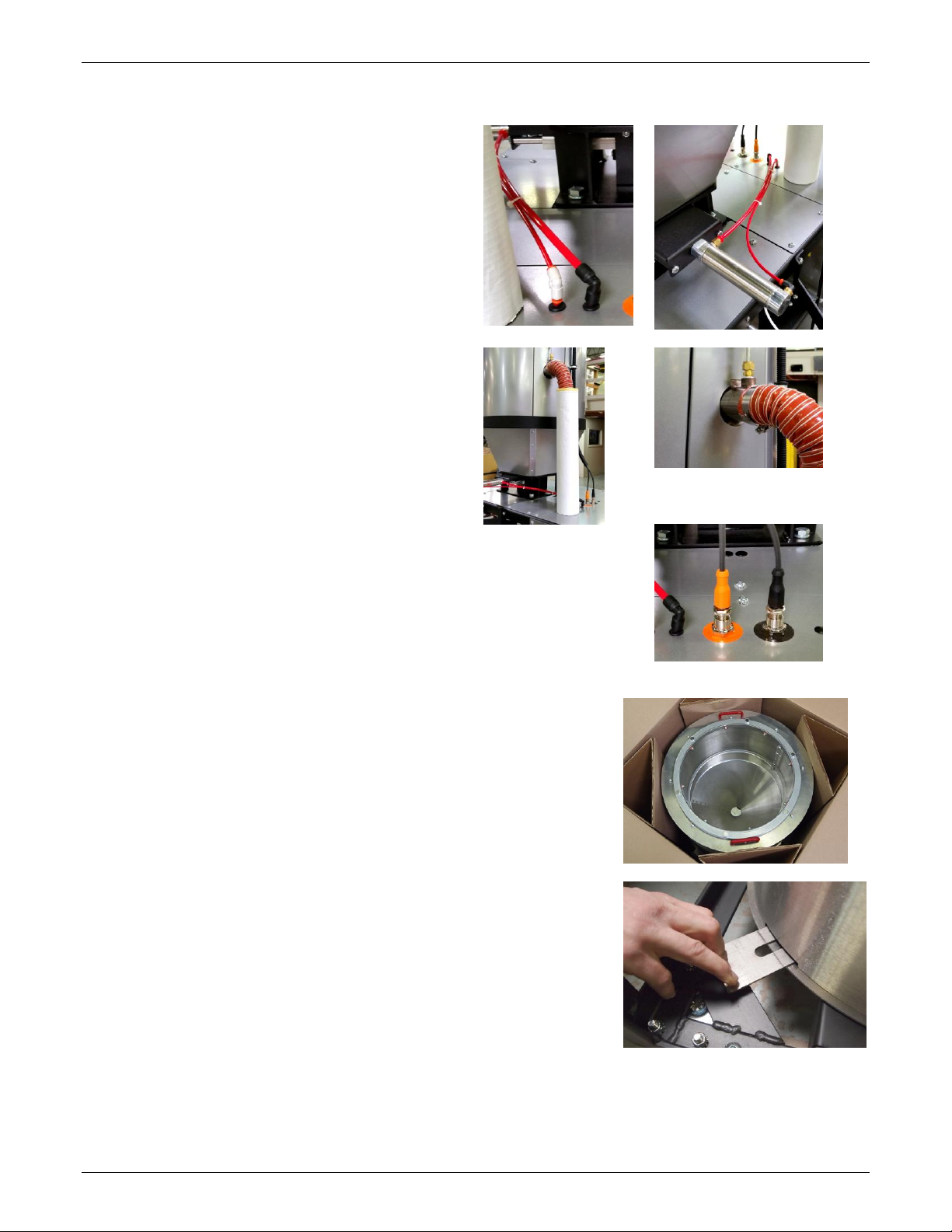
Install Connections
Attach the Heating Hopper Slide Gate air
lines.
The two air lines that connect the Heating Hopper Air
cylinder to the VBD-150 are different sizes to prevent
an incorrect connection.
Attach the Heating Hopper Hose
Using the 2" hose clamp, attached the red heating
hose to the Heating Hopper.
Attach the RTD Plugs
The RTD plugs are different sizes and will only install on the correct outlet.
Installing the Retention Hopper
Unbox the Retention Hopper. The Retention Hopper is identified by the
red handles located on the top of the hopper (the Vacuum Chamber has
red handles on the upper sides).
Close the slide-gate to allow the Retention Hopper to seat down onto
the base of the VBD-150. Once seated open the slide-gate to allow
material to flow.
Install the Retention Hopper so that the Retention Hopper manual slidegate is located at the forward right corner of the Dryer.
Maguire Products, Inc.
16
VBD - Vacuum Dryer TSC
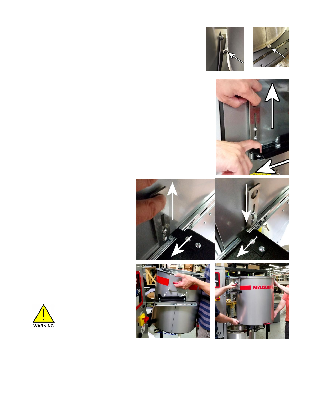
At the base of the Retention Hopper are two slots that must be aligned
with the locator bolts.
Once the locator bolts are aligned, press in the slide-gate to lock the
Retention Hopper in place and open the base for material flow.
Installing the Vacuum Chamber
Unbox the Vacuum Chamber.
Lift the Slider Lock located on the right side of the VBD-150 cabinet.
Lock Slider into Open Position
While holding the Slider Lock up, pull the
Vacuum Chamber slider out. When the
slider is fully extended, release the Slider
Lock, which will lock behind the retaining
plate at the very rear of the opened slider
locking the slider into the fully extended
position (see photos below).
Rest the Vacuum Chamber onto the fully
extended Sliders. The Vacuum Chamber
has three resting pins. Orient the side with
two resting pins on the left Slider rail.
Two people are required to
lift the VBD-300 Vacuum
Chamber.
Maguire Products, Inc.
17
VBD - Vacuum Dryer TSC
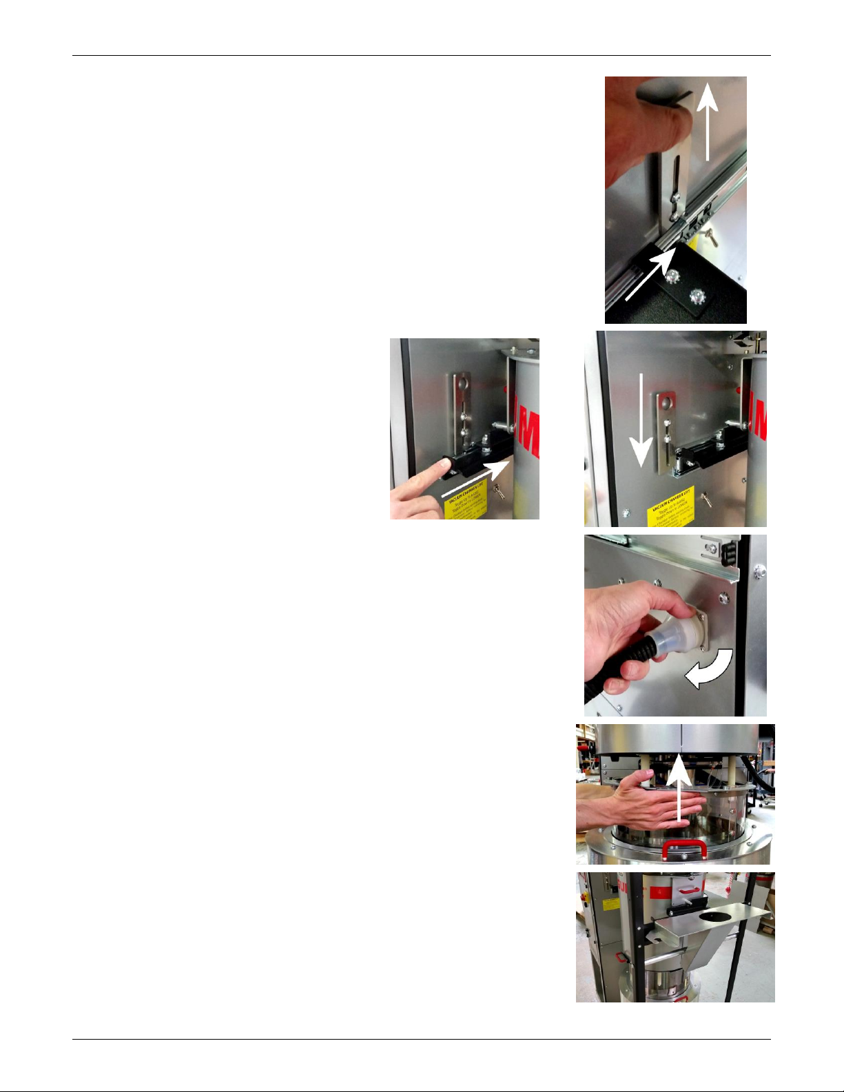
Unlock Slider to Close
Hold the Slider Lock up and push the Vacuum Chamber Slider in until it
clears the retaining plate. Release the Slider Lock and continue pushing
the Vacuum Chamber Slider in.
Push the Slider rails and Vacuum
Chamber back into the Dryer until the
Slider Lock falls into place in front of the
Vacuum Chamber Slider, locking the
Vacuum Chamber Slider into the operating
position.
Connect the air lines. Rotate the locking ring fully clockwise to secure the
air connection.
Slide the Retention Hopper sealing collar up so that the magnets engage
onto the bottom of the Vacuum Chamber.
Storage of the Optional Heating Hopper Dump Chute
The heating Hopper Drain Chute (optional) should be stored on the right of
the dryer hanging on the black frame. See photo.
Maguire Products, Inc.
18
VBD - Vacuum Dryer TSC
Dryer External Connections
Once assembled, installation requires connection of: pneumatic air line, electrical, intake and output material
lines.
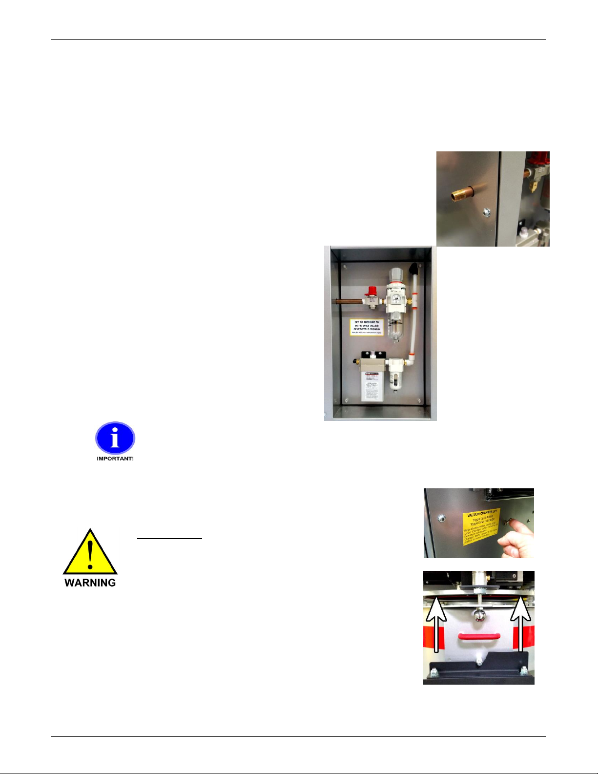
Compressed Air Connection
Connect an air supply to the air regulator’s IN port using a female 1/4” NPT
pipe fitting.
An operating air pressure of 80 psi (5.5 bar) while the vacuum
generator is running is required for proper operation of the Dryer.
Setting the air pressure to 85 psi while the machine is idle will usually
attain the desired 80 psi while the vacuum generator is running.
If your air supply has oil in it, add an oil separator
(coalescing filter). Oil in the air will combine with dust drawn from the
Vacuum Chamber forming a paste inside the vacuum generator. It
will stop working and require cleaning.
Observe the air pressure gauge to be sure the pressure maintains 80
psi (5.5 bar) while the vacuum generator is running as you check and
adjust the regulator. If pressure drops below 80 psi, adjust the
regulator. If the pressure cannot be maintained at 80 psi (5.5 bar) while
the vacuum generator is running, then the air supply line is not
adequate.
Do not supply Dryer with a lubricated air supply. Damage
to Dryer may result. Use only a clean, dry, oil-free air
supply.
Pinch Hazard - Keep fingers clear of seal deck, the
mating surface above the Vacuum Chamber seal.
When air pressure is turned on and the Vacuum
Chamber Lift Switch is flipped up, air cylinders lift the
Vacuum Chamber off of the slider rails and up to the
seal deck closing the gap between the top of the
Vacuum Chamber and the seal deck.
KEEP FINGERS CLEAR
Maguire Products, Inc.
19
VBD - Vacuum Dryer TSC
Electrical Connection
RISK OF INJURY! Only
qualified technicians
should make electrical
connections.
Connect Main Power
The electrical cable located on
the left side of the Dryer on the
power box supplies the power
to the Dryer. Within the cable
are four wires. Three of the
wires are black and labeled with
a number: 1, 2, and 3. The
fourth wire is a green/yellow
wire and is the ground wire.
Connect power to a properly fused disconnect.
VBD Fuse / Circuit Breaker Rating Table
Protect the unit with fuses or circuit breakers at the amp ratings shown below:
AMPS
Voltage
VBD-150
VBD-300
240
35
-
400
25
35
480
20
30
575
20
25
See the High Voltage Wiring Diagram section starting on page 78.
Maguire Products, Inc.
20
VBD - Vacuum Dryer TSC
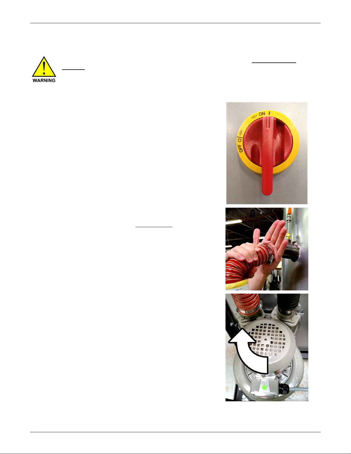
Confirm Correct 3-Phase Electrical Connection
THREE PHASE Unit - CONFIRM proper 3-Phase power connection prior to loading
material. Failure to confirm proper 3-phase connection can result in reversed blower
rotation and damage to blower if the blower sucks in material from heating hopper rather
than blow heated air into heating hopper.
To confirm proper 3-phase connection following these instructions:
Turn power on using main power switch.
There are two methods to confirm proper 3-phase
connection:
Incorrect 3-phase connection will result in reversed
blower rotation. Both methods for checking correct
3-phase connection involve testing the blower
rotation.
Method one requires the disconnecting the 2-inch hot
air hose from the heating hopper and manually
turning on the blower. The air from the blower should
blow out of the 2-inch hose. Air should not suck into
the hose. If air does not blow out and sucks in, the 3phase connection is NOT correct.
Method two requires the removal of the left side
panel to view the blower and confirm blower rotation
on power up. Rotation must be clockwise as
indicated by the red arrow.
1. From the Main Screen press
Manual Operations.
2. Press Blower Test.
3. Press the Blower button once to turn ON the
Blower. Press again to turn OFF.
Maguire Products, Inc.
21
VBD - Vacuum Dryer TSC
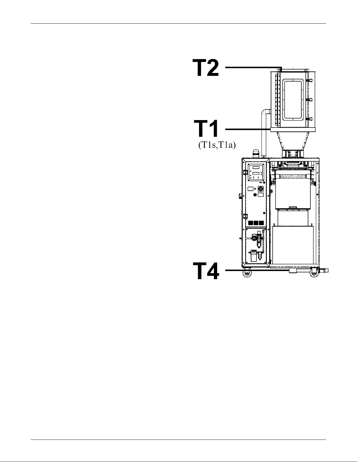
Dryer Overview
T2 – Heating Hopper Outlet Temperature
T1 – Heating Hopper Inlet Temperature
T1s – Heating Hopper Air Inlet
Temperature Setting
T1a – Heating Hopper Air Inlet
Temperature Actual
T4 – Material Outlet Temperature (optional)
Maguire Products, Inc.
22
VBD - Vacuum Dryer TSC
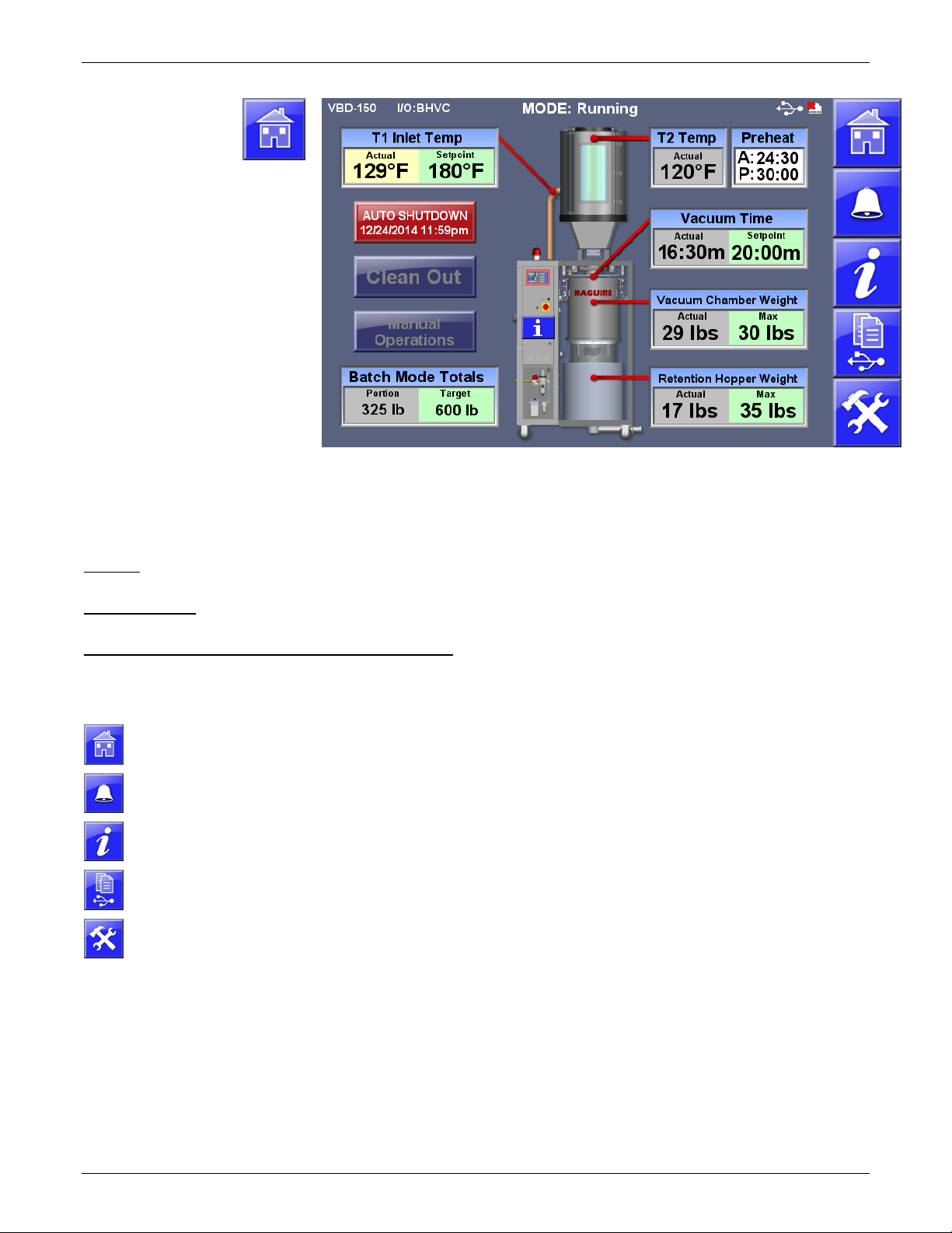
Home Screen
Overview
Preheat – Preheat Time Actual and Preheat Time Setpoint. Touch to adjust.
Info (i) - Access to advance information.
Additional information can be accessed by touching the Heating Hopper, Vacuum Chamber
and the Retention Hopper.
Shown with enabled options: Auto
Shutdown, Batch Mode, and
Preheat.
T1 Actual - Actual Heating Hopper
inlet air temperature
T1 Setpoint - Heating Hopper inlet
air temperature Setpoint. Touch to
adjust.
T2 Temp – Actual Heating Hopper
temperature
Vacuum Time – Vacuum Time
Actual and Vacuum Time Setpoint.
Touch to adjust.
Vacuum Chamber Weight
Vacuum Chamber Actual and
Maximum Weight
Retention Hopper Weight
Actual and maximum weight
Title Bar - Located across the top of the screen, the title bar displays Model, ID, I/O status, current operating mode, date and time,
Ethernet and USB status.
Navigation Menu - Located along the right side of the screen, these buttons allow quick navigation to frequently used and top level
screens. The middle three buttons are soft buttons that can be changed or removed.
Start / Shutdown (Auto Shutdown shown above) Button - Main Start Stop Control Button of the Dryer.
Navigation Menu
Home Screen
Pressing the Home Screen button from any other screen will return the operator to
the main Home Screen.
Alarm and Event
Alarm and Event Log displays a history of alarms and other events with a date and
time stamps and description.
Info Screen
System Information including firmware versions, IP and MAC address and machine
operating tags.
Print Center
A menu screen of print related options including Totals, Parameters, Alarm History,
Events, Cycle History, Diagnostics. See page 62.
Setup Login
Password protected access to advanced Dryer and System configuration
information. See Page 35.
Run Dryer - See page 23
Run Dryer in Batch Mode – See page 48
Clean Out – See page 58
Manual Operations - See page 30
Maguire Products, Inc.
23
VBD - Vacuum Dryer TSC
Startup and Operation
This section will help you understand what the dryer is doing during operation from a cold start. There are 3
concurrent operations. Heating, Vacuum and, Retention. Cold startup begins with Preheat. Preheat only
occurs before the first cycle of the dryer’s initial startup, otherwise each cycle begins with material heating.
The vacuum operation pulls and holds a vacuum on the material for at least the Vacuum Time Set-point (or
longer if material remains in the Retention Hopper). The Retention operation holds the dried material in the
Retention Hopper. If equipped with the optional membrane air dryer, the material will be blanketed with hot
dry air until it is conveyed away.
Important: Inspect the VBD, verify that machine is clear of all material from heating hopper, Vacuum
Chamber and Retention Hopper. To facilitate a Clean Out, use the Clean Out function accessible from the
home screen.
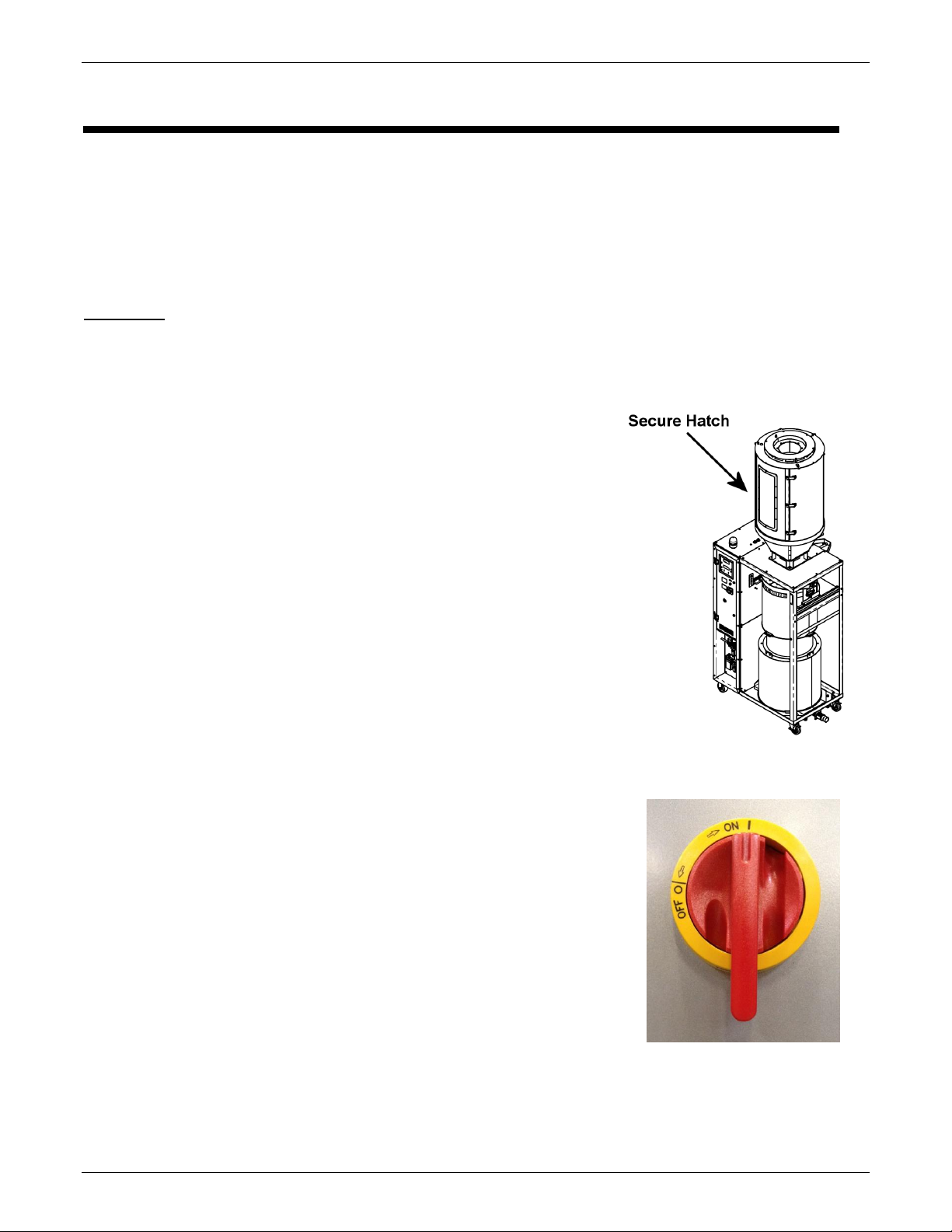
Startup and Operation Instructions
1. ENSURE HATCH IS CLOSED. There is a hatch located on the
upper Heating Hopper. Ensure all 3 latches are closed. Also,
be sure the removable Lower Retention Hopper is in place.
2. Load material into the Upper Heating Hopper. Wait for the
Heating Hopper to fill with material before starting the Dryer.
3. Turn on Main Power by rotating the 25 AMP Main Disconnect
Handle to the Red ON position. This powers up the VBD-150
Dryer.
On initial power up of the VBD, the Control Panel powers ON
automatically. If the main power is ON but the Control Panel is
OFF, press and hold the Red Power Button located on the
Control Panel for 2 seconds. (Note: The VBD’s Control Panel
can be powered OFF without powering down the Main Power
by pressing and holding the Red Power button for 4 seconds).

Maguire Products, Inc.
24
VBD - Vacuum Dryer TSC
4. On the Home Screen:
T1 Inlet Temp Setpoint – This is heat hopper inlet temperature. By
the end of the preheat cycle time, all material in the Heating Hopper
will be heated to this temperature. By default, the Setpoint
temperature is set to 150°F. See Recommended Drying
Temperatures on page 29 for general temperature recommendations
or contact the material manufacturer.
Preheat Time – This is the duration of heating from a cold start.
Vacuum Time – This is the minimum duration of a vacuum cycle.
Actual vacuum cycle times will vary according to the throughput. The
default vacuum time is 20 minutes. In the vast majority of drying
operations, this time is adequate and does not need to be adjusted.
Special circumstances may require different vacuum times. Please
consult Maguire Dryer Technical Support for additional information.
Press the setpoint field to adjust the setting. Use the on-sceen
keypad to enter the setpoint and press the green check to complete
the setting adjustment.
5. Press the START button to start the dryer.
4. The display will show that the dryer is running in PREHEAT
mode and display the following:
T1 Actual - Actual Heating Hopper inlet air temperature
T1 Setpoint - Heating Hopper inlet air temperature Setpoint.
T2 Temp – Actual Heating Hopper temperature
Vacuum Time – Vacuum Time Actual and Vacuum Time Setpoint.
Vacuum Chamber Weight - Vacuum Chamber Actual/Maximum Weight.

Maguire Products, Inc.
25
VBD - Vacuum Dryer TSC
What is happening when the dryer is running:
During the Pre-heat operation material in the heating hopper is brought up to temperature (T1s).
Preheat time is determined by the specified Preheat Time on the Pre-Start screen (timed preheat,
default 35 minutes) or by the Preheat Setup Auto option, which sets an inlet to outlet temperature delta
and a minimum preheat time.
After pre-heat, approximately one third of the material in the heating hopper is dispensed into the
vacuum chamber, and the first vacuum cycle begins. Each vacuum cycle has a minimum vacuum time,
set on the Pre-start screen, or the main run screen (VTs). (default is 20 minutes).
The loader loads the Heating Hopper with new material as the Vacuum Chamber receives the heated
material and heating cycle begins concurrent to vacuum cycle (the first vacuum cycle is timed). The new
batch of material in the upper portion of the heating hopper will take less time to heat. Minimum time in
the heating is dictated vacuum time.
After first vacuum cycle, material is then dispensed into retention hopper ready for use. Material in the
retention hopper is blanketed with dry air (if equipped with optional membrane air dryer).
The rate of consumption of dried material from the retention hopper ultimately dictates the amount of
time that the material will be preheated and under vacuum. Examples: If it takes 25 minutes to deplete
the retention hopper, the vacuum cycle will run past its 20 minute setpoint (pre-start screen) to 25
minutes. This is normal operation. However if the retention hopper is depleted in 15 minutes and the
vacuum time is set to 20 minutes, there will be a 5 minute window where no material is available. This
indicates that the throughput of the dryer has been exceeded. If the Throughput Alarm is enabled
(Alarm Setup), a Throughput Alarm (Alarm Code 20) will be triggered.
Maguire Products, Inc.
26
VBD - Vacuum Dryer TSC
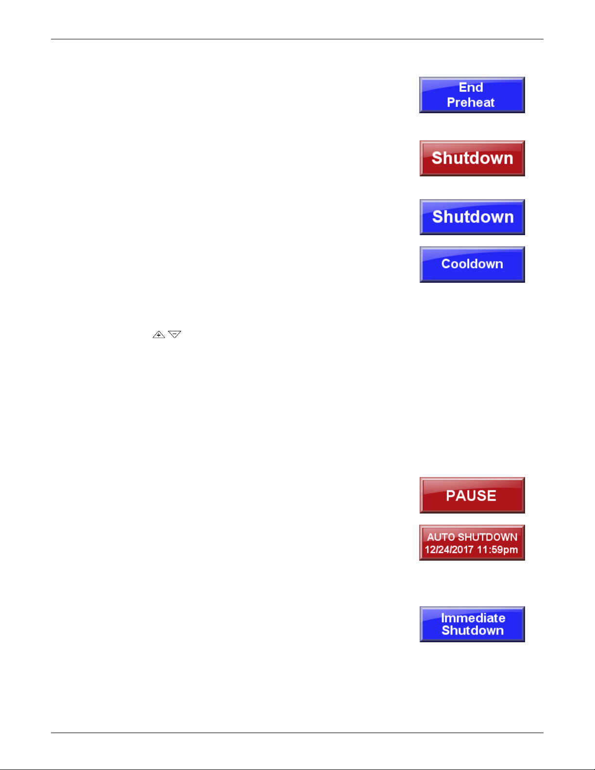
End Preheat, Shutdown, Auto Shutdown, Immediate Shutdown and Pause
End Preheat - (shown only if in a preheat cycle)
Skips the preheat allowing material to immediately pass down to the
Vacuum Chamber (example: material has already been heated and
dryer has been taking offline briefly and powered back on).
At any point during the preheat cycle or standard operation (operation
after initial preheat cycle), pressing the red Shutdown button will bring
up the Shutdown Options screen with the following shutdown options:
Shutdown – Shutdown will continue to run the dryer and process the
material in the Vacuum Chamber and the Retention Hopper until they
are empty. Selecting Planned Shutdown will display the Cooldown
option.
Cooldown (ON/OFF) – When enabled Cooldown will gradually
bring down the temperature of the material in the heating hopper to
the specified temperature (Cooldown Temp) over the specified time
period (Cooldown Time).
To adjust the Cooldown Temperature and Cooldown Time use the
arrow buttons to adjust the setting. Press ENTER to
advance through the digits and to complete the setting adjustment.
Press the Shutdown button to shutdown.
Pressing the red power button during a Planned Shutdown will
display the Immediate Shutdown Screen allowing initiation of an
immediate shutdown of the dryer.
Pause – Press the Vacuum Chamber will display the Vacuum
Chamber Setup screen. Pause is the red button at the bottom of the
screen. Pauses the vacuum timer indefinitely. To restart after a
pause, press RESUME.
Auto Shutdown – Initiates a shutdown (see above) at specified date
and time. For further explanation on how to set the Auto Stop date and
time see page 27.
Immediate Shutdown – Fast but controlled shutdown of the heater,
blower, the vacuum system and the purge system.
Cancel - Exits the shutdown prompt screen, doing nothing.
Maguire Products, Inc.
27
VBD - Vacuum Dryer TSC
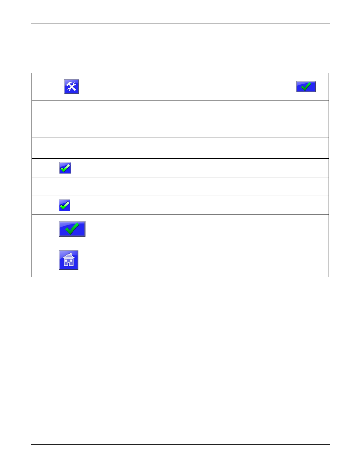
Auto-Stop Setup
Auto-Stop initiates a shutdown at a specified time on specific days if the week.
To enable and configure Auto-Stop follow the steps below.
Press
Display will prompt for a password. (default: 22222)
Then press:
Press
Dryer Configuration
Display will show the Dryer Configuration categories.
Press
Auto-Stop Setup
Display will show the Auto-Stop screen.
To Enable Auto-Stop:
Press
Auto-Stop Enabled
to enable Auto-Stop. Display will show Auto-Stop scheduling.
Press
Schedule
Set the time of day Auto-Stop should occur.
Press
to select the days of the week Auto-Stop should occur.
Press
to save the Auto-Stop settings.
Press
the Home Button to return to the Home Screen.

Maguire Products, Inc.
28
VBD - Vacuum Dryer TSC
Advanced Information
Pressing on the Home Screen will display additional information such as readings of all RTD
thermometers, vacuum time elapsed, absolute pressure in the Vacuum Chamber, blower drive frequency.
T1 Actual - Actual Heating Hopper inlet air temperature.
T1 Setpoint - Heating Hopper inlet air temperature Setpoint.
Heat Hopper - Heating Percent (%) output.
T2 Temp – Actual Heating Hopper temperature
Fill Info – The desired weight of material to be dispensed into the Vacuum Chamber.
Bulk Density - Bulk density of material in either pounds per cubic foot or kilograms per liter.
Cycle Count - Total number of cycles since start button was pressed.
Cycle Time - Total time to process a completed batch of dry material.
Valve Timing - Fill - Total time to fill the Vacuum Chamber.
Valve Timing - Dump - Total time to dump the Vacuum Chamber.
Totalizer - Calculated total of all cycles since last clear of totals.
Thruput - Calculated throughput, weight per hour.
Vacuum - Vacuum Chamber Actual Weight
Retention - Current material weight in Retention Hopper.
Residence – Actual Vacuum Time.
Maguire Products, Inc.
29
VBD - Vacuum Dryer TSC
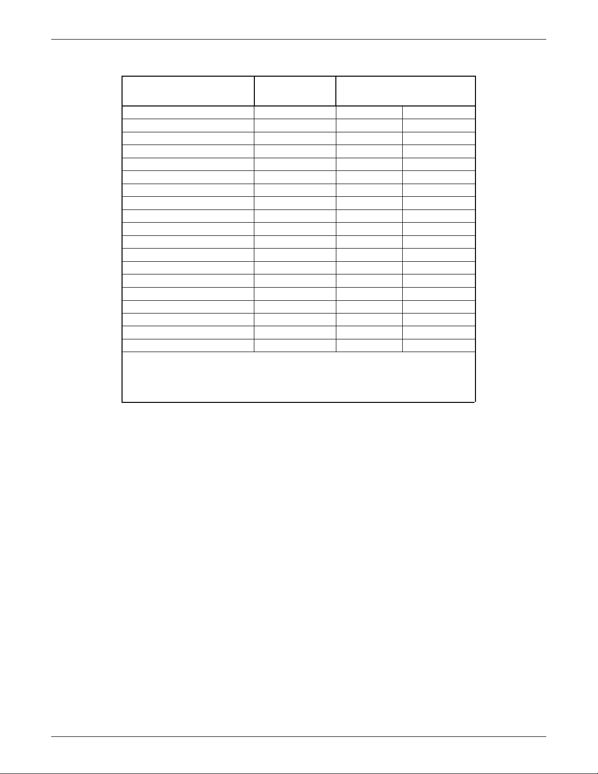
Recommended Drying Temperatures
MATERIAL
FINAL
MOISTURE % *
DRYING TEMPERATURE** ºC
ºF
ABS
0.10
80 - 85
180 – 190
ABS/PC
0.02
100
210
LCP
0.02
150
300
PA
0.20 - 0.10
80 - 85
180 – 190
PBT
0.02
120
250
PC
0.02
125
250
PC/PBT
0.02
125
250
PEEK
0.20 - 0.10
150
300
PEI
0.02
150
300
PES
0.05 - 0.02
150
300
PET (Molding Grade)
0.010
150-180
300-350
PET (Preform, Extrusion)
0.005
150-180
300-350
PMMA (Acrylic)
0.02 - 0.04
79
175
POM (Acetal)
0.20 - 0.10
80 - 110
180 – 230
PPO
0.02
100 - 120
210 – 250
PPS
0.02
150
300
PUR
0.02
125 - 140
260 – 280
PSU
0.02
150
300
SAN
0.20 - 0.10
80
180
* Final moisture content as recommended by the raw material manufacturer.
** Drying temperature as recommended by the material manufacturer.
Drying is accomplished when all material reaches the proper temperature, and is
then placed under sufficient vacuum for a sufficient period of time.
Measurement of moisture content of material, both prior to and after drying, is
accomplished by using a moisture analyzer.
Maguire Products, Inc.
30
VBD - Vacuum Dryer TSC
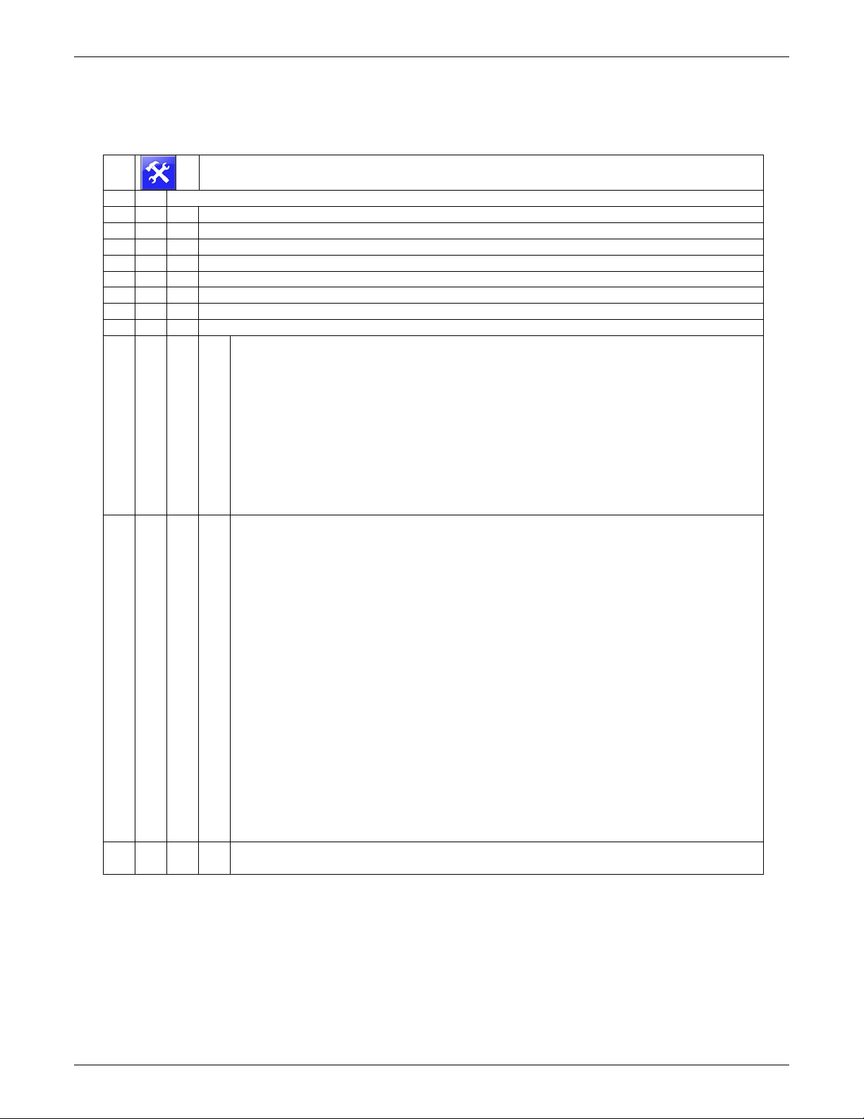
Setup Menu Map - Brief Explanation
This section contains a brief explanation of the Setup menu. For detailed information see Setup Menu Full
Explanation starting on page 35.
► Setup (password protected) – Settings and Options Menus
► Dryer Configuration - Dryer specific settings
►
Alarm Setup – Enable or disable various alarms.
►
Auto-Stop Setup - Scheduling Auto-Stop of the dryer.
►
Dry Purge Setup - Configuration of dry purge.
►
Preheat Setup - Configuration of Preheat.
►
Auto-Start Setup - Scheduling Auto-Start of the dryer.
►
Convey Setup - Configuration of material convey and loaders.
►
Load-cell Setup - Loadcell calibration, zero and full calibration.
►
Parameters - Operation Parameters
►
Blower
• BDT - Blower Delay Time (Seconds)
• BLF - VFD Low Limit
• BHF - VFD High Limit
• BDF - VFD Frequency
• BZL - VFD Zero Level
• BLA - VFD Level Adjustment
• BHT - VFD Heat Throttle
• BAC - VFD Air Flow Cutback
• BTC - VFD Temperature Cutback
• BTA - VFD Throttle Adjustment
►
Heater
• PTS - Preheat Temperature Setting
• PHT - Preheat Time
• PTD - Preheat Target Delta
• RTS - Run Temperature Set-Point
• PT1 - PD Loop Proportional
• DT1 - PD Loop Derivative
• UT1 - PD Loop Update Time
• OT1 - Heat1 Over-Target Alarm
• NH1 - Heat1 No Heat Alarm
• SO1 - Heat1 Set-Point Off. Percent
• MP1 - Heat1 Max Percent
• RO1 – Heat1Restart Offset
• MAX - Max Temp Set-Point
• ESL - Energy Savings Limit
• ESD - Energy Savings Differential
• EST - Energy Saver Time
• RMP - Temperature Ramp Settings
• CTM - Cool-Down Temperature
• CTR - Cool-Down Timer
►
System
• ELT - Event Logging Time
 Loading...