


MAGUIRE PRODUCTS INC.
VBD-150® Vacuum Dryer
INSTALLATION • OPERATION • MAINTENANCE
Rev. August 31, 2016
VBD-150®
Maguire Vacuum Dryer
Copyright © Maguire Products, Inc. 2016
®

V
BD® - Vacuum Dryer®
Maguire Products, Inc.
2
Rev. August 31, 2016 – VBD-150

V
BD® - Vacuum Dryer®
Maguire Products, Inc.
VBD-150® - Vacuum Dryer ®
Copyright © 2016 Maguire Products Inc.
The information contained within this manual including any translations thereof, is the property of
Maguire Products Inc. and may not be reproduced, or transmitted in any form or by any means
without the express written consent of Maguire Products Inc.
To every person concerned with use and maintenance of the Maguire VBD-150® it is
recommended to read thoroughly these operating instructions. Maguire Products Inc. accepts no
responsibility or liability for damage or malfunction of the equipment arising from non-observance
of these operating instructions.
To avoid errors and to ensure trouble-free operation, it is essential that these operating
instructions are read and understood by all personnel who are to use the equipment.
Should you have problems or difficulties with the equipment, please contact Maguire Products
Inc. or your local Maguire distributor.
These operating instructions only apply to the equipment described within this manual.
Manufacturer’s Contact Information
Maguire Products Inc.
11 Crozerville Road
Aston, PA. 19014
Phone: 610.459.4300
Fax: 610.459.2700
Website: http://www.maguire.com
Email: info@maguire.com
Rev. August 31, 2016 – VBD-150
3

V
BD® - Vacuum Dryer®
Accuracy of this Manual
We make every effort to keep this manual as correct and current as possible.
However, technology and product changes may occur more rapidly then the
reprinting of this manual. Generally, modifications made to the dryer design or to
the operation of the software are may not reflected in the manual for several
months. The date at the footer of this manual will indicate approximately how
current this manual is. Likewise, your Dryer may have been produced at an
earlier time and the information in this manual may not accurately describe your
Dryer since this manual is written for the current line of Dryers in production (as of
the date in the footer). We always reserve the right to make these changes
without notice, and we do not guarantee the manual to be entirely accurate. If you
question any information in this manual, or find errors, please let us know so that
we may make the required corrections or provide you with accurate information.
Additionally we will gladly provide you with an updated copy of any manuals you
need at any time. We welcome comments and suggestions on ways we can
improve this manual.
For additional information, or to download the latest copy of this manual or any
other Maguire manual, please visit our website or contact us directly.
On the Web at: www.maguire.com
Maguire Products Inc.
Main Headquarters
11 Crozerville Road
Aston, PA 19014
Tel: 610.459.4300
Fax: 610.459.2700
Email:
info@maguire.com
Maguire Products, Inc.
Maguire Europe
Tame Park
Tamworth
Staffordshire
B775DY
UK
Tel: + 44 1827 265 850
Fax: + 44 1827 265 855
Email:
info@maguire-europe.com
Maguire Products Asia PTE LTD
15 Changi North Street 1
#01-15, I-Lofts
Singapore 498765
Tel: 65 6848-7117
Fax: 65 6542-8577
magasia@maguire-products.com.sg
Please e-mail comments and suggestions to: support@maguire.com
Maguire Italy
Via Zancanaro 40
35020 Vigorovea (PD)
Tel: +39 049 970 54 29
Fax: +39 049 971 18 38
Email:
info@maguire-italia.it
4
Rev. August 31, 2016 – VBD-150

V
BD® - Vacuum Dryer®
Table of Contents
INSTALLATION
VBD-150 Dryer Assembly
Dryer Connections
Compressed Air Connection 14
Electrical Connection
Dryer Overview
Operating Station Overview
Controller Overview
Description of Menu Options 25
Setup Menu Options Explained 27
Parameters Explained 32
Changing Parameters
Batch Mode
Communication Setup
Operation
Startup and Operation 19
Recommended Drying Temperatures
Maintenance
Loadcell Calibration
Cleanout Procedure
Vacuum Chamber Removal
Replacing the Vacuum Chamber Flange Seal
Drain and purge Air Filter / Regulator 43
Air Pressure Adjustments
Replacing the Vacuum Chamber Fill Valve Seal
Logs and Print Outputs
Alarms - Cause and Solution
Dryer Firmware Updates
Maguire Products, Inc.
8
10
14
14
17
18
18
40
41
42
19
24
43
43
44
47
49
52
55
60
64
69
General Information 70
Technical Specifications 70
Theory of Operation / Performance 71
Warranty
Diagrams
Recommended Spare Parts List
Bookmark not defined.
Technical Support / Contact Information
72
73
Error!
84
Rev. August 31, 2016 – VBD-150
5

V
BD® - Vacuum Dryer®
Warranty – Exclusive 5-Year
MAGUIRE PRODUCTS offers THE MOST
COMPREHENSIVE WARRANTY in the plastics
auxiliary equipment industry. We warrant each
MAGUIRE VBD – Vacuum Dryer manufactured by us to
be free from defects in material and workmanship under
normal use and service; excluding only those items
listed below as 'excluded items'; our obligation under
this warranty being limited to making good at our
factory any Dryer which shall, within FIVE (5) YEARS
after delivery to the original purchaser, be RETURNED
intact to us, transportation charges PREPAID, and
which our examination shall disclose to our satisfaction
to have been thus defective; this warranty being expressly in lieu of all other warranties
expressed or implied and of all other obligations or liabilities on our part, and MAGUIRE
PRODUCTS neither assumes nor authorizes any other persons to assume for it any
other liability in connection with the sale of its Dryers.
This warranty shall not apply to equipment repaired or altered outside MAGUIRE
PRODUCTS INC. factory, unless such repair or alteration was, in our judgment, not
responsible for the failure; nor which has been subject to misuse, negligence or
accident, incorrect wiring by others,
or installation or use not in accord with instructions furnished by
Maguire Products, Inc.
Our liability under this warranty will extend only to equipment that is returned to our
factory in Aston, Pennsylvania, PREPAID.
Please note that we always strive to satisfy our customers in whatever manner is
deemed most expedient to overcome any problems they may have in connection with
our equipment.
Maguire Products, Inc.
6
GETTING STARTED:
PROCEED TO: SAFETY WARNINGS NEXT PAGE
Rev. August 31, 2016 – VBD-150
V
BD® - Vacuum Dryer®
SAFETY WARNINGS
Maguire Products, Inc.
HOT SURFACES:
As with all dryers, there are HOT SURFACES to avoid. Temperatures
can reach 350F, (180C).
Typically these surfaces are not at dangerous temperatures, however
all hot surfaces should be avoided.
Warning Label indicate HOT SURFACES
USE CAUTION when removing and installing canisters.
USE GLOVES.
DO NOT REACH into the dryer enclosure.
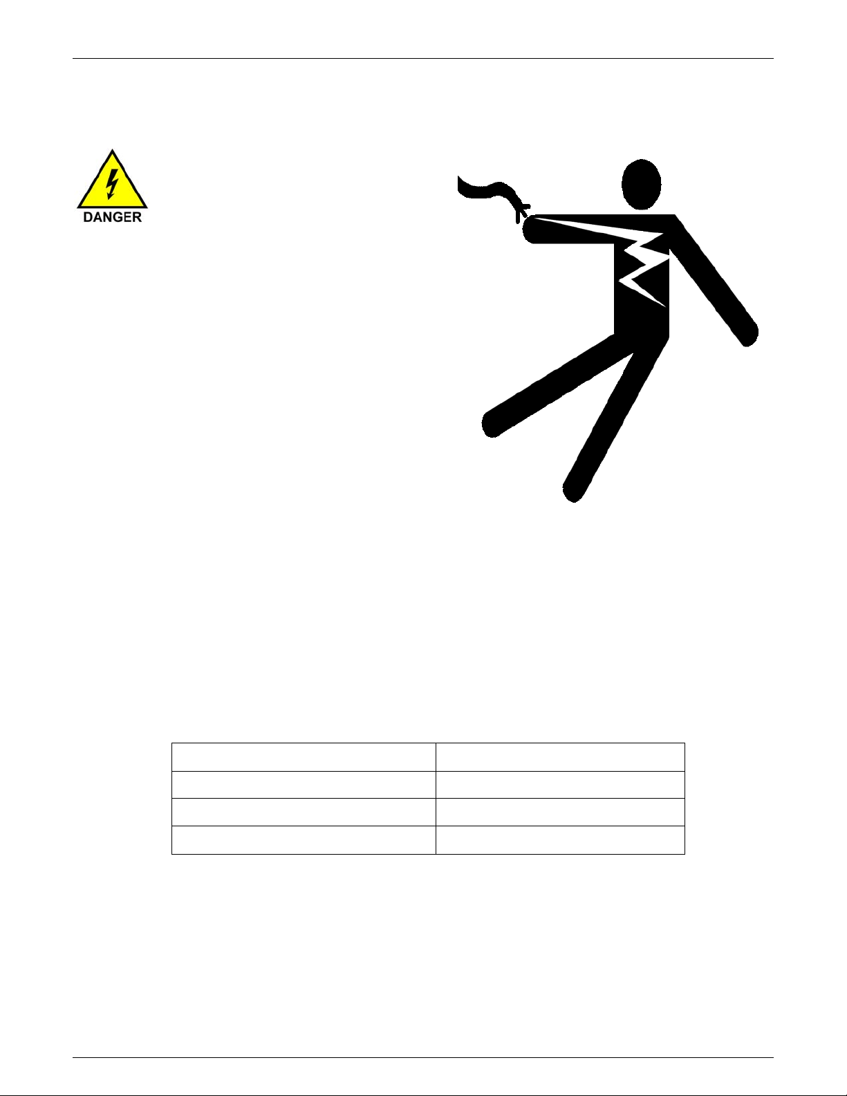
RISK OF SHOCK:
Disconnect power supply before servicing the Dryer.
GETTING STARTED: PROCEED TO: INSTALLATION - NEXT PAGE
Rev. August 31, 2016 – VBD-150
7
V
BD® - Vacuum Dryer®
Installation
Transport and Setup
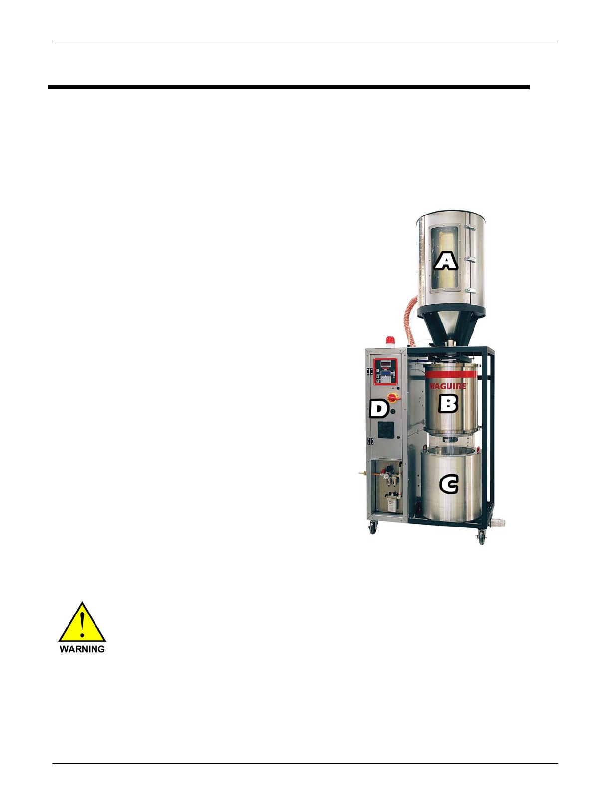
Shipment
The VBD-150 Dryer is shipped on two skids with 4 main sections.
(A) Heating Hopper Assembly
(B) Vacuum Chamber Assembly
(C) Retention Hopper Assembly
(D) Control Panel
Maguire Products, Inc.
Lifting and Moving components of the Dryer
Ensure your lifting equipment is rated to lifting the weight
of the individual sections of the VBD-150.
8
Rev. August 31, 2016 – VBD-150

V
BD® - Vacuum Dryer®
Overall layout and Dimensions
Maguire Products, Inc.
Rev. August 31, 2016 – VBD-150
9
V
BD® - Vacuum Dryer®
Maguire Products, Inc.
VBD-150 Assembly
Shipment Inventory
The VBD-150 is shipped on two pallets. One pallet holds the main body of the
VBD-150 and two cardboard boxes containing the Vacuum Chamber, the
Retention Hopper, and hardware for assembly. The second pallet holds the
heating Hopper.
Hardware includes: 1 - 2" Hose Clamp, Two RTD Assemblies (RTD Sensor, wire, plug), 4 - ½"
x13x1¼" Button Head bolts, 4 - ½" Lock Nuts, 8 - ½" Star Washers.
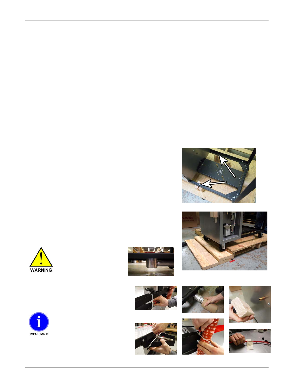
Unpacking the VBD-150 Main Body
Remove the two boxes containing the Vacuum Chamber and Retention Hopper from the pallet.
With the VBD-150 pallet on the floor, secure the wheels so
that it will not roll once it is unbolted from the pallet. Two
wheels can be locked. With the wheels secured, locate
the two shipping bolts that attach the VBD-150 to the
pallet. Unbolt the upper visible nuts from the frame and
allow the bolt to drop out of the VBD-150 frame. Remove
the Wood blocks. The VBD-150 is now detached from the
shipping pallet. Use caution.
Do not wheel the VBD-150 directly off of the pallet.
Damage to the VTA can occur. The VBD-150 can be
gently wheeled off of the pallet using stacked 2x4 pieces of
wood. Use two or more people to guide the Dryer off of
the pallet. Make sure enough clearance is given to the
VTA.
Under the Dryer there is a
VTA. Use enough ramp
clearance to prevent contact
with the VTA below Dryer.
Remove all packing material from Dryer
main body.
10
When cutting the zip-tie
located at the top rear of
the dryer, hold the
Vacuum tray and lower it
slowly onto load cell. →
Rev. August 31, 2016 – VBD-150
V
BD® - Vacuum Dryer®
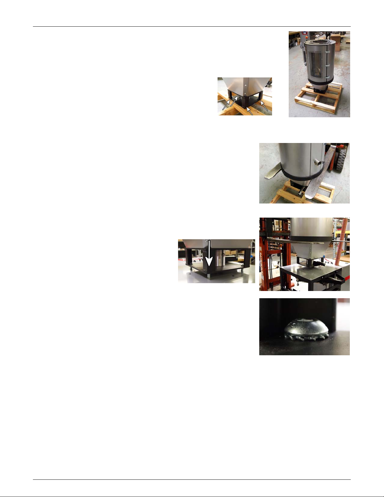
Heating Hopper Installation
The Heating Hopper is shipped on a separate pallet. The weight of the
Heating Hopper is 115 lbs (52 kg).
It is secured to the pallet with four bolts.
While holding the heating hopper securely remove
these four bolts.
Attaching the Heating Hopper
A forklift can be used to raise the heating hopper onto the VBD150 main body. Lifting points are located below on the lower
black steel ring as shown in photo on right.
Maguire Products, Inc.
Install the Heating Hopper so that the
Heating Hopper Access Door is facing
the front of the Dryer, the same side as
the Control Panel.
To assist with lining up the bolt holes, the
four ½" socket head bolts (13x1¼) can
be installed prior to lowering the Heating
Hopper onto the VBD-150.
Install the four ½" socket head bolts as follows:
Socket head bolt will receive a ½ star washer below the head.
Rev. August 31, 2016 – VBD-150
11
V
BD® - Vacuum Dryer®
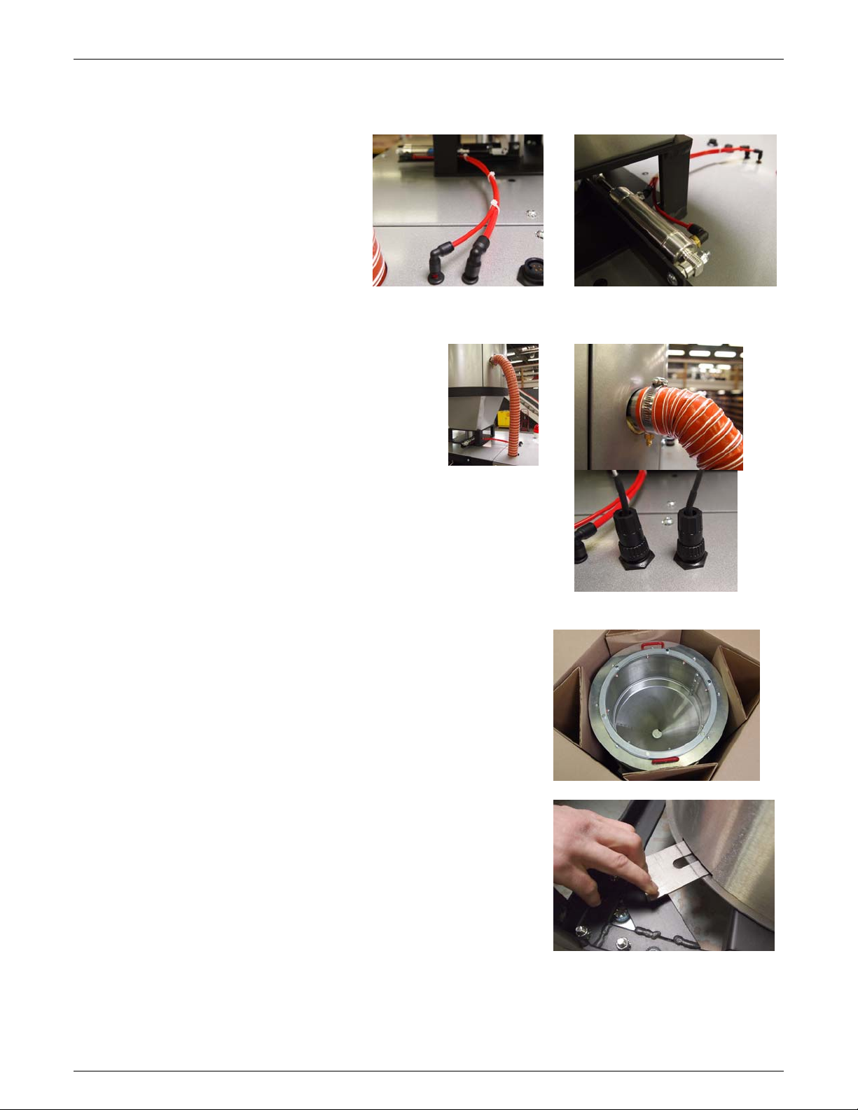
Install Connections
Attach the Heating Hopper
butterfly valve air lines.
The two air lines that connect the
Heating Hopper Air cylinder to the
VBD-150 are different sizes to
prevent an incorrect connection.
Attach the Heating Hopper Hose
Using the 2" Hose Clamp, attached the red Heating Hose
to the Heating Hopper.
Maguire Products, Inc.
Attach the RTD Plugs
The RTD plugs are different sizes and will only install on the
correct outlet.
Installing the Retention Hopper
Unbox the Retention Hopper. The Retention Hopper is
identified by the red handles located on the top of the hopper
(the Vacuum Chamber has red handles on the upper sides).
Close the slide-gate to allow the Retention Hopper to seat
down onto the base of the VBD-150. Once seated open the
slide-gate to allow material to flow.
Install the Retention Hopper so that the Retention Hopper
manual slide-gate is located at the forward right corner of the
Dryer.
12
Rev. August 31, 2016 – VBD-150
V
BD® - Vacuum Dryer®
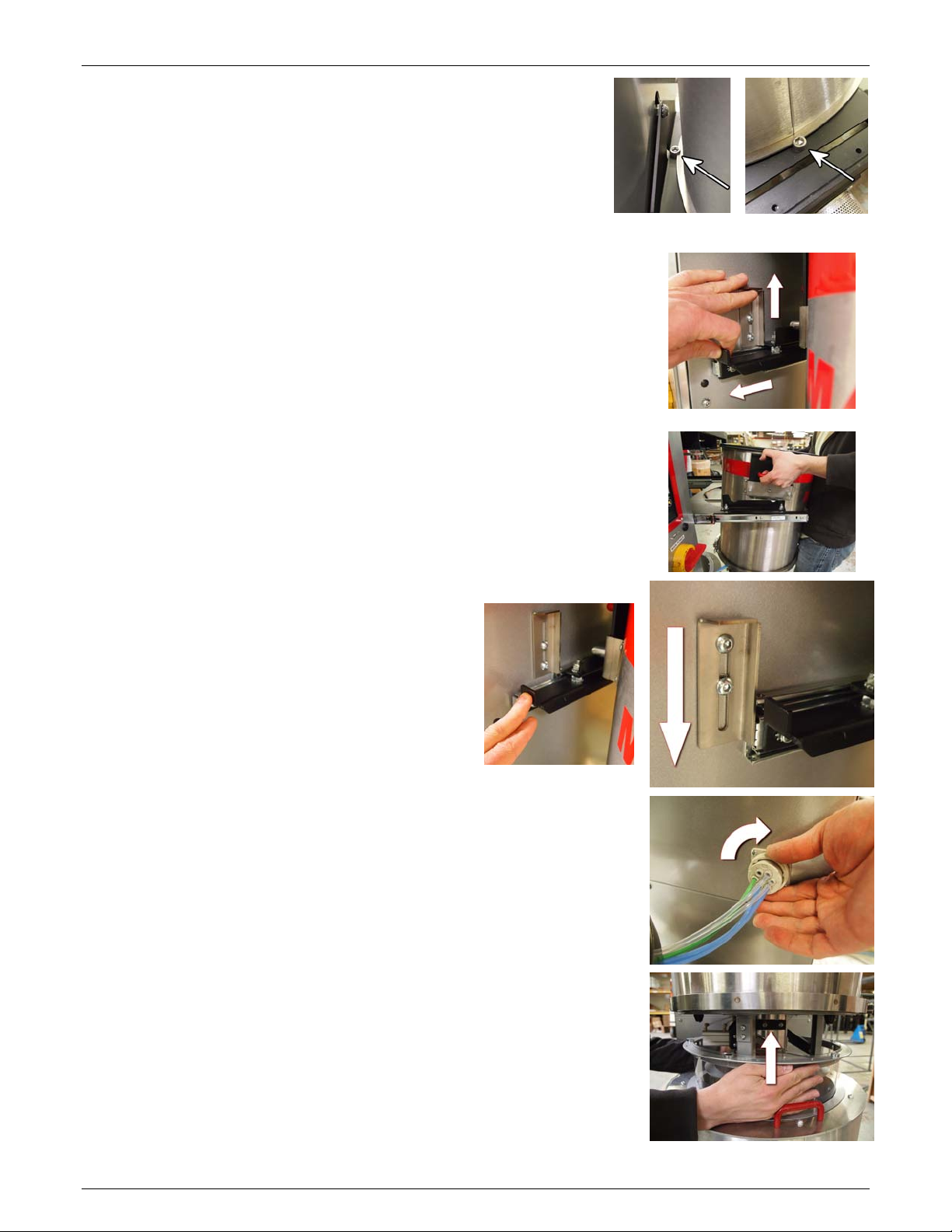
At the base of the Retention Hopper are two slots that must
be aligned with the locator bolts.
Once the locator bolts are aligned, close the press in the
slide-gate to lock the Retention Hopper in place and open the
base for material flow.
Installing the Vacuum Chamber
Unbox the Vacuum Chamber.
Lift the Slider Lock located on the right side of the VBD-150
cabinet. While holding the Slider Lock up, pull the Vacuum
Chamber slider out. Release the Slider Lock, which will rest on
top of the opened slider.
Rest the Vacuum Chamber onto the fully extended Sliders. The
Vacuum Chamber has three resting pins. Orient the side with two
resting pins on the left Slider rail.
Maguire Products, Inc.
Push the Slider rails and Vacuum Chamber
back into the Dryer until the Slider Lock falls
into place.
Connect the air lines. Rotate the locking ring fully clockwise to
secure the air connection.
Slide the Retention Hopper sealing collar up so that the magnets
engage onto the bottom of the Vacuum Chamber.
Rev. August 31, 2016 – VBD-150
13
V
BD® - Vacuum Dryer®
Maguire Products, Inc.
Dryer External Connections
Once assembled, installation requires connection of: pneumatic air line, electrical, intake and
output material lines.
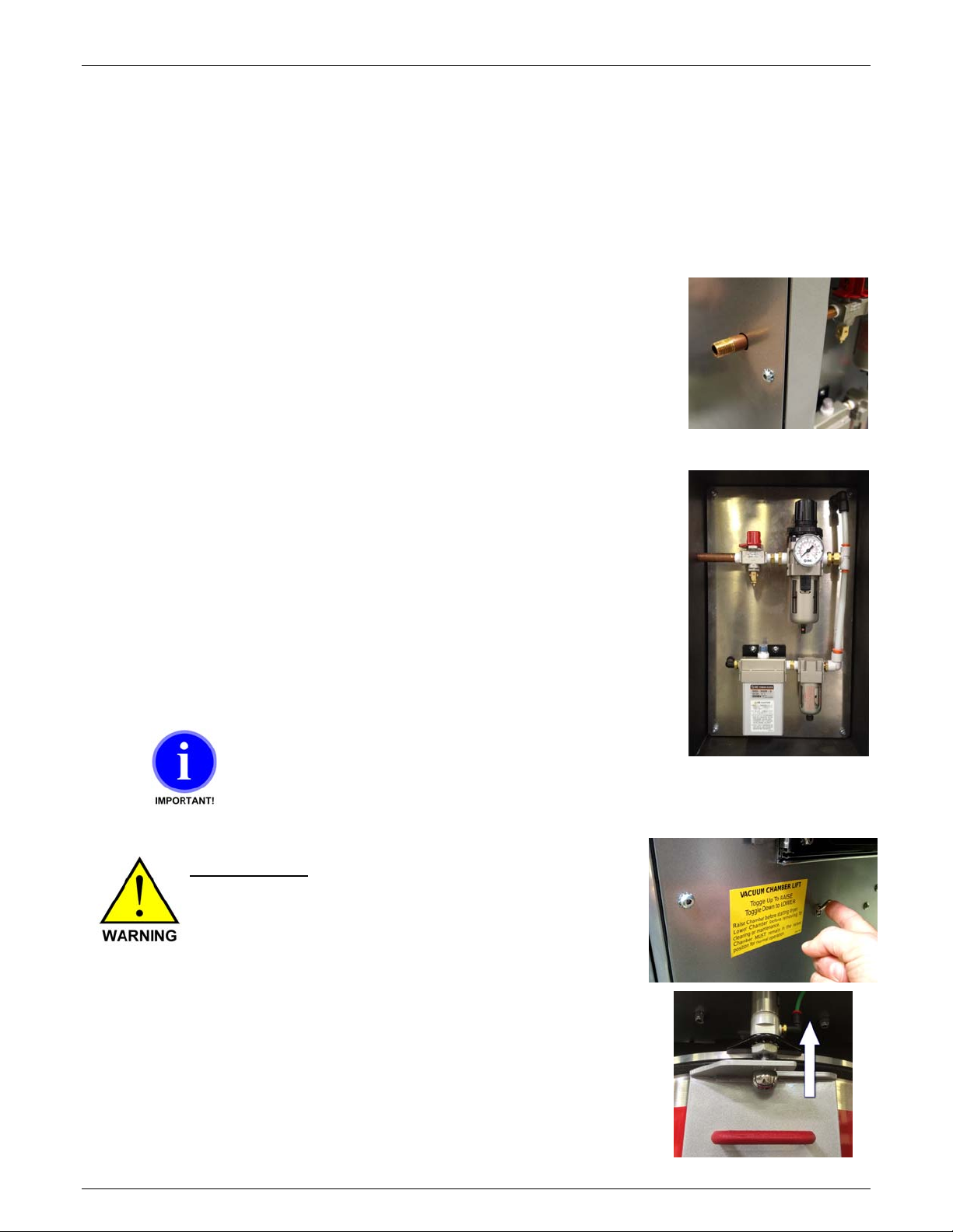
Compressed Air Connection
Connect an air supply to the air regulator’s IN port using a female
1/4” NPT pipe fitting.
An operating air pressure of 80 psi (5.5 bar) while the
vacuum generator is running is required for proper operation
of the Dryer. Setting the air pressure to 85 psi while the
machine is idle will usually attain the desired 80 psi while the
vacuum generator is running.
If your air supply has oil in it, add an oil separator (coalescing
filter). Oil in the air will combine with dust drawn from the
Vacuum Chamber forming a paste inside the vacuum generator.
It will stop working and require cleaning.
Observe the air pressure gauge to be sure the pressure
maintains 80 psi (5.5 bar) while the vacuum generator is running
as you check and adjust the regulator. If pressure drops below
80 psi, adjust the regulator. If the pressure cannot be maintained
at 80 psi (5.5 bar) while the vacuum generator is running, then
the air supply line is not adequate.
Do not supply Dryer with a lubricated air supply.
Damage to Dryer may result. Use only a clean,
dry, oil-free air supply.
Pinch Hazard - Keep fingers clear of seal
deck, the mating surface above the Vacuum
Chamber seal.
When air pressure is turned on and the
Vacuum Chamber Lift Switch is flipped up, air
cylinders lift the Vacuum Chamber off of the
slider rails and up to the seal deck closing the
gap between the top of the Vacuum Chamber
and the seal deck.
KEEP FINGERS CLEAR
14
Rev. August 31, 2016 – VBD-150
V
BD® - Vacuum Dryer®
Electrical Connection
RISK OF INJURY!
Only qualified
technicians should
make electrical
connections.
Maguire Products, Inc.
Connect Main Power
The electrical cable
located on the left side of
the Dryer on the power
box supplies the power to
the Dryer. Within the
cable is four wires. Three
of the wires are black and labeled with a number: 1, 2, and 3.
The fourth wire is a green/yellow wire and is the ground wire.
Connect power to a properly fused disconnect.
VBD-150 Fuse / Circuit Breaker Rating Table
Protect the unit with fuses or circuit breakers at the amp ratings shown below:
voltage amps
240 25
400 15
480 15
575 15
See page 73 for the High Voltage Wiring Diagram
Rev. August 31, 2016 – VBD-150
15
V
BD® - Vacuum Dryer®
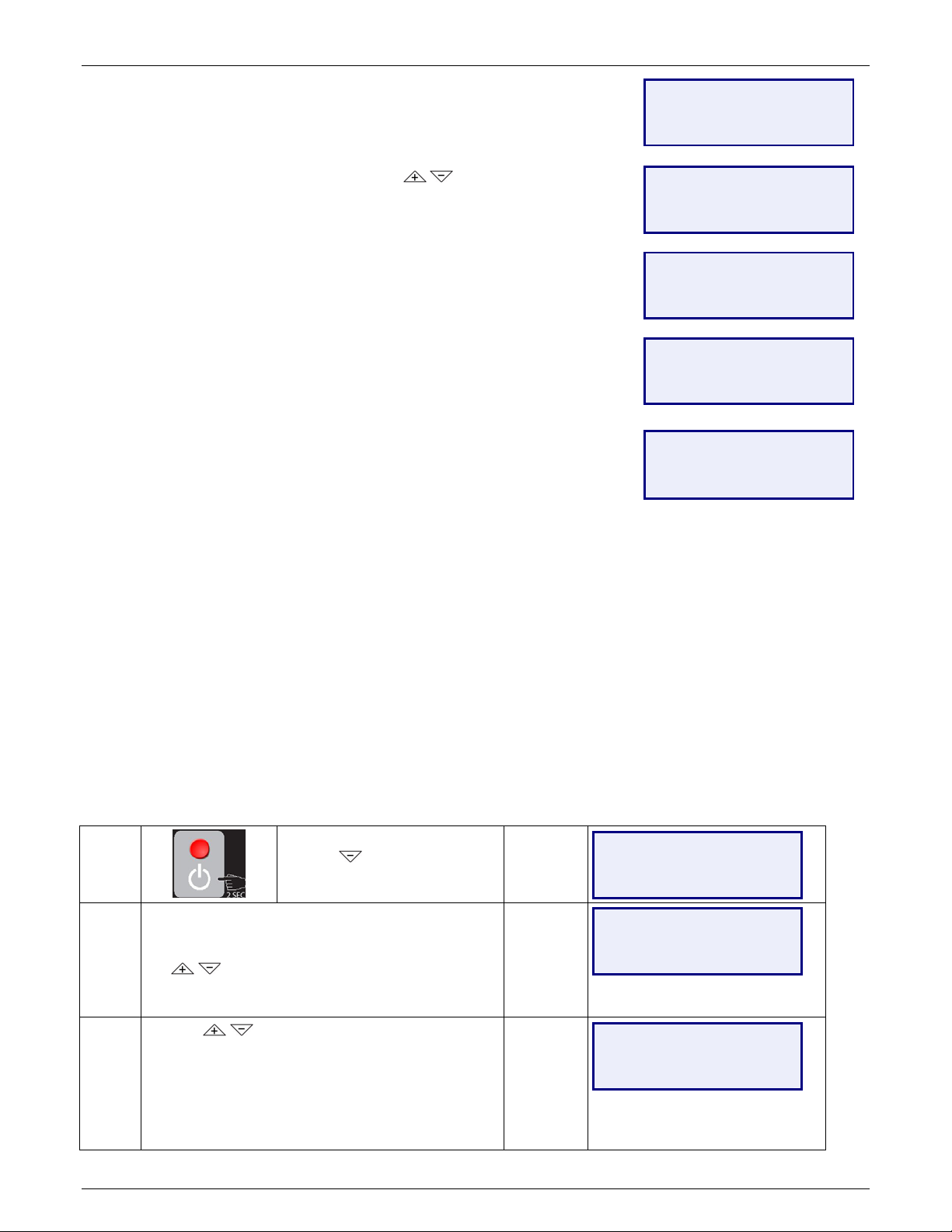
Confirm Correct 3-Phase Electrical Connection
THREE PHASE Unit - CONFIRM proper 3-Phase power connection prior to
loading material. Failure to confirm proper 3-phase connection can result in
reversed blower rotation and damage to blower if the blower sucks in material
from heating hopper rather than blow heated air into heating hopper.
To confirm proper 3-phase connection following these instructions:
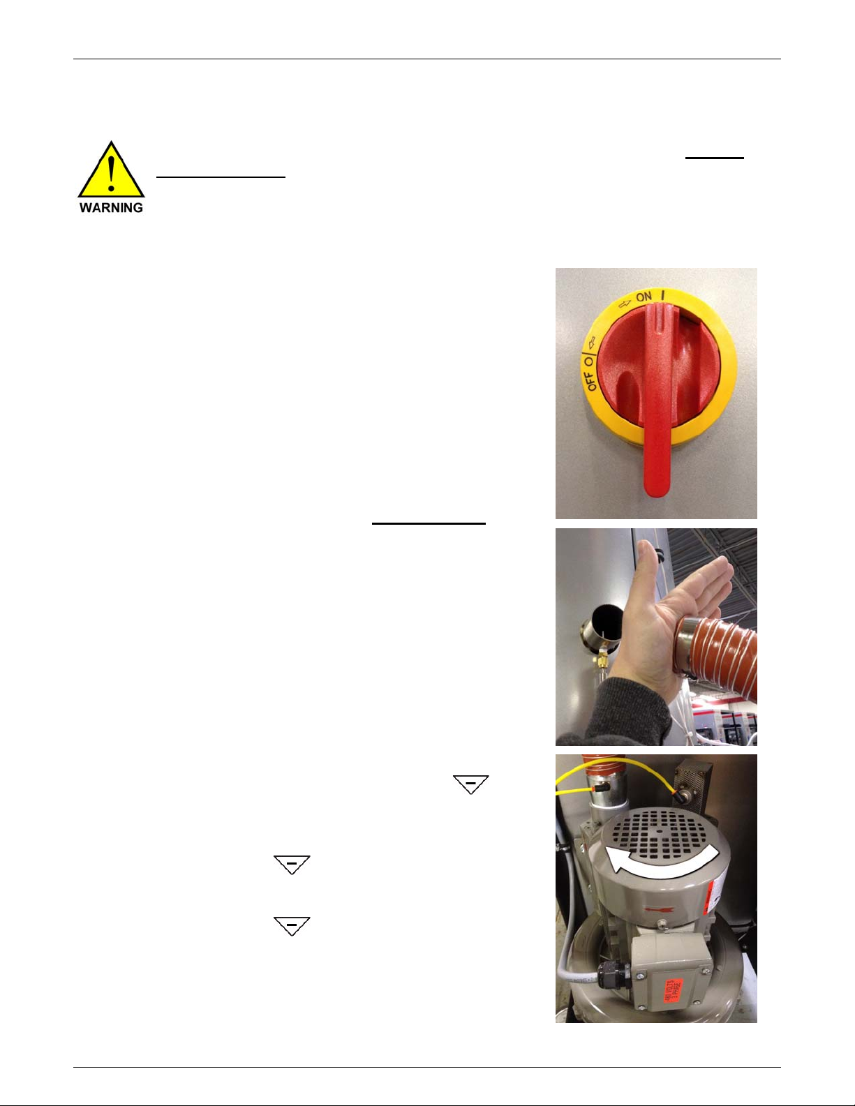
Turn power on using main power switch.
There are two methods to confirm proper
3-phase connection:
Incorrect 3-phase connection will result in
reversed blower rotation. Both methods
for checking correct 3-phase connection
involve testing the blower rotation.
Method one requires the disconnecting the
2-inch hot air hose from the heating hopper
and manually turning on the blower. The
air from the blower should blow out of the
2-inch hose. Air should not suck into the
hose. If air does not blow out and sucks in,
the 3-phase connection is NOT correct.
Method two requires the removal of the left
side panel to view the blower and confirm
blower rotation on power up. Rotation
must be clockwise as indicated by the red
arrow.
1. From the Main Screen press
to highlight Manual Operations.
Press ENTER.
2. Press to select Operate
Outputs. Press ENTER.
3. Press
to select Blower. Press
ENTER to start blower. Press
ENTER again to stop blower.
Maguire Products, Inc.
16
Rev. August 31, 2016 – VBD-150
V
BD® - Vacuum Dryer®
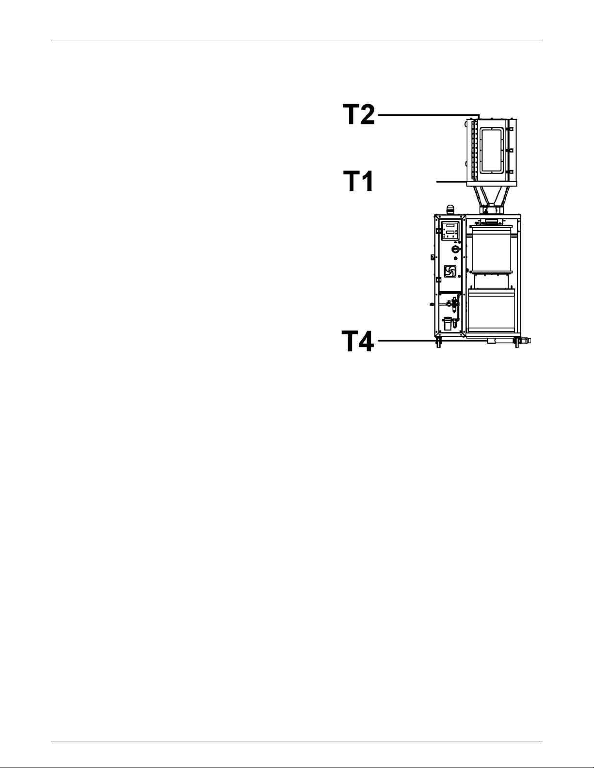
Dryer Overview
T1 – Heating Hopper Inlet Temperature
T1s – Heating Hopper Air Inlet Temperature Setting
T1a – Heating Hopper Air Inlet Temperature Actual
T2 – Heating Hopper Outlet Temperature
T4 – Material Outlet Temperature (optional)
Maguire Products, Inc.
(T1s,T1a)
Rev. August 31, 2016 – VBD-150
17
V
BD® - Vacuum Dryer®
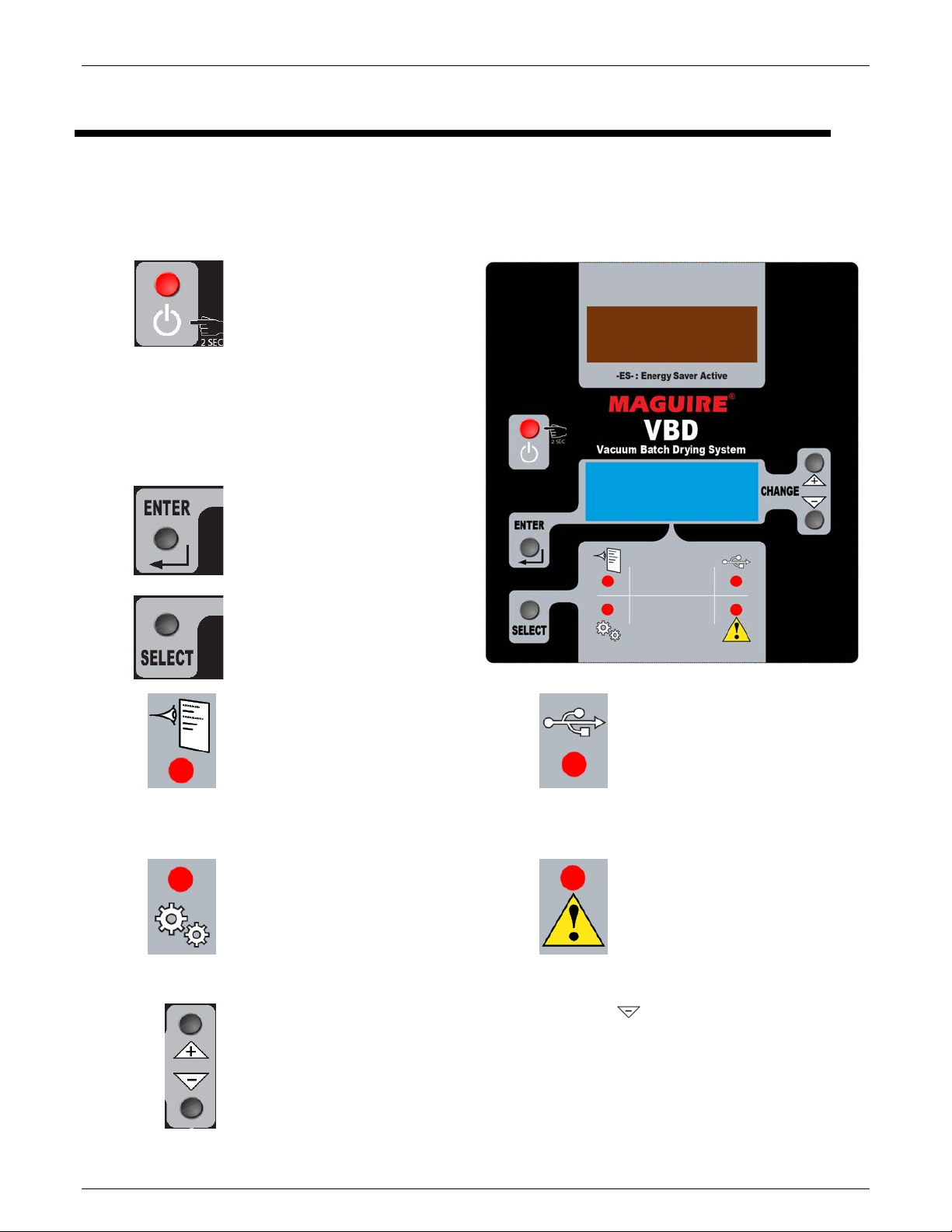
Operating Station Overview
Control Panel Overview
Display Screens – The VBD control panel has two screens. The upper, red display shows Actual
Temperature or Throughput. The lower, blue display shows various running mode information or setup
and configuration information.
Control Panel Power Powers on
the control panel (main power
must be ON.) Also used to exit or
cancel out of any menu option
and return to the top level screen.
Top Level Menu:
• Run Dryer - See page 19
• Run Dryer (Batch) – See page 41
• Clean Out – See page 49
• Manual Operations - See page 25
Enter selects the highlighted
menu option.
Maguire Products, Inc.
Select toggles between 4
different screen sets:
Status Screen
The Status Screen
T1a - Actual Air Temperature into the heating
hopper
T1s - Air Temperature Set-point
VTa – Vacuum Time Actual
VTs – Vacuum Time Set-point
ADV - Access to Advance Mode (page 23)
Setup Mode
Access to advanced set up information.
See Page 27
Displays:
Print Center
For printing reports, logs, and
parameters to a USB flash drive.
See page 60.
Alarm Log
Displays a buffer of 50 of the
most recent alarm logs. Note: A
printed alarm log will print the
history of alarms since the last
clear of alarm logs.
Arrow Buttons – Navigate menus, make adjustments. is also used to silence the
alarm.
Navigating to BACK and pressing ENTER exits the current menu and back one level.
18
Rev. August 31, 2016 – VBD-150

V
BD® - Vacuum Dryer®
Maguire Products, Inc.
Startup and Operation
This section will help you understand what the dryer is doing during operation from a cold start.
There are 3 concurrent operations. Heating, Vacuum and, Retention. Cold startup begins with
Preheat. Preheat only occurs before the first cycle of the dryer’s initial startup, otherwise each
cycle begins with material heating. The vacuum operation pulls and holds a vacuum on the
material for at least the Vacuum Time Set-point (or longer if material remains in the Retention
Hopper). The Retention operation holds the dried material in the Retention Hopper, blanketing
the material with hot, dry air, until the material is conveyed away.
Important: Inspect the VBD, verify that machine is clear of all material from heating hopper,
Vacuum Chamber and Retention Hopper. To facilitate a Clean Out, use the Clean Out
function accessible from the home screen.
Startup and Operation Instructions
1. ENSURE HATCH IS CLOSED. There is a hatch located on the upper
Heating Hopper. Ensure all 3 latches are closed. Also be sure the
removable Lower Retention Hopper is in place.
2. Load material into the Upper Heating Hopper. Wait for the Heating
Hopper to fill with material before starting the Dryer.
3. Turn on Main Power by rotating the 25 AMP Main Disconnect Handle
to the Red ON position. This powers up the VBD-150 Dryer.
On initial power up of the VBD, the Control Panel powers ON
automatically. If the main power is ON but the Control Panel is OFF,
press and hold the Red Power Button located on the Control Panel for
2 seconds. (Note: The VBD’s Control Panel can be powered OFF
without powering down the Main Power by pressing and holding the
Red Power button for 4 seconds).
4. After material has been loaded into the Heating Hopper,
select Run Dryer and press the ENTER button.
=== SELECT MODE ====
►Run Dryer
Clean Out
Manual Operations
Rev. August 31, 2016 – VBD-150
19

V
BD® - Vacuum Dryer®
5. The display will show the Pre-Start screen. On this screen is:
Setpoint Temp – This is heat hopper inlet temperature. By the end of
the preheat cycle time, all material in the Heating Hopper will be
heated to this temperature. By default, the Setpoint temperature is set
to 150 °F. See Recommended Heat Temperatures on page 19 for
general temperature recommendations or contact the material
manufacturer.
Preheat Time – This is the duration of heating from a cold start.
Vacuum Time – This is the minimum duration of a vacuum cycle.
Actual vacuum cycle times will vary according to the throughput. The
default vacuum time is 20 minutes. In the vast majority of drying
operations, this time is adequate and does not need to be adjusted.
Special circumstances may require different vacuum times. Please
consult a Maguire Dryer Technical for additional information.
By default, START is selected (location of cursor). If the settings you
desire have been entered previously, simply pressing ENTER once
more will start the machine. Otherwise use the arrow buttons
to navigate to the desired settings for adjustment, then press ENTER.
The display will highlight the adjustable digit.
Use the arrow buttons
advance through the digits and to complete the setting adjustment.
6. When the display is no longer in the Edit Mode (highlighted setting),
press
to toggle the selection to START. With START selected,
press the ENTER button to start the dryer.
to adjust the setting. Press ENTER to
Maguire Products, Inc.
Setpoint Temp.: 150°F
Preheat Time: 35m
►Vacuum Time: 20m
================ START
Setpoint Temp.: 150°F
Preheat Time: 35m
Vacuum Time: 18m
================►START
7. The display will show that the dryer is running in PREHEAT
mode and display the following:
T1a - Actual heating hopper inlet temperature
T1s - Heating Hopper inlet temperature setpoint.
VTa - Elapsed vacuum time.
VTs - Vacuum Time sepoint.
VAC - Actual vacuum chamber pressure.
======= PREHEAT: 35:00
T1a:130°F VTa: 00:00
►T1s:150°F VTs: 18:00
ADV ==== VAC: 760mm
==== AUTO CYCLE ====
T1a:130°F VTa: 00:00
►T1s:150°F VTs: 18:00
ADV ==== VAC: 760mm
20
Rev. August 31, 2016 – VBD-150

V
BD® - Vacuum Dryer®
Maguire Products, Inc.
What is happening when the dryer is running:
During the Pre-heat operation material in the heating hopper is brought up to temperature (T1s). Preheat
time is determined by the specified Preheat Time on the Pre-Start screen (timed preheat, default 35 minutes)
or by the Preheat Setup Auto option, which sets an inlet to outlet temperature delta and a minimum preheat
time.
After pre-heat, approximately one third of the material in the heating hopper is dispensed into vacuum
chamber, and the first vacuum cycle begins. Each vacuum cycle has a minimum vacuum time, set on the
Pre-start screen, or the main run screen (VTs). (default is 20 minutes).
The loader loads the Heating Hopper with new material as the Vacuum Chamber receives the heated material
and heating cycle begins concurrent to vacuum cycle (the first vacuum cycle is timed). The new batch of
material in the upper portion of the heating hopper will take less time to heat. Minimum time in the heating is
dictated vacuum time.
After first vacuum cycle, material is then dispensed into retention hopper ready for use. Material in the
retention hopper is blanketed with dry air.
The rate of consumption of dried material from the retention hopper ultimately dictates the amount of time that
the material will be preheated and under vacuum. Examples: If it takes 25 minutes to deplete the retention
hopper, the vacuum cycle will run past its 20 minute setpoint (pre-start screen) to 25 minutes. This is normal
operation. However if the retention hopper is depleted in 15 minutes and the vacuum time is set to 20
minutes, there will be a 5 minute window where no material is available. This indicates that the throughput of
the dryer has been exceeded. If the Throughput Alarm is enabled (Alarm Setup), a Throughput Alarm (Alarm
Code 20) will be triggered.
Rev. August 31, 2016 – VBD-150
21
V
BD® - Vacuum Dryer®
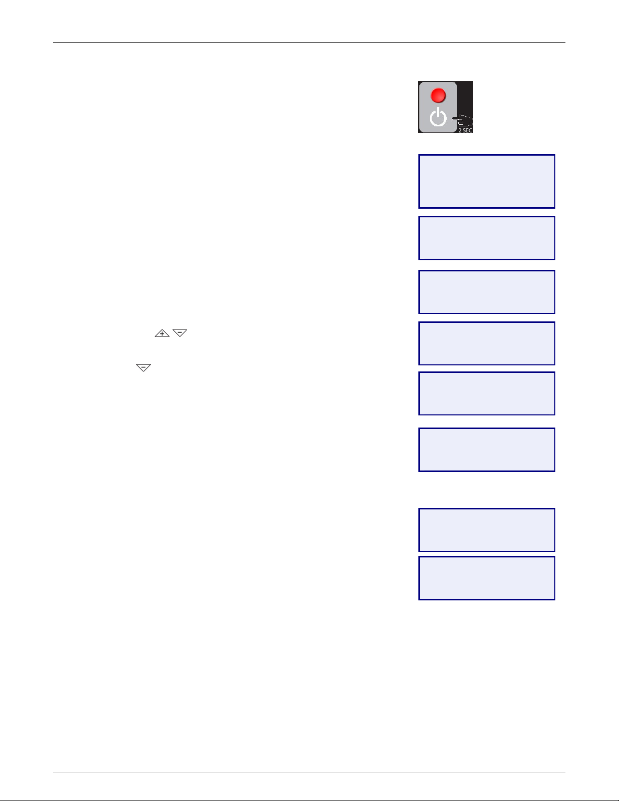
Shutdown, Auto Shutdown, Immediate Shutdown
At any point during the preheat cycle or standard operation
(operation after initial preheat cycle), pressing the red button will
bring up a Shutdown Options screen and display.
Shutdown - Shutdown during post-preheat operation
Pressing the red power button once during post-preheat operation
prompts the operator with these options:
Shutdown – Shutdown will run to run the dryer and process the material
in the Vacuum Chamber and the Retention Hopper until they are empty.
Selecting Planned Shutdown will display the Cooldown option.
Cooldown (ON/OFF) – When enabled Cooldown will gradually bring
down the temperature of the material in the heating hopper to the
specified temperature (Cooldown Temp) over the specified time period
(Cooldown Time).
To adjust the Cooldown Temperature and Cooldown Time use the
arrow buttons
through the digits and to complete the setting adjustment.
Press the
shutdown. Press the ENTER button to proceed with the shutdown.
Pressing the red power button during a Planned Shutdown will display
the Immediate Shutdown Screen allowing initiation of an immediate
shutdown of the dryer.
Auto Shutdown – Initiates a shutdown (see above) as specified date and
time. For further explanation on how to set the Auto Shutdown Date and
Time see page 23.
Immediate Shutdown – Fast but controlled shutdown of the heater,
blower, the vacuum system and the purge system.
Cancel - Exits the shutdown prompt screen, doing nothing.
Skip Preheat (shown only if in a preheat cycle) – Skips the preheat
allowing material to immediately pass down to the Vacuum Chamber
(example: material has already been heated and dryer has been taking
offline briefly and powered back on).
to adjust the setting. Press ENTER to advance
to scroll down to Shutdown to continue with the
Maguire Products, Inc.
====== SHUTDOWN ======
►Shutdown
Auto Shutdown
Immediate Shutdown
Cancel
===== SHUTDOWN ======
Cooldown:OFF
Cancel
►Shutdown
===== SHUTDOWN ======
Cooldown:ON
Cooldown Temp:120°F
►Cooldown Time: 60m▼
===== SHUTDOWN ======
Cooldown:ON
Cooldown Temp:120°F
►Cooldown Time: 30m▼
===== SHUTDOWN ======
Cooldown Temp:120°F
Cooldown Time: 30m
►Cancel ▼
== PLANNED SHUTDOWN ==
Cooldown Time: 30m
Cancel
►Shutdown
== COOLDOWN: 29:58
T1a: 120°F VTa: 14:37
►T1s: 120°F VTs: 20:00
ADV ==== VAC: 82mm
H:OFF B:ON Pabs:752
Shutting Down…
-=- Standby -=-
22
Rev. August 31, 2016 – VBD-150
V
BD® - Vacuum Dryer®
Maguire Products, Inc.
ADVANCED (ADV) - Selecting ADV (advanced) will display additional
information such as readings of all RTD thermometers, vacuum time elapsed,
absolute pressure in the Vacuum Chamber, blower drive frequency. ADV also
allows an option to abort preheat and proceed into vacuum cycle. (Aborting the
preheat cycle does not shut down the machine). Advanced scrolls through 4
screens. To move to the next screen, use the
buttons to navigate.
Fill Weight – The desired weight of material to be dispensed into the Vacuum
Chamber.
Bulk Density - Bulk density of the material in either pounds per cubic foot or
kilograms per liter (depending on the weigh unit of measurement in Loadcell
Setup).
Vac Cham. - Current material weight in Vacuum Chamber.
Ret. Hopp. - Current material weight in Retention Hopper.
Thruput - Calculated throughput, weight per hour.
Totalizer - Calculated total of all cycles since last clear of totals.
Last Cycle * - Total time to process a completed batch of dry material.
Cycle Count * - Total number of cycles since start button was pressed.
Fill Time * - Total time to fill the Vacuum Chamber.
T1 - Show actual temperature of the heating hopper inlet. & heating %.
T2 - Show Actual temperature of the heating hopper outlet.
T4 - Show Actual temperature of the retaining hopper.
==== AUTO CYCLE ====
T1a:149°F VTa: 07:57
T1s:150°F VTs: 20:00
►ADV ==== VAC: 78mm
I/O:BHVC ►BACK
Fill Weight: 35LB
Vac. Cham.:+ 35LB
Ret. Hopp.: 27LB▼
I/O:BHVC ►BACK
Thruput: 75LB/HR▲
Totalizer: 778LB
Last Cycle: 21:06▼
I/O:BHVC ►BACK
Cycle Count: 5▲
Fill Time: 18.697
T1:149/150°F H:19% ▼
I/O:BHVC ►BACK
T1:149/150°F H:19% ▲
T2:106°F T4: 145°F
* These advanced menu options can be turned on / off in the DISPLAY SETUP menu.
Auto Shutdown
At any point during the preheat cycle or standard operation (operation after initial preheat cycle),
pressing the red button will bring up a Shutdown Options screen and display.
Press:
to display the shutdown screen.
Use the
button to navigate
down to Auto Shutdown.
Press: The display will show the current date and time
above the Auto-Shutdown date and time. You are
adjusting the Auto-Shutdown date and time. Use
the
buttons to navigate down to the lower
Display
will show:
Display
will show:
====== SHUTDOWN ======
Shutdown
►Auto Shutdown
Immediate Shutdown
AUTO-SHUTDOWN BACK
Mon 10/30/2014 12:30
Mon 10/30/2014 00:00
► Month: 1-12
adjustment field to adjust the date and time for the
Auto-Shutdown to occur.
Press: Use the buttons to adjust the digit and
press ENTER to save that edited field and move to
the next field. When complete (NEXT will display
to indicate you have completed edit of all fields),
Display
will show:
AUTO-SHUTDOWN BACK
Mon 10/30/2014 12:30
Mon 10/30/2014 16:30
►NEXT ================
press ENTER to finish. The Home Screen will now
display "AUTO-SHUTDOWN" at the top to indicate
the dryer is in an Auto-Shutdown mode.
Rev. August 31, 2016 – VBD-150
23
V
BD® - Vacuum Dryer®
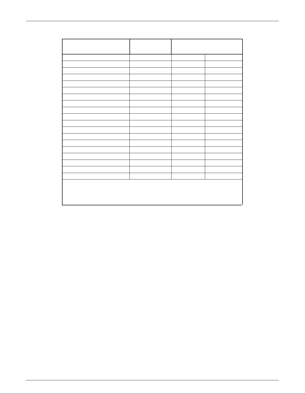
Recommended Drying Temperatures
MATERIAL
FINAL
MOISTURE % *
Maguire Products, Inc.
DRYING TEMPERATURE**
ºC ºF
ABS
ABS/PC
LCP
PA
PBT
PC
PC/PBT
PEEK
PEI
PES
PET (Molding Grade)
PET (Preform, Extrusion)
PMMA (Acrylic)
POM (Acetal)
PPO
PPS
PUR
PSU
SAN
* Final moisture content as recommended by the raw material manufacturer.
** Drying temperature as recommended by the material manufacturer.
0.10 80 - 85 180 – 190
0.02 100 210
0.02 150 300
0.20 - 0.10 80 - 85 180 – 190
0.02 120 250
0.02 125 250
0.02 125 250
0.20 - 0.10 150 300
0.02 150 300
0.05 - 0.02 150 300
0.010 150-180 300-350
0.005 150-180 300-350
0.02 - 0.04 79 175
0.20 - 0.10 80 - 110 180 – 230
0.02 100 - 120 210 – 250
0.02 150 300
0.02 125 - 140 260 – 280
0.02 150 300
0.20 - 0.10 80 180
Drying is accomplished when all material reaches the proper
temperature, and is then placed under sufficient vacuum for a sufficient
period of time.
Measurement of moisture content of material, both prior to and after
drying, is accomplished by using a moisture analyzer.
24
Rev. August 31, 2016 – VBD-150

V
BD® - Vacuum Dryer®
Maguire Products, Inc.
Description of Menu Options
Select Mode (Top Level Menu)
Three modes of operation: Run Dryer, Clean Out and Manual Operations.
Run Dryer - See Operation on page 19.
Clean Out – Clean Out opens all valves and allows for material evacuation and cleanout.
Dump Heat Hopper – Opens the Vacuum Chamber Fill Valve, drains the Heating
Hopper.
Dump Vacuum Chamber – Opens Vacuum Chamber dump valve, draining Vacuum
Chamber
Dump All – Opens both the Vacuum Chamber Fill Valve and Vacuum Chamber dump
valve
Manual Operations – Options that allow direct control over specific outputs.
Operate Outputs
Alarm Audio – OFF/ON – Operates audible alarm.
Alarm Strobe – OFF/ON – Operates strobe.
Dry Purge Supply – CLOSED/OPEN of dry purge supply air valve
Vac Gate Upper – OPEN/CLOSED – Material gate above vacuum chamber.
Vac Gate Lower – OPEN/CLOSED – visible disk shaped gate below vacuum
chamber.
Vac Cham Fill – OPEN/CLOSED - Gate located at the base of the heating
hopper.
Vac Cham Dump – OPEN/CLOSED – Internal gate (not visible) located at the
base of the vacuum chamber.
Vac Gen Supply – OPEN/CLOSED – Vacuum generator supply. When
operating, the vacuum generator supply pulls a vacuum on the vacuum chamber.
Vac Gen Check – OPEN/CLOSED – Vacuum generator check valve located on
the vacuum generator. Holds the vacuum on the vacuum chamber.
Vac Cham Purge – OPEN/CLOSED – Located below the vacuum generator.
When open the vacuum on the vacuum chamber is released.
Heater Test – Operates the heater and blower that supplies heat to the Heating
Hopper.
T1s: Heating Hopper inlet temp setpoint.
T1a: Heating Hopper inlet temp actual.
Start: Starts the heater test. Blower will run during test.
Heater Output: Heater duty cycle expressed in percent
Blower: Status of blower
Control: PID or manual. Controller will modulate the heater as it would during
auto cycle. In manual mode the operator can select a heater duty cycle.
Edit Settings: Easy access to heater control parameters
Blower Test – Operates the blower.
Blower: OFF/ON toggle using ENTER button.
Aux: OFF/ON toggle using ENTER button.
Fail Safe: OFF/ON toggle using ENTER button.
Rev. August 31, 2016 – VBD-150
25

V
BD® - Vacuum Dryer®
T1s: Heating Hopper inlet temp setpoint.
T1a: Heating Hopper inlet temp actual.
Vacuum Test - Tests the Vacuum System
Vac: Vacuum pressure readout
Start Test: Starts the vacuum test. Runs the vacuum generator system.
Evac Time: Amount of time in minutes/seconds to attain the vacuum setpoint
during the current test.
Cycle: Amount of time in minutes/seconds between vacuum generator runs
during a vacuum hold. Used to determine vacuum chamber seal integrity.
Pset: Absolute pressure that the Vacuum Chamber will be evacuated to. See
VPL parameter.
Pdel: The pressure difference above VPL at while the vacuum generator turns
back on. See VPD parameter.
Purge Cham: Enables or disables the dry purge.
Input Status – Shows status of various inputs
Blower – OFF/ON
Level – Heating Hooper Level (0-100%)
Pressure – LOW/OK
VAC – Vacuum chamber absolute pressure (mmHg)
Primary OT – Primary Heater temperature switch - OK/OVERTMP
Purge OT - Purge Heater temperature switch - OK/OVERTMP
HH Rem. Dump – Remote heating hopper dump – ON/OFF
VC LC – Raw counts of the vacuum chamber loadcell
RH LC - Raw counts of the retention hopper loadcell
T1 – Heating hopper inlet temperature
T2 – Heating hopper outlet temperature
T4 – Optional material exit temperature
Timed Dispense – .
Fill: Fill Time of the Vacuum Chamber in milliseconds.
Dump: Dump time of the Vacuum Chamber in milliseconds.
Maguire Products, Inc.
26
Rev. August 31, 2016 – VBD-150

V
BD® - Vacuum Dryer®
Maguire Products, Inc.
Setup Menu
The Setup Menu is accessed by pressing the Select button and choosing the Wrench mode.
Press:
to toggle the Mode Selection
to the Wrench Icon.
Enter: the 5-digit password. (Default password is 22222).
Use the
ENTER to move to the next digit and to finish.
Press: the button several times to move down to the desired option.
Press ENTER to select that Setup option for modification.
Setup Menu Option Description / Options
Alarm Setup
buttons to adjust the digit. Press
Material Shortage Alarm
WARN: In the event of a material shortage, activate
SHUTDOWN: In the event of a material shortage, activate
OFF: Disables the Material Shortage alarm
When Material Shortage Alarm is in Warn or Shutdown Mode
Fill Retries are ENABLED. When set to OFF, Fill Retries are
disabled.
Material Ready Alarm - If the Material Ready alarm is enabled, this
alarm will trigger after the first and only first batch of material has
completed a full vacuum cycle. After 15 seconds, the audible
portion of this alarm will automatically silence. The first batch of
material will remain under vacuum indefinitely until this alarm is
cleared. There are two main purposes of this alarm:
1. To alert the operator that dry material is ready for the process.
2. To act as a hold-back, when necessary, giving the operator
additional time to prepare the process.
ON: When the Material Ready Alarm is enabled,
OFF: Disables the Material Ready Alarm
(labeled "Material")
the audible alarm and strobe light but
continue retrying for material.
the audible alarm and strobe light and
automatically initiate a planned shutdown.
Audible alarm with sound for 15 seconds and
the strobe will flash until the dryer is
completely shut down.
the alarm will sound when this alarm is
triggered.
Display
will show:
Display
will show:
SETUP
ENTER PASSWORD
_ _ _ _ _
SETUP
► Alarm Setup
Auto-Start Setup
Blower Setup ▼
Rev. August 31, 2016 – VBD-150
27

V
BD® - Vacuum Dryer®
Maguire Products, Inc.
Material Temperature Alarm - When the Material Temp alarm is
enabled, during any instance where the Heating Hopper is called
upon to dispense material into the vacuum chamber and the T2
(heating hopper exit) temperature is below the ESM parameter
level, this alarm will trigger. Its purpose is to alert the operator that
insufficient heating has occurred, most likely from a process
throughput that exceeds the capacity of the VBD.
ON: When the Material Temperature Alarm is
enabled,.
OFF:
Residence Alarm (labeled “Residence”) -
Disables the Material Temperature Alarm
When the Residence Alarm
is enabled, an alarm will sound if dried material has sat in the
retention hopper too long. The RAL parameter determines when a
residence alarm will occur based on elapsed time and weight of
remaining material in the retention hopper. See the RAL parameter
for more information.
ON: When the Residence Alarm is enabled, the
alarm will sound when this alarm is triggered.
OFF:
Throughput Alarm (labeled "Thruput") -
Disables the Residence Alarm
If the Throughput alarm is
enabled, the alarm will sound if the material in the Retention Hopper
is used faster than the dryer can produce dried material. (Material
level reaches RTL parameter before the Vacuum Time Setting
expires VTS parameter)
ON: If the Throughput alarm is enabled, the alarm
will sound when this alarm is triggered.
OFF: Disables the Throughput alarm
VC Dump (Vacuum Chamber Dump) Alarm -
If the Vacuum Chamber
Dump alarm is enabled, the dispensing of material from the vacuum
chamber into the retention hopper is monitored using the CDR
(Chamber Dump Retries) parameter. CDR’s default settings of
05003 requires that at least 50% of the material that is in the
vacuum chamber be detected in the retention hopper after the
dispense. If it’s under 50% the dispense will retry 3 times before
triggering the alarm. Retries will continue indefinitely until 50% is
satisfied.
ON: If the Vacuum Chamber Dump alarm is
enabled, the alarm will sound when this alarm
28
Rev. August 31, 2016 – VBD-150

V
BD® - Vacuum Dryer®
Maguire Products, Inc.
is triggered.
OFF:
Disables both the vacuum chamber dump
alarm and vacuum chamber Dump retries.
Print Alarm Log - Prints the Alarm Log. See page 60.
Clear Alarm Log - Clears the Alarm Log. See page 60.
Auto-Start Setup
Auto-Starts the Dryer at a specified Time and Day(s). Can be set to
Auto-Start the Dryer at one time only or on a repeated schedule.
Auto-Stop Setup
Auto-Stop the Dryer at a specified Time and Day(s). Can be set to
Auto-Stop the Dryer at one time only or on a repeated schedule.
Communications
Communication setup. See page 42.
Convey Setup
Convey Setup - Material Convey Options - Optional - Uses
dedicated outputs on the I/O board that may be used to control
customer supplied Loader(s).
See the I/O Board Wiring Diagram on page 73
• Loader 1 - Off / Auto - Stops loader that supplies the heating
hopper for shutdown sequence.
• Loader 2 - Off / Auto - When material is ready, loader will
convey material away from dryer retention hopper. When
enabled, select Throughput or Weight.
• Reset Totalizer - Resets Weighed totals to zero. Totals are
the amount of material that has been conveyed away from
the dryer since the Totalizer has been reset.
Dispense Setup
Fill Weight – The desired weight of material to be dispensed into
the Vacuum Chamber.
Bulk Density – Bulk density of the material in either pounds per
cubic foot or kilograms per liter (depending on the weigh unit of
measurement in Loadcell Setup).
Fill Wt. Adj (Fill Weight Adjust) – Off / On – When ON the dryer
will automatically adjust the fill weight to be in appropriate proportion
with the throughput. A Low throughput will result in a lower fill
weight.
Display Setup Show / Hide Information and options on the controller screens
Batch Mode - ON/OFF – When ON, the option to dry a batch
of material is displayed on the home screen.
Auto Shutdown - ON/OFF – When ON, the option to initiate
an auto shutdown (shut down at a specified time) is
displayed on the shutdown options screen.
Rev. August 31, 2016 – VBD-150
29

V
BD® - Vacuum Dryer®
Maguire Products, Inc.
I/O Status – ON/OFF – Displays I/O info on main screen.
Cycle Info - ON/OFF – Displays Cycle info on main screen.
Fill Time - ON/OFF – Displays the fill time on main screen.
Residence Time - ON/OFF – When ON, displays a
countdown timer (RAL parameter) indicating when an alarm
will sound alerting that material has sat in the retention
hopper too long.
Display – TEMP/THRUPUT – Sets the upper red display to
show either actual temperature or throughput (lbs or kgs per
hour).
Dry Purge Setup Purge Cham -
ON/OFF
- Supplies membrane dried air to purge the
Vacuum Chamber and blanket the retention hopper. When enabled
the dryer will supplied air all the time even if dryer is in a STOP
mode.
Purge Interval - Interval in seconds between purges.
Purge Duration - Duration in seconds that the purge will occur.
Loadcell Setup
Parameters
Loadcell Setup - See page 44.
Parameters access. See page 32.
Preheat Setup Preheat Mode - Auto or time - Preheat time for the material in the
Material Hopper. Default preheat time is 30 minutes.
Preheat Time - The Preheat Time is the duration of preheat time.
Print Setup
Print Setup - See page 60
• Event Log: Enabled/disabled
• Interval: 60s (temperatures, pressure)
• Content: Standard/Detail
• Print All - Prints parameters, event log, and alarm log.
• Print Parameters - Prints the parameter list to a USB drive
• Print Event Log - Prints the event log to a USB drive
• Print Alarm Log - Prints the Alarm Log
• Clear Event Log - Deletes all entries in the Event Log
•
System
Clear Alarm Log - Deletes all entries in the Alarm Log
Display Firmware - Displays CPU, I/O board, Model, Boot loader.
Language - Select Language
30
Rev. August 31, 2016 – VBD-150

V
BD® - Vacuum Dryer®
Temperature Setup
Energy Saver
Vacuum Setup
Maguire Products, Inc.
Set Clock - Set time, date and date format.
Memory - Current memory status.
Password - Sets the Setup Menu Password. Default password is
22222. Setting the password to 00000 disables password
protection.
Restore Parameters - Restores all parameters back to factory
defaults
Restore All - Restores Factory Defaults. WARNING: Only apply
Restore All when directed by a Maguire Technician.
Update Firmware - Update VBD-150 Firmware. See page 69.
Units: Fahrenheit (F) or Celsius (C)
Display Precision: “Standard” displays temperature in whole
degrees. “High” displays temperature in 10ths of a degree.
Energy Saver (OFF/ON): On enables Energy Saver Mode. Energy
Saver Mode when enabled minimizes the amount of energy used to
heat the pellets by shutting down the heater and blower when
possible to conserve energy. When the heating hopper’s outlet
temperature has reached the temperature specified in the Energy
Saver Setup (E.S. Temp), the heater and blower will shut down for
the time period specified in Energy Saver Setup (E.S. Time) or until
the cycle ends, which ever comes first.
E.S. Temp (ESM parameter): Default 125 degrees F.
E.S. Time (EST parameter): Default 30 minutes.
Vacuum Time (Tvac): Amount time the vacuum will run.
Pressure Set Point (Pset): 085mmHg Absolute pressure that the
Vacuum Chamber will be evacuated to.
Pressure Delta (Pdelt): (020 mmHg) Vacuum Deadband
Display: ABS/DIFF Air pressure display, Absolute pressure
(referenced from zero or perfect vacuum, differential pressure
referenced from atmosphere.
Unit: Option to display mmHg (Millimeters of mercury) or inHg
(inches of mercury)
Rev. August 31, 2016 – VBD-150
31

V
BD® - Vacuum Dryer®
Maguire Products, Inc.
Parameters
All Maguire VBD controllers operate according to certain internal PARAMETERS.
Because customer requirements vary widely, we have made parameters accessible for
change through the keypad. In most cases, these parameters will never need to be
changed. Some parameters that are routinely adjusted values are adjustable from the
main display. To access and edit the parameters, see Changing Parameters in this
section:
Changing parameters can have an impact on the Dryers performance. It is highly
recommended that a supervisor change the default Program Mode password to protect the
values. Prior to making any changes, make sure you understand what you are doing. If in
doubt contact a Maguire Dryer Technician before making changes to your dryer.
Blower Parameters: Heater Parameters:
BDT Blower Delay Time PTS Preheat Temperature Setting
BLF VFD Low Limit PHT Preheat Time
BHF VFD High Limit PTD Preheat Target Delta
BDF VFD Frequency RTS Run Temperature Set-Point
BZL VFD Zero Level PT1 PD Loop Proportional
BLA VFD Level Adjustment DT1 PD Loop Derivative
BHT VFD Heat Throttle UT1 PD Loop Update Time
Dispensing Parameters:
VCH Vac. Chamber Hi Level NH1 Heat1 No Heat Alarm
VCL Vacuum Chamber Low Level SO1 Heat1 Set-Point Off. Percent
RHH Ret. Hopper Hi Level MP1 Heat1 Max Percent
RHL Retention Hopper Low Level MAX Max Temp Set-Point
BLK Bulk Density ESM Energy Savings Mode
VFR Vacuum Chamber Fill Rate EST Energy Savings Time
VDR Vacuum Chamber Dump Rate RMP Temperature Ramp Settings
VFT Chamber Fill Time CTM Cool-Down Temperature
VDT Chamber Dump Time CTR Cool-Down Timer
FLA Fill Lag Time
DLA Dump Lag Time KDF Loadcell Stable Wt.
VGD Vacuum Gate Delay LST Load Cell Stable Time
VFA Chamber Fill Adjust LCZ Loadcell Zero
HDD Heating Hopper Dump Delay WST Weight Settle Time
VCT Vacuum Chamber Dump Threshold LZ1 Loadcell 1 Zero
CDR Chamber Dump Reties LZ2 Loadcell 2 Zero
RAL Residence Alarm
BCH Batch Size VTS Vacuum Time Setting
LTP Loader Trip Point VPL Vacuum Pressure Low
LTC Loader Thruput Cutoff VPD Vacuum Pressure Delta
HHV Heating Hopper Volume VSO Vacuum Shutdown Offset
HHU Heating Hopper High Level LVT Low Vacuum Timeout
HLA Heating Hopper Level Alarm NVT No Vacuum Timeout
VPT Chamber Purge Timer
VPI Chamber Purge Interval
ATM Atmospheric Pressure
ELT Event Logging Time
OT1 Heat1 Over-Target Alarm
Load Cell Parameters:
Vacuum Parameters:
System Parameters:
32
Rev. August 31, 2016 – VBD-150

V
BD® - Vacuum Dryer®
Parameter Units
Maguire Products, Inc.
TIMES
PERCENTS
TEMPERATURES
TERM
3-letter
Acronym
Parameter title (units) – default parameter value
Parameter description
Blower Parameters
BDT
BDF
BHF
BLF
BZL
BLA
BHT
Blower Delay Time (Time in seconds) – 02002
The first two digits are the delay in seconds between powering the blower and
powering the heating hopper heater. The last two digits are the delay in seconds
between powering down the blower and powering down the heating hopper heater.
VFD Frequency (Hz) – 00060
The frequency, in Hz, that the VFD will power the blower motor with. The blower
RPMs, as well as the airflow, are directly proportional to this frequency.
VFD High Limit (Hz) – 00060
The maximum VFD frequency, in Hz, that the blower may be set to from the Blower
Setup menu. The maximum settable value for this parameter is 000060.
VFD Low Limit (Hz) – 00025
The minimum VFD frequency, in Hz, that the blower may be set to from the Blower
Setup menu. The minimum settable value for this parameter is 000025.
VFD Zero Level (%) – 00045
The heating hopper level, expressed as a percentage, that triggers the VFD to
reduce speed to the BLA setting.
VFD Level Adjustment (Hz) – 00025
The frequency, in Hz, that the blower will run at if the heating hopper level is at or
below the BZL level. This reduced blower speed eliminates popcorning when the
heating hopper material level is low.
VFD Heat Throttle (%) – 00100
Percentage of adjustment to the heater's on-time at the point when the material has
finished exiting the heat hopper and the blower starts. A reduced heater on-time
percentage (from 100%) reduces the heat exposure to the new material entering
the heat hopper. Activated when the level sensor is below BZL (parameter). Setting
the first digit to a 1 overrides the percent adjustment and effectively turns off the
heater when material is below the BZL threshold.
Are expressed as full seconds or full minutes.
are expressed in full percents.
are expressed in full degrees (Fahrenheit or Celsius).
used to calculate a value.
Rev. August 31, 2016 – VBD-150
33

V
BD® - Vacuum Dryer®
Dispensing Parameters
VCH
VCL
RHH
RHL
BLK
VFR
VDR
VFT
VDT
FLA
Vacuum Chamber High Level – weight - 00035
Amount of material dispensed into the Vacuum Chamber from the heating hopper.
Also known as the “Fill Weight”.
Vacuum Chamber Low Level – weight - 00005
Two conditions are triggered by VTL.
When in Clean Mode, the Vacuum Chamber fill valve will be open when the amount
of material in the Vacuum Chamber is at or below this weight. When starting in
Auto Cycle, the “material in Vacuum Chamber” warning will be triggered when the
amount of material is at or above this level.
Retention Hopper High Level – weight - 00035
Amount of material (the high level) dispensed into the Retention Hopper from the
Vacuum Chamber.
Retention Hopper Low Level – weight - 00005
Three conditions are triggered by RTL.
When in Clean Mode, the Vacuum Chamber dump valve will be open when the
amount of material in the Retention Hopper is at or below this weight. When
starting an Auto Cycle, the “material in Retention Hopper” warning will be triggered
when the amount of material is at or above this level. When in Auto Cycle, the
amount of material in the Retention Hopper must be at or below this level in order
for the Vacuum Chamber to dump.
Bulk Density - Bulk density of the material in either pounds per cubic foot or
kilograms per liter (depending on the weigh unit of measurement in Loadcell
Setup).
Vacuum Chamber Fill Rate – grams/second – 00580
Learned fill rate of the Vacuum Chamber in seconds. Used to calculate a precise
Vacuum Chamber fill time.
Vacuum Chamber Dump Rate – grams/second – 00580
Learned dump rate of the Vacuum Chamber in seconds. Used to calculate a
precise Vacuum Chamber dump time.
Vessel Fill Time (Time in seconds) – 00035
The time in seconds that the Vacuum Chamber fill valve will be open assuming that
the Vacuum Chamber High Level (VTH) is not reached first.
Vessel Dump Time - (Time in seconds) – 00035
The time in seconds that the Vacuum Chamber dump valve will be open assuming
that the Retention Hopper High Level (RTH) is not reached first.
Fill Lag Time (ms) – 00175
The time, in milliseconds, that is added to every vacuum chamber fill valve opening
operation. This compensates for the fill valve opening delay caused by the inherent
lag in any mechanical device.
Maguire Products, Inc.
34
Rev. August 31, 2016 – VBD-150

V
BD® - Vacuum Dryer®
DLA
VGD
VFA
HDD
VCT
CDR
RAL
BCH
LTP
Dump Lag Time (ms) – 00100
The time, in milliseconds, that is added to every vacuum chamber dump valve
opening operation. This compensates for the dump valve opening delay caused by
the inherent lag in any mechanical device.
Vacuum Gate Delay (Time in seconds) – 00303
Format: XXXYY - XXX = lower vacuum gate, YY = upper vacuum gate
The amount of time in seconds after a vacuum gates opens before the vacuum
chamber fill or dump valve can open. (Opening of Vacuum Chamber fill valve or
dump valve).
Vacuum Fill Adjust (Retries, percent) – 00310
Two part parameter. The first three digits are the number of retries to fill the
Vacuum Chamber (default 3 retries). Last two digits are the minimum allowable
percent under the targeted maximum fill weight of the Vacuum Chamber (VTH
parameter). After the third failed retry the “Low Batch” alarm is generated while the
VBD continues to retry.
Heat Hopper Dump Delay - Seconds - 0004
Delay in seconds between the heating system shutdown and material dump from
the heating hopper to the Vacuum Chamber. This delay allows time for the blower
to stop.
Vacuum Dump Threshold – grams/second – 00115
During a Vacuum Chamber dump (into the Retention Hopper), the material flow
rate is constantly calculated. When the flow rate reaches VTT, indicating that the
chamber is empty, the Vacuum Chamber dump valve is closed.
Chamber Dump Retries (%/Retries) – 05003
Controls the Vacuum Chamber Dump Alarm.
Format: XXXYY - XXX = percentage, YY = number of retries
When the vacuum chamber dumps material into the retention hopper, if less than
50% of the material that should have dropped is detected in the retention hopper, a
dump retry will occur. After 3 failed retries a VC DUMP alarm will trigger.
Residence Alarm – pounds / minutes - 05120
When the Residence Alarm is enabled, this parameter will determine when a
residence alarm will occur. This parameter contains two variables. The first two
digits are weight (in lbs or kgs) and the last three digits are minutes. For example,
if after 120 minutes there are less than 5 lbs (or kgs) of material removed from the
retention hopper, the Residence Alarm will sound (if enabled, see the Alarm Setup
menu).
Batch Mode – weight (lbs/kgs) – 00000
The amount of material in pounds or kilograms that will be dried during a batch run.
Loader Trip Point – weight (1/10 pound or kilogram) – 00005
If loader 2 (downstream loader) is enabled, and the amount of material in the
retention hopper is at or above this weight, the loader 2 output turns on.
Maguire Products, Inc.
Rev. August 31, 2016 – VBD-150
35

V
BD® - Vacuum Dryer®
Maguire Products, Inc.
LTC
HHV
HHU
HLA
Loader Throughput Cutoff – weight/minute – 00005
When loader 2 (downstream loader) mode is set to “THRUPUT”, and the amount of
material in the Retention Hopper is at or below the LTP parameter, and the
throughput is below this parameter (LTC), turn the loader 2 output off.
Heating Hopper Volume – 10ths of cubic feet or 10ths of liter.
The amount of material that the heating hopper can hold taking into account dead
space at the top and how far the loader hangs into the heating hopper. This
parameter is used to calculate the beginning of an auto shutdown when loader #1 is
set to auto. Installation of an optional heating hopper extension would necessitate
changing this parameter.
Heating Hopper High Level (%) – 00095
The level, expressed as a percentage, that the heating hopper will be filled to when
Loader #1 is set to AUTO (and the heating hopper loader signal cable is wired in
series to the Loader #1 control relay). Note that the deadband is is 5%.
Heating Hopper Level Alarm (%) – 00050
The level, expressed as a percentage, that the Heating Hopper Level Alarm will
trigger if enabled in the Alarm Setup menu. Any heating hopper level at or below
this level will trigger the alarm.
Heater Parameters
PTS
PHT
PTD
RTS
PT1
DT1
Heat1 Temperature Set-Point (Temperature) – 00150
Heating hopper air inlet temperature setting in F° or C°
Preheat Time – Time in Minutes – 00030
Time in Minutes that the material in the heating hopper is heated following a cold
start before normal Run Dryer sequence starts.
Preheat Target Delta – Degrees – 00030
When preheat mode is set to AUTO (not time), the preheat cycle will end when the
temperature of the air exiting the heating hopper (T2) is within PTD degrees of the
air entering the heating hopper (T1).
Run Temperature Setting – Degrees – 00150
The heating hopper air inlet temperature setting in °F or °C. This is the
temperature that the resin is heated to before the vacuum cycle, and is shown as
“T1a” on the status screen.
Heat1 Proportional – Term – 00040
This parameter is used to make adjustments to the heating hopper heat output.
Changes to this parameter should not be made unless directed by a Maguire
Technician. The proportional term (or “gain”) makes a change to the heating
hopper heater output that is proportional to the current error value difference
between set-point and actual temperature.
Heat1 Derivative – Term – 00015
36
Rev. August 31, 2016 – VBD-150

V
BD® - Vacuum Dryer®
This parameter is used to make adjustments to the heating hopper heat output.
Changes to this parameter should not be made unless directed by a Maguire
Technician. The rate of change of the process error is calculated by determining
the slope of the error over time (i.e., its first derivative with respect to time) and
multiplying this rate of change by the derivative gain.
UT1
OT1
NH1
SO1
MP1
MAX
ESM
EST
Heat1 Update Time – Time – 00415
This parameter has two parts. The first three digits is the amount of time, in
seconds, between PID updates if the heating hopper inlet temperature, T1a, is
ABOVE setpoint. The last two digits is the amount of time, in seconds, between
PID updates if the heating hopper inlet temperature, T1a, is BELOW setpoint.
Heat1 Over-Temp Alarm – Percent – 06006
The first three digits is the time in seconds by which the actual temperature must be
above the set-point temperature of the heating hopper heater by the value in
degrees represented in the 4th and 5th digits of this parameter before an over-temp
alarm condition occurs.
Heat Hopper No Heat Alarm – Seconds – 120
This is the maximum time limit, in seconds, after the heat cycle begins, during
which one of the following two conditions must be detected: Either the temperature
must climb 20 degrees, or the temperature must move at least 20 percent toward
the target temperature. If neither condition is met the “NO HEAT” alarm will sound.
Such an occurrence would signal a failure of either the heater or the blower. This
parameter protects the heater from burn out in the event the blower fails or airflow
is blocked.
Heat Hopper Set-Point Offset – degrees – 03002
Heating hopper set-point temperature offset. Used for heat control. Offset from the
target in degrees. First 3 digits are the number of seconds to hold the offset
setpoint temperature. 4th and 5th digits are the number of degrees below the target
setpoint.
Heat Hopper Maximum Percent – Percent – 00100
Limits the duty cycle of the heater.
Max Temp Set-Point (Temperature) – 00350
The maximum allowable temperature in whole degrees.
Energy Savings Mode – temperature – 000125
When Energy Saver Mode is enabled, and the temperature of the air exiting the
heating hopper is at or above this level and the Energy Savings Time has elapsed,
trigger Energy Saver Mode.
Energy Savings Time – minutes – 00030
If Energy Savings Mode is enabled and Energy Savings Mode has been activated,
the Energy Saving Time is the time that will elapse before Energy Savings Mode is
reactivated to bring the temperature of the material back up.
Maguire Products, Inc.
Rev. August 31, 2016 – VBD-150
37

V
BD® - Vacuum Dryer®
Maguire Products, Inc.
RMP
CTM
CTR
Temperature Ramp Settings (Increments/Minute/Degrees) – 52036
Format: XYYZZ - X = number of increments, YY = duration of ramp in minutes,
ZZ = temperature delta
For example, with RMP set to 52020: When temperature ramping is turned on, over
the course of 20 minutes, a 20 degree C camp will occur, in 5 increments of 4
degrees C.
Cool-Down Temperature – Degrees - 00120 Fahrenheit or 00050 Celsius
Cool-down target temperature for the heat hopper during the Planned Shutdown.
Cool-Down Timer – Minutes - 00030
Targeted elapsed time to cool-down target temperature (CTM parameter).
Load Cell Parameters
KDF
LST
LCZ
WST
LZ1
LZ2
Loadcell Stable Weight – counts – 00006
Maximum allowable fluctuation in raw loadcell counts to produce a stable weight
reading.
Loadcell Stable Time – milliseconds – 00100
Duration in milliseconds that raw loadcell counts must remain within KDF to
produce a stable loadcell reading.
Loadcell Zero – counts – 01000
Minimal allowable counts when zeroing load cells.
Weight Settle Time – seconds – 00005
Delay time in seconds after the vacuum chamber fill valve closes to allow material
to settle and the dryer to acquire an accurate weigh reading.
Load Cell 1 Zero – counts – 00000
Factory set reference point in counts for retention hopper load cell. This parameter
should not be changed unless directed by a Maguire technician or if load cells are
replaced. If load cells are replaced, instructions will be provided. When this
parameter is set to zero (00000), restriction on loadcell calibration is disabled.
Load Cell 2 Zero – counts – 00000
Factory set reference point in counts for vacuum chamber load cell. This
parameter should not be changed unless directed by a Maguire technician or if load
cells are replaced. If load cells are replaced, instructions will be provided. When
this parameter is set to zero (00000), restriction on loadcell calibration is disabled.
38
Rev. August 31, 2016 – VBD-150

V
BD® - Vacuum Dryer®
Vacuum Parameters
VTS
VPL
VPD
VSO
LVT
NVT
VPT
VPI
ATM
Vacuum Time Setting (Time in minutes) – 00020
The length of a vacuum cycle in minutes.
Vacuum Pressure Low (mm Hg abs.) – 00080
The pressure (absolute mm, absolute inches, differential mm, differential inches) at
which the vacuum system will attempt to attain before stopping and holding said
pressure. Default shown is absolute mm.
Vacuum Pressure Delta (mm of mercury) – 00020
The pressure difference above VPL at while the vacuum generator turns back on.
This value is the mm of mercury above VPL.
Vacuum Shutdown Offset – Seconds – 00015
Amount of time in seconds before the Vacuum Timer Setting (VTS) expires at
which time Vacuum Chamber equalization will commence.
Low Vacuum Timeout – Seconds – 00120
Time in seconds that the vacuum generator will run before a LOW VACUUM
ALARM is triggered. Vacuum generator continues to attempt to pull a target
vacuum pressure after alarm sounds.
No Vacuum Timeout (retries, time in seconds) – 00345
The first three digits are the number of retries that the vacuum gates will cycle if
vacuum is not achieved. During a retry the vacuum gates are cycled opened and
closed. The last two digits Amount of time in seconds the chamber pressure must
reach 200mm of mercury below atmosphere to not trigger a retry.
Vacuum Purge Timer – seconds – 00005
During equalization of the Vacuum Chamber, this is additional time in seconds
beyond calculated atmospheric pressure, to allow for true pressure equalization.
Vessel Purge Interval – seconds/seconds – 15180
Frequency and duration of dry air purge of the Vacuum Chamber. Default is a
frequency of 3 minutes (180 seconds) for a purge duration of 15 second.
Atmospheric Pressure – mm Hg (absolute) – 00760
The measured ambient atmospheric pressure. This parameter is updated once per
cycle. Do not change this parameter.
System Parameters
ELT
Event Logging Time (Time in seconds) – 00060
Time in seconds between logging data (when logging is enabled).
Maguire Products, Inc.
Rev. August 31, 2016 – VBD-150
39

V
BD® - Vacuum Dryer®
Changing Parameters
Changing parameters can have an impact on the Dryers performance. It is highly
recommended that a supervisor change the default Program Mode password to
protect the parameter values. Prior to making any parameter changes, make sure
you understand what you are doing.
To access the internal parameters you must enter into Setup Mode.
The Setup Mode default password is: 2222
To change a PARAMETER, the machine must be stopped.
Press:
Enter: the 5-digit password. (Default password is 22222).
Use the
ENTER to move to the next digit and to finish.
buttons to adjust the digit. Press
to toggle the Mode Selection
to Setup Mode (Gears Icon).
Display will
show:
Display will
show:
Maguire Products, Inc.
SETUP
ENTER PASSWORD
0_ _ _ _
SETUP
►Alarm Setup
Auto-Start Setup
Change Password ▼
Press: the button several times to move down to the
option “Change Parameters”. Press ENTER to
select Change Parameters.
Press: the button to move through the parameters.
Press ENTER to select a parameter.
Press: When the parameter is selected, the left most digit is
highlighted. Use the
digit. Press ENTER to move to the next digit and to
finish.
Press: When parameter editing is complete, press the
button to move through the parameters to the
bottom of the list the to BACK. With BACK selected,
press ENTER to exit parameters. Pressing the red
power button once will also back out of parameter
editing.
buttons to adjust the
Display will
show:
Display will
show:
Display will
show:
Display will
show:
PARAM. SETUP BACK
Heat1 Proportional
Term PT1
►00040 ▼
PARAM. SETUP BACK
Heat1 Proportional
Term PT1
►00040 ▼
PARAM. SETUP BACK
Heat1 Proportional
Term: PT1
►00040 ▼
PARAM. SETUP ►BACK
Heat1 Proportional
Term: PT1
00040 ▼
40
Rev. August 31, 2016 – VBD-150

V
BD® - Vacuum Dryer®
Batch Mode
Batch Mode, when ON, enables the dryer to dry a predetermined amount of material and then
automatically stop and display a message indicating the batch is complete.
To enable and run the dryer in Batch Mode follow these steps:
Press:
Enter: the 5-digit password. (Default password is 22222).
Use the
ENTER to move to the next digit and to finish.
to toggle the Mode Selection
to the Gears Icon.
buttons to adjust the digit. Press
Display will
show:
Display will
show:
Maguire Products, Inc.
SETUP
ENTER PASSWORD
0_ _ _ _
SETUP
►Alarm Setup
Auto-Start Setup
Change Password ▼
Press: the button several times to move down to the
option “Display Setup”. Press ENTER to select
Display Setup.
Press: the button once to select Batch Mode. Press
ENTER to toggle Batch Mode to ON.
Press: When complete, navigate to BACK and press
ENTER to exit the communication setup.
Press: To return to the home screen.
This displays Run Dryer (Batch) on the home screen.
To start the Dryer in Batch Mode:
Press: the button to move to the home screen selection
to Run Dryer (Batch).
Press: ENTER to run the dryer in Batch Mode. Display will
Display will
show:
Display will
show:
Display will
show:
Display will
show:
show:
DISPLAY SETUP BACK
►Batch Mode: OFF
Auto Shutdown: ON
I/O Status ON▼
DISPLAY SETUP BACK
►Batch Mode: ON
Auto Shutdown: ON
I/O Status ON▼
SETUP
Convey Setup
►Display Setup
Dry Purge Setup ▼
=== SELECT MODE ====
Run Dryer
►Run Dryer (Batch)
Clean Out ▼
BATCH RUN BACK
►Batch Weight: 0
(lbs.)
============== NEXT
Press: ENTER to select the batch weight field. Enter the
weight (lbs or kgs) to dry after which the dryer will
automatically stop. Use the
the digit. Press ENTER to move to the next digit
and to finish.
Press: When complete use the button to navigate down
to NEXT, the press ENTER. From this screen the
Setpoint Temperature, Preheat Time and Vacuum
Time can be adjusted by using the
When complete, select START and press ENTER to
start the drying processes in Batch Mode. When the
Batch Mode has completed the specified weight, the
dryer will automatically stop and display “BATCH
SHUTDOWN”.
buttons to adjust
buttons.
Rev. August 31, 2016 – VBD-150
Display will
show:
Display will
show:
BATCH RUN BACK
►Batch Weight: 0
(lbs.)
============== NEXT
Setpoint Temp.:150F
Preheat Time: 35m
Vacuum Time: 20m
==============►START
41

V
BD® - Vacuum Dryer®
M
M
M
M
M
M
Maguire Products, Inc.
Communications Setup
VBD-150 communications enabled software communication over Ethernet using the MLAN Protocol. For
more information about the MLAN Protocol and the VBD-150 Dryer see the MLAN Protocol manual,
available on the Maguire Products Inc website.
Press:
Enter: the 5-digit password. (Default password is 22222).
Use the
ENTER to move to the next digit and to finish.
Press: the button several times to move down to the
option “Communications”. Press ENTER to select
Communications.
MLAN communication over Ethernet requires an ID number between 001 and 255 and an IP address
including a valid subnet and gateway (if applicable).
Press: the button to move to the MLAN ID. By default
the ID is 001. If you wish to change the ID number
Press ENTER to select the MLAN ID. When the
MLAN ID is selected, the left most digit is
highlighted. Use the
digit. Press ENTER to move to the next digit and to
finish.
buttons to adjust the digit. Press
to toggle the Mode Selection
to the Gears Icon.
buttons to adjust the
Display will
show:
Display will
show:
Display will
show:
Display will
show:
SETUP
ENTER PASSWORD
0_ _ _ _
SETUP
►Alarm Setup
Auto-Start Setup
Change Password ▼
ODE=SETUP BACK
►MLAN ID 001
View MAC Address
View TCP/IP Addr ▼
ODE=SETUP BACK
►MLAN ID 001
View MAC Address
View TCP/IP Addr ▼
Press: When ID editing is complete, press the button to
move to the bottom of the list the to TCP/IP Setup.
Press: ENTER to edit the IP address, subnet, and gateway.
By default the VBD-150 is set to a static IP Address
of 192.168.000.001 with a subnet of 255.255.255.0
and a default gateway of 192.168.000.001. Press
the
buttons to adjust the digit. Press ENTER
Display will
show:
Display will
show:
ODE=SETUP BACK
View MAC Address
View TCP/IP Addr
►TCP/IP Setup
ODE=SETUP BACK
Static IP
►[192.168.000.001]
to move to the next digit and to finish. After the IP
address, Network Mask and Default Gateway will
show and can be edited the same way.
Press: ENTER with Static IP selected will toggle to DHCP.
Otherwise to specify a static IP, press the
button
to move to the IP address.
Press: When complete, navigate to BACK and press
ENTER to exit the communication setup.
Display will
show:
Display will
show:
ODE=SETUP BACK
► Using DHCP
ODE=SETUP ►BACK
Static IP
[192.168.000.001]
42
Rev. August 31, 2016 – VBD-150

V
BD® - Vacuum Dryer®
Maintenance
Drain and purge Air Filter / Regulator
The purpose of the air filter is to remove moisture and
contaminants from the air supply and protect the air
components of the Dryer. The air filter must be
periodically purged of moisture.
Do not supply Dryer with a lubricated air supply.
Damage to Dryer may result. Use only a clean,
dry, oil-free air supply.
Maguire Products, Inc.
Air Pressure Adjustments
Air Pressure
Air pressure affects the ability to draw a high vacuum. We recommend a
pressure setting of 85 PSI while the dryer is resting idle. Air is used
when the vacuum generator is running so observe the PSI while the
Dryer is drawing a vacuum. The gauge should continue to read this
setting even when the vacuum unit is on. If it does not maintain
pressure your supply line is not sized properly.
Do not supply Dryer with a lubricated air supply.
Damage to Dryer may result. Use only a clean, dry,
oil-free air supply.
Rev. August 31, 2016 – VBD-150
43

V
BD® - Vacuum Dryer®
M
M
Maguire Products, Inc.
Loadcell Calibration
Zero Weight Calibration
BE SURE The Air supply is on.
BE SURE The Vacuum Chamber and Retention Hopper is EMPTY.
BE SURE The Vacuum Chamber and Retention Hopper are hanging / resting freely on the load cells.
BE SURE The air lines are connected.
LOAD CELL ZERO CALIBRATION
The sequence is as follows:
Press:
to toggle the Mode Selection to
Setup Mode (Gears Icon).
Display will
show:
Enter: the 5-digit password. (Default password is 22222).
Use the
buttons to adjust the digit. Press
ENTER to move to the next digit and to finish.
Press: the button several times to move down to the
option “Loadcell Setup”.
Press ENTER to select.
Loadcell Setup displays:
► VT LC - Current reading in either pounds or kilograms of the Vacuum Chamber loadcell.
► RH LC - Current reading in either pounds or kilograms of the Retention Hopper loadcell.
► Unit - Selects units pounds of kilograms.
► Precision - Standard, whole pounds or kilograms. High tenths of pounds or kilograms.
► Calibrate Loadcell - See calibration routine below.
► LC1 (RH) - Raw counts of the Retention Hopper load cell.
► LC2 (VT) - Raw counts of the Vacuum Chamber load cell.
Calibrate Loadcell - VT is Vacuum Chamber, RH is Retention Hopper.
button to move to Calibrate Loadcell.
Press:
the
Press ENTER to select.
Display will
show:
Display will
show:
Display will
show:
ODE=SETUP
ENTER PASSWORD
0_ _ _ _
ODE=SETUP
► Alarm Setup
Blower Setup
Change Password ▼
LOADCELL SETUP ►BACK
VT LC: - 0
RH LC: + 0
Unit: Pounds▼
LOADCELL SETUP ►BACK
VT ZERO CALIB.
VT FULL CALIB.
RH ZERO CALIB.
RH FULL CALIB.
Restore Defaults ▼
44
Press:
Press:
Press:
Press:
buttons to move to VT ZERO CALIB.
the
(zero calibration of the Vacuum Chamber)
BE SURE the Vacuum Chamber is empty.
Press ENTER to advance to Zero Calibration
button to move to Continue.
the
ENTER to start the ZERO Calibration.
buttons to move to RH ZERO CALIB
the
(zero calibration of the Retention Hopper)
BE SURE the Retention Hopper is empty.
Rev. August 31, 2016 – VBD-150
LOADCELL SETUP BACK
►VT ZERO CALIB.
VT FULL CALIB.
RH ZERO CALIB.
RH FULL CALIB.
Restore Defaults ▼
IF CALIBRATION IS
DONE INCORRECTLY,
IT MAY DISABLE SCALE
BACK ►Continue
LOADCELL ZERO
-=- Wait -=-
LOADCELL SETUP BACK
VT ZERO CALIB.
VT FULL CALIB.
►RH ZERO CALIB.
RH FULL CALIB.
Restore Defaults ▼

V
BD® - Vacuum Dryer®
M
V
V
V
Maguire Products, Inc.
Press:
Press:
button to move to Continue.
the
ENTER to start the ZERO Calibration.
IF CALIBRATION IS
DONE INCORRECTLY,
IT MAY DISABLE SCALE
BACK ►Continue
LOADCELL ZERO
-=- Wait -=-
The ZERO point of the load cells is now set properly. FULL weight calibration may also be
done at this time, however, it probably is NOT NECESSARY. When load cell readings shift
due to rough handling, the entire range of readings from ZERO to FULL shift together. The
ZERO weight calibration routine resets the full range of the cells and, therefore, corrects FULL
weight readings as well.
Full Weight Calibration
When SETTING FULL WEIGHT, BE SURE you know the exact weight (in grams or pounds)
that you are adding to the chamber. Place this weight in the chamber.
Enter the EXACT weight that you have placed in the chamber. Weigh units are in tenths of a
pound or tenths of a kilogram depending on the weigh units set in LOAD Cell Setup menu. The
weight should be close to 35.0 lbs or 16.0 kilograms.
After FULL weight calibration, if the display says (BAD CELL), the weight you are using does
not match the weight you entered, the chamber is not free to move, OR the load cells are bad.
Full Weight Calibrations - Full weight calibration will be done on both the Vacuum Chamber
and Retention Hopper. It is recommended to use a known weight of material for the Full
Calibration. Place approximately 35 lb of material into the Heating Hopper. Using Manual
Operations, Operation Outputs, Vac Cham Fill, dispense the material from the Heating Hopper
to the Vacuum Chamber prior to entering the Full Calibration Routine.
If material totals are being observed loadcell full weigh calibration is recommended periodically
(approximately every six months).
Press:
Enter: the 5-digit password. (Default password is 22222).
Use the
ENTER to move to the next digit and to finish.
Press: the button several times to move down to the
option “Loadcell Setup”. Press ENTER to select.
Press: the button to move to Calibrate Loadcell. Press
ENTER to select.
buttons to adjust the digit. Press
to toggle the Mode
Selection to the Gears
Icon.
Display will
show:
Display will
show:
Display will
show:
Display will
show:
► Alarm Setup
Blower Setup
Change Password ▼
LOADCELL SETUP ►BACK
RH LC: + 0
Unit: Pounds▼
LOADCELL SETUP ►BACK
RH ZERO CALIB.
RH FULL CALIB.
Restore Defaults ▼
MODE=SETUP
ENTER PASSWORD
0_ _ _ _
ODE=SETUP
T LC: - 0
T ZERO CALIB.
T FULL CALIB.
Rev. August 31, 2016 – VBD-150
45

V
BD® - Vacuum Dryer®
Maguire Products, Inc.
Press: Use the button to move down to VT FULL
CALIB. to do the Full Weight calibration of the
Vacuum Chamber.
Press: ENTER to start the FULL Calibration. Press the
button to move to Continue.
Display will
show:
Press: Use the buttons to set the weight value.
Press ENTER to move between digits. ENTER to
Display will
show:
start the FULL Calibration.
Press: BACK multiple times to return top level menu. It is now necessary
LOADCELL FULL
Enter Weight: 0_._Lb
LOADCELL ZERO
-=- Wait -=-
to move the material from the Vacuum Chamber down to the
Retention Hopper. Using Manual Operations
Ret Hop Fill
, dispense the material from the Vacuum Chamber to
, Operation Outputs,
the Retention Hopper. Then enter the Full Calibration Routine
once again.
Press: ENTER to start the FULL Calibration. Press the
button to move to Continue.
Press: Use the buttons to set the weight value.
Press ENTER to move between digits. ENTER to
start the FULL Calibration.
Display will
show:
Display will
show:
LOADCELL FULL
Enter Weight: 0_._Lb
LOADCELL ZERO
-=- Wait -=-
46
Rev. August 31, 2016 – VBD-150

V
BD® - Vacuum Dryer®
Maguire Products, Inc.
Clean Out Procedure
Clean Out dumps the Heating Hopper or the Vacuum Chamber or both at the same time.
The following explains how to perform these procedures.
HEATING HOPPER HOT SURFACES:
As with all dryers, there are HOT SURFACES to avoid. Temperatures can
reach 350F, (180C). Typically these surfaces are not at dangerous
temperatures, however all hot surfaces should be avoided.
Do Not Perform a Clean Out Unless VBD-150 Dryer is First Properly Shut Down.
For proper shutdown proceedure, see Startup and Operation on page 19.
During the Clean Out, keep hands and tools clear of all valves. DO NOT reach
into machine during Clean Out.
Using the Heating Hopper Dump Chute (Optional)
For easy cleanout, material in the Heating Hopper can be evacuated using the included
Heating Hopper Dump Chute. The Heating Hopper has a front side door for access to the full
internal height of the Heating Hopper. The Heating Hopper is non-removable. Prior to opening
the front access door, removal of all material is recommended. To evacuate material from the
Heating Hopper using the Heating Hopper Dump Chute, use the following procedure.
Note: use of the chute is optional. Material can be dumped into the vacuum chamber, then into
the retention hopper and conveyed away from the VTA at the base of the dryer.
Lower the Retention Hopper sealing collar located at the
bottom of the Vacuum Chamber. The sealing collar is
attached to the base of the Vacuum Chamber with
magnets. Detach the sealing collar by pulling down.
Lower the Vacuum Chamber by switching down the
Vacuum Chamber Lift Switch.
Lift the Slider Lock located to the left of the Vacuum
Chamber. While holding the Slider Lock up, pull the
Vacuum Chamber slider out. Release the Slider Lock,
which will rest on top of the opened slider.
Rev. August 31, 2016 – VBD-150
47

V
BD® - Vacuum Dryer®
Slide out the Vacuum Chamber.
Install the Heating Hopper Dump Chute
onto the Vacuum Chamber lift cylinders.
Orient the Heating Hopper Dump Chute
so that material will exit out the back of
the dryer. Secure a section of 2 inch
hose to the Heating Hopper Dump Chute
to direct material to a holding vessel.
Raise the Heating Hopper Cleanout
Funnel by switching up the Vacuum
Chamber Lift Switch.
Pinch Hazard - Keep
fingers clear of Heating
Hopper Dump Chute when
the Vacuum Chamber Lift
Switch is flipped up.
Emptying the Heating Hopper
Press:
Press: ENTER to enter the Clean Out screen. Display will
Press: ENTER to select Dump Heating Hopper and
Press: ENTER when clean out is completed. Display will
Use the button to move down to Clean Out.
start the Clean Out.
Display will
show:
show:
Display will
show:
show:
Maguire Products, Inc.
=== SELECT MODE ====
Run Dryer
►Clean Out
Manual Operations
CLEAN BACK
►Dump Heating Hopper
Dump Vacuum Chamber
Dump All
CLEAN ►BACK
Dumping Heat Hopper
Exiting Clean Out
-=- Wait -=-
Press ENTER
to Quit
48
The Heating Hopper can now be opened and cleaned.
Rev. August 31, 2016 – VBD-150

V
BD® - Vacuum Dryer®
Maguire Products, Inc.
Emptying the Vacuum Chamber
While the Vacuum Chamber is extended out, the Vacuum Chamber dump valve can be
opened to dispense the material into a container using the following procedure.
IMPORTANT: During the Clean Out, keep hands and tools clear of all valves. DO NOT reach
into machine during Clean Out.
Press:
Use the
button to move down to Clean Out.
Display will
show:
Press: ENTER to enter the Clean Out screen. Display will
show:
Press: Use the button to move down to "Dump
Vacuum Chamber”.
Press: ENTER to empty the Vacuum Chamber.
Display will
show:
Display will
show:
Press: ENTER when clean out is completed. Display will
show:
=== SELECT MODE ====
Run Dryer
►Clean Out
Manual Operations
CLEAN BACK
Dump Heating Hopper
►Dump Vacuum Chamber
Dump All
CLEAN BACK
Dump Heating Hopper
►Dump Vacuum Chamber
Dump All
CLEAN ►BACK
Dumping Vacuum Chamber
Exiting Clean Out
-=- Wait -=-
Press ENTER
to Quit
Clean Out / Dump All – Dump All opens all valves allowing material to flow freely through the
dryer. Material in the Heating Hopper will pass into the Vacuum Chamber and then pass into
the Retention Hopper. In this mode, it is possible to empty the entire dryer using a conveying
system pulling from the material outlet at the base of the dryer.
IMPORTANT: During the Clean Out, keep hands and tools clear of all valves. DO NOT reach
into machine during Clean Out.
Press:
Use the
button to move down to Clean Out.
Display will
show:
Press: ENTER to enter the Clean Out screen. Display will
show:
Press: Use the button to move down to "Dump All". Display will
show:
Press: ENTER to start Clean Out.
Display will
show:
Press: ENTER when clean out is completed. Display will
show:
=== SELECT MODE ====
Run Dryer
►Clean Out
Manual Operations
CLEAN BACK
►Dump Heating Hopper
Dump Vacuum Chamber
Dump All
CLEAN BACK
Dump Heating Hopper
Dump Vacuum Chamber
►Dump All
CLEAN ►BACK
Exiting Clean Out
-=- Wait -=-
Dumping All
Press ENTER
to Quit
Rev. August 31, 2016 – VBD-150
49

V
BD® - Vacuum Dryer®
Servicing / Removing the Vacuum Chamber
Turn OFF Main Power
Lower the Vacuum Chamber by switching down the
Vacuum Chamber Lift Switch.
Turn OFF Air Supply on Dryer
Maguire Products, Inc.
Disconnect Air Lines
Lower the Retention Hopper sealing collar located
at the bottom of the Vacuum Chamber. The
sealing collar is attached to the base of the
Vacuum Chamber with magnets. Detach the
sealing collar by pulling down.
Lift the Slider Lock located to the left of the
Vacuum Chamber. While holding the Slider Lock
up, pull the Vacuum Chamber slider out. Release
the Slider Lock, which will rest on top of the
opened slider.
50
With the Vacuum Chamber
slider fully slid out, the
Vacuum Chamber can be
cleaned or removed.
If the Vacuum Chamber is removed, use caution.
Do not damage the upper seal or the lower frame.
The Vacuum Chamber can be rested on the base
frame.
Rev. August 31, 2016 – VBD-150

V
BD® - Vacuum Dryer®
Installing the Vacuum Chamber
Rest the Vacuum Chamber back onto the fully
extended Sliders. The Vacuum Chamber has
three resting pins. Orient the side with two resting
pins on the left Slider rail.
Push the Slider rails and Vacuum
Chamber back into the Dryer until
the Slider Lock falls into place.
Install the air lines. Rotate the locking ring fully
clockwise to secure the air connection.
Maguire Products, Inc.
Slide the Retention Hopper sealing collar up so
that the magnets engage onto the bottom of the
Vacuum Chamber.
Raise the Vacuum Chamber by switching
up the Vacuum Chamber Lift Switch.
Pinch Hazard
- Keep fingers clear of
Vacuum Chamber Main Seal when the
Vacuum Chamber Lift Switch is flipped up.
Turn on air pressure. Rotate counterclockwise.
Turn on Main Power.
Rev. August 31, 2016 – VBD-150
51

V
BD® - Vacuum Dryer®
Replacing the Vacuum Chamber Top Main Flange Seal
Turn OFF Main Power
Lower the Vacuum Chamber by switching down the
Vacuum Chamber Lift Switch.
Turn OFF Air Supply on Dryer
Maguire Products, Inc.
Disconnect Air Lines
Lower the Retention Hopper sealing collar located
at the bottom of the Vacuum Chamber. The
sealing collar is attached to the base of the
Vacuum Chamber with magnets. Detach the
sealing collar by pulling down.
Lift the Slider Lock located to the left of the
Vacuum Chamber. While holding the Slider Lock
up, pull the Vacuum Chamber slider out. Release
the Slider Lock, which will rest on top of the
opened slider.
52
With the Vacuum Chamber
slider fully slid out, the
Vacuum Chamber can be
cleaned or removed.
If the Vacuum Chamber is removed, use caution.
Do not damage the upper seal or the lower frame.
The Vacuum Chamber can be rested on the base
frame.
Rev. August 31, 2016 – VBD-150

V
BD® - Vacuum Dryer®
Removing the Seal
The upper seal kit consists
of the flange seal and a
silicone seal insert. You
will also need gasket
sealant to install the seal
(not included).
1. Remove the seal by pulling outward and
upward on the seal to remove it from the
flange then continue to remove it the entire
flange all the way around.
Maguire Products, Inc.
2. If the flange has silicone sealant residue on
it, remove all of the old silicone.
3. Test fit the seal before final installation.
Starting at the seam in the metal of the
vacuum chamber located at the rear of the
vacuum chamber opposite side of logo.
Begin pressing by hand the seal onto the
flange.
4. If the seal is difficult to press onto the flange,
use a rubber mallet and lightly tap the seal
onto the flange. Use caution to not damage
the seal. Ensure the seal is fully seated on
flange as it is pressed on.
5. The seal is cut to length and the ends should
fit to meet exactly together around the flange.
However it may need to be slightly stretched
or compressed to bring the ends tight
together.
Rev. August 31, 2016 – VBD-150
53

V
BD® - Vacuum Dryer®
6. Ensure that the seal ends fits tight together.
7. After verifying that the seal fits the flange,
remove the seal. Apply a very small bead of
gasket sealer into the seal’s flange groove.
8. Re-install the flange seal again starting at the
seal in the vacuum chamber housing located
at the rear of the vacuum chamber opposite
side of the Maguire logo.
Maguire Products, Inc.
9. Where the ends meet, insert the silicone
flange seal insert halfway into the round
opening of one side of the seal.
10. With the seal ends tight together, apply
a very small amount of gasket sealer to seam
in the flange seal, and then smooth the
gasket sealant so that it is flush with the seal
itself.
11. Allow adequate time for the gasket
sealant to dry before reinstalling the vacuum
chamber. See sealant manufacturer
recommendations adequate for dry time.
54
Rev. August 31, 2016 – VBD-150

V
BD® - Vacuum Dryer®
Replacing the Vacuum Chamber Fill Valve Seal
Turn OFF Main Power
Turn OFF Air Supply on Dryer
Maguire Products, Inc.
Locate the Vacuum Chamber Fill Valve at
the base of the Heating Hopper.
Remove the air lines
from the Vacuum
Chamber Fill Valve air
cylinder.
Remove the two retainer 1/4-20 Allen
screws from the Vacuum Chamber Fill
Valve assembly located on the front side of
the Dryer.
Remove the rear panel from base of the
Heating Hopper.
Rev. August 31, 2016 – VBD-150
55

V
BD® - Vacuum Dryer®
Remove the left side bolt closest to the
center of the Vacuum Chamber Fill Valve
assembly. This will allow clearance for the
Vacuum Chamber Fill Valve assembly to
Maguire Products, Inc.
slide rearward.
While standing at the rear of the dryer,
rotate the Vacuum Chamber Fill Valve
assembly to the left so that the air hose
fittings will clear the Heating Hopper
support frame.
While standing at the front of the dryer use
a block of wood to tap the Vacuum
Chamber Fill Valve assembly towards the
rear of the dryer. Be certain the air fittings
do not come in contact with the support
frame and that the assembly clears the
support frame bolt.
Remove the Vacuum Chamber
Fill Valve assembly.
56
Rev. August 31, 2016 – VBD-150

V
BD® - Vacuum Dryer®
Remove the four bolts from the butterfly
valve within the Vacuum Chamber Fill
Maguire Products, Inc.
Valve assembly.
Remove the seal retaining plate, and the
Vacuum Chamber Fill Valve seal.
Install the new Vacuum Chamber Fill Valve
seal. Align the three larger holes in the
seal with the row of three screw heads on
the butterfly valve.
Install the seal retaining plate on top of the
new Vacuum Chamber Fill Valve seal.
Align the three larger holes in the retainer
plate so that they are over the row of three
screw heads on the butterfly valve.
Reinstall the four nut and bolts. Tighten
firm but do not over-tighten.
Valve Adjustment
When the air cylinder valve adjustment is
adjusted to the shorted length the valve
should fully close when the air cylinder is
fully extended.
If the valve does not close completely when
the air cylinder is fully extended, adjust the
air cylinder rod using toothless pliers then
lock the jam nut.
Rev. August 31, 2016 – VBD-150
57

V
BD® - Vacuum Dryer®
Re-install Vacuum Chamber Fill Valve
assembly. Use a piece of wood to gently
tap the valve assembly in from the rear fo
the dryer.
Align the two holes in the retainer plate and
reinstall the two 1/4-20 Allen screws.
Maguire Products, Inc.
Reinstall the Vacuum Chamber Fill Valve
air cylinder air lines.
58
Rev. August 31, 2016 – VBD-150

V
BD® - Vacuum Dryer®
Installing the Vacuum Chamber
Rest the Vacuum Chamber back onto the fully
extended Sliders. The Vacuum Chamber has
three resting pins. Orient the side with two resting
pins on the left Slider rail.
Push the Slider rails and Vacuum
Chamber back into the Dryer until
the Slider Lock falls into place.
Install the air lines. Rotate the locking ring fully
clockwise to secure the air connection.
Maguire Products, Inc.
Slide the Retention Hopper sealing collar up so
that the magnets engage onto the bottom of the
Vacuum Chamber.
Raise the Vacuum Chamber by switching
up the Vacuum Chamber Lift Switch.
Pinch Hazard
- Keep fingers clear of
Vacuum Chamber Main Seal when the
Vacuum Chamber Lift Switch is flipped up.
Turn on air pressure. Rotate counterclockwise.
Turn on Main Power.
Rev. August 31, 2016 – VBD-150
59

V
BD® - Vacuum Dryer®
M
M
Maguire Products, Inc.
Print Setup - Logs and Print Outputs
The Print setup is available from the Setup menu. Print Setup prints to USB and has the following options:
Event Log - Enable/Disable, When enabled, prints events to the log file.
Interval - Seconds (default 60s), Automatic time interval to print VBD information to USB.
Content - Detail/Standard, Level of detail printed to the log file.
Print All - Prints the Alarm Log, Event Log and Parameters to a USB flash drive.
Print Parameters - Prints the full parameter and parameter values as well as other information list to the USB
flash drive.
Print Event Log - A combination of machine status lines at defined intervals as well as mechanical events as
they occur.
Print Alarm Log -
Prints any alarms recorded since the alarm log was last cleared to USB.
Clear Event Log - Clears all events from the event log in memory.
Clear Alarm Log - Clears all alarms from the event log in memory.
How to print the Event Log, Parameters, or Alarm Log
To print the Alarm Log, Parameters or Event Log a USB Flash Drive must be plugged into the VBD-150.
Press:
to toggle the Mode Selection to
Setup Mode (Gears Icon).
Enter: the 5-digit password. (Default password is 22222).
Use the
ENTER to move to the next digit and to finish.
Press: the button several times to move down to the
option “Print Setup”. Press ENTER to select.
Press: Press the button to move down to one of the
print options.
buttons to adjust the digit. Press
Display will
show:
Display will
show:
Display will
show:
Display will
show:
ODE=SETUP
ENTER PASSWORD
0_ _ _ _
ODE=SETUP
► Alarm Setup
Auto-Start Setup
Blower Setup ▼
PRINT SETUP BACK
►Event Log: ENABLE
Interval: 60s
Content: DETAIL▼
PRINT SETUP BACK
►Print All ▲
Print Parameters
Print Event Log ▼
60
Press: ENTER to print the selected option.
Files will be created on the flash drive in the root of
the drive.
VBDALARM.LOG - Alarm Log
VBDEVENT.LOG - Event Log
VBDPARAM.TXT - Parameter Report
Rev. August 31, 2016 – VBD-150
Display will
show one or
all of the
following:
PRINTING EVENT LOG
-=- WAIT -=-
PRINTING ALARM LOG
-=- WAIT -=-
PRINTING PARAMETERS
-=- WAIT -=-

V
BD® - Vacuum Dryer®
Maguire Products, Inc.
Interpreting the Event Log
The following is a description of the columns of information in a log.
First column is the Date of the log (the date is stored in the Dryer).
Second column is the time of the log.
Third column is the current mode of the dryer when the log entry was written.
Fourth column is Current User Setting for the Heat Time.
Fifth column is Current User Setting for the Vac Time.
Sixth column is Current User Setting for the Temperature Setpoint.
Seventh column is the current actual temperature.
Eighth column is the duty cycle of the heat element during the heat cycle of the dryer.
Ninth column is the current absolute pressure in the dryer.
Example of a VBD Event Log:
VBD Event Log
MODEL: 150
CPU Firmware: N1006A
I/O Firmware: N1006A
Serial#: 123456-78
10-08-2014 08:31:06
10-07-2014 08:11:42 | *** LOADER 2: OFF ***
10-07-2014 08:12:09 | *** OPERATOR START ***
10-07-2014 08:12:09 | *** DRYER STARTED ***
10-07-2014 08:12:09 | MODE: PHT | T1s: 150F | T1a: 75F | H1: 0.0 | T2: 74F | T4: 71F | VT: 00:00/20:00 | ABS: 762mmHg | VC: 1 | RH: 0 | TPT: 0 | TOT: 105
10-07-2014 08:12:09 | *** BLOWER STARTED ***
10-07-2014 08:12:10 | *** HEATER FAIL-SAFE: HIGH ***
10-07-2014 08:12:13 | *** HEATING HOPPER HEATER STARTED ***
10-07-2014 08:12:39 | MODE: PHT | T1s: 150F | T1a: 93F | H1: 16.5 | T2: 75F | T4: 71F | VT: 00:00/20:00 | ABS: 760mmHg | VC: 1 | RH: 0 | TPT: 0 | TOT: 105
10-07-2014 08:13:09 | MODE: PHT | T1s: 150F | T1a: 121F | H1: 23.4 | T2: 77F | T4: 71F | VT: 00:00/20:00 | ABS: 760mmHg | VC: 1 | RH: 0 | TPT: 0 | TOT: 105
10-07-2014 08:13:39 | MODE: PHT | T1s: 150F | T1a: 136F | H1: 26.0 | T2: 79F | T4: 71F | VT: 00:00/20:00 | ABS: 760mmHg | VC: 1 | RH: 0 | TPT: 0 | TOT: 105
10-07-2014 08:14:09 | MODE: PHT | T1s: 150F | T1a: 143F | H1: 27.0 | T2: 80F | T4: 71F | VT: 00:00/20:00 | ABS: 760mmHg | VC: 1 | RH: 0 | TPT: 0 | TOT: 105
10-07-2014 08:14:39 | MODE: PHT | T1s: 150F | T1a: 148F | H1: 26.7 | T2: 81F | T4: 71F | VT: 00:00/20:00 | ABS: 760mmHg | VC: 1 | RH: 0 | TPT: 0 | TOT: 105
10-07-2014 08:15:09 | MODE: PHT | T1s: 150F | T1a: 149F | H1: 26.2 | T2: 82F | T4: 71F | VT: 00:00/20:00 | ABS: 760mmHg | VC: 1 | RH: 0 | TPT: 0 | TOT: 105
10-07-2014 08:15:39 | MODE: PHT | T1s: 150F | T1a: 150F | H1: 25.9 | T2: 83F | T4: 71F | VT: 00:00/20:00 | ABS: 760mmHg | VC: 1 | RH: 0 | TPT: 0 | TOT: 105
10-07-2014 08:16:09 | MODE: PHT | T1s: 150F | T1a: 151F | H1: 25.1 | T2: 84F | T4: 71F | VT: 00:00/20:00 | ABS: 758mmHg | VC: 1 | RH: 0 | TPT: 0 | TOT: 105
10-07-2014 08:16:39 | MODE: PHT | T1s: 150F | T1a: 150F | H1: 24.7 | T2: 85F | T4: 71F | VT: 00:00/20:00 | ABS: 760mmHg | VC: 1 | RH: 0 | TPT: 0 | TOT: 105
10-07-2014 08:17:09 | MODE: PHT | T1s: 150F | T1a: 150F | H1: 24.6 | T2: 86F | T4: 71F | VT: 00:00/20:00 | ABS: 760mmHg | VC: 1 | RH: 0 | TPT: 0 | TOT: 105
10-07-2014 08:17:39 | MODE: PHT | T1s: 150F | T1a: 150F | H1: 24.3 | T2: 87F | T4: 71F | VT: 00:00/20:00 | ABS: 760mmHg | VC: 1 | RH: 0 | TPT: 0 | TOT: 105
10-07-2014 08:18:09 | MODE: PHT | T1s: 150F | T1a: 149F | H1: 24.4 | T2: 88F | T4: 71F | VT: 00:00/20:00 | ABS: 760mmHg | VC: 1 | RH: 0 | TPT: 0 | TOT: 105
.
.
.
10-07-2014 08:34:40 | MODE: PHT | T1s: 150F | T1a: 150F | H1: 22.9 | T2: 98F | T4: 71F | VT: 00:00/20:00 | ABS: 760mmHg | VC: 1 | RH: 0 | TPT: 0 | TOT: 105
10-07-2014 08:35:10 | MODE: PHT | T1s: 150F | T1a: 150F | H1: 22.9 | T2: 98F | T4: 71F | VT: 00:00/20:00 | ABS: 760mmHg | VC: 1 | RH: 0 | TPT: 0 | TOT: 105
10-07-2014 08:35:40 | MODE: PHT | T1s: 150F | T1a: 150F | H1: 22.9 | T2: 98F | T4: 71F | VT: 00:00/20:00 | ABS: 760mmHg | VC: 1 | RH: 0 | TPT: 0 | TOT: 105
10-07-2014 08:36:10 | MODE: PHT | T1s: 150F | T1a: 150F | H1: 22.8 | T2: 98F | T4: 71F | VT: 00:00/20:00 | ABS: 760mmHg | VC: 1 | RH: 0 | TPT: 0 | TOT: 105
10-07-2014 08:36:40 | MODE: PHT | T1s: 150F | T1a: 149F | H1: 22.9 | T2: 97F | T4: 71F | VT: 00:00/20:00 | ABS: 760mmHg | VC: 1 | RH: 0 | TPT: 0 | TOT: 105
10-07-2014 08:37:10 | MODE: PHT | T1s: 150F | T1a: 150F | H1: 23.0 | T2: 97F | T4: 71F | VT: 00:00/20:00 | ABS: 760mmHg | VC: 1 | RH: 0 | TPT: 0 | TOT: 105
10-07-2014 08:37:40 | MODE: PHT | T1s: 150F | T1a: 150F | H1: 23.0 | T2: 97F | T4: 71F | VT: 00:00/20:00 | ABS: 760mmHg | VC: 1 | RH: 0 | TPT: 0 | TOT: 105
10-07-2014 08:38:10 | MODE: PHT | T1s: 150F | T1a: 150F | H1: 23.1 | T2: 97F | T4: 71F | VT: 00:00/20:00 | ABS: 760mmHg | VC: 1 | RH: 0 | TPT: 0 | TOT: 105
10-07-2014 08:38:40 | MODE: PHT | T1s: 150F | T1a: 150F | H1: 23.1 | T2: 96F | T4: 71F | VT: 00:00/20:00 | ABS: 760mmHg | VC: 1 | RH: 0 | TPT: 0 | TOT: 105
10-07-2014 08:39:10 | MODE: PHT | T1s: 150F | T1a: 150F | H1: 23.1 | T2: 96F | T4: 71F | VT: 00:00/20:00 | ABS: 760mmHg | VC: 1 | RH: 0 | TPT: 0 | TOT: 105
10-07-2014 08:39:40 | MODE: PHT | T1s: 150F | T1a: 150F | H1: 23.1 | T2: 96F | T4: 71F | VT: 00:00/20:00 | ABS: 760mmHg | VC: 1 | RH: 0 | TPT: 0 | TOT: 105
10-07-2014 08:40:10 | MODE: PHT | T1s: 150F | T1a: 150F | H1: 23.0 | T2: 95F | T4: 71F | VT: 00:00/20:00 | ABS: 760mmHg | VC: 1 | RH: 0 | TPT: 0 | TOT: 105
10-07-2014 08:40:40 | MODE: PHT | T1s: 150F | T1a: 150F | H1: 23.1 | T2: 95F | T4 : 71F | VT: 00:00/20:00 | ABS: 760mmHg | VC: 1 | RH: 0 | TPT: 0 | TOT: 105
10-07-2014 08:41:10 | MODE: PHT | T1s: 150F | T1a: 150F | H1: 23.1 | T2: 95F | T4: 71F | VT: 00:00/20:00 | ABS: 760mmHg | VC: 1 | RH: 0 | TPT: 0 | TOT: 105
10-07-2014 08:41:40 | MODE: PHT | T1s: 150F | T1a: 150F | H1: 22.9 | T2: 95F | T4: 71F | VT: 00:00/20:00 | ABS: 760mmHg | VC: 1 | RH: 0 | TPT: 0 | TOT: 105
10-07-2014 08:42:10 | MODE: PHT | T1s: 150F | T1a: 150F | H1: 22.9 | T2: 95F | T4 : 72F | VT: 00:00/20:00 | ABS: 760mmHg | VC: 1 | RH: 0 | TPT: 0 | TOT: 105
10-07-2014 08:42:40 | MODE: PHT | T1s: 150F | T1a: 150F | H1: 23.0 | T2: 94F | T4: 72F | VT: 00:00/20:00 | ABS: 760mmHg | VC: 1 | RH: 0 | TPT: 0 | TOT: 105
10-07-2014 08:43:10 | MODE: PHT | T1s: 150F | T1a: 150F | H1: 22.8 | T2: 94F | T4: 72F | VT: 00:00/20:00 | ABS: 760mmHg | VC: 1 | RH: 0 | TPT: 0 | TOT: 105
10-07-2014 08:43:40 | MODE: PHT | T1s: 150F | T1a: 150F | H1: 22.7 | T2: 94F | T4 : 72F | VT: 00:00/20:00 | ABS: 760mmHg | VC: 1 | RH: 0 | TPT: 0 | TOT: 105
10-07-2014 08:44:10 | MODE: PHT | T1s: 150F | T1a: 150F | H1: 22.5 | T2: 94F | T4: 72F | VT: 00:00/20:00 | ABS: 760mmHg | VC: 1 | RH: 0 | TPT: 0 | TOT: 105
10-07-2014 08:44:40 | MODE: PHT | T1s: 150F | T1a: 149F | H1: 22.6 | T2: 94F | T4: 72F | VT: 00:00/20:00 | ABS: 760mmHg | VC: 1 | RH: 0 | TPT: 0 | TOT: 105
10-07-2014 08:45:10 | MODE: PHT | T1s: 150F | T1a: 150F | H1: 22.7 | T2: 94F | T4: 72F | VT: 00:00/20:00 | ABS: 760mmHg | VC: 1 | RH: 0 | TPT: 0 | TOT: 105
10-07-2014 08:45:40 | MODE: PHT | T1s: 150F | T1a: 150F | H1: 22.5 | T2: 94F | T4: 72F | VT: 00:00/20:00 | ABS: 760mmHg | VC: 1 | RH: 0 | TPT: 0 | TOT: 105
10-07-2014 08:46:10 | MODE: PHT | T1s: 150F | T1a: 149F | H1: 22.5 | T2: 94F | T4: 72F | VT: 00:00/20:00 | ABS: 760mmHg | VC: 1 | RH: 0 | TPT: 0 | TOT: 105
10-07-2014 08:46:40 | MODE: PHT | T1s: 150F | T1a: 150F | H1: 22.5 | T2: 95F | T4: 72F | VT: 00:00/20:00 | ABS: 760mmHg | VC: 1 | RH: 0 | TPT: 0 | TOT: 105
10-07-2014 08:47:10 | MODE: PHT | T1s: 150F | T1a: 150F | H1: 22.5 | T2: 95F | T4: 72F | VT: 00:00/20:00 | ABS: 762mmHg | VC: 1 | RH: 0 | TPT: 0 | TOT: 105
10-07-2014 08:47:40 | MODE: PHT | T1s: 150F | T1a: 150F | H1: 22.6 | T2: 95F | T4: 72F | VT: 00:00/20:00 | ABS: 760mmHg | VC: 1 | RH: 0 | TPT: 0 | TOT: 105
10-07-2014 08:48:00 | *** BLOWER STOPPED ***
10-07-2014 08:48:00 | *** HEATING HOPPER HEATER PAUSED ***
10-07-2014 08:48:04 | *** HEATER FAIL-SAFE: L OW ***
10-07-2014 08:48:06 | *** UPPER VACUUM GATE: OPENED ***
10-07-2014 08:48:09 | *** VACUUM CHAMBER FI LL VALVE: OPENED * **
10-07-2014 08:48:10 | MODE: FILL | T1s: 150F | T1a: 147F | H1: 22.5 | T2: 95F | T 4: 72F | VT: 00:0 0/20:00 | ABS: 760 mmHg | VC: 1 | RH: 0 | TPT: 0 | TOT: 105
10-07-2014 08:48:23 | *** VACUUM CHAMBER FI LL VALVE: CLOSED ***
10-07-2014 08:48:28 | *** VACUUM CHAMBER FI LL VALVE: OPENED * **
10-07-2014 08:48:32 | *** VACUUM CHAMBER FI LL VALVE: CLOSED ***
10-07-2014 08:48:37 | *** BLOWER STARTED ***
10-07-2014 08:48:38 | *** UPPER VACUUM GATE: CLOSED ***
10-07-2014 08:48:40 | MODE: FILL | T1s: 150F | T1a: 132F | H1: 22.5 | T2: 94F | T4: 72F | VT: 00:00/20:00 | ABS: 760mmHg | VC: 32 | RH: 0 | TPT: 0 | TOT: 105
10-07-2014 08:48:41 | *** HEATING HOPPER HEATER STARTED ***
10-07-2014 08:48:42 | *** HEATING HOPPER HEATER UNPAUSED ***
10-07-2014 08:48:45 | *** VACUUM GENERATOR SUPPLY VALVE: OPEN ED ***
10-07-2014 08:48:46 | *** VACUUM GENERATOR CHECK VALVE: OPENED ***
Rev. August 31, 2016 – VBD-150
61

V
BD® - Vacuum Dryer®
Maguire Products, Inc.
Parameter Printout
The Parameter Printout is written to a file on a USB drive. To write the parameter printout, toggle to the Gear
Icon, Print Setup, Print Parameters.
First column is the parameter’s description.
Second column is the parameter’s 3-letter acronym.
Third column is the parameter’s setting in RAM, which is the currently loaded user settings.
Fourth column is the parameter’s default setting in ROM (Read Only Memory). This is the factory default.
Fifth column is the lower limit of the parameter’s value.
Sixth column is the upper limit of the parameter’s value.
Seventh column is the units of the parameter.
Example of a Parameter Printout:
VBD-150 Parameters
Thu 11/06/2014 15:40
CPU Firmware: N1031B
I/O Firmware: N1031B
Bootloader: 1.02
Serial#: 000000-00
MAC Address: 00:1C:1A:00:45:02X
NAME ABBR RAM ROM LO LIMIT HI LIMIT UNITS
Heat1 Proportional PT1 00040 00040 00000 00100 Term
Heat1 Derivative DT1 00015 00015 00000 00100 Term
Heat1 Update Time UT1 00415 00415 00000 65535 Sec/Sec
Heat1 Temp Set-Point PTS 00150 00150 00074 00375 Degree
Heat1 OverTarg Alarm OT1 06006 06006 00000 65535 Sec/Deg
Heat1 No Heat Alarm NH1 00120 00120 00000 65535 Second
Heat1 Set-Point Off. SO1 03002 03002 00000 65535 Sec/Deg
Heat1 Max. Percent MP1 00100 00100 00000 00100 Percent
Preheat Time PHT 00035 00035 00001 00999 Minute
Preheat Targ. Delta PTD 00030 00030 00000 65535 Degree
Max Temp Set-Point MAX 00350 00350 00074 00375 Degree
Blower Delay Time BDT 00402 00402 00000 65535 Second
Vacuum Time Setting VTS 00020 00020 00001 00999 Minute
Vac. Pressure Low VPL 00080 00080 00000 65535 Number
Vac. Pressure Delta VPD 00020 00020 00000 65535 Number
Low Vacuum Timeout LVT 00120 00120 00000 65535 Second
Vac. Shutdown Offset VSO 00060 00060 00000 65535 Second
Vac.Cham. Fill Rate VFR 01050 01050 00250 01500 Gram/Sec
Vac.Cham. Dump Rate VDR 01050 01050 00250 01500 Gram/Sec
Vac. Dump Threshold VCT 00115 00115 00000 65535 Gram/Sec
Cham. Purge Timer VPT 00010 00010 00000 65535 Second
Cham. Purge Interval VPI 15240 15240 00000 65535 Sec/Sec
No Vacuum Timeout NVT 00345 00345 00000 65535 Cnt/Sec
Vacuum Gate Delay VGD 00303 00303 00000 65535 Second
Chamber Fill Adjust VFA 00310 00310 00000 65535 Cnt/Pct
Chamber Fill Time VFT 00035 00035 00000 65535 Second
Chamber Dump Time VDT 00035 00035 00000 65535 Second
Event Logging Time ELT 00060 00060 00001 65535 Second
Cool-Down Temp. CTM 00120 00120 00032 00300 Degree
Cool-Down Timer CTR 00030 00030 00000 65535 Minutes
HH Dump Delay HDD 00004 00004 00000 65535 Second
Loadcell Stable Wt. KDF 00006 00006 00000 65535 Number
Loadcell Zero LCZ 01000 01000 00000 65535 Number
Loadcell Stable Time LST 00100 00100 00000 65535 Millisec
Vac. Cham. Hi Level VCH 00030 00030 00000 00035 Weight
Vac. Cham. Low Level VCL 00005 00005 00000 00010 Weight
Ret. Hop. Hi Level RHH 00035 00035 00000 00045 Weight
Ret. Hop. Low Level RHL 00005 00005 00000 00010 Weight
Energy Savings Mode ESM 00125 00125 00000 65535 Degree
Energy Savings Time EST 00030 00030 00000 65535 Minute
62
Rev. August 31, 2016 – VBD-150

V
BD® - Vacuum Dryer®
Loader Trip Point LTP 00015 00015 00000 00250 Weight
Ldr. Thruput Cutoff LTC 00005 00005 00000 65536 Wt/Min
Weight Settle Time WST 00805 00805 00002 65536 Second
Residence Alarm RAL 05120 05120 00000 65999 Wt/Min
Loadcell 1 Zero LZ1 00000 00000 00000 65535 Number
Loadcell 2 Zero LZ2 00000 00000 00000 65535 Number
Batch Size BCH 00000 00000 00000 65535 Weight
Atmospheric Pressure ATM 00760 00760 00000 00999 mmHg
Bulk Density BLK 00035 00035 00000 65535 Weight
Heat Hopper Volume HHV 00020 00020 00000 65535 Volume
SYSTEM FLAGS
Retention Hopper Present: Disabled
Purge Chamber: Enabled
RH Override: Disabled
Energy Saver: Disabled
Purge: Enabled
Low Air Alarm: Enabled
Throughput Alarm: Disabled
Loader 1: Disabled
Loader 2: Disabled
Preheat Mode: Timed
Loader 2 Mode: Thruput
Cooldown: Disabled
Residence: Disabled
Auto-Fill Adjust: Disabled
Material Shortage: DISABLED
OPTIONS
T4: Enabled
LOADCELL CALIBRATION
NAME ZERO DELTA FULL (G)
RH LC 14150 17165 15740
VT LC 44430 17030 15558
Maguire Products, Inc.
Rev. August 31, 2016 – VBD-150
63

V
BD® - Vacuum Dryer®
Alarms - Cause and Solution
Typically problems are indicated by an alarm condition on the Dryer controller’s display
with an audible alarm and a flashing strobe light. The following alarm troubleshooting
chart will describe the alarm condition and possible causes and solutions.
Alarm Display:
*** ALARM:01 ***
BLOWER FAILURE
Press Any Button
To SILENCE alarm
*** ALARM:02 ***
Press Any Button
To SILENCE alarm
*** ALARM:03 ***
SETPOINT EXCEEDED
Press Any Button
To SILENCE alarm
NO HEAT
Troubleshooting:
Problem: The blower is not running.
Motor contactor overload relay has tripped. See wiring diagram on page 73
for Blower Motor Contactor. Item # 3, overload relay on wiring diagram.
This alarm will trigger a dryer shutdown.
Solution: Reset contactor. Check that blower motor shaft is not locked.
Check line voltage to machine; make sure voltage is not too low which can
cause an increase in amperage. Check that power source has not lost a
phase.
Problem: No heat or inadequate heat detected by the
Heating Hopper inlet RTD.
This alarm is triggered by the NH1 parameter. NH1 parameter is the
maximum time limit, in seconds, after the heat cycle begins, during which
one of the following two conditions must be detected: Either the
temperature must climb 20 degrees, or the temperature must move at least
20 percent toward the target temperature. If neither condition is met the
“NO HEAT” alarm will sound. Such an occurrence would signal a failure of
either the heater or the airflow from the blower. This parameter and
consequent alarm protects the heater from burn out in the event the blower
fails or airflow is blocked.
Solution: Check for airflow from the blower. Check blower inlet
obstruction, check that 2” air duct from blower to heater is not detached,
obstructed or perforated. Check 2” air duct from top of heater to heating
hopper inlet for detachment, obstruction or perforation. Check resistance
across heater. Disconnecting heater from circuit is not necessary to
measure resistance. Measurement should read 80 ohms. See wiring
diagram on page 73. If the dryer’s heater shorted, the result would be a trip
of the breaker or fuse supplying power to the VBD-150 dryer.
Problem: The heating hopper air inlet temperature has
exceeded set-point by an excessive amount.
If the Heating hopper air inlet temperature (T1a sensor) goes 20F over setpoint (PTS parameter), this fatal alarm is triggered.
Solution: Contact Maguire Technical Support
Maguire Products, Inc.
64
Rev. August 31, 2016 – VBD-150

V
BD® - Vacuum Dryer®
Maguire Products, Inc.
*** ALARM:04 ***
TEMP. OVER TARGET
Press Any Button
To SILENCE alarm
*** ALARM:08 ***
Press Any Button
To SILENCE alarm
*** ALARM:09 ***
RETEN. NOT PRESENT
Press Any Button
To SILENCE alarm
*** ALARM:11 ***
RTD FAILURE
Press Any Button
To SILENCE alarm
NO VACUUM
Problem: The heating hopper air inlet temperature has
drifted above set-point.
If the Heating hopper air inlet temperature (T1a sensor) is over the degrees
specified in parameter OT1 (default 6° F or 6° C) for a time greater than the
time in seconds specified in OT1, then the alarm is triggered and the heater
output will drop by 20%. The alarm will occur but the machine will keep
running. See OT1 parameter for more information.
Solution: No solution is necessary under normal circumstances as the
dryer is alerting to a temperature adjustment. If this alarm continued to
repeat, contact Maguire Technical Support.
Problem: The dryer failed to pull a vacuum after three
attempts.
Dryer attempted to pull a vacuum 200mm below atmosphere within 45
seconds (default). Dryer attempted three times (number of default retries).
After each attempt vacuum was equalized and vacuum gates were opened
and closed in an attempt to reseal the Vacuum Chamber (possible debris
or pellets preventing adequate seal). Defaults are controlled the NVT
parameter (retries and seconds). This alarm is non-fatal. Dryer will
continue to reseal after alarming.
Solution: If Dryer continues to alarm, check: compressed air connection
and pressure (dryer’s regulator should be reading 85psi). Check for debris
in seals above and below Vacuum Chamber.
Retention Hopper Not Present
If retention hopper loadcell is reading 6.6 pounds (3000 grams) below tare
during AUTO run, this alarm is triggered and Dryer stops (fatal). This alarm
is generally caused by a missing Retention Hopper but may also be caused
by dryer Retention Hopper load cells having been zero calibrated while
material was in the Retention Hopper, or faulty loadcells.
Solution: If Retention Hopper is missing replace Retention Hopper. If
Retention Hopper is in place, ensure the tank is empty and zero calibrate
the load cells. If load cells are damaged, a zero calibration may detect
this.
Problem: RTD (temperature sensor) reading is above or
below max/min reading
RTD Sensor is probably disconnected or damaged. Check temperature
display reading in a cool state. Temperature should display room
temperature. If reading is below -25C or above 450C RTD sensor has
failed.
Solution: Contact Maguire Technical Support for a replacement RTD
Sensor.
Rev. August 31, 2016 – VBD-150
65

V
BD® - Vacuum Dryer®
Maguire Products, Inc.
*** ALARM:12 ***
MATERIAL SHORTAGE
Press Any Button
To SILENCE alarm
*** ALARM:15 ***
LOW AIR PRESSURE
Press Any Button
To SILENCE alarm
*** ALARM:16 ***
HEATER FAIL-SAFE
Press Any Button
To SILENCE alarm
*** ALARM:18 ***
VC MISSING
Press Any Button
To SILENCE alarm
*** ALARM:19 ***
RH MISSING
Press Any Button
To SILENCE alarm
Problem: Maximum Fill Time (VFT parameter) has been
reached before target material weight (VTH parameter) has
been achieved.
This alarm is triggered when the VFT parameter has been reached (Vessel
Fill Time) before the VTH (Vacuum Chamber High level), indicating
shortage of material in heating hopper or possible valve jam. The outcome
of this alarm is controlled by the Material Shortage Alarm settings. See
page 27.
Solution: Check material supply. Check Vacuum Chamber fill valve
located at the base of the heating hopper.
Problem: Air pressure sensor has detected air pressure
below 50 psi.
Solution: Check exhausting lockout valve located on the front lower left
side of VBD-150. Ensure that the valve is open. Check pressure of air
supply.
Problem: The temperature safety switch has opened due
to an overheat condition.
Located on the top of the Heater Tube is a Temperature Safety Switch. If
the temperature of the heater exceeds the safety switch maximum, this
switch opens, shutting down the entire dryer (FATAL Alarm).
Solution: Allow the dryer to cool. Open the left side panel of the dryer and
locate the Heater Tube Safety Switch on the upper side of the stainless
steel heater tube. Press the red safety switch button to reset the
Temperature Safety Switch. If problem occurs repeatedly, contact Maguire
Technical Support.
Problem: The Vacuum Chamber is missing.
If Vacuum Chamber load cell is reading 4.5 pounds (2000 grams) below
tare during AUTO run, this alarm is triggered and Dryer stops (fatal). This
alarm is generally caused by a missing Vacuum Chamber but may also be
caused by the dryer Vacuum Chamber load cells having been zero
calibrated while material was in the Vacuum Chamber.
Solution: If Vacuum Chamber is missing replace Vacuum Chamber. If
Vacuum Chamber is in place, ensure the chamber is empty and zero
calibrate the load cells. If load cells are damaged, a zero calibration may
detect this.
Problem: The Retention Hopper is missing.
If Retention Hopper load cell is reading 6.6 pounds (3000 grams) below
tare during AUTO run, this alarm is triggered and Dryer stops (fatal). This
alarm is generally caused by a missing Retention Hopper but may also be
caused by dryer Retention Hopper load cells having been zero calibrated
while material was in the Retention Hopper.
Solution: If Retention Hopper is missing replace Retention Hopper. If
Retention Hopper is in place, ensure the hopper is empty and zero
calibrate the load cells. If load cells are damaged, a zero calibration may
detect this.
66
Rev. August 31, 2016 – VBD-150

V
BD® - Vacuum Dryer®
Maguire Products, Inc.
*** ALARM:20 ***
THROUGHPUT
Press Any Button
To SILENCE alarm
*** ALARM:21 ***
LOW VACUUM
Press Any Button
To SILENCE alarm
*** ALARM:23 ***
RESIDENCE ALARM
Press Any Button
To SILENCE alarm
*** ALARM:24 ***
BATCH COMPLETE
Press Any Button
To SILENCE alarm
*** ALARM:25 ***
MATERIAL SHUTDOWN
Press Any Button
To SILENCE alarm
*** ALARM:26 ***
MATERIAL READY
Press Any Button
To SILENCE alarm
Problem: The throughput of the dryer has been exceeded.
This is an optional alarm (under alarms menu), defaulted to enabled. This
alarm is triggered when the Retention Hopper low level has been reached
before the vacuum timer has elapsed. This means demand for material
has exceeded dried material supplied. This alarm is non-fatal, dryer
continues to run.
Solution: This is cause by exceeding material demand.
Problem: Dryer failed to pull vacuum down to target
vacuum pressure set in VPL parameter.
Dryer attempted to pull a vacuum down to target vacuum pressure within
120 seconds (default value in LVT parameter).
Possible causes and Solution: If dryer alarms, check: compressed air
connection and pressure (dryer’s regulator should be reading 85psi).
Check for debris in seals above and below Vacuum Chamber. Alarm may
also have been caused by a vacuum leak. Contact Maguire technical
support if cause is not found.
Problem: Material has been in the retention hopper too
long.
This alarm is triggered by the RAL parameter. When the Residence Alarm
has been enabled, this alarm will sound if not enough material has been
removed from the retention hopper in the time specified in the RAL
parameter. For more information, see the RAL parameter on page 32.
Solution:
To prevent this alarm: decrease fill weight, or turn on Fill Weight Adjust
(Material Setup menu).
Batch is complete
This alarm triggers at the end of a batch run, the end being defined as the
time at which the retention hopper is depleted to the HHL parameter level
after the final vacuum chamber dump of said batch run.
Material Shutdown
This alarm triggers if the Material Shortage alarm is set to "SHUTDOWN"
and is it determined that the heating hopper has been fully depleted of
material via the VFA parameter criteria. When this alarm triggers, the VBD
enters a Shutdown state automatically. This alarm can be useful. For
example: at the end of the day, one can intentionally run the heating
hopper empty (by turning off its feed loader) and have the VBD
automatically initiate a shut down at the appropriate time.
Material Ready
If the Material Ready alarm is enabled under the "Alarm Setup" menu, this
alarm will trigger after the first and only first batch of material has
completed a full vacuum cycle. After 15 seconds, the audible portion of this
alarm will automatically silence. The first batch of material will remain
under vacuum indefinitely until this alarm is cleared. There are two main
purposes of this alarm:
1. To alert the operator that dry material is ready for the process.
2. To act as a hold-back, when necessary, giving the operator additional
time to prepare the process.
Rev. August 31, 2016 – VBD-150
67

V
BD® - Vacuum Dryer®
Maguire Products, Inc.
*** ALARM:27 ***
AUTO SHUTDOWN
Press Any Button
To SILENCE alarm
*** ALARM:28 ***
HH MATERIAL LOW
Press Any Button
To SILENCE alarm
*** ALARM:29 ***
MATERIAL TEMP
Press Any Button
To SILENCE alarm
*** ALARM:30 ***
VC DUMP FAILURE
Press Any Button
To SILENCE alarm
Auto Shutdown
This alarm triggers when an Auto Shutdown, that is, a shut down at a predetermined time, has commenced. "Commencement" is defines as the
time at which the final vacuum chamber fill has occurred.
Heating Hopper Material
On VBD's with an optional Heating Hopper Level sensor, this alarm triggers
when the "HH Mat. Level" alarm is enabled under the "Alarm Setup" menu
and the level in the heating hopper has dropped below the HHA parameter
value.
Material Temperature Alarm
When the Material Temp alarm is enabled under the "Alarm Setup" menu,
during any instance where the Heating Hopper is called upon to dispense
material into the vacuum chamber and the T2 (heating hopper exit)
temperature is below the ESM parameter level, this alarm will trigger. Its
purpose is to alert the operator that insufficient heating has occurred, most
likely from a process throughput that exceeds the capacity of the VBD.
VC Dump Failure
When the VC Dump alarm is enabled under the Alarm Setup menu,
vacuum chamber dumping is monitored. When is has been determined
that the vacuum chamber has failed to dump sufficient material into the
retention hopper after a certain amount of retries as defined by the VDR
parameter, this alarm will trigger. The vacuum chamber will continue dump
attempts indefinitely, until the "successful dump" criteria is satisfied, at
which point this alarm will auto-silence.
68
Rev. August 31, 2016 – VBD-150

V
BD® - Vacuum Dryer®
Maguire Products, Inc.
Updating the VBD Firmware
When the VBD control panel is turned on, the first screen displayed will show the current
firmware version. If necessary the firmware in the VBD can be updated using the USB port
located below the control panel. Maguire can supply VBD firmware updates. The following
instructions detail how to do a firmware update.
Copy the new firmware update into a USB flash drive. (do not put in a directory)
Insert the USB Flash drive into the USB port on the VBD.
Press SELECT To highlight Setup Mode (gears icon).
Press ENTER
Enter 2222 Default password is 22222. Use the buttons to adjust the
Press
Press ENTER to select the System menu.
Display will say:
MODE=SETUP
ENTER PASSWORD 0 _ _ _ _
number. Press ENTER to advance to the next digit.
to scroll the display down to System.
Press
Press ENTER The display will show:
Press
to scroll the display down to Update Firmware.
NOTE: If the VBD is not able to read from the
Reading from USB WAIT
and then display the update
version found on the drive.
Flash Drive you will see this message: Error:
No Files Found. Press BACK and try again or
try a different Flash Drive.
to select the XUF file found on the Flash Drive.
Press ENTER to select the firmware update. If more than one .XUF file is present,
use the to scroll down to the firmware bin file you want to use.
The display will show: Update To: VDxxxxxx.XUF Press Any
Key to Update Firmware
Press ENTER to start the update.
The display will show progress in transferring to the internal SD card, then it will show
progress in verifying the update file. Then the controller will prompt: “Please toggle power to
start the update process.” At this time, power off the controller then on. When the controller
restarts the display will show progress in reflashing to the new firmware. When complete,
the display will show: UPDATES COMPLETE Please toggle power. At this time turn off
power, then turn back on.
Further software update information
Software updates can be supplied electronically, via email or by download. Software updates are named according to their date of release.
For instance VDM1112A.XUF can be interpreted as VD=Vacuum Dryer, M=2013 (L=2012), 11=November, 12=March 12th, A=the first revision
for that day. During the update process detailed above, new software found on the USB flash drive is first copied to an internally mounted SD
card. From the SD card, the software is then loaded into the VBD. If there is ever a problem with the VBD and the USB port cannot be used
or the VBD software is corrupted and cannot load new software through the menu, new software can be acquired from Maguire and renamed
UPDTFILE.BIN. This renamed software can be loaded onto the internal SD card and re-inserted within the VBD. When the VBD is turned on,
this UPDTFILE.BIN file will be automatically loaded into the VBD, restoring the software.
Rev. August 31, 2016 – VBD-150
69

V
BD® - Vacuum Dryer®
Maguire Products, Inc.
General Information
VBD-150 Technical Specifications
Domestic/Canadian European
line no. parameter value units value units
1 design throughput 150 lbs./hour
2 maximum tested throughput 215 lbs./hour 98 kgs./hr
3 maximum run temperature 375 °F 190 °C
4 maximum vacuum level, absolute 75 mm Hg. 75 mm Hg.
5 complete unit weight, empty 501 lbs. 227 kgs.
6 overall unit height 96 inches 2.44 meters
7 overall unit height w/ extension 108 inches 2.74 meters
8 voltage 240/480/575 volts 400 volts
9 full load amps (FLA) 16.4/8.2/6.8 amps 9.7 amps
10 phase 3 Ø 3 Ø
11 frequency 60 Hz 50 Hz
12 compressed air requirement, sustained pressure 85 psi 5.86 bar
13 compressed air requirement, max flow rate 13.5 SCFM 382 L/min
14 compressed air requirement, average flow rate 5.2 SCFM 147 L/min
15 blower model RBH3 All-Star RBH3 All-Star
16 blower power 1.1 HP 0.75 kW
17 blower max flow 105 SCFM 2464 L/min
18 blower max pressure 58 in H2O 139 mbar
19 blower noise level 64 db(A) 63 db(A)
20 heater power 11,000 watts 11,000 watts
21 vacuum generator model JS-250 Vaccon JS-250 Vaccon
22 heating hopper cylinder I.D. 13.5 in. 343 mm
23 heating hopper cylinder height 27 in. 686 mm
24 heating hopper material capacity 2 cu. ft. 56.6 L
25 heating hopper absolute capacity 2.5 cu. ft. 70.8 L
26 heating hopper material capacity w/ extension 3 cu. ft. 85.0 L
27 heating hopper absolute capacity w/ extension 3.5 cu. ft. 99.1 L
28 vacuum chamber cylinder I.D. 12.5 in. 318 mm
29 vacuum chamber cylinder height 14 in. 356 mm
30 vacuum chamber material capacity 1 cu. ft. 28.3 L
31 vacuum chamber absolute air capacity 2.25 cu. ft. 63.7 L
32 vacuum chamber normal evacuation volume 1.82 cu. ft. 51.5 L
33 vacuum chamber empty weight 44 lbs. 20.0 kgs.
34 retention hopper cylinder I.D. 15 in. 381.0 mm
35 retention hopper cylinder height 11.5 in. 292.1 mm
36 retention hopper material capacity 1.3 cu. ft. 36.8 L
37 retention hopper absolute capacity 1.6 cu. ft. 45.3 L
38 retention hopper empty weight 21.5 lbs. 9.8 kgs.
68 kgs./hr
70
Rev. August 31, 2016 – VBD-150

V
BD® - Vacuum Dryer®
Theory of Operation / Performance
THEORY OF VACUUM DRYING
Water boils at 212 F (100 C) degrees. However, this is only true at sea level, which is to say at
standard atmospheric pressure, which is 14.7 pounds/sq in (1 bar), also expressed as 29.92
inches (760mm) of Mercury (Hg).
At lower pressures the boiling point of water is reduced.
Standard atmospheric pressure can support a column of Mercury 29.92 inches (760mm) high. If
we pull a perfect vacuum above a column of Mercury, the mercury will rise in that column 29.92
inches and, for that reason, the number we can expect to read on the vacuum gauge, at full
vacuum, is 29.92 inches. Lesser vacuums read lower numbers. No vacuum reads zero.
When water is subjected to a vacuum level of 25 inches (635mm) of mercury, it will boil at 133F
(56C) degrees. When plastic pellets are heated to 160F (71C) degrees, or greater, and subjected
to a vacuum of 25 inches (635mm), the water vapor within wants very much to boil. This
increased molecular activity within the pellet and the greatly reduced pressure surrounding the
pellet drives the moisture from the pellet in a remarkably short time. This then is the reason for
the remarkable short drying time of a vacuum dryer.
PERFORMANCE
The true measure of a dryer's performance is determined by the moisture content of the resin
after the dryer has done its job. Resin moisture content, however, is not easily measured, so
dryer manufactures use other criteria to assure performance.
Conventional "desiccant" dryers use DEW POINT as a measure of performance. This is a
measure of the dryness of the air passing over the resin, but not the dryness of the resin itself.
For example, for a particular resin, experience may tell us that 180f (82c) degree air dried to
minus 40 dew point, and passed over the material for 4 hours, is sufficient to reduce the moisture
content of that resin to the required level of dryness.
Since our VBD Dryer does NOT use dry air, we have no "dew point" to measure.
In our case, for the same resin, experience tells us that a vacuum of 25 inches (635mm) applied
for 20 minutes to material that has been heated to 180f (82c) degrees, is sufficient to reduce the
moisture content of that same resin to the correct level of dryness.
Therefore, just as desiccant driers assure dry material by measuring temperature and DEW
POINT over time, we assure dry material by measuring temperature and VACUUM over time.
When we assure that a certain temperature has been reached and a certain vacuum level
achieved for a correct length of time, we can then be assured the material is dry.
You may visually assess performance by monitoring temperature and vacuum levels yourself. Of
course, the final test is in the quality of the product you manufacture. We welcome your
comments and observations.
Maguire Products, Inc.
Rev. August 31, 2016 – VBD-150
71

V
BD® - Vacuum Dryer®
Warranty
MAGUIRE PRODUCTS offers THE MOST COMPREHENSIVE
WARRANTY in the plastics auxiliary equipment industry. We
warrant each MAGUIRE VBD DRYER manufactured by us to be
free from defects in material and workmanship under normal use
and service; our obligation under this warranty being limited to
making good at our factory any Dryer which shall, within FIVE (5)
YEARS after delivery to the original purchaser, be RETURNED
intact to us, transportation charges PREPAID, and which our
examination shall disclose to our satisfaction to have been thus
defective; this warranty being expressly in lieu of all other
warranties expressed or implied and of all other obligations or
liabilities on our part, and MAGUIRE PRODUCTS neither assumes
nor authorizes any other persons to assume for it any other liability in connection with the sale of its
Dryers.
This warranty shall not apply to equipment repaired or altered outside MAGUIRE PRODUCTS INC.
factory, unless such repair or alteration was, in our judgment, not responsible for the failure; nor which
has been subject to misuse, negligence or accident, incorrect wiring by others,
or installation or use not in accord with instructions furnished by
Maguire Products, Inc.
Our liability under this warranty will extend only to equipment that is returned to our factory in Aston,
Pennsylvania, PREPAID.
Please note that we always strive to satisfy our customers in whatever manner is deemed most expedient
to overcome any problems they may have in connection with our equipment.
DISCLAIMER - PRODUCTION of FAULTY PRODUCT
This dryer is of a new design. We have had excellent results in all tests performed to date, but we HAVE
NOT tested every material available to the plastics industry. We have not anticipated all possible
materials, processing conditions, and requirements. We are not certain that our equipment will perform
properly in all instances. You must observe and verify the performance level of this equipment in your
plant as part of your overall manufacturing process. You must verify to your own satisfaction that this
level of performance meets your requirements. We CAN NOT be responsible for losses due to product
not dried correctly, even when due to equipment malfunction or design incorrect for your requirements;
and/or any consequential losses due to our equipment not drying material to your requirements.
We will only be responsible to correct, repair, replace, or accept return for full refund, our equipment if it
fails to perform as designed, or we have inadvertently misrepresented our equipment for your application.
If for any reason this disclaimer is not acceptable, we will accept return of the equipment for full refund,
including freight costs both ways.
Maguire Products, Inc.
72
Rev. August 31, 2016 – VBD-150

V
BD® - Vacuum Dryer®
Diagrams
Maguire Products, Inc.
VBD-150 I/O Board Wiring Diagram
Rev. August 31, 2016 – VBD-150
73

V
BD® - Vacuum Dryer®
VBD-150 I/O Board Wiring Diagram with VFD
Maguire Products, Inc.
74
Rev. August 31, 2016 – VBD-150

V
BD® - Vacuum Dryer®
Maguire Products, Inc.
VBD-150 240V Wiring Diagram
Rev. August 31, 2016 – VBD-150
75

V
BD® - Vacuum Dryer®
Maguire Products, Inc.
VBD-150 240V Wiring Diagram with VFD
76
Rev. August 31, 2016 – VBD-150

V
BD® - Vacuum Dryer®
Maguire Products, Inc.
VBD-150 400V Wiring Diagram
Rev. August 31, 2016 – VBD-150
77

V
BD® - Vacuum Dryer®
Maguire Products, Inc.
VBD-150 400V Wiring Diagram with VFD
78
Rev. August 31, 2016 – VBD-150

V
BD® - Vacuum Dryer®
Maguire Products, Inc.
VBD-150 480V Wiring Diagram
Rev. August 31, 2016 – VBD-150
79
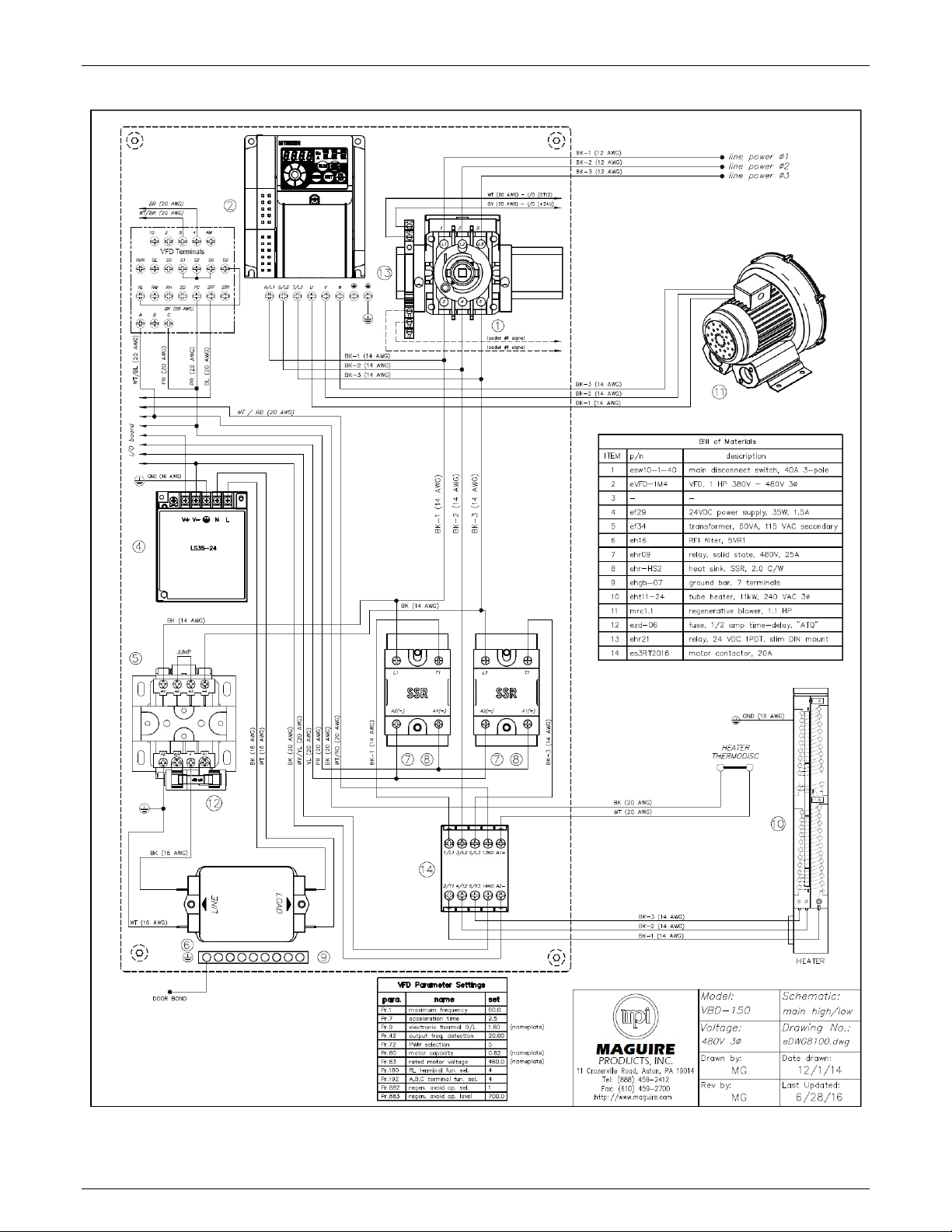
V
BD® - Vacuum Dryer®
Maguire Products, Inc.
VBD-150 480V Wiring Diagram with VFD
80
Rev. August 31, 2016 – VBD-150
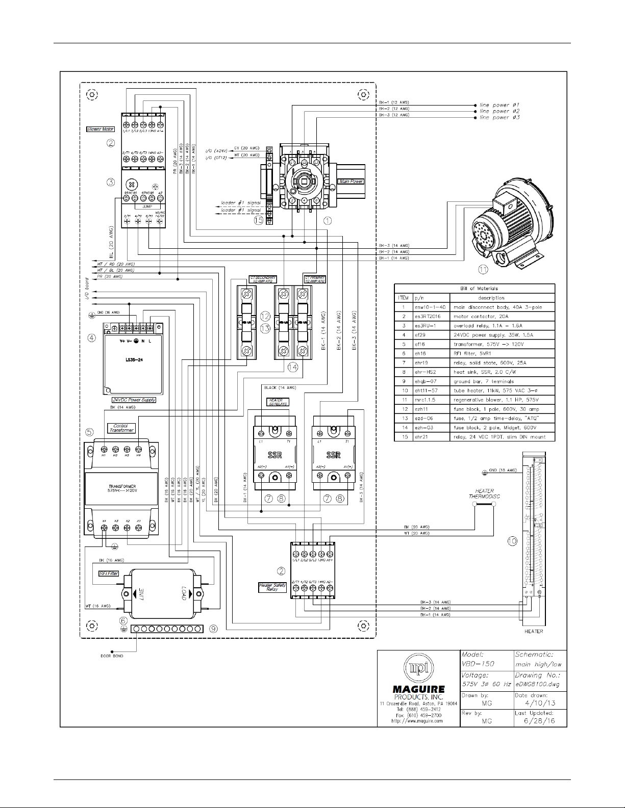
V
BD® - Vacuum Dryer®
Maguire Products, Inc.
VBD-150 575V Wiring Diagram
Rev. August 31, 2016 – VBD-150
81

V
BD® - Vacuum Dryer®
Maguire Products, Inc.
Pneumatic Diagram
82
Rev. August 31, 2016 – VBD-150

V
BD® - Vacuum Dryer®
Maguire Products, Inc.
Recommended Spare Parts List
Note: it is recommended that items #1 - #8 be kept on hand by the maintenance department.
line item MPI p/n Description General Location
1 8124-11 silicone seal, vacuum chamber dump valve vacuum chamber
2 go-349V o-ring, size 349, Viton upper vacuum gate
3 go-341V o-ring, size 341, Viton lower vacuum gate
4 as8124-03 vac. seal plate assy., vac. cham. dump valve lower vacuum gate
5 nv88 solenoid valve segment, 4-way, 24 VDC main cabinet
6 nf-30E filter element, for "AW30" series regulator pneumatics cabinet
7 nfos-2E filter element, for oil separator pneumatics cabinet
Other Potential Replacement Parts
8 esCGT1.0 overload relay, .63 A - 1.0 A electrical cabinet
9 esCGT1.6 overload relay, 1.0 A - 1.6 A electrical cabinet
10 esCGMS9D motor contactor, 3 pole, 20A, 24 VDC electrical cabinet
11 ehr09 relay, SS, 480V 25A, 24-265 VAC signal electrical cabinet
12 ezd-.5t fuse, 1/2 amp time delay, Midget style electrical cabinet
13 asRTDV1-1 RTD w/ 4-pin connector, heating hopper inlet heating hopper
14 asRTDV1-2 RTD w/ 5-pin connector, heating hopper outlet heating hopper
15 elc30V load cell, 30 kg capacity ret., vac. chamber
16 esp-50 pressure switch, 50 psi set-point, 1/8" NPT main cabinet
17 eabVBD-01 I/O circuit board electrical cabinet
18 eabVBD-03 display / HMI circuit board front control panel
19 eabVBD-04 pendant circuit board (.8" 4-digit numeric) front control panel
20 nmd-01E replacement element, for membrane air dryer pneumatics cabinet
21 eht11-24 tube heater, 11,000 watt 3 phase 240 VAC main cabinet
22 eht11-40 tube heater, 11,000 watt 3 phase 400 VAC main cabinet
23 eht11-48 tube heater, 11,000 watt 3 phase 480 VAC main cabinet
24 eht11-56 tube heater, 11,000 watt 3 phase 575 VAC main cabinet
25 ehsl-02 strobe light, red, magnetic base, 24VDC top deck
26 ehb-2 piezo buzzer, 24VDC front control panel
27 esh-01 interlock handle, red/yellow pistol front control panel
Rev. August 31, 2016 – VBD-150
83

V
BD® - Vacuum Dryer®
Technical Support and Contact Information
Maguire Products Inc.
11 Crozerville Road
Aston, PA 19014
Tel: 610.459.4300
Fax: 610.459.2700
Email: info@maguire.com
Web: www.maguire.com
Maguire Europe
Tame Park
Tamworth
Staffordshire
B775DY
UK
Tel: + 44 1827 265 850
Fax: + 44 1827 265 855
Email: info@maguire-europe.com
Maguire Products, Inc.
Maguire Products Asia PTE LTD
Main Office
15 Changi North Street 1
#01-15, I-Lofts
Singapore 498765
Tel: 65 6848-7117
Fax: 65 6542-8577
E-mail: magasia@maguire-products.com.sg
MAGUIRE ITALIA SRL
Via Cile, 14
35127 Padova
ITALY
TEL +39 049 970 5429
FAX +39 049 971 1838
Email: italia@maguire-europe.com
84
Rev. August 31, 2016 – VBD-150
 Loading...