

Maguire Products VBD-1000 Maintenance Manual

MAGUIRE PRODUCTS INC.
Vacuum Batch Dryer - VBD-1000
Touchscreen Controller
INSTALLATION OPERATION MAINTENANCE
Rev. March 5, 2018
VBD-1000
Vacuum Batch Dryer
Touch Screen Controller
Copyright Maguire Products, Inc. 2018

VBD
- Vacuum Dryer
Maguire Products, Inc.
2
Rev. March 5, 2018 – VBD-1000 Touchscreen

VBD
- Vacuum Dryer
Maguire Products, Inc.
VBD-1000 - Vacuum Dryer
This document is the Original Instructions manual of the Maguire VBD-1000 Vacuum Dryer
equipped with the Touchscreen Controller.
Copyright 2018 Maguire Products Inc.
The information contained within this manual including any translations thereof, is the property of
Maguire Products Inc. and may not be reproduced, or transmitted in any form or by any means
without the express written consent of Maguire Products Inc.
To every person concerned with use and maintenance of the Maguire VBD-1000 it is
recommended to read thoroughly these operating instructions. Maguire Products Inc. accepts no
responsibility or liability for damage or malfunction of the equipment arising from non-observance
of these operating instructions.
To avoid errors and to ensure trouble-free operation, it is essential that these operating
instructions are read and understood by all personnel who are to use the equipment.
Should you have problems or difficulties with the equipment, please contact Maguire Products
Inc. or your local Maguire distributor.
These operating instructions only apply to the equipment described within this manual.
Manufacturer’s Contact Information
Maguire Products Inc.
11 Crozerville Road
Aston, PA. 19014
Phone: 610.459.4300
Fax: 610.459.2700
Website: http://www.maguire.com
Email: info@maguire.com
Rev. March 5, 2018 – VBD-1000 Touchscreen
3

VBD
- Vacuum Dryer
Accuracy of this Manual
Maguire Products, Inc.
We make every effort to keep this manual as correct and current as possible.
However, technology and product changes may occur more rapidly then the
reprinting of this manual. Generally, modifications made to the dryer design or to
the operation of the software are may not reflected in the manual for several
months. The date at the footer of this manual will indicate approximately how
current this manual is. Likewise, your Dryer may have been produced at an
earlier time and the information in this manual may not accurately describe your
Dryer since this manual is written for the current line of Dryers in production (as of
the date in the footer). We always reserve the right to make these changes
without notice, and we do not guarantee the manual to be entirely accurate. If you
question any information in this manual, or find errors, please let us know so that
we may make the required corrections or provide you with accurate information.
Additionally, we will gladly provide you with an updated copy of any manuals you
need at any time. We welcome comments and suggestions on ways we can
improve this manual.
For additional information, or to download the latest copy of this manual or any
other Maguire manual, please visit our website or contact us directly.
On the Web at: www.maguire.com
Maguire Products Inc.
Main Headquarters
11 Crozerville Road
Aston, PA 19014
Tel: 610.459.4300
Fax: 610.459.2700
info@maguire.com
Maguire Europe
Tame Park
Tamworth
Staffordshire
B775DY
UK
Tel: + 44 1827 265 850
Fax: + 44 1827 265 855
info@maguire-europe.com
Maguire Products Asia PTE LTD
15 Changi North Street 1
#01-15, I-Lofts
Singapore 498765
Tel: 65 6848-7117
Fax: 65 6542-8577
magasia@maguire-products.com.sg
Maguire Imea Fzco India, Middle East & Africa
Lobby 18, Floor 7, Office 6
JAFZA View 18Jebel Ali Downtown
PO Box 17493, Dubai, UAE
Tel: +971 4 881 6700
info@maguire-imea.com
Maguire Canada
299 Basaltic Road, Unit 1
Vaughan, Ontario L4K 4W8,
CANADA
Toll Free: 866-441-8409
Tel: 905-879-1100
Fax: 905-879-1101
info@maguirecanada.com
Please e-mail comments and suggestions to: support@maguire.com
4
Rev. March 5, 2018 – VBD-1000 Touchscreen

VBD
- Vacuum Dryer
Maguire Products, Inc.
Table of Contents
INSTALLATION 8
Dryer Assembly 12
Engaging the Load Cells 15
Dryer Connections 19
Compressed Air Connection 19
Electrical Connection 20
Home Screen Overview 22
Setup Menu Map -Brief Explanation 30
Parameters Explained 41
Changing Parameters 49
Batch Mode 50
Communication Setup 51
Operation 23
Start Up and Operation Instructions 23
What is happening when the Dryer is Running 25
Shutdown – Immediate or Planned 26
Recommended Drying Temperatures 29
Maintenance 53
Drain and purge Air Filter / Regulator 53
Air Pressure Adjustments 53
Cleanout Procedure 57
Loadcell Calibration 54
Alarms - Cause and Solution 61
Logs and Print Outputs 67
Dryer Firmware Updates 73
General Information 74
Technical Specifications 77
Theory of Operation / Performance 77
Warranty 78
Recommended Spare Parts List 79
Wiring Diagrams 80
Declaration of Conformity 84
Technical Support / Contact Information 85
Rev. March 5, 2018 – VBD-1000 Touchscreen
5

VBD
- Vacuum Dryer
Warranty – Exclusive 5-Year
MAGUIRE PRODUCTS OFFERS THE MOST
COMPREHENSIVE WARRANTY in the plastics
auxiliary equipment industry. We warrant each
MAGUIRE VBD Vacuum Dryer manufactured by us to
be free from defects in material and workmanship under
normal use and service; excluding only those items
listed below as 'excluded items'; our obligation under
this warranty being limited to making good at our
factory any Dryer which shall, within FIVE (5) YEARS
after delivery to the original purchaser, be RETURNED
intact to us, transportation charges PREPAID, and
which our examination shall disclose to our satisfaction
to have been thus defective; this warranty being expressly in lieu of all other warranties
expressed or implied and of all other obligations or liabilities on our part, and MAGUIRE
PRODUCTS neither assumes nor authorizes any other persons to assume for it any
other liability in connection with the sale of its Dryers.
This warranty shall not apply to equipment repaired or altered outside MAGUIRE
PRODUCTS INC. factory, unless such repair or alteration was, in our judgment, not
responsible for the failure; nor which has been subject to misuse, negligence or
accident, incorrect wiring by others,
or installation or use not in accord with instructions furnished by
Maguire Products, Inc.
Our liability under this warranty will extend only to equipment that is returned to our
factory in Aston, Pennsylvania, PREPAID.
Please note that we always strive to satisfy our customers in whatever manner is
deemed most expedient to overcome any problems they may have in connection with
our equipment.
Maguire Products, Inc.
GETTING STARTED:
PROCEED TO: SAFETY WARNINGS NEXT PAGE
6
Rev. March 5, 2018 – VBD-1000 Touchscreen
VBD
- Vacuum Dryer
SAFETY WARNINGS
Maguire Products, Inc.
HOT SURFACES:
As with all dryers, there are HOT
SURFACES to avoid. Temperatures can
reach 350F, (180C).
Typically, these surfaces are not at dangerous
temperatures, however all hot surfaces should be avoided.
Warning Label indicate:
HOT SURFACES
USE CAUTION when removing
and installing canisters.
USE GLOVES
DO NOT REACH into the dryer
enclosure.
RISK OF SHOCK:
Disconnect power supply before
servicing the Dryer.
GETTING STARTED: PROCEED TO: INSTALLATION - NEXT PAGE
Rev. March 5, 2018 – VBD-1000 Touchscreen
7
VBD
- Vacuum Dryer
material to be convey from the base of the VBD Dryer.
Maguire Products, Inc.
Installation
Transport and Setup
Shipment
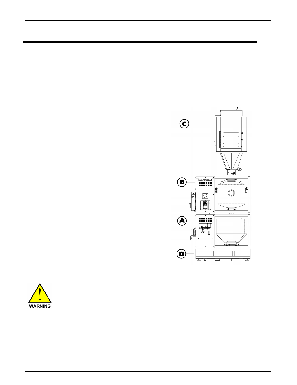
The VBD-1000 Dryer is shipped as separate components that require re-assembly.
The 3 main sections are:
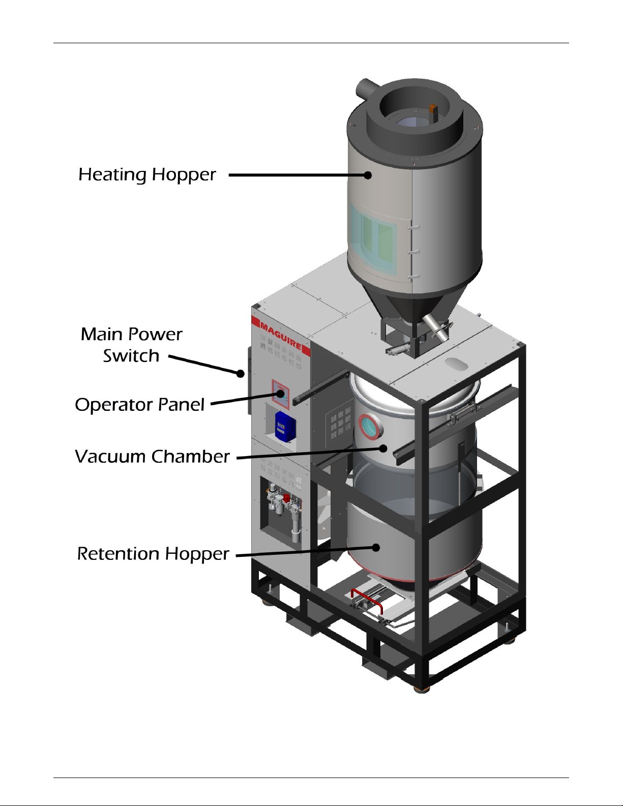
Retention Hopper Assembly (A) – Identified by the
recessed pneumatics cabinet on the front panel and
the removable Retention Hopper on the lower slide
rail. Weight is 1920 lb (871 kg)
Vacuum Chamber Assembly (B) – Identified by the
control panel on the front panel, the electrical cabinet
on the left side and the hanging vacuum chamber.
Weight is 1920 lb (871 kg).
Heating Hopper Assembly (C) – Identified as a tall
heating hopper. Weight is 350 lb (159 kg)
Optional Base Frame (D) – a sub frame that elevates
the Retention Hopper Assembly 16 inch allowing
Weight of the Base Frame is 1303 lb (591 kg)
Other smaller components will be included. An
optional mounting base section may be included.
Lifting and Moving components of the Dryer
Ensure your lifting equipment is rated to lifting the weight
of the individual sections of the VBD-1000.
The three main sections of the VBD-1000 Dryer are shipped with Forged Eye Bolts to be
used specifically as lifting points. When lifting the Retention Hopper Assembly (A) and the
Vacuum Chamber Assembly (B), utilize all 4 Forged Eye Bolts to distribute the weight
evenly. The Retention Hopper Assembly uses two Forged Eye Bolts and should be lifted
using both Forged Eye Bolts. The Forged Eye Bolts must be removed from the
Retention Hopper Assembly (A) BEFORE lowering the Vacuum Chamber Assembly (B)
into place.
8
Rev. March 5, 2018 – VBD-1000 Touchscreen
VBD
- Vacuum Dryer
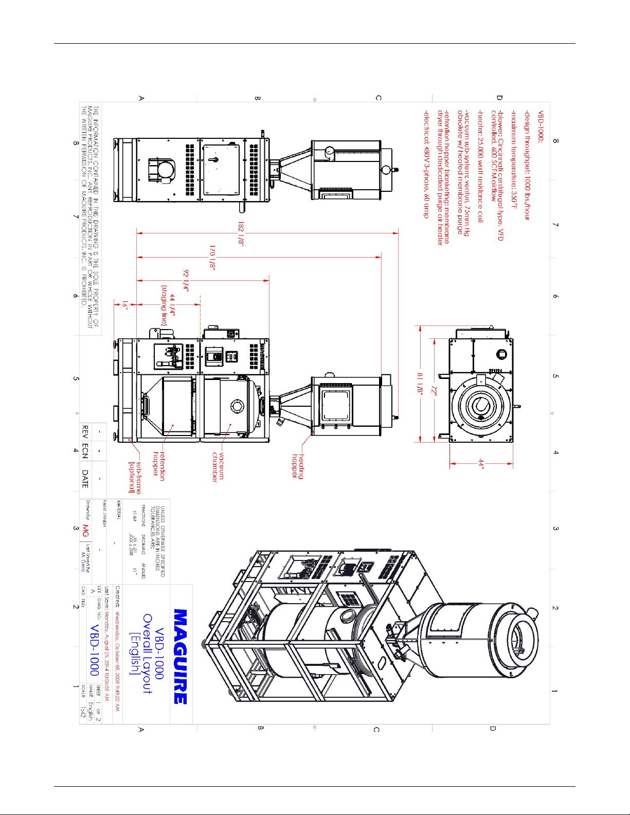
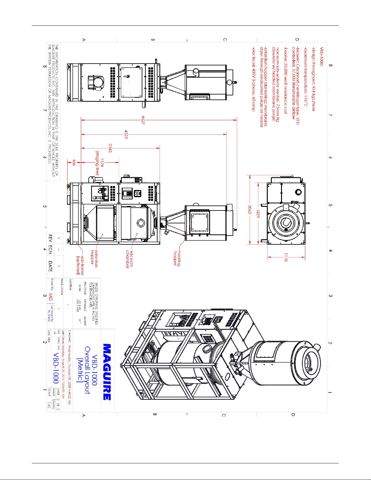
Overall layout and Dimensions
Maguire Products, Inc.
Rev. March 5, 2018 – VBD-1000 Touchscreen
9
VBD
- Vacuum Dryer
Maguire Products, Inc.
10
Rev. March 5, 2018 – VBD-1000 Touchscreen
VBD
- Vacuum Dryer
Maguire Products, Inc.
Rev. March 5, 2018 – VBD-1000 Touchscreen
11
VBD
- Vacuum Dryer
Dryer Assembly
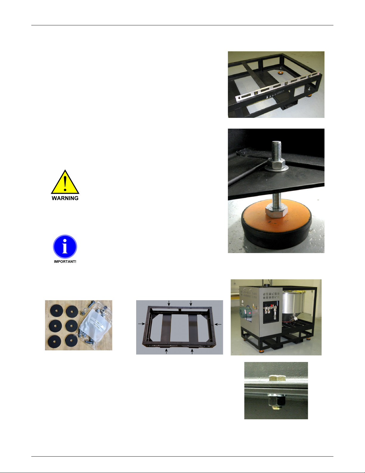
Optional Base Frame
The Base Frame is used to raise VBD’s Retention
Hopper off of the floor. Weight of the Base Frame is
1303 lb (591 kg). Note: If the VBD is to be installed so
that material is gravity fed out of the bottom of the
Dryer, then this Base Frame is not necessary.
Level the Base Frame - If the Base Frame is to be used,
it must be leveled at the installation location. The Base
Frame of the VBD 1000 can be leveled two different
ways. Leveled using the 4 leveling feet or by shimming
the frame to the floor.
If using the leveling feet, make sure
the surface that the VBD 1000 will
be install on can support the weight
of the VBD at 4 corners. If the floor
cannot support this weight in 4
small footprints, use leveling shims
on the frame, not the leveling feet.
When adjusting the leveling feet,
keep the frame as close to the floor
as possible. Over extending the
threads below the frame is not
recommended for stability reasons.
Maguire Products, Inc.
Installing Retention Hopper Assembly (Section A)
Set the 6 spacers at the locations shown below.
If using the Base Frame, lower the Retention Hopper
Assembly onto the Base Frame. Secure the Retention
Hopper Assembly to the Base Frame using the supplied
hardware. The Retention Hopper Assembly is secured
to the Base Frame using (10) 1/2-13 grade 8 bolts.
If the Base Frame is not used – Lower the Retention
Hopper Assembly (Section A) into place. The
Retention Hopper Assembly must be leveled BEFORE
installing the next section.
12
Rev. March 5, 2018 – VBD-1000 Touchscreen
VBD
- Vacuum Dryer
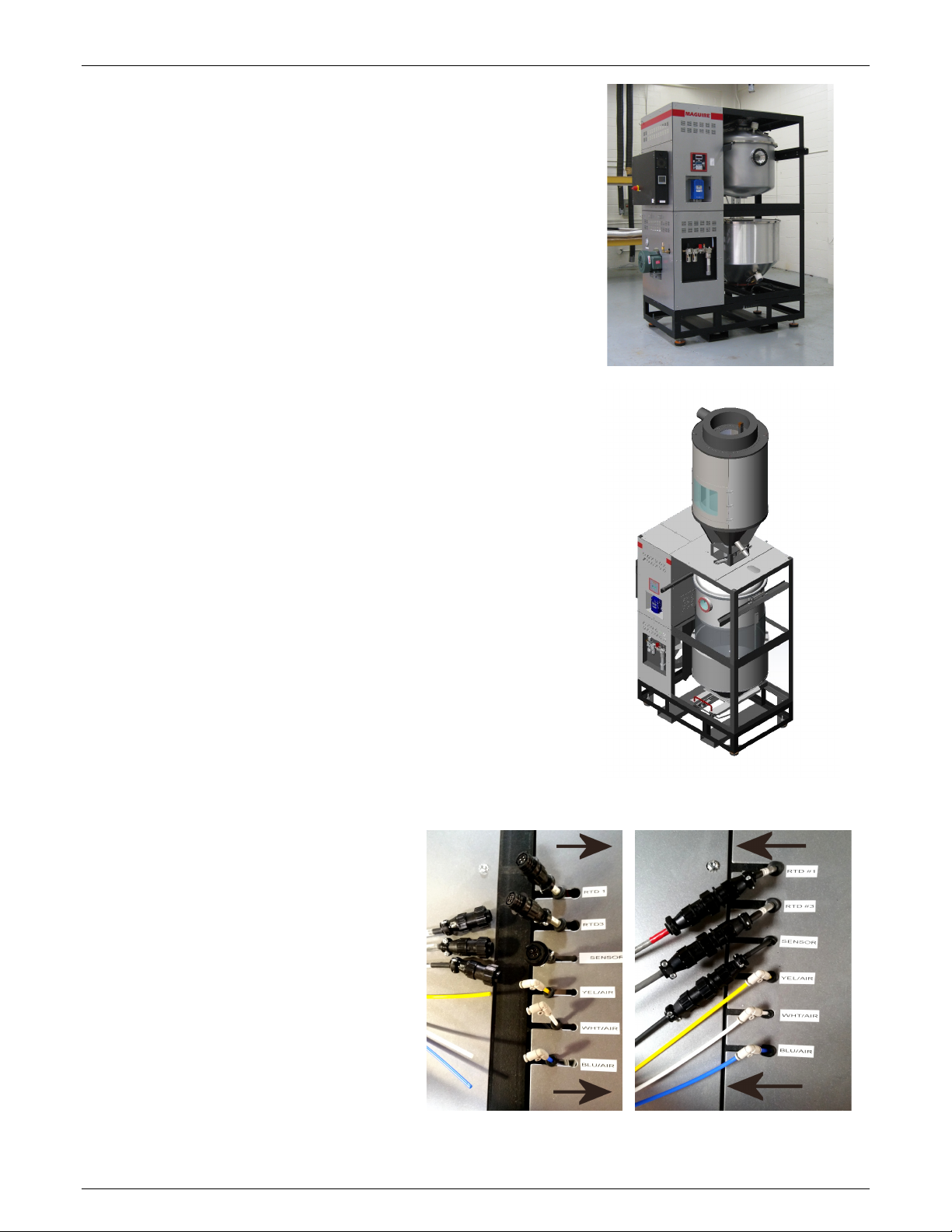
Installing Vacuum Tank Assembly
(Section B)
Lower the Vacuum Tank Assembly (Section B) onto
the Retention Hopper Assembly. Align the enclosed
side of each section (as shown in image at right). Align
the bolt holes of each section.
Remove the rear panels of Retention Hopper Assembly
(A) and Vacuum Tank Assembly (B) to gain access to
the connections that need to be made within the
enclosure. Install the 10 1/2-13 grade 8 bolts and
tighten.
Install the Heating Hopper
Raise the Heating Hopper on top of section B of
the VBD dryer.
Position the Hopper so that the front hatch faces
the same side of the dryer as the VBD’s control
panel.
Install the 10 1/2-13 grade 8 bolts and tighten.
Maguire Products, Inc.
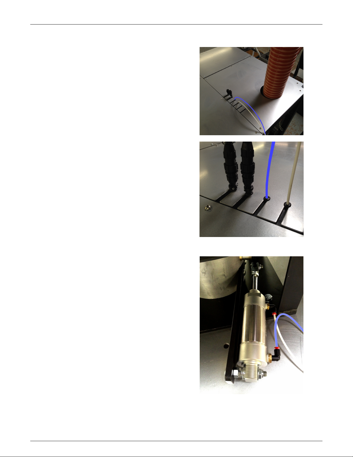
Connect RTD Sensors and Air Lines
After installing the Heating Hopper,
located the upper sheet metal panel
with the slotted holes. Remove the
button head screws and bring the three
air lines and 3 sensor cables through
the slotted holes. Each sensor cable is
labeled for the specific slots. Air lines
are labeled yellow, white and blue.
Also bring the rubber grommets
through the sheet metal and install the
grommets in the slot to protect the
wires and air lines. Connect the air
lines, Connect the sensor cables and
reinstall the sheet metal panel.
Rev. March 5, 2018 – VBD-1000 Touchscreen
13
VBD
- Vacuum Dryer
Installing the Upper Vacuum Gate
Note: If your Upper Vacuum Slide Gate is already
installed from factory, skip this step.
If the VBD-1000 Upper Vacuum Gate was shipped
detached from the VBD-1000 it must be installed
after the Heating Hopper is installed.
Items with this assembly:
Upper Vacuum Gate
Retainer Bracket
two 1/4-20 1/2" button head screws
The Upper Vacuum Gate will install from the rear
of the Dryer. Locate the slot on the mount ring at
the very top of the Vacuum Tank. See photo at
right.
Maguire Products, Inc.
With the Slide Gate facing up, slide the Upper
Vacuum Gate assembly into the slot on the mount
ring as shown in the photo to the right. Slide the
Upper Vacuum Gate onto the mount ring until it
fully seats into the slot. It may be helpful to slide
the Upper Vacuum Gate left and right as it is
installed.
Note: To fully seat the Vacuum
Gate onto the mount ring, the tab
in the inner arch of the Upper
Vacuum Gate must go into the
recessed hole of the mount ring
on the Vacuum Chamber.
From the front side of the Dryer, install the
Retaining Bracket onto the Upper Vacuum Gate
and fully into the slot on the mount ring and
secure it using the two 1/4-20 1/2" button head
screws.
Install the two 5/32 (4mm) airlines onto the Upper
Vacuum Gate air cylinder. The shorter line will
connect to the air cylinder fitting closest to the
slide gate.
14
Rev. March 5, 2018 – VBD-1000 Touchscreen
VBD
- Vacuum Dryer
Engaging the Load Cells
The Load cells are disengaged for shipping and must be engaged for
proper operation of the VBD-1000 Dryer. There are two sets of load cells:
the Vacuum Chamber load cell and the Retention Hopper load cell pair.
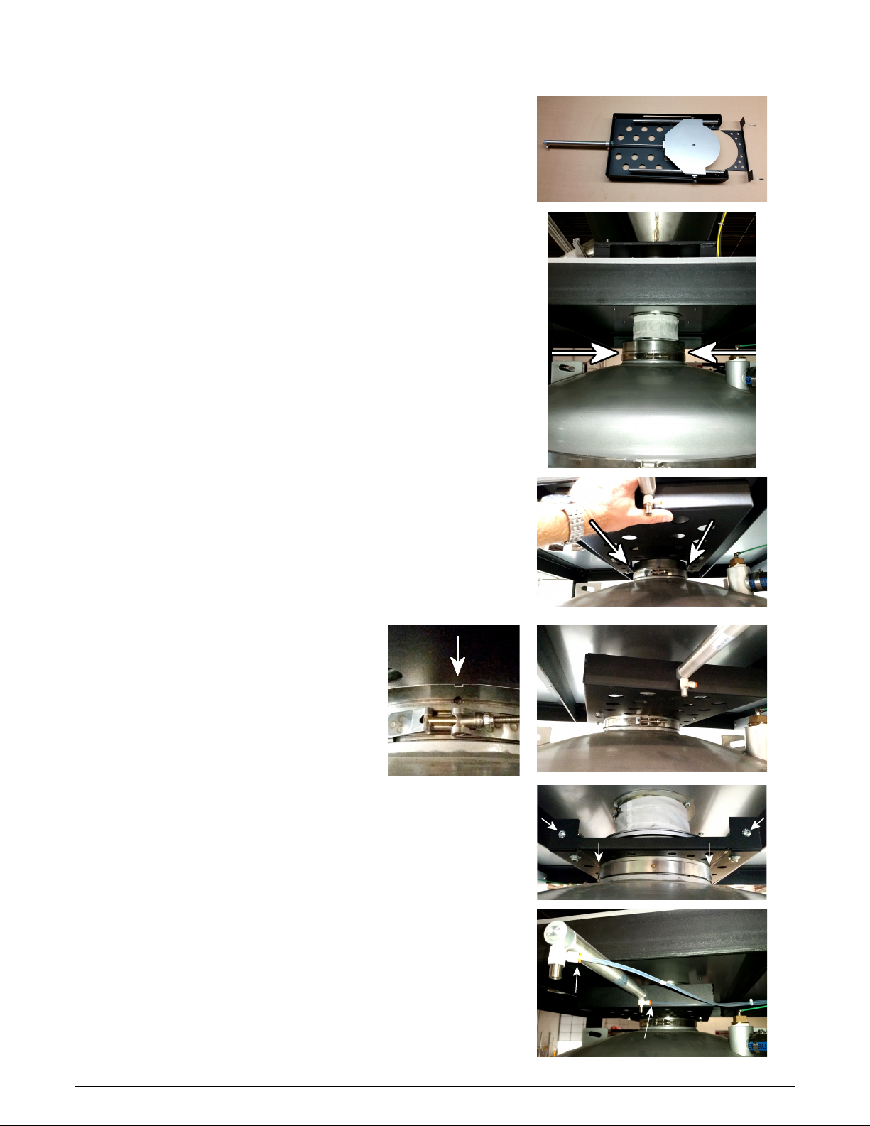
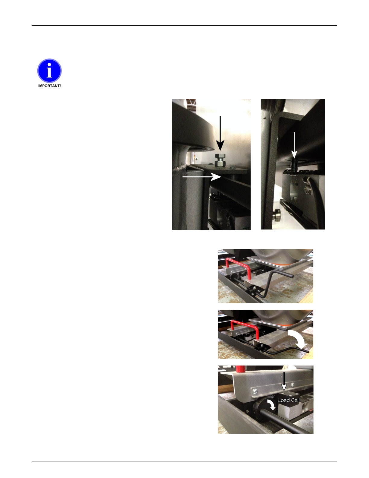
Vacuum Chamber Load Cell
The Vacuum Chamber load cell is
located between the Vacuum
Chamber and the Vacuum Chamber
Assembly (B).
To engage the load cell, turn the load
cell lifting bolt down until it engages
the load cell located below. Continue
turning until the Vacuum Chamber
hanger is lifted 1/4 inch (6mm) off of
the sliding rail.
Maguire Products, Inc.
Retention Hopper Load Cell Pair
The Retention Hopper load cell pair is located
in front of and below the Retention Hopper.
To engage the Retention Hopper load cell pair,
remove the packaging straps from the
Retention Hopper Lifting Lever. Lower the
Retention hopper onto the load cell by pressing
the lever back and down. This will engage the
Retention Hopper lower frame onto the load
cell pair.
When the Retention Hopper Lifting Lever is in
its upright position, the lever's cams lift the
weigh off of the load cell pair and allow the
Retention Hopper to be pulled out for servicing
and cleaning purposes.
Lifting bolt, 1/4" (6mm) gap
Engage load cell
Rev. March 5, 2018 – VBD-1000 Touchscreen
15
VBD
- Vacuum Dryer
Heating Hopper Dump Valve Air Lines
There is one white and one blue 5/32 inch air
line, two RTD thermometer cables and one
sensor wire (not pictured) bundled within the
VBD-1000 enclosure for safety during
shipping of the VBD-1000. The air lines and
cables must be brought through the enclosure
using the predrilled slotted keyholes. in the
top panel.
To install remove the top panel and locate the
air lines and RTD thermometer cables. On
each air line and wire is a rubber grommet.
Slide the rubber grommet into the slotted
keyhole in the sheet metal, then re-install the
top panel.
Maguire Products, Inc.
Test air line orientation: connect air supply
to VBD-1000. With the VBD power turned off,
the air cylinder should be extended as shown
in photo to the right. Air cylinder is extended
closing the butterfly valve inside the base of
the hopper.
16
Rev. March 5, 2018 – VBD-1000 Touchscreen
VBD
- Vacuum Dryer
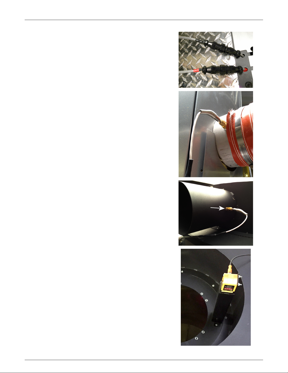
Connect RTD Thermometers
The RTD thermometer cables are terminated on one
end with a CPC connector. The Inlet RTD cable is
marked with a red band. This is the shorter of the two
cables. Connect the cables as shown with the red
banded cable connecting to the CPC connector with
the matching red band.
Secure the Heating Hopper Inlet RTD thermometer to
the side heat inlet of the heating hopper. Secure the
cable to frame of the heating hopper.
Maguire Products, Inc.
Route the longer RTD thermometer cable up to the
exhaust port on the top of the heating hopper and
secure the RTD thermometer as shown. Secure the
cable to frame of the heating hopper.
Install Heating Hopper Level Sensor and Bracket
Install the Heating Hopper bracket and sensor on top
of Heating Hopper (as shown). Located the sensor
cable that exits the top of the VBD Heating Hopper
and attach the sensor cable to the sensor.
Rev. March 5, 2018 – VBD-1000 Touchscreen
17
VBD
- Vacuum Dryer
Maguire Products, Inc.
Dryer Internal Assembly
If your Dryer has been shipped with the Retention Hopper Assembly and
the Vacuum Tank Assembly together as one shipment (sections A and B
in the diagrams), then the Dryer Internal Assembly instructions are not
necessary as they are pre-assembled.
Remove the rear panels of Retention Hopper Assembly (A) and Vacuum Tank Assembly
(B) to gain access to the connections that need to be made within the enclosure.
Summary of internal connections:
Heating Hopper Heater connected to blower outlet.
Power Junction Box Plug
Purge Air Solenoid Valve Electrical Plug
Electrical Field Joints (Color Coded)
¾ inch Purge Line
5/32 inch air lines
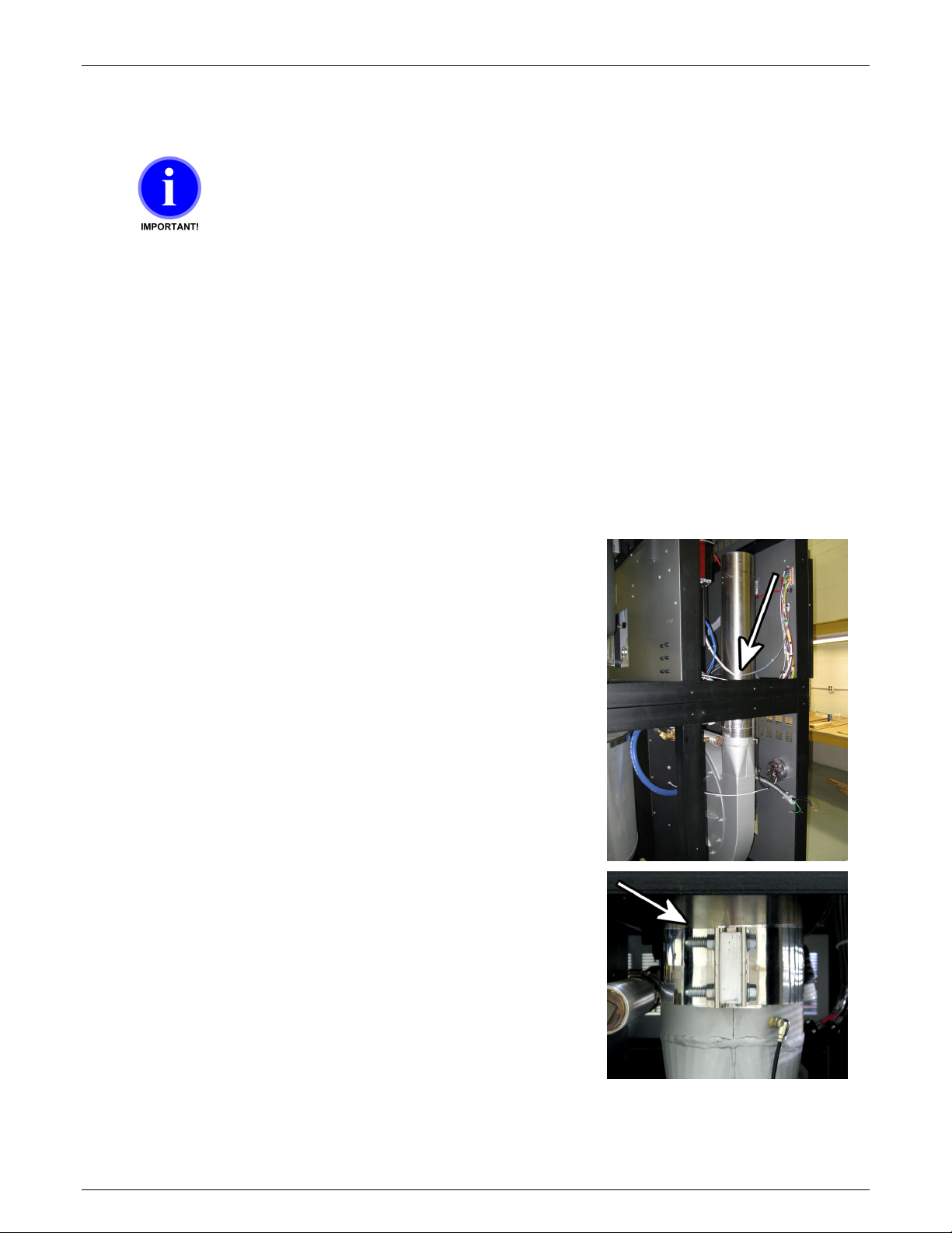
Install the Heating Hopper Heater
The Heater a polished steel 6-inch cylinder that is prewired and secured within the cabinet during shipping.
This heater must be attached to the outlet of the blower
using the attached 6-inch clamp. First loosen the clamp
attached to the blower’s output. Leave the clamp on the
blower. Then remove the shipping material securing the
Heating Hopper Heater.
Carefully rest the Heater on top of the blower output so
that the heater rests directly on the blower’s 6-inch
output. Tighten the clamp firmly to secure the Heater to
the blower.
18
Rev. March 5, 2018 – VBD-1000 Touchscreen
VBD
- Vacuum Dryer
Maguire Products, Inc.
Dryer External Connections
Once assembled, installation requires electrical, pneumatic air line connection and intake and
output material lines to be connected.
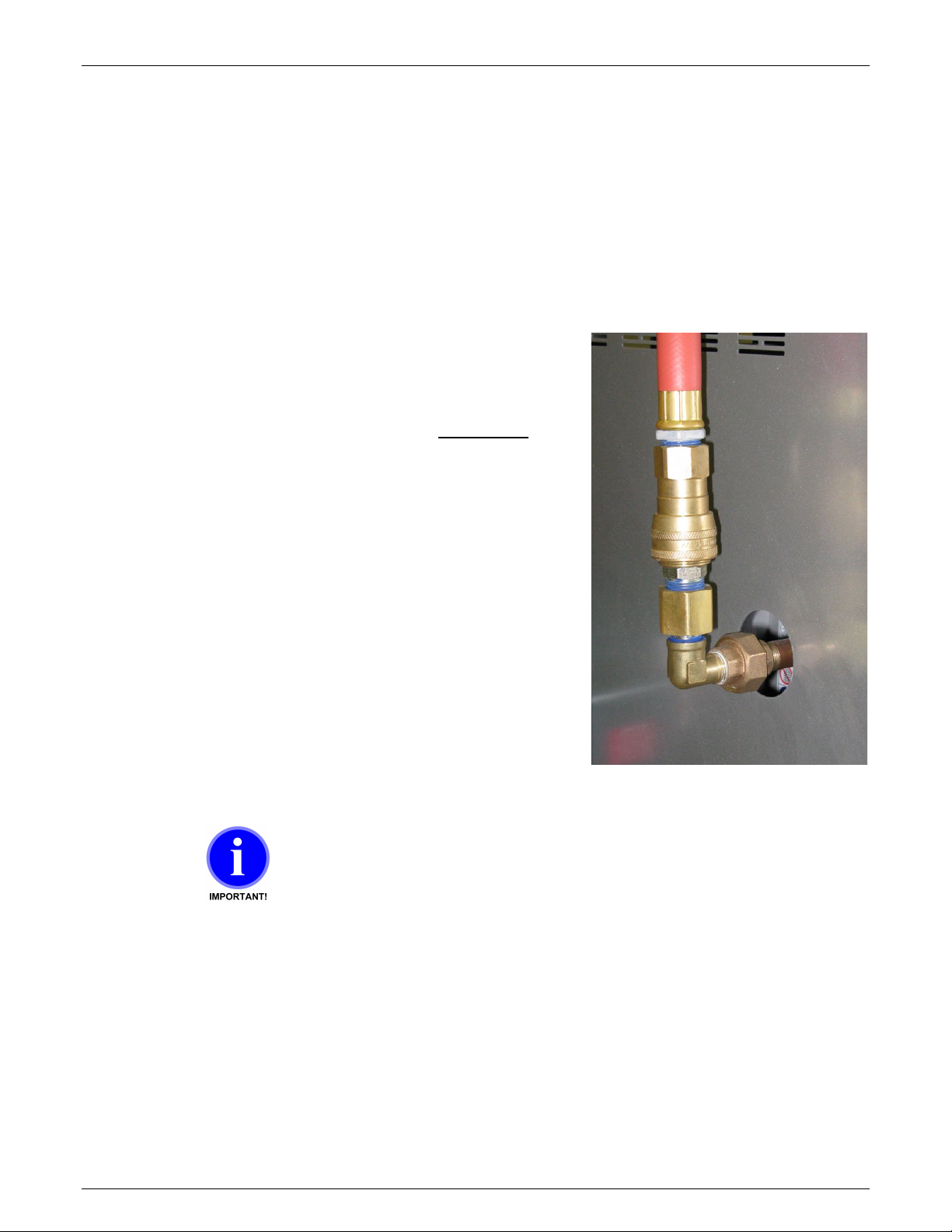
Compressed Air Connection
Connect an air supply to the air regulator’s IN
port using a male 1/2 ” NPT fitting.
An operating air pressure of 80 psi (5.5 bar)
while the vacuum generator is running is
required for proper operation of the Dryer.
If your air supply has oil in it, add an oil
separator (coalescing filter).
Oil in the air will combine with dust drawn from
the vacuum tank forming a paste inside the
vacuum generator. It will stop working and
require cleaning.
Observe the air pressure gauge to be sure the
pressure maintains 80 psi (5.5 bar) while the
vacuum generator is running as you check and
adjust the regulator. If pressure drops below
80 psi, adjust the regulator. If the pressure
cannot be maintained at 80 psi (5.5 bar) while
the vacuum generator is running, then the air
supply line is not adequate.
Do not supply Dryer with a lubricated air supply.
Damage to Dryer may result. Use only a clean,
dry, oil-free air supply.
Rev. March 5, 2018 – VBD-1000 Touchscreen
19
VBD
- Vacuum Dryer
or
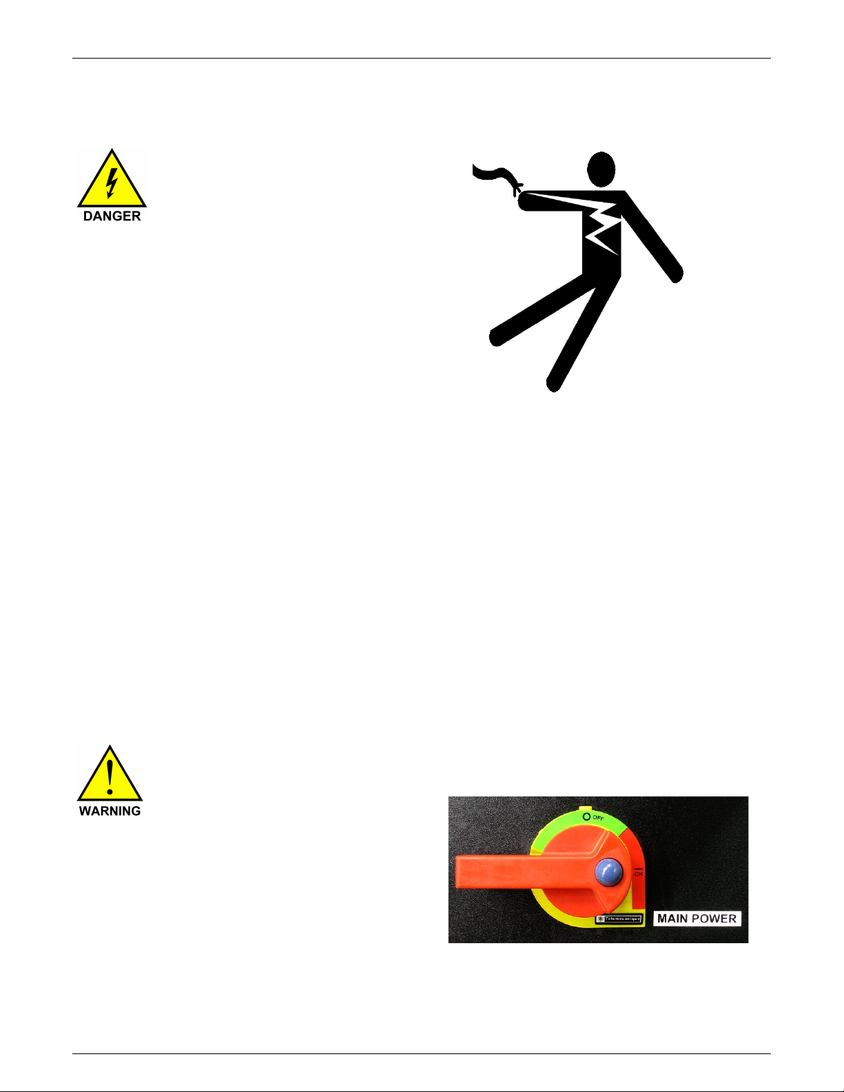
Electrical Connection
Maguire Products, Inc.
RISK OF INJURY!
Only qualified
technicians should
make electrical
connections.
Connect Main Power
The electrical cable located on the left side of the Dryer on the power
box supplies the power to the Dryer. Within the cable is four wires.
Three of the wires are black and labeled with a number: 1, 2, and 3.
The fourth wire is a green/yellow wire and is the ground wire.
Connect power to a properly fused disconnect.
See page 81 for the High Voltage Wiring Diagram
THREE PHASE: 60 cycle 480 volts
50 cycle 400 volts
Confirm Correct 3-Phase Electrical Connection
THREE PHASE Unit - CONFIRM proper 3-Phase power connection
by following these instructions:
Turn power on using
main power switch.
On the outside of the electrical
box below the power switch is
a red 3-Phase indicator light.
If 3-Phase power is correctly
connected, the controller will
power up and the red indicator
light will NOT be lit.
20
Rev. March 5, 2018 – VBD-1000 Touchscreen
VBD
- Vacuum Dryer
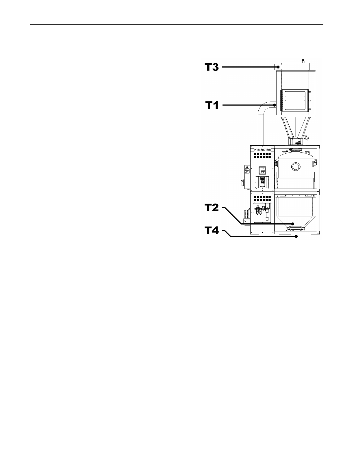
Temperature Sensor Locations
T1 – Heating Hopper Air Inlet
T1s – Heating Hopper Air Inlet Temperature Setting
T1a – Heating Hopper Air Inlet Temperature Actual
T2 – Dry Purge Air Temperature
T2s – Dry Purge Air Temperature Setting
T2a – Dry Purge Air Temperature Actual
T3 – Heating Hopper Air Outlet Temperature
T3s – Heating Hopper Air Outlet Temperature Setting
T3a – Heating Hopper Air Outlet Temperature Actual
T4 – Material Outlet Temperature (optional)
T4s – Material Outlet Temperature Setting
T4a – Material Outlet Temperature Actual
Maguire Products, Inc.
Rev. March 5, 2018 – VBD-1000 Touchscreen
21
VBD
- Vacuum Dryer
Home Screen
Maguire Products, Inc.
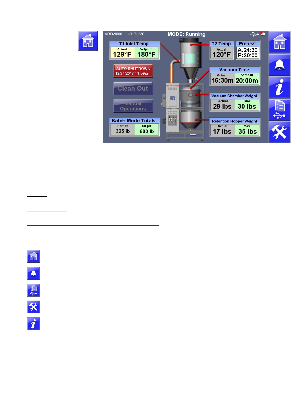
Overview
Shown with enabled options:
Auto Shutdown, Batch Mode,
and Preheat, VBD-1000 screen
T1 Actual - Actual Heating
Hopper inlet air temperature
T1 Setpoint - Heating Hopper
inlet air temperature Setpoint.
Touch to adjust.
T2 Temp – Actual Heating
Hopper temperature
Vacuum Time – Vacuum Time
Actual and Vacuum Time
Setpoint. Touch to adjust.
Vacuum Chamber Weight
Vacuum Chamber Actual and
Maximum Weight
Retention Hopper Weight
Actual and maximum weight
Preheat – Preheat Time Actual and Preheat Time Setpoint. Touch to adjust.
Info (i) - Access to advance information.
Additional information can be accessed by touching the Heating Hopper, Vacuum
Chamber and the Retention Hopper.
Title Bar - Located across the top of the screen, the title bar displays Model, ID, I/O status, current operating mode,
date and time, Ethernet and USB status.
Navigation Menu - Located along the right side of the screen, these buttons allow quick navigation to frequently used
and top level screens. The middle three buttons are soft buttons that can be changed or removed.
Start / Shutdown (Auto Shutdown shown above) Button - Main Start Stop Control Button of the Dryer.
Navigation Menu
Home Screen Pressing the Home Screen button from any other screen will return the
Alarm and
Event
Print Center A menu screen of print related options including Totals, Parameters,
Setup Login Password protected access to advanced Dryer and System configuration
Info Screen System Information including firmware versions, IP and MAC address
Run Dryer - See page 23
Clean Out – See page 57
Manual Operations - See page 30
Top Level Menu:
operator to the main Home Screen.
Alarm and Event Log displays a history of alarms and other events with a
date and time stamps and description.
Alarm History, Events, Cycle History, Diagnostics. See page 67.
information.
and machine operating tags.
22
Rev. March 5, 2018 – VBD-1000 Touchscreen
VBD
- Vacuum Dryer
Maguire Products, Inc.
Start Up and Operation
This section will help you understand what the dryer is doing during operation from a cold start.
There are 3 concurrent operations. Heating, Vacuum and, Retention. Cold startup begins with
Preheat. Preheat only occurs before the first cycle of the dryer’s initial startup, otherwise each
cycle begins with material heating. The vacuum operation pulls and holds a vacuum on the
material for at least the Vacuum Time Set-point (or longer if material remains in the Retention
Hopper). The Retention operation holds the dried material in the Retention Hopper, blanketing
the material with hot, dry air, until the material is conveyed away.
Important: Inspect the VBD, verify that machine is clear of all material from all tanks, heating
hopper, Vacuum Chamber and Retention Hopper. To facilitate a Clean Out, use the Clean Out
function accessible from the home screen.
Startup and Operation Instructions
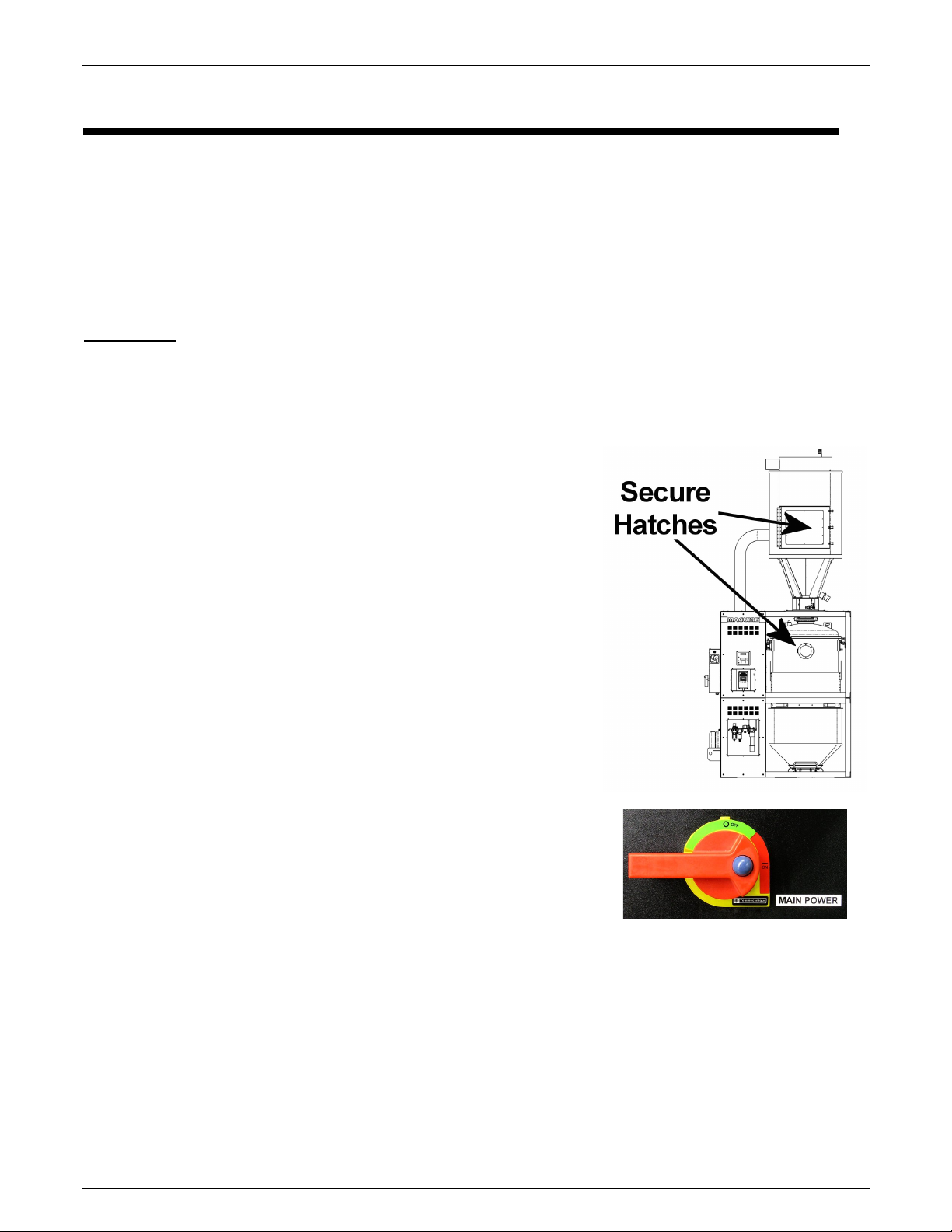
1. ENSURE HATCH IS CLOSED. There is a hatch
located on the upper Heating Hopper. Ensure all 3
latches are closed. Also be sure the removable
Lower Retention Hopper is in place.
2. Load material into the Upper Heating Hopper.
Wait for the Heating Hopper to fill with material before
starting the Dryer.
3. Turn on Main Power by rotating the 60 AMP Main
Disconnect Handle to the Red ON position. This
powers up the VBD-1000 Dryer.
On initial power up of the VBD, the Control Panel
powers ON automatically. If the main power is ON
but the Control Panel is OFF, press and hold the Red
Power Button located on the Control Panel for 2
seconds. (Note: The VBD’s Control Panel can be
powered OFF without powering down the Main Power
by pressing and holding the Red Power button for 4
seconds).
Rev. March 5, 2018 – VBD-1000 Touchscreen
23
VBD
- Vacuum Dryer
Maguire Products, Inc.
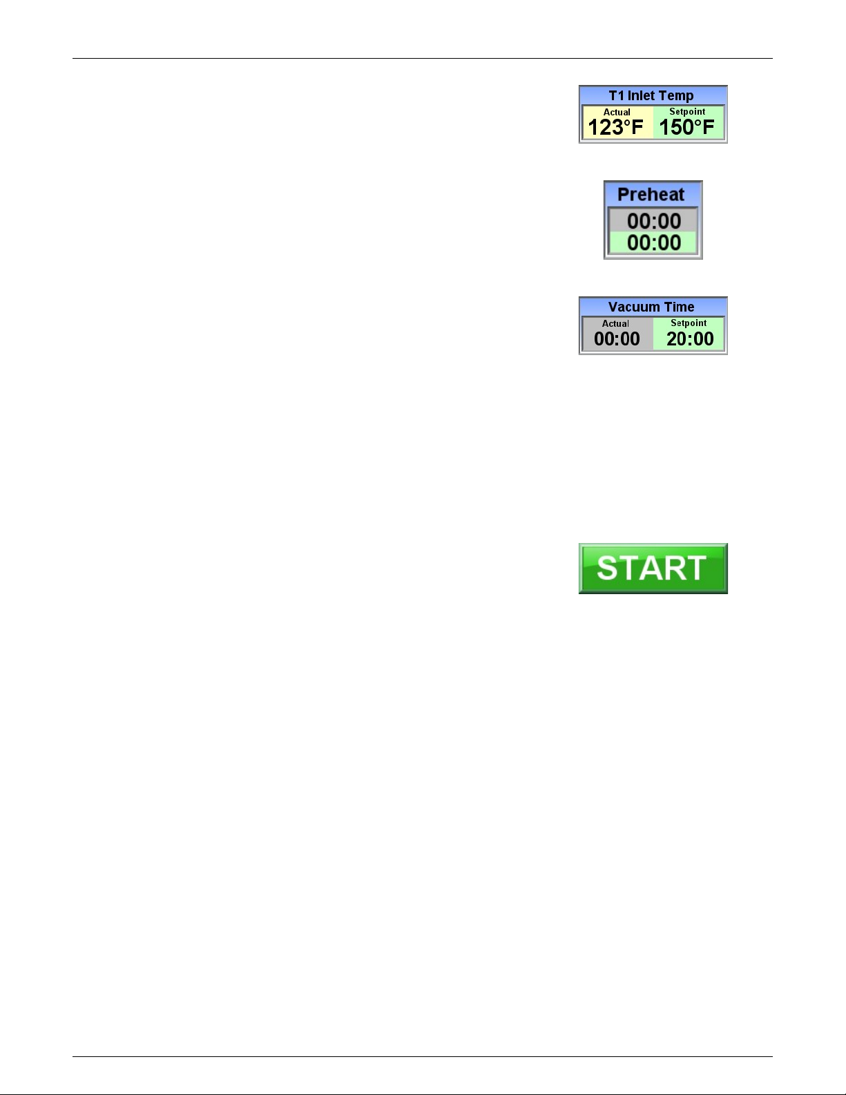
4. On the Home Screen:
T1 Inlet Temp Setpoint – This is heat hopper inlet
temperature. By the end of the preheat cycle time, all
material in the Heating Hopper will be heated to this
temperature. By default, the Setpoint temperature is
set to 150°F. Contact the material manufacturer for
temperature recommendations.
Preheat Time – This is the duration of heating from a
cold start.
Vacuum Time – This is the minimum duration of a
vacuum cycle. Actual vacuum cycle times will vary
according to the throughput. The default vacuum
time is 20 minutes. In the vast majority of drying
operations, this time is adequate and does not need
to be adjusted. Special circumstances may require
different vacuum times. Please consult a Maguire
Dryer Technical for additional information.
Press the setpoint field to adjust the setting. Use the
on-sceen keypad to enter the setpoint and press the
green check to complete the setting adjustment.
5. Press the START button to start the dryer.
6. The display will show that the dryer is running in
PREHEAT
mode and display the following:
T1 Actual - Actual Heating Hopper inlet air
temperature
T1 Setpoint - Heating Hopper inlet air temperature
Setpoint.
T2 Temp – Actual Heating Hopper temperature
Vacuum Time – Vacuum Time Actual and Vacuum
Time Setpoint.
Vacuum Chamber Weight - Vacuum Chamber
Actual/Maximum Weight.
7.
24
Rev. March 5, 2018 – VBD-1000 Touchscreen

VBD
- Vacuum Dryer
Maguire Products, Inc.
What is happening when the dryer is running:
During the Pre-heat operation material in the heating hopper is brought up to temperature
(T1s). Preheat time is determined by the specified Preheat Time on the Pre-Start screen
(timed preheat, default 60 minutes) or by the Preheat Setup Auto option, which sets an inlet
to outlet temperature delta and a minimum preheat time.
After pre-heat, approximately one third of the material in the heating hopper is dispensed
into vacuum chamber, and the first vacuum cycle begins. Each vacuum cycle has a
minimum vacuum time, set on the Pre-start screen, or the main run screen (VTs). (default
is 20 minutes).
The loader loads the Heating Hopper with new material as the Vacuum Chamber receives
the heated material and heating cycle begins concurrent to vacuum cycle (the first vacuum
cycle is timed). The new batch of material in the upper portion of the heating hopper will
take less time to heat. Minimum time in the heating is dictated vacuum time.
After first vacuum cycle, material is then dispensed into retention hopper ready for use.
Material in the retention hopper is blanketed with dry air.
The rate of consumption of dried material from the retention hopper ultimately dictates the
amount of time that the material will be preheated and under vacuum. Examples: If it
takes 30 minutes to deplete the retention hopper, the vacuum cycle will run past its 20
minute setpoint (pre-start screen) to 30 minutes. This is normal operation. However if the
retention hopper is depleted in 15 minutes and the vacuum time is set to 20 minutes, there
will be a 5 minute window where no material is available. This indicates that the throughput
of the dryer has been exceeded. If the Throughput Alarm is enabled (Alarm Setup), a
Throughput Alarm (Alarm Code 20) will be triggered.
Rev. March 5, 2018 – VBD-1000 Touchscreen
25
VBD
- Vacuum Dryer
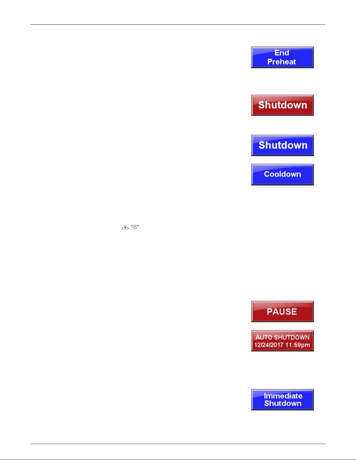
Shutdown – Immediate or Planned
End Preheat - (shown only if in a preheat cycle)
Skips the preheat allowing material to immediately pass down
to the Vacuum Chamber (example: material has already been
heated and dryer has been taking offline briefly and powered
back on).
At any point during the preheat cycle or standard operation
(operation after initial preheat cycle), pressing the red
Shutdown button will bring up the Shutdown Options screen
with the following shutdown options:
Shutdown – Shutdown will continue to run the dryer and
process the material in the Vacuum Chamber and the
Retention Hopper until they are empty. Selecting Planned
Shutdown will display the Cooldown option.
Cooldown (ON/OFF) – When enabled Cooldown will
gradually bring down the temperature of the material in the
heating hopper to the specified temperature (Cooldown
Temp) over the specified time period (Cooldown Time).
To adjust the Cooldown Temperature and Cooldown Time
use the arrow buttons to adjust the setting. Press
ENTER to advance through the digits and to complete the
setting adjustment.
Press the Shutdown button to shutdown.
Pressing the red power button during a Planned Shutdown
will display the Immediate Shutdown Screen allowing
initiation of an immediate shutdown of the dryer.
Maguire Products, Inc.
Pause – Press the Vacuum Chamber will display the Vacuum
Chamber Setup screen. Pause is the red button at the bottom
of the screen. Pauses the vacuum timer indefinitely. To
restart after a pause, press RESUME.
Auto Shutdown – Initiates a shutdown (see above) at
specified date and time. For further explanation on how to set
the Auto Stop date and time see page 27.
Immediate Shutdown – Fast but controlled shutdown of the
heater, blower, the vacuum system and the purge system.
Cancel - Exits the shutdown prompt screen, doing nothing.
26
Rev. March 5, 2018 – VBD-1000 Touchscreen
 Loading...