

Maguire Products SW, SW-4815, SW-4820, SW-8415, SW-8420 Instruction And Operation Manual
...
MAGUIRE PRODUCTS INC.
SW SERIES SWEEPERS
Models:
SW-4815
SW-4820
SW-4825
SW Series Sweeper
Gaylord Sweeper Evacuation System
INSTRUCTION AND OPERATION MANUAL
Original Instructions Manual
Revision Date: February 22, 2019
Copyright Maguire Products, Inc. 2019

S W S E R I E S S W E E P E R
M A G U I R E P R O D U C T S , I N C .
2

S W S E R I E S S W E E P E R
Table of Contents
SW Series Sweeper Basic Operation ____________________________5
M A G U I R E P R O D U C T S , I N C .
Maguire Products Inc.
SW Series Sweeper
Gaylord Sweeper Evacuation System
Models: SW-4815, SW-4820, SW-4825
Sweeper Setup ______________________________________________6
Wiring Diagrams ___________________________________________11
Warranty __________________________________________________14
Technical Support and Contact Information _____________________15
3

S W S E R I E S S W E E P E R
M A G U I R E P R O D U C T S , I N C .
Copyright
2019 Maguire Products Inc.
The information contained within this manual including any translations thereof, is the property of
Maguire Products Inc. and may not be reproduced, or transmitted in any form or by any means
without the express written consent of Maguire Products Inc.
To every person concerned with use and maintenance of the Maguire SW Series Sweeper it is
recommended to read thoroughly these operating instructions. Maguire Products Inc. accepts no
responsibility or liability for damage or malfunction of the equipment arising from non-observance of
these operating instructions.
To avoid errors and to ensure trouble-free operation, it is essential that these operating instructions
are read and understood by all personnel who are to use the equipment.
Should you have problems or difficulties with the equipment, please contact Maguire Products Inc.
or your local Maguire distributor.
These operating instructions only apply to the equipment described within this manual.
Manufacturer’s Contact Information
Maguire Products Inc.
11 Crozerville Road
Aston, PA. 19014
Phone: 610.459.4300
Fax: 610.459.2700
Website: http://www.maguire.com
Email: info@maguire.com
4
S W S E R I E S S W E E P E R
M A G U I R E P R O D U C T S , I N C .
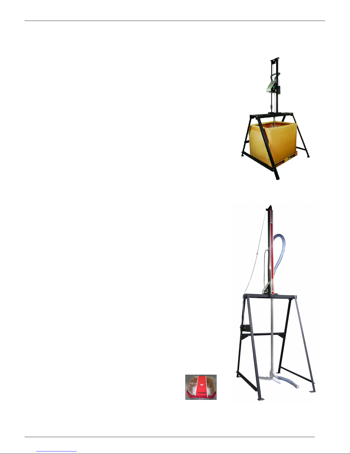
Maguire SW Series Sweeper Basic Operation
The SWEEPER gets its name from the fact that it
continuously "sweeps" the top level of the
contents of the Gaylord to the outer edges. The
material is vacuumed up the rotating vertical pick
up tube assembly, which in turn has a flexible
hose and wand assembly that rotates. As the pick
up tube assembly rotates the material is drawn up
thru the vertical portion, and into the
manufacturing process.
The motor that rotates the pick up tube is only
activated when vacuum is sensed from the users
conveying system. As the unit unloads the material
from the gaylord, the counterbalance system
allows the motor / control assembly to lower and
follow the level of the material. When the sweeper
reaches to the bottom of the gaylord, there will be
a small amount of material remaining, which can
be easily removed with the Gaylord liner and
returned to inventory.
The whole system is very portable and can be
easily transported from one location to another.
Available in six models sizes.
SW-4815 - 48-inch clearance, 1.5" (38mm) hose diameter.
SW-4820 - 48-inch clearance, 2.0" (50mm) hose diameter.
SW-4825 - 48-inch clearance, 2.5" (63mm) hose diameter.
SW-8415 - 84-inch clearance, 1.5" (38mm) hose diameter.
SW-8420 - 84-inch clearance, 2.0" (50mm) hose diameter.
SW-8425 - 84-inch clearance, 2.5" (63mm) hose diameter.
Power Requirements: 120 VAC or 230 VAC, model dependent.
Available optional Sweeper Cover that completely
covers the material in the gaylord. Part number
GLC-4848.
SW- 4815, SW-4820, SW-4825
Overall gaylord clearance up to 48 Inches
SW-8415, SW-8420, SW-8425
Overall gaylord clearance up to 84 inches
5

S W S E R I E S S W E E P E R
M A G U I R E P R O D U C T S , I N C .
SWEEPER SET-UP
Your unit consists of 3 basic separate assemblies:
1. The stand assembly
2. The vertical frame assembly
3. The pick-up tube assembly
FIRST STEP - ASSEMBLE THE STAND
Refer to drawings for identification and location of parts & hardware.
The rear stop bar can be placed in an upper or lower position to suit the
dimensions of the material Gaylord.
6

S W S E R I E S S W E E P E R
M A G U I R E P R O D U C T S , I N C .
7

S W S E R I E S S W E E P E R
M A G U I R E P R O D U C T S , I N C .
8

S W S E R I E S S W E E P E R
M A G U I R E P R O D U C T S , I N C .
SECOND STEP - BOLT THE VERTICAL ASSEMBLY TO STAND
1. Refer to enclosed drawing for
identification and location of parts
& hardware. Please note that the
front or sloped side of the sweeper
assembly should face the leg that
has the chain catch plate. Ensure
to center the vertical assembly on
the frame of the stand.
THIRD STEP – ATTACH THE PICK-UP TUBE ASSEMBLY
2. First, remove the aluminum end guard by
removing the two self-tapping screws (see
photo). Allow the clear Lexan® chain guard
to hang down. It is not necessary to remove
the Lexan® chain guard.
3. Remove the four (4) locknuts and washers
that are attached to the sprocket hub
assembly.
4. Raise the motor control assembly to allow for
clearance to insert the pick up tube assembly
into the pulley hub assembly. Slowly, push
upward until the flange is seated firmly
against the sprocket hub assembly.
5. Reinstall and tighten the four ¼-20 locknuts
and washers. Please refer to enclosed
assembly instructions for details.
(2) Remove end guard
(5) Reinstall washers, locknuts (6) Reinstall end guard
(4) Insert pickup tube
6. Reinstall the aluminum end guard and tighten screws. Note: Be sure there is clearance
between Gaylord frame top member.
Drive Chain Adjustment
If the chain needs adjustment, remove the clear Lexan® portion of the chain guard.
Loosen the (4) four machine screws. Apply pressure to the rear of the motor (This will
apply tension to the chain and sprocket). Do not apply too much force to the chain tension.
Then tighten the (4) screws at the bottom of the motor / bracket assembly. Re-install the
clear Lexan® belt guard.
9

S W S E R I E S S W E E P E R
Counter balance weights
The assembly has a counterbalance system that is set at the factory to favor
a downward brush direction to sweep the material efficiently. We have included
additional weights, with your unit. Additional weights may be needed if the brush /
wand assembly requires less downward force such as preventing the brush / wand
from burying itself into the process material.
Controls
The main power switch is located at the base of the vertical frame member. When the
power is turned “ON” the green indicator light will glow indicating power is on. The
yellow indicator light directly below the green indicator light will indicate when the
vacuum is present. The JOG button rotates the sweeper mechanism into a
convenient position to allow for material gaylord insertion and removal. When the
JOG button is depressed this yellow indicator light will glow.
M A G U I R E P R O D U C T S , I N C .
Fuse Location
The 2 amp control circuit fuse is located under the aluminum motor cover.
Use 2 AMP Slow Blow Fuse 115 VAC and 230 VAC
Vacuum Switch
The vacuum switch is also located under the aluminum motor cover. This switch
activates the motor control circuit as soon as it “sees” vacuum in the material line. It
is factory preset.
10

S W S E R I E S S W E E P E R
Wiring Diagram
M A G U I R E P R O D U C T S , I N C .
11

S W S E R I E S S W E E P E R
M A G U I R E P R O D U C T S , I N C .
12

S W S E R I E S S W E E P E R
M A G U I R E P R O D U C T S , I N C .
13

S W S E R I E S S W E E P E R
M A G U I R E P R O D U C T S , I N C .
WARRANTY - Exclusive 5-Year
MAGUIRE PRODUCTS offers one of the MOST
COMPREHENSIVE WARRANTIES in the plastics equipment
industry. We warrant each SW Series Sweeper manufactured
by us to be free from defects in material and workmanship
under normal use and service; our obligation under this
warranty being limited to making good at our factory any SW
Series Sweeper which shall within FIVE (5) YEARS after
delivery to the original purchaser be returned intact to us,
transportation charges PREPAID, and which our examination
shall disclose to our satisfaction to have been thus defective;
this warranty being expressly in lieu of all other warranties
expressed or implied and of all other obligations or liabilities on our part, and MAGUIRE
PRODUCTS neither assumes nor authorizes any other persons to assume for it any other liability
in connection with the sale of its products.
This warranty shall not apply to any SW Series Sweeper which shall have been repaired or
altered outside MAGUIRE PRODUCTS factory, unless such repair or alteration was, in our
judgment, not responsible for the failure; nor which has been subject to misuse, negligence or
accident, incorrect wiring by others, or installation or use not in accord with instructions furnished
by Maguire Products.
Our liability under this warranty will extend only to Feeders that are returned to our factory in
Aston, Pennsylvania PREPAID.
It should be noted, however, that we strive to satisfy our customers in whatever manner is
deemed most expedient to overcome any problems they may have in connection with our
equipment.
14

S W S E R I E S S W E E P E R
Technical Support and Contact Information
Maguire Products Inc.
11 Crozerville Road
Aston, PA 19014
Tel: 610.459.4300
Fax: 610.459.2700
Email: info@maguire.com
Web: www.maguire.com
Maguire Europe
Tame Park
Tamworth
Staffordshire
B775DY
UK
Tel: + 44 1827 265 850
Fax: + 44 1827 265 855
Email: info@maguire-europe.com
M A G U I R E P R O D U C T S , I N C .
Maguire Products Asia PTE LTD
Main Office
No. 15 Changi North Street 1
#01-15, I-Lofts
Singapore 498765
Tel: 65 6848-7117
Fax: 65 6542-8577
E-mail: magasia@maguire-products.com.sg
Maguire Italy
Via Zancanaro 40
35020 Vigorovea (PD)
Tel: +39 049 970 54 29
Fax: +39 049 971 18 38
Email: info@maguire-italia.it
15
 Loading...