

Maguire Products GRAVIMETRIC AUGER FEEDER MGF-ST Instruction Manual

MAGUIRE PRODUCTS INC.
GRAVIMETRIC AUGER FEEDER
MAGUIRE
GRAVIMETRIC AUGER FEEDER
Original Instructions Manual
Revision Date: December 4, 2018
Model MGF-ST
Touch Screen Controller
INSTRUCTION MANUAL
Copyright Maguire Products, Inc. 2018
G R A V I M E T R I C A U G E R F E E D E R
Use this space to record information about your Maguire Machines:
M A G U I R E P R O D U C T S , I N C .
Serial Number Date of Purchase Model Number ID IP Address
Notes:
2

G R A V I M E T R I C A U G E R F E E D E R
M A G U I R E P R O D U C T S , I N C .
Maguire MGF-ST
This document is the Original Instructions manual of the Maguire MGF-ST with the Touchscreen
controller.
Copyright 2018 Maguire Products Inc.
The information contained within this manual including any translations thereof, is the property of
Maguire Products Inc. and may not be reproduced, or transmitted in any form or by any means
without the express written consent of Maguire Products Inc.
To every person concerned with use and maintenance of the Maguire MGF-ST it is recommended
to read thoroughly these operating instructions. Maguire Products Inc. accepts no responsibility or
liability for damage or malfunction of the equipment arising from non-observance of these operating
instructions.
To avoid errors and to ensure trouble-free operation, it is essential that these operating instructions
are read and understood by all personnel who are to use the equipment.
Should you have problems or difficulties with the equipment, please contact Maguire Products Inc.
or your local Maguire distributor.
Manufacturer’s Contact Information
Maguire Products Inc.
11 Crozerville Road
Aston, PA. 19014
Phone: 610.459.4300
Fax: 610.459.2700
Website: http://www.maguire.com
Email: info@maguire.com
3

G R A V I M E T R I C A U G E R F E E D E R
Table of Contents
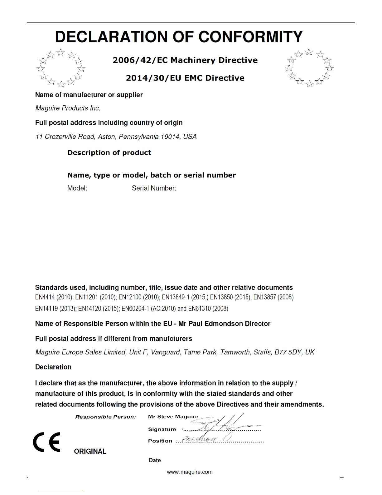
EC Declaration of Conformity ____________________________________________ 5
Safety Notifications and Safety Hazards ___________________________________ 6
Features _____________________________________________________________ 7
Assembly and Installation Instructions ___________________________________ 8
Description of Controls ________________________________________________ 9
Touchscreen Overview _______________________________________________ 10
Software Setup (First Time Setup) ______________________________________ 11
Startup Instructions __________________________________________________ 13
Normal Operation ____________________________________________________ 14
Alarms and Troubleshooting ___________________________________________ 15
Troubleshooting Loss of Color _________________________________________ 17
M A G U I R E P R O D U C T S , I N C .
MGF Menu Navigation and Overview ____________________________________ 18
Troubleshooting Controller Problems ___________________________________ 18
Settings Menu Explained ______________________________________________ 18
Password Management _______________________________________________ 20
Weight Units ________________________________________________________ 20
Volumetric Mode _____________________________________________________ 21
Print Center _________________________________________________________ 22
Parameters _________________________________________________________ 28
Updating the MGF Firmware ___________________________________________ 32
Rate Adjust Reset ____________________________________________________ 33
View / Reset Totals ___________________________________________________ 33
MGF Defaults _______________________________________________________ 33
Optional Loader Installation ___________________________________________ 34
AGL Loader Diagram _________________________________________________ 35
MGF Wiring Diagram _________________________________________________ 39
Parts diagram / Dimensions ___________________________________________ 42
Principle of Feeder Operation __________________________________________ 45
Principle of Controller Operation _______________________________________ 45
Warranty ___________________________________________________________ 46
Technical Support and Contact Information ______________________________ 47
4
G R A V I M E T R I C A U G E R F E E D E R
M A G U I R E P R O D U C T S , I N C .
5
G R A V I M E T R I C A U G E R F E E D E R
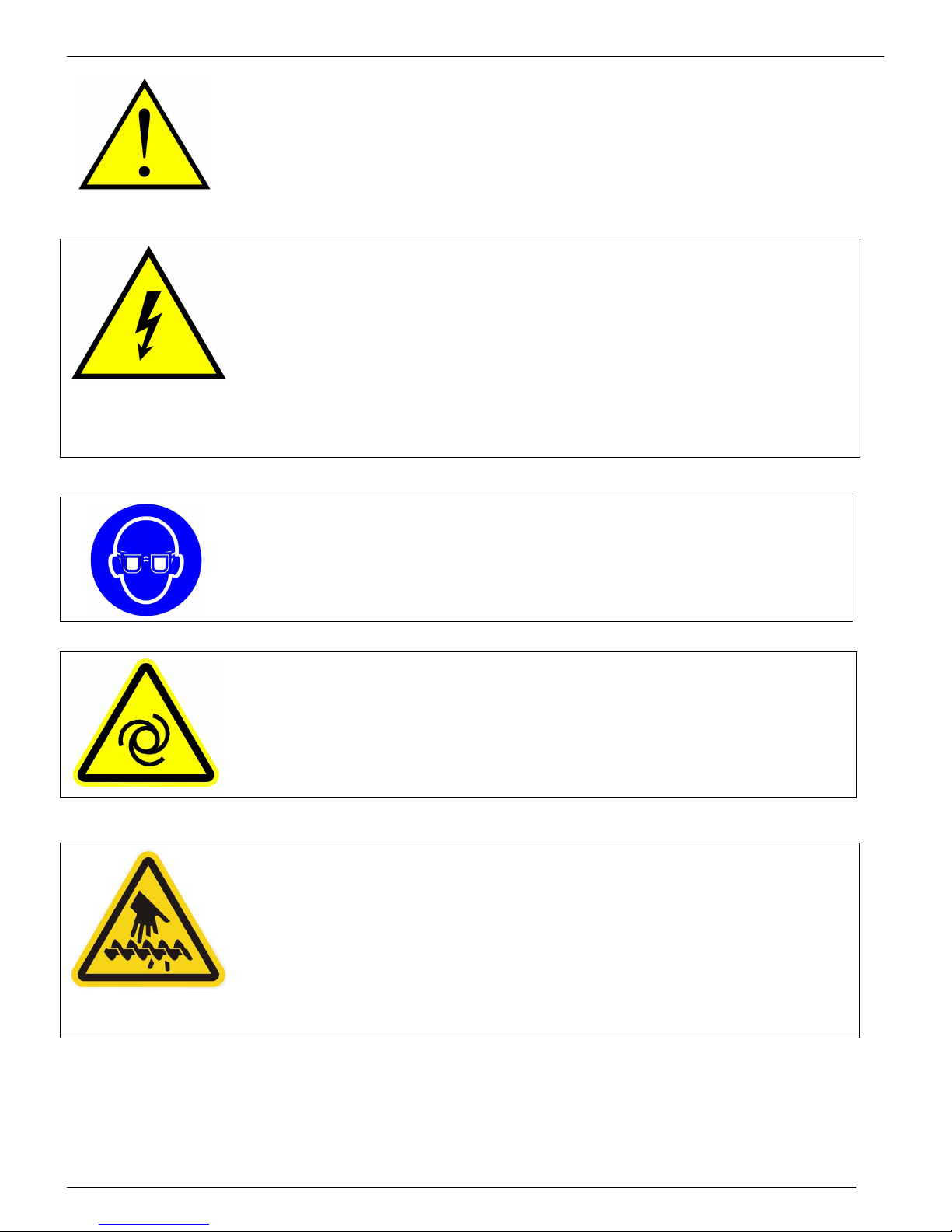
Safety Notifications
HAZARD - ELECTRICAL
Only qualified electrical technicians should make
electrical connections. Disconnect and lockout power
supply before servicing Blender.
Disconnect electric before opening or servicing. Use
Power Lockout Tagout.
M A G U I R E P R O D U C T S , I N C .
CAUTION - Always wear safety glasses when using this
equipment.
HAZARD - AUTOMATIC STARTUP
WARNING - Feeder may start automatically without warning.
HAZARD - ROTATING AUGER
The auger is driven with substantial Torque.
Never place your hand in the MGF while the auger is rotating.
SERIOUS INJURY WILL RESULT
ALWAYS keep fingers clear of rotating shaft and auger.
NEVER use your fingers to clear an obstruction.
NEVER touch a rotating shaft or auger.
6
G R A V I M E T R I C A U G E R F E E D E R
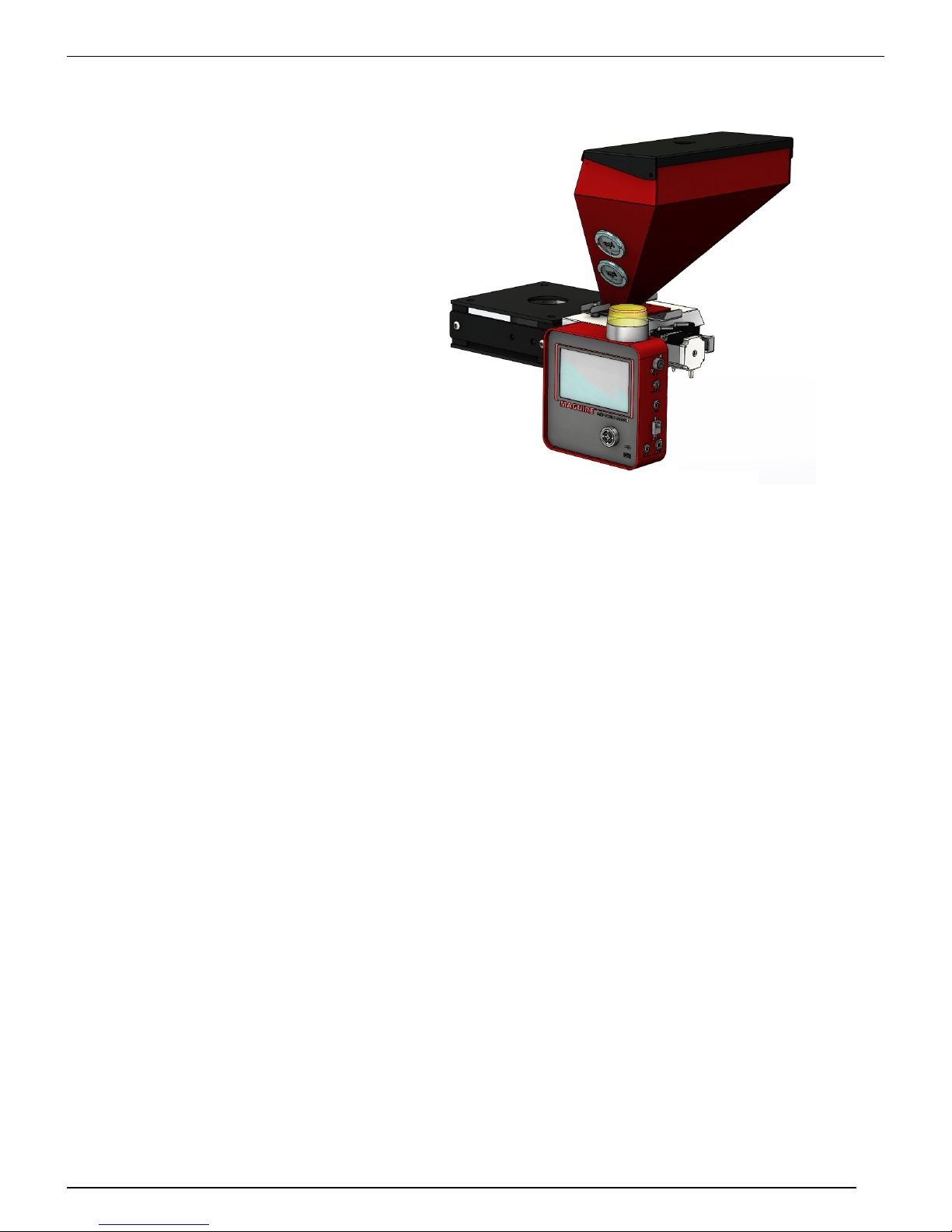
Maguire MGF-ST Features
MGF-ST
Gravimetric
Feeder
Throughput capacity:
Injection molding –
Up to 40.0 lb/hr
(18 kg/hr)
Extrusion –
Up to 120.0 lb/hr
(55 kg/hr)
Full function gravimetric
feeder for the price of a
volumetric model.
M A G U I R E P R O D U C T S , I N C .
Eliminate Waste of Colorants and Additives
This compact loss-in-weight additive feeder precisely measures the amount of additive
that is fed directly into the machine throat to eliminate costly waste.
Standard features:
3 Standard Modes of Operation
Cyclical, Continuous and Extrusion Following
Modes. Rate (volumetric) also available.
Reduces Input Error
The easiest setup procedure in the industry: enter
let-down ratio and either shot weight or lb/hr
output and press start. Feeder automatically
adjusts to screw recovery time and extruder
output.
Fine Metering Resolution
100 rpm Stepper Motor advances at 200
increments per revolution. In combination with
digital control, the 200-step rotation achieves fine
metering resolution of ± 0.2%.
Automatic Re-calibration Ensures
Continuous Accuracy
Automatic adjustments guarantee that feed rate is
held to within ± 0.2% of desired let-down ratio.
Dual Load Cells
Balanced load readings improve accuracy.
Torque-limiting Drive Coupling
Protects drive motor in case of jammed auger.
Easy-to-Use Microprocessor Controller Saves
Time
User-friendly controller has intuitive setup
procedure.
USB Port
Allows data download, data printout and
software update capability.
Detailed Material Usage Documentation
Microprocessor control allows data collection via
G2 networking software, or MLAN protocol via
Ethernet.
Eliminates Downtime Associated with Color
Change
Feeder automatically re-calibrates to new color,
so no additional setup required. Spare hoppers
available for faster color changes.
Exclusive 5-Year Warranty
7
G R A V I M E T R I C A U G E R F E E D E R
M A G U I R E P R O D U C T S , I N C .
ASSEMBLY AND INSTALLATION INSTRUCTIONS
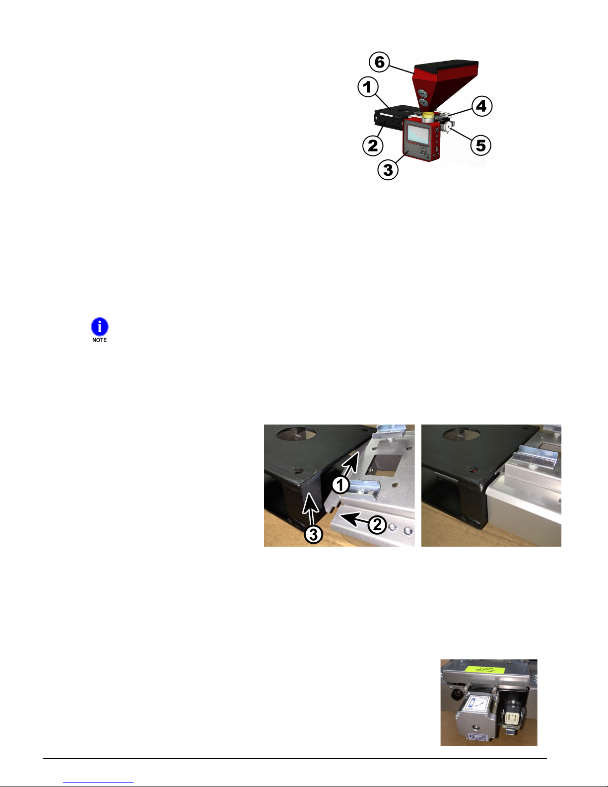
The MGF consists of these assemblies:
1. The Adaptor Frame Assembly
2. The Bar Assembly (for the Controller).
3. The Controller
4. The Load Cell Assembly
5. The Auger Tube Assembly
6. The Hopper Assembly
MOUNT THE ADAPTOR FRAME
1. The ADAPTOR frame mounts directly to the throat under your current natural material hopper.
For proper ORIENTATION, consider the following:
• Orient the Auger Tube Assembly at 90° to the machine barrel.
• Clearance and ease of access for removing the hopper.
• Easy viewing and access to the controller.
• The feeder will hang from the side of the adapter that has the opening into the flow chamber.
2. Locate and drill the proper bolt patterns (top and bottom of the adapter frame). This frame will be bolted
directly to the feed throat of your process machine and the natural material hopper will be bolted on top.
The TOP plate has the ROUND hole.
The BOTTOM plate has the SQUARE hole.
MOUNT THE CONTROLLER
3. The CONTROLLER will be mounted to a bar that bolts on the left side of the adaptor frame. You may also
mount the controller in a remote location and use optional extension cords to connect the motor and load cell.
Be sure that the mounting screws are tight.
HANG THE LOAD CELL ASSEMBLY
4. Hang the Load Cell Assembly from the
side of the frame with the opening into
the chamber. (See photo) Tilt unit. (1)
Slip upper ear behind the corner post.
(2) Slip the lower ear behind the other
corner post. (3) Raise the lower ear up
and rest the load cell assembly into
frame as shown.
INSTALL AUGER TUBE ASSEMBLY
5. Insert the Auger Tube Assembly into Load Cell Assembly and hang onto the two bolt heads.
INSTALL HOPPER ASSEMBLY
6. Place the hopper assembly on the load cell assembly and secure with the hold downs.
PLUG IN ALL CORDS
7. Plug the motor and load cell cables into the Load Cell Assembly.
8. Plug the black power cable into a standard 120-volt (EURO, 230 VAC) outlet.
8
G R A V I M E T R I C A U G E R F E E D E R
CONNECT SIGNAL CABLE
9. Standard equipped for contact closure applications only, your controller will be equipped with the supplied
cable lead and 5-pin connector. You will also have a 20’ length of cable with a mating 5-pin connector. This
cable will connect to the MGF controller using the connector, and the open end will be wired to your
equipment. The open ends leads should be wired to the screw signal normally open contact closure. When
the screw is retracting contacts will close and then open at the end of the retract. The time closed is used by
the MGF to adjust output. This 5-pin connector is also used with an extrusion following 0-10 volt signal.
See the MGF wiring diagram on page 39.
M A G U I R E P R O D U C T S , I N C .
10. If optionally ordered with 24 to 120 VDC or VAC plug the "SIGNAL" (gray) cord will be plugged into outlet that
is energized only when the screw is turning. Signal voltage can be from 24 to 120 VDC or VAC. The screw
signal on-time can not be less then 1 second. INJECTION time or CLAMP CLOSE time are options.
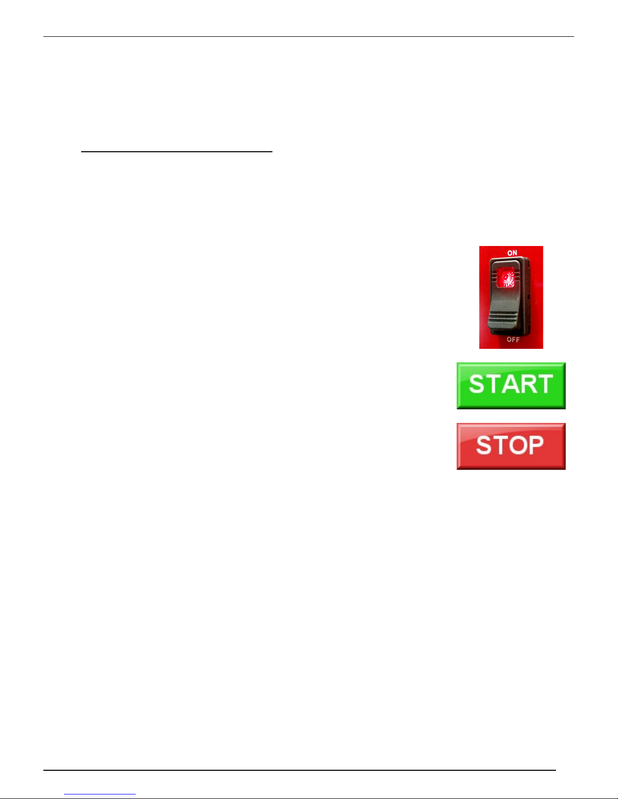
Description of Controls
1. POWER ON / OFF SWITCH - Turns power on or off. Switch light
is illuminated when MGF is powered ON.
2. START / STOP on-screen button - This on-screen button
provides a run signal to the circuit board. For the MGF feeder to
run, a screw turning signal MUST be present, providing power to
the screw signal cord, AND the RUN switch must be in the RUN
position. The only exception is when the PRIME feature is
selected. This will operate the auger without any Run signal.
9
G R A V I M E T R I C A U G E R F E E D E R
Prime Auger
Run Loader
Title Bar
Touchscreen Overview
M A G U I R E P R O D U C T S , I N C .
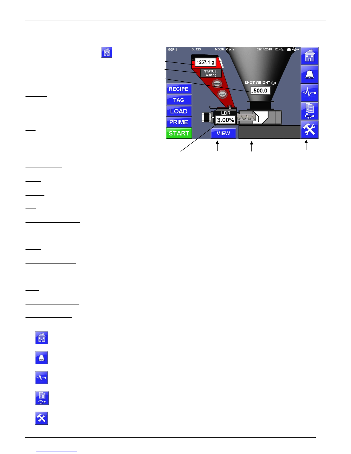
Home Screen
The Home Screen contains
several fields and buttons:
Title Bar - Located across the top of the
screen, the title bar displays Model, ID,
current operating mode, date and time,
Ethernet and USB status.
Info - The i (info) button displays
information about the MGF including
firmware and serial number.
Actual Weight – The actual weight of material currently in the hopper.
Mode – Displays current configuration. Cycle, Continuous or Extrusion Following mode.
Recipe – Screen to set, save and load preconfigured MGF settings.
Tag – Screen to set material tag information. Operator, Recipe and Work Order tags. Used in communications.
Shot Weight or Rate – Displayed setting based on selected Mode. Metering Rate or Shot Weight. See page 11.
Load – On/Off button (if enabled) activates the loader. See page 27.
Prime – Primes and calibrates the MGF - See page 14.
Start / Stop Button – Main Start / Stop Control Button of the MGF.
Let Down Ratio (LDR) – Let Down Ratio, Percent. See page 11.
View – Screen to view, clear or save: MGF ID, date/time, totals, cycles, work order, recipe, operator. See page 33
Injection / Recovery –Cycle Mode only. Displays the state of the cycle, Injection or Recovery.
Navigation Menu - Located along the right side of the screen, these buttons allow quick navigation to frequently
used and top-level screens. The middle three buttons are soft buttons that can be changed or removed.
Home Screen
Pressing the Home Screen button from any other screen will return the operator to the main
Home Screen.
Actual Weight
MGF Status
Shot Weight
or Rate
Start / Stop
Let Down Ratio
View Totals Injection/Recovery Navigation Menu
Alarm and Event
Live Diagnostics
Print Center
Setup
Alarm and Event Log displays a history of alarms and other events with a date and time
stamps and description.
Live Diagnostics displays a cycle summary of detailed diagnostics information scrollable
back through a history of cycles printable to USB.
A menu screen of print related options including Totals, Parameters, Alarm History, Events,
Cycle History, Diagnostics.
Password protected area to access the MGF settings. See page 18.
10
G R A V I M E T R I C A U G E R F E E D E R
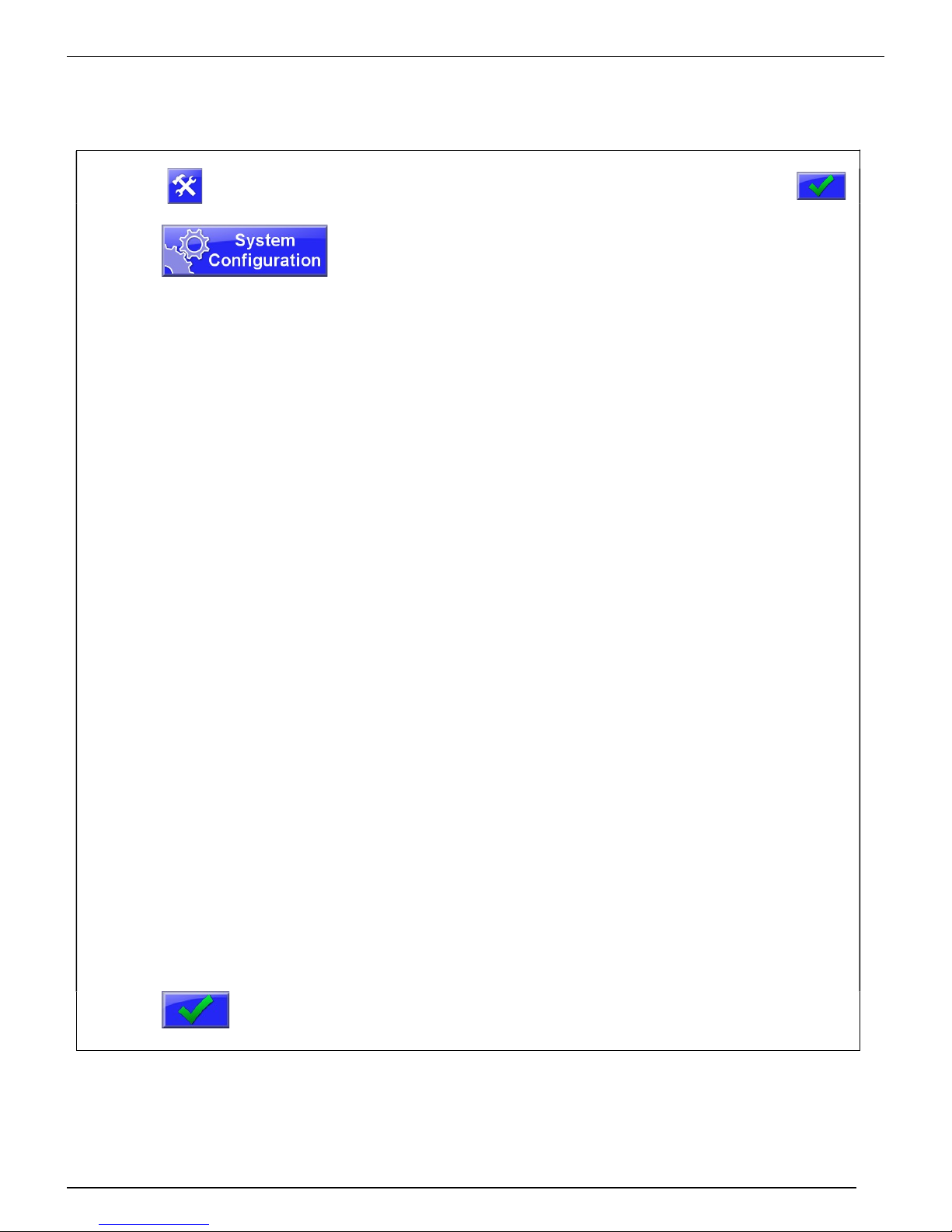
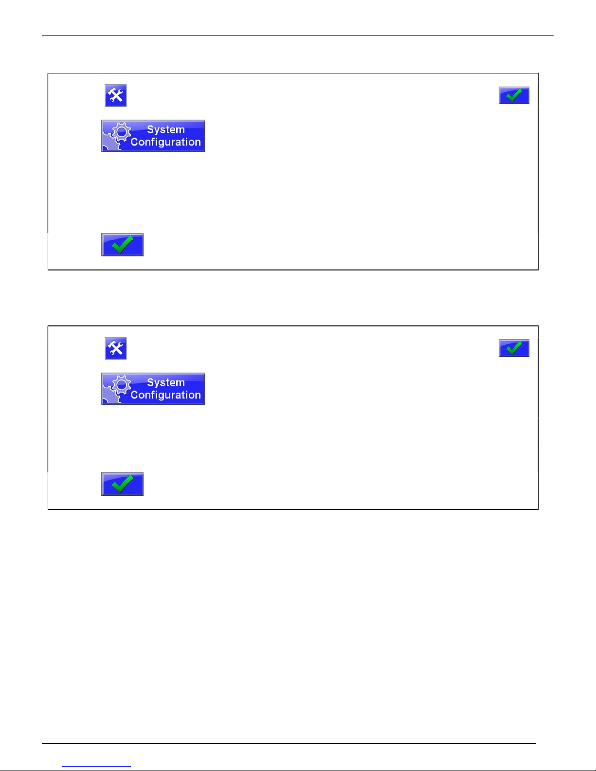
SOFTWARE SETUP - FIRST TIME ONLY
Select Mode of Operation – CYCLE, CONTINUOUS, EXTR FLLW
Press
Display will prompt for a password. (default: 22222)
M A G U I R E P R O D U C T S , I N C .
Then press:
Press
Press
Press
Display will show the System Configuration categories.
Mode of Operation Select the Mode of Operation:
Cycle, Continuous or Extrusion Following
Select CYCLE...
for injection molding, where the MGF auger turns on and
off with each cycle. In this mode the first step is to enter
the SHOT WEIGHT of the part on the main screen. Next
set the LDR (Let Down Ratio) on the main screen. In
CYCLE mode your MGF will dispense the calculated rate
(shot weight x LDR) during the length of screw recover
time.
Select CONTINUOUS...
for extrusion, where the MGF auger runs continuously. In
this mode the first step is enter LBS (or KILOS) / HOUR
of the extruder on the main screen. Next set the LDR
(Let Down Ratio) on the main screen. In CONTINUOUS
mode your MGF will run continuously at the calculated
rate (lbs/hr x LDR). Auger speed will adjust automatically
to maintain dispense rate.
Select Extrusion Following
for extrusion, where the MGF auger runs continuously by
following the 0-10 volt reference voltage of the extruder
screw. In this mode the first step is to set the XMO
parameter. Setting XMO will automatically calculate
extruder throughput on the main screen based on a 0-10
volt reference. See page 28 for XMO. Next set the LDR
(Let Down Ratio) on the main screen. In Extrusion
Following mode your MGF will run continuously at the
calculated rate (lbs/hr x LDR). Auger speed will adjust
automatically to maintain dispense rate.
To save the Changes.
11
G R A V I M E T R I C A U G E R F E E D E R
Select Units – Pounds, Grams or Kilograms
Press
Display will prompt for a password. (default: 22222)
M A G U I R E P R O D U C T S , I N C .
Then press:
Press
Press
Press
Preferences
Weight Units
Press
Set Date and Time
Press
Press
Press
Press
Preferences
Date and Time
Press
Display will show the System Configuration categories.
Display will show the System Preferences categories.
Select the Weight Units:
Pounds, Grams or Kilograms.
To save the Changes.
Display will prompt for a password. (default: 22222)
Display will show the System Configuration categories.
Display will show the System Preferences categories.
Using the keypad, set the date, time and date format.
To save the Changes.
Then press:
12
G R A V I M E T R I C A U G E R F E E D E R
M A G U I R E P R O D U C T S , I N C .
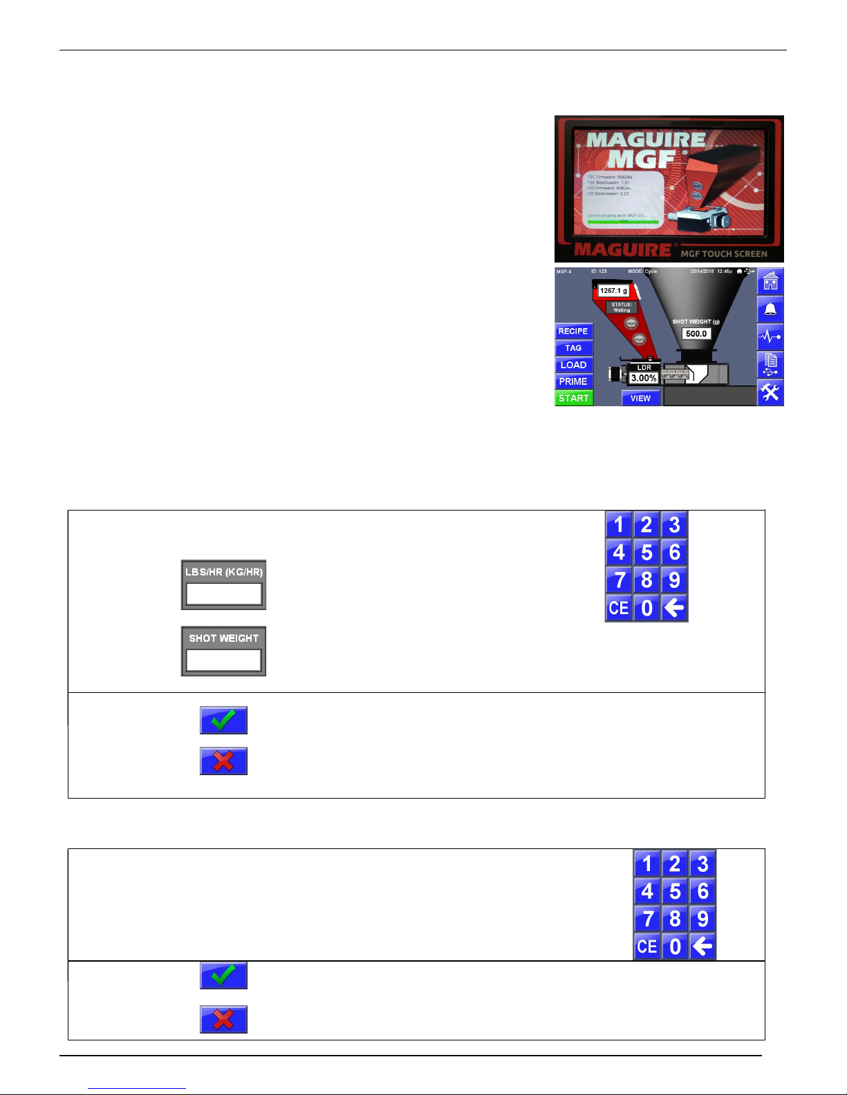
Start Up Procedure
1. Turn POWER ON:
The opening screen displays for 5 seconds and shows
your current firmware and bootloaders software versions
for the touchscreen controller and I/O, in the information
window.
The display then shows the Main Home Screen of the
MGF. Depending on your Mode of Operation, the Main
screen will either display Shot Weight (grams) for Cycle
Mode or Pounds or Kilograms per hour for Continuous
Mode.
Adjustments
Depending on your selected Mode, the display will show SHOT/WT or LBS/HR (KG/HR).
To adjust this value, follow these instructions:
Press field LBS/HR (KG/HR)
or
Display will show the Per Hour
Rate or Show Weight Screen
showing the current setting. Use
the keypad to set a new rate or
shot weight.
Press
Press
LDR – Let Down Ratio - To adjust this value, follow these instructions:
Press field
(Let Down Ratio)
Press
Press
LDR
Saves and loads new setting and return to Home.
Cancels the new setting, revert to original settings and
returns to the Home Screen.
Display will show the Let Down Ratio
screen showing the current LDR setting.
Use the keypad to set a new LDR. The
decimal is hard coded to 100
ths
of a %.
Saves and loads new LDR setting, return to Home.
Cancels the new setting, revert to original settings and
returns to the Home Screen.
13
G R A V I M E T R I C A U G E R F E E D E R
M A G U I R E P R O D U C T S , I N C .
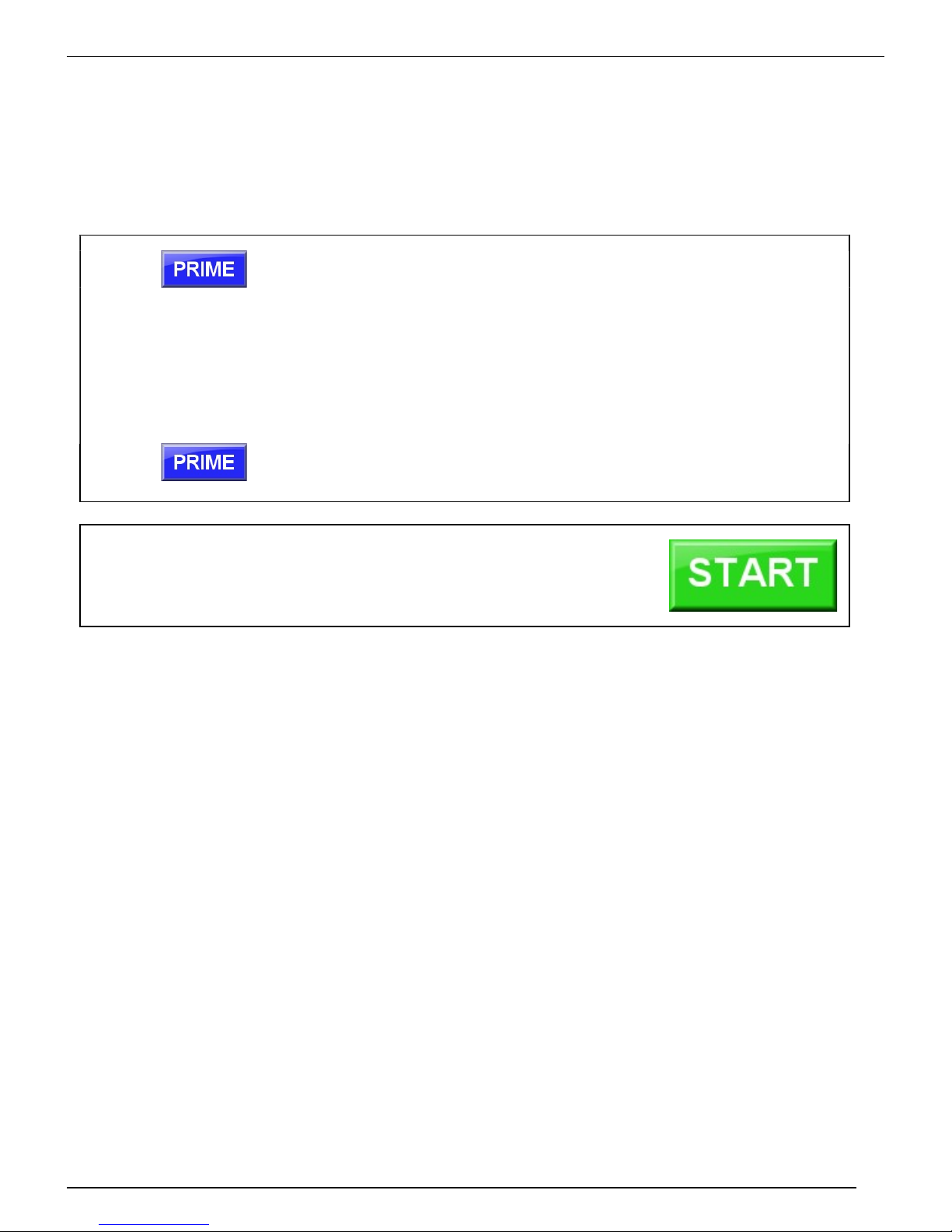
Prime the MGF Auger / Calibrate
It may be necessary to prime the auger prior to running. Prime will allow the MGF to run without a
signal from the process machine. Run time is automatically limited to ONE minute. After one
minute the display will read “PRIME TIMED OUT”. During the Prime, the MGF automatically
calibrates the flow rate of the material. To Prime, follow these instructions:
Press
Display will show animated movement on the auger. A 60-second
counter will begin to count down. During this time the MGF will selfcalibrate and display CALIBRATED indicating that it has learned the
flow rate of your specific material and has adjusted the motor factor
accordingly. After CALIBRATED has displayed, the prime function can
be ended by pressing the BACK button, otherwise prime will continue
to run for 60 seconds, then timeout and alarm, displaying “PRIME
TIMED OUT”.
Press
To stop the prime function.
When the MGF settings are adjusted and the MGF is primed
with material, it is ready for operation.
Press the START button run the MGF.
What happens during NORMAL OPERATION
The software uses the information you have entered, lbs/hr (or shot wt) and Let Down Ratio, plus
the motor factor, to determine a correct percentage off-time between steps for the motor to control
speed.
Two 10K load cells detect the loss of weight after each dispense. Based on this feedback,
adjustments are made to the percentage off-time to maintain the correct metering rate.
In the CONTINUOUS mode the percentage off-time, (motor speed) is adjusted to hold the correct
loss in weight of the hopper.
In the CYCLE mode the speed is adjusted to meter the correct amount over the full screw signal
cycle time. A change in process screw signal time will result in an adjustment to motor speed.
Speed adjustment is based on the previous screw return time. If screw return time is SHORTER
then the PREVIOUS time, the auger motor will continue past the end of the run signal for 1
additional second. It will run faster on the next dispense to end in time.
14
G R A V I M E T R I C A U G E R F E E D E R
Alarms and Troubleshooting
NO METERING - ALARM CODE:48
This alarm indicates that no loss in weight has been detected during the last
several cycles. After clearing the alarm, metering will continue, however the
alarm will not re appear until after you have remedied the problem.
The following conditions are required to generate the NO METERING ALARM
a. Before this alarm is checked, the system needed to have been running for at least 24
seconds.
b. If the MGF is in continuous or extrusion follow mode, the target rate needs to be more
than 7.5 g/min.
c. If the MGF is in cycle mode, the target rate needs to be more than 2 grams / cycle.
If the above conditions (a and (b or c)) are met, then the MGF will compare the current bin weight
with a captured value from 24 seconds ago.
d. If the MGF is in continuous or extrusion following mode, the difference between the two
weights need to greater than 10 times the target rate.
e. If the MGF is in cycle mode, the difference between the two weights needs to be greater
than 5 times the target rate.
If the above condition (d or e) fails, then a counter is incremented
If the above condition (d or e) passes, then the counter is reset to 0.
If the counter gets incremented past 3, then the NO METERING alarm is triggered.
In cycle mode, the NO METERING alarm is checked only at the start of every cycle.
In continuous or extrusion following mode, the NO METERING alarm is checked every RTU
update.
M A G U I R E P R O D U C T S , I N C .
LOADING TOO SLOWLY - ALARM CODE:49
If the loading feature is enabled and it takes more than LAT (Loader Alarm Time)
seconds to fill the bin to LHF (Loader High Level) grams then this alarm is
triggered.
PRIME ALARM - ALARM CODE:50
This alarm indicates that the 60-second Prime cycle time has ended. The Prime
function is used to prime the feeder and is accessible from the main menu. It
operates by running the feeder auger for one minute to prime the feeder then
alarms to alert the operator that the prime cycle has ended.
LOW WEIGHT ALARM - ALARM CODE:51
If the bin weight falls below the LWA (Low Weight Alarm) setting (Default 400g)
then this alarm will be triggered. If the bin weight rises above the LWA
parameter, then the alarm will shut off.
15
 Loading...