

MAGUIRE PRS-20 Maintenance Manual

MAGUIRE PRODUCTS INC.
Purging Recovery System
®
MAGUIRE
Purging Recovery System
INSTALLATION • OPERATION • MAINTENANCE
Copyright © Maguire Products, Inc. 2012

Maguire Purging Recovery System
Maguire Products, Inc.
2
Edition: June 20, 2012 – PRS-20

Maguire Purging Recovery System
Maguire Products, Inc.
Maguire Purging Recovery System
Copyright
© 2012 Maguire Products Inc.
The information contained within this manual including any translations thereof, is the property of
Maguire Products Inc. and may not be reproduced, or transmitted in any form or by any means
without the express written consent of Maguire Products Inc.
To every person concerned with use and maintenance of the Maguire Purging Recovery System
it is recommended to read thoroughly these operating instructions. Maguire Products Inc.
accepts no responsibility or liability for damage or malfunction of the equipment arising from nonobservance of these operating instructions.
To avoid errors and to ensure trouble-free operation, it is essential that these operating
instructions are read and understood by all personnel who are to use the equipment.
Should you have problems or difficulties with the equipment, please contact Maguire Products
Inc. or your local Maguire distributor.
These operating instructions only apply to the equipment described within this manual.
Manufacturer’s Contact Information
Maguire Products Inc.
11 Crozerville Road
Aston, PA. 19014
Phone: 610.459.4300
Fax: 610.459.2700
Website: http://www.maguire.com
Email: info@maguire.com
Edition: June 20, 2012 – PRS-20
3

Maguire Purging Recovery System
Accuracy of this Manual
We make every effort to keep this manual as correct and current as possible.
However, technology and product changes may occur more rapidly then the
reprinting of this manual. Generally, modifications made to the Maguire Purging
Recovery System design or to the operation of the software are may not reflected
in the manual for several months. The date at the footer of this manual will
indicate approximately how current this manual is. Likewise, your Maguire
Purging Recovery System may have been produced at an earlier time and the
information in this manual may not accurately describe your Maguire Purging
Recovery System since this manual is written for the current line of Maguire
Purging Recovery System in production (as of the date in the footer). We always
reserve the right to make these changes without notice, and we do not guarantee
the manual to be entirely accurate. If you question any information in this manual,
or find errors, please let us know so that we may make the required corrections or
provide you with accurate information. Additionally we will gladly provide you with
an updated copy of any manuals you need at any time. We welcome comments
and suggestions on ways we can improve this manual.
For additional information, or to download the latest copy of this manual or any
other Maguire manual, please visit our website or contact us directly.
On the Web at: www.Maguire.com
Maguire Products Inc.
Main Headquarters
11 Crozerville Road
Aston, PA 19014
Tel: 610.459.4300
Fax: 610.459.2700
Email:
info@maguire.com
Maguire Products, Inc.
Maguire Europe
Tame Park
Tamworth
Staffordshire
B775DY
UK
Tel: + 44 1827 265 850
Fax: + 44 1827 265 855
Email:
info@maguire-europe.com
Maguire Products Asia PTE LTD
45 Kallang Pudding Road
#01-02 Alpha Building
Singapore 349317
Tel: +65 6848 7117
Fax: +65 6744 3370
Email:
magasia@maguire-products.com.sg
Please e-mail comments and suggestions to: support@maguire.com
Maguire Italy
Via Zancanaro 40
35020 Vigorovea (PD)
Tel: +39 049 970 54 29
Fax: +39 049 971 18 38
Email:
info@maguire-italia.it
4
Edition: June 20, 2012 – PRS-20

Maguire Purging Recovery System
Table of Contents
PART 1 GETTING STARTED, READ THIS PAGE
1.1 5 Year Warranty and Disclaimers
1.2 SAFETY Warnings
1.3 Purging Recovery System Terminology
1.4 Concept and Principle of Operation
PART 2 INSTALLATION
2.1 Transport and Setup 13
2.2 Purging Recovery System Installation / Wiring
2.3 Final Checks Before Operation
PART 3 OPERATION
3.1 Standard Operation 17
3.2 Starting / Stopping the PRS-20 19
PART 4 MAINTENANCE AND SERVICE
4.1 General Maintenance 20
4.2 Preventative Maintenance Checklist
4.3 Installing New Shredder Rotor Knives
4.4 Adjustment of Lower Granulator Knife Gaps
4.5 Clearing a Jam 26
4.6 Drain and purge Air Filter / Regulator
4.7 Adjustments
4.8 Cleaning the PRS-20 28
PART 5 TROUBLESHOOTING
5.1 Troubleshooting - Symptoms/Cause
5.2 Clearing a Material Jam due to Plastic Melt
5.3 Cutting Chamber Hardware Diagram
5.4 PRS-20 Wiring Diagrams
PART 6 General Information 45
Our Design Philosophy
Warranty
Technical Support / Contact Information
Maguire Products, Inc.
7
8
9
10
12
13
14
16
17
20
21
22
24
27
27
30
30
32
34
36
45
46
47
Edition: June 20, 2012 – PRS-20
5

Maguire Purging Recovery System
Maguire Products, Inc.
6
Edition: June 20, 2012 – PRS-20

Maguire Purging Recovery System
1 - Getting Started – READ THIS PAGE
PLEASE READ THIS PAGE
You don't have to read the entire manual....
BUT...
PLEASE READ THE NEXT TEN PAGES.
It will take about 10 minutes.
THESE PAGES COVER:
Maguire Products, Inc.
Warranty and Disclaimers: What we Warranty and
what we cannot promise.
SAFETY Warnings: Safety warnings.
INSTALLATION: Assembly and setup.
OPERATION: What buttons to push.
MAGUIRE Shuttle Granulators are protected by U.S. patent 6,405,949.
Other U.S. and International patents are pending.
GETTING STARTED:
PROCEED TO: WARRANTY AND DISCLAIMERS NEXT PAGE
Edition: June 20, 2012 – PRS-20
7

Maguire Purging Recovery System
Maguire Products, Inc.
1.1 - Warranty – Exclusive 5-Year
MAGUIRE PRODUCTS offers THE MOST COMPREHENSIVE
WARRANTY in the plastics auxiliary equipment industry. We
warrant each MAGUIRE PRS-20 manufactured by us to be free
from defects in material and workmanship under normal use and
service; excluding only those items listed below as 'excluded
items'; our obligation under this warranty being limited to making
good at our factory any PRS-20 which shall, within FIVE (5)
YEARS after delivery to the original purchaser, be RETURNED
intact to us, transportation charges PREPAID, and which our
examination shall disclose to our satisfaction to have been thus
defective; this warranty being expressly in lieu of all other
warranties expressed or implied and of all other obligations or
liabilities on our part, and MAGUIRE PRODUCTS neither assumes nor authorizes any other persons to
assume for it any other liability in connection with the sale of its PRS-20.
This warranty shall not apply to equipment repaired or altered outside MAGUIRE PRODUCTS INC.
factory, unless such repair or alteration was, in our judgment, not responsible for the failure; nor which
has been subject to misuse, negligence or accident, incorrect wiring by others,
or installation or use not in accord with instructions furnished by
Maguire Products, Inc.
Our liability under this warranty will extend only to equipment that is returned to our factory in Aston,
Pennsylvania, PREPAID.
Please note that we always strive to satisfy our customers in whatever manner is deemed most expedient
to overcome any problems they may have in connection with our equipment.
Excluded Items:
REPLACEMENT PARTS such as rotor knives, bed knives, belts, their associated hardware and
removable screen ring or other "wear surfaces" etc.
Disclaimers – Production of faulty product
We will only be responsible to correct, repair, replace, or accept return for full refund, our equipment if it
fails to perform as designed, or we have inadvertently misrepresented our equipment for your application.
If for any reason this disclaimer is not acceptable, we will accept return of the equipment for full refund,
including freight costs both ways.
8
GETTING STARTED:
PROCEED TO: SAFETY WARNINGS NEXT PAGE
Edition: June 20, 2012 – PRS-20
Maguire Purging Recovery System
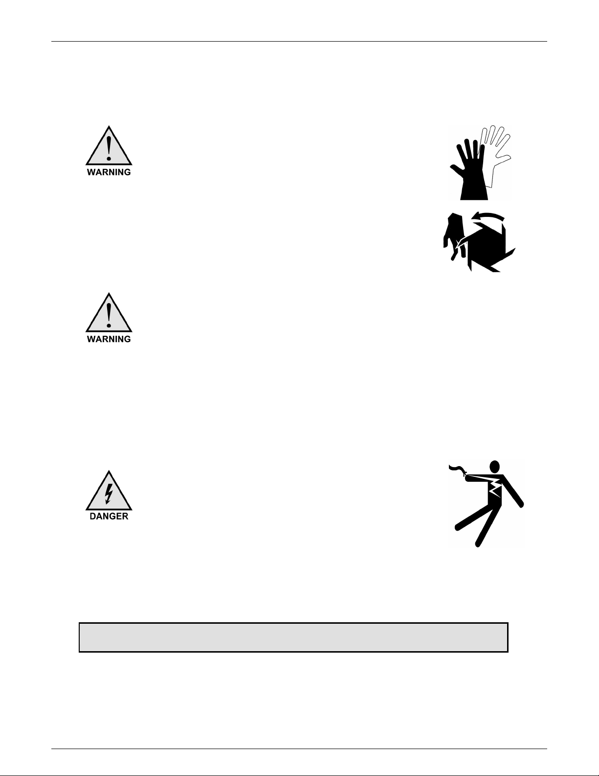
1.2 – SAFETY WARNINGS
SHARP EDGES:
It is advisable to wear gloves and use a block of
wood to move and "block" the rotor, or when
attempting to remove partially ground product or
service the PRS-20 blades.
Knives Are Extremely Sharp!! Use extreme
caution when placing your fingers or hands near
the rotor knives.
Maguire Products, Inc.
DOOR SAFETY INTERLOCK:
There are 4 safety interlocks switches on the front and rear doors
as well as one safety interlock switch on the PRS-20’s containment
chamber. If you open any of the doors or containment chamber,
all operations will stop. After closing the doors, you will need to
restart the PRS-20 properly. If Operation is abruptly stopped a
possible material jam may occur. See Clearing a Jam for more
information.
RISK OF SHOCK:
Disconnect power supply before servicing the
PRS-20.
DO NOT OPEN electrical box without disconnecting
power.
GETTING STARTED: PROCEED TO: INSTALLATION - NEXT PAGE
Edition: June 20, 2012 – PRS-20
9

Maguire Purging Recovery System
Maguire Products, Inc.
1.3 – Purging Recovery System Terminology
Bed Guides
Bed Knife
Blower
Containment Chamber Hopper in which parts are placed & contained during processing
Cylinders
Discharge Chute
Follower Plate
Front of Machine
Granulator
Grip Latches
Home Position
Jack Screw Block
Lifting Channels
Limit Switches
Lower Table
White polypro strips running along the outside of the PRS-20’s
tables. These strips provide minimal clearance from the bottom of
the containment chamber to the guide preventing material from
leaking out during processing.
2nd Stage Adjustable knife determining gap (clearance) to rotor
knife. All four edges of this knife are sharpened for maximum life.
Material movement system positioned below grinder
(1) pneumatic, (1) hydraulic that move containment chamber &
monitor pressure changes for protection against jamming
Chute which material drops into after being cut by R- Nine
Polypropylene plate that lowers onto scrap parts being processed.
Keeps material close to shredder rotor for efficient processing
Hinged doors in center. (drive motors are on back of machine)
Machine designed to size reduce material to chips/granulate
(1) located on each side on front of containment chamber keeping
cover securely closed.
Containment chamber is stopped over upper table & in contact with
table limit stop
White polypro blocks located on exterior lower right comers of
containment chamber. These blocks have a jam nut and a socket
head set screw in them. When wheel assemblies are loosened,
these blocks provide hopper clearance adjustment over bed guides.
Two rectangular slot in front face of sound enclosure. These slots
allow forklift access so machine can be moved.
Switches, which immediately terminate electrical current upon
activation. (Located on sound enclosure doors & containment
chamber cover)
Located to left of rotor when viewed from front of machine
10
Edition: June 20, 2012 – PRS-20

Maguire Purging Recovery System
Maguire Products, Inc.
Regulator
Allows compressed air line to be connected. Regulates air pressure
to pneumatic cylinders. (Do not adjust from factory setting of 90 psi
without consulting Maguire Products
Reversing Circuit
Monitors resistance encountered during containment chamber
travel. When resistance is met, unit reverses travel preventing
overfeeding or jamming.
Lower Radial Granulator Performs 2nd stage of grinding (located under tables)
Rotor
Machined cutter with mounted knives
Rotor Knife
Fixed (non-adjustable) knife that is bolted to rotor
Screen Ring
Removable ring with drilled holes, which dictate particle size
(located in Lower Radial Granulator)
Sensing Switch
Switch mounted between hydraulic cylinder inlet/outlet. This switch
monitors hydraulic fluid movement. When no movement of fluid is
detected for 2 seconds, (i.e. a "jam" condition) hopper will reverse
direction.
Shredder
Process where rotor performs 1st stage of grinding (located
between upper & lower tables)
Shuttle
Describes "Back & forth" movement of containment chamber
Sound Enclosure
Sound dampened panels mounted to machine minimizing DBA
level.
Stripper Plate
Machined plate mounted to lower bed with scalloped design.
Prevents long pieces of processed parts from making their way into
transition discharge.
Timer
Adds additional runtime after Shuttle Empty Alarm.
Transition Discharge
Removable chute that directs shredded material into Lower
Granulator.
Upper Table
Located to right of shredder rotor when viewed from front of
machine
Wiper Blades
Adjustable aluminum strips mounted to bottom of containment
chamber. Prevents material from escaping containment chamber &
keeps upper & lower tables free of debris.
Edition: June 20, 2012 – PRS-20
11

Maguire Purging Recovery System
Maguire Products, Inc.
Purging Recovery System Concept
The Maguire Purging Recovery System is a low cost alternative to
conventional size-reduction of any large parts or purgings. This
completely new type of plastics granulator automatically transforms
large reject parts, purgings and other bulky or difficult-to-handle scrap
into high-quality regrind but costs substantially less than conventional
equipment. Until now, size-reducing large parts has meant buying a
massive heavy-duty granulator, using a shredder in combination with a
standard granulator, or cutting the parts with a saw before granulation.
The PRS-20 is a two-stage system that in the first stage literally planes
reject parts into small pieces. In this “planing” stage the scrap or reject
part is automatically shuttled back and forth over a table surface that is
split into two levels like a carpenter’s plane. Mounted in between the two
levels is a staggered knife rotor that turns at 1750 rpm. This rotor
reduces the scrap into small pieces and propels them into the hopper of a Radial Granulator. This
Radial Granulator is positioned directly below the planer and performs the second stage by size
reducing the pieces into highly uniform regrind meeting the particle size requirement of your operation.
The final particle is then removed from the discharge chute by the Maguire Blower system & conveyed
to a gaylord for storage.
PRINCIPLES OF OPERATION
•
The operator places the plastic part or bulk scrap into the containment chamber, or hopper,
which is parked, at the home position at the upper level table. The containment chamber has
two cylinders mounted to it. The first cylinder is pneumatic and solely provides the movement of
the containment chamber. The second cylinder is hydraulic and has a switch mounted in-line,
which monitors the movement of the fluid in the cylinder. If there is no movement of fluid, such
as a jam condition, the switch senses this and reverses the hoppers direction of movement. The
hydraulic cylinder also provides excellent shock absorbent qualities during the grinding process
and containment chamber movement.
•
Upon push-button activation by the operator, the follower plate releases and applies gentle
pressure on the parts) being ground. The containment chamber shuttles on wheels toward the
lower level table.
•
The scrap then passes over the rotor, which is turning in the same direction as the Shuttle's
movement.
•
When the containment chamber reaches the farthest end of the lower table it is restricted from
moving any further. The hydraulic sensor detects no movement in fluid and reverses the
containment chambers direction. The part is now being fed into the rotor knives, which are
turning into the part.
•
Small pieces produced by the rotor knife are propelled downward into the hopper of the Radial
Granulator for final size reduction.
•
The fine particles are removed from the Radial Granulator discharge chute by the blower. The
particle is conveyed through 3 inch tube into a gaylord container.
•
This shuttling process continues until the Hopper Empty Alarm or the operator manually stops
the machine for reloading.
12
Edition: June 20, 2012 – PRS-20

Maguire Purging Recovery System
2 - Installation
2.1 – Transport, Setup
The PRS-20 is shipped pre-assembled. The PRS-20 frame is designed with forklift fork
tubes and can be lifted using a forklift. The Granulator’s weight is 2500 lbs (1135 kg).
Protective wrap and wood may be attached to the PRS-20 and must be removed prior
to use.
Remove the crating surrounding your granulator.
The Granulator is bolted to the crate base using lengths of wood running through the
forklift tubes in the frame. Unbolt these boards and remove them.
Remove any strapping, securing tape or plastic wrap from the Granulator.
Your granulator has been equipped with lifting channels that allow forklift access. These
lifting channels are accessed from the front of the granulator.
Make sure all doors are secured closed and move your granulator to the location of your
choice.
Maguire Products, Inc.
Lifting
DANGER OF INJURY!
If the weight is unevenly distributed, the PRS-20 may tip and injure people
when it is lifted.
Lift the PRS-20 with a fork truck or suitable equipment. Weight of PRS-20 is
2500 (1134 kg). Lift points (fork tubes) are between the leveling feet,
oriented from front or rear. The forklift forks must be within the fork tubes
for stability when lifting.
Edition: June 20, 2012 – PRS-20
13

Maguire Purging Recovery System
2.2 – PRS-20 Installation
Electrical Connection
RISK OF INJURY! Only qualified technicians should
make electrical connections.
Connect Motor Power to PRS-20
After initial setup of the Granulator, the power cable must be
connected. The electrical cable is located on the left side of the
Granulator and supplies the power. Within the cable are four
wires. These wires are black, brown, blue and fourth wire is a
green/yellow wire is the ground wire.
WIRING YOUR GRANULATOR AND ASSURING PROPER ROTATION
The following procedure will guide you in supplying power to your granulator. Your
granulators requires a 20amp Breaker & is wired for 60 cycle / 3 phase.
1. Select The Proper Male Cord Cap To Match Your Electrical Supply.
2. Remove Approx. Four Inches Of Rubber Coating On Cord To Expose
Coated Wires.
3. Remove Approx. Y2 Inch Of Plastic Coating From Each Of The Four Leads.
4. Attach your Male Cord Cap as required by local code.
5. Plug Granulator Into Power Supply.
6. Turn the granulator power disconnect to the "ON" position.
Press The Start Button for the Blower, the grinder & 3rd sequence "Shuttle Rotor".
Maguire Products, Inc.
14
Edition: June 20, 2012 – PRS-20
Maguire Purging Recovery System
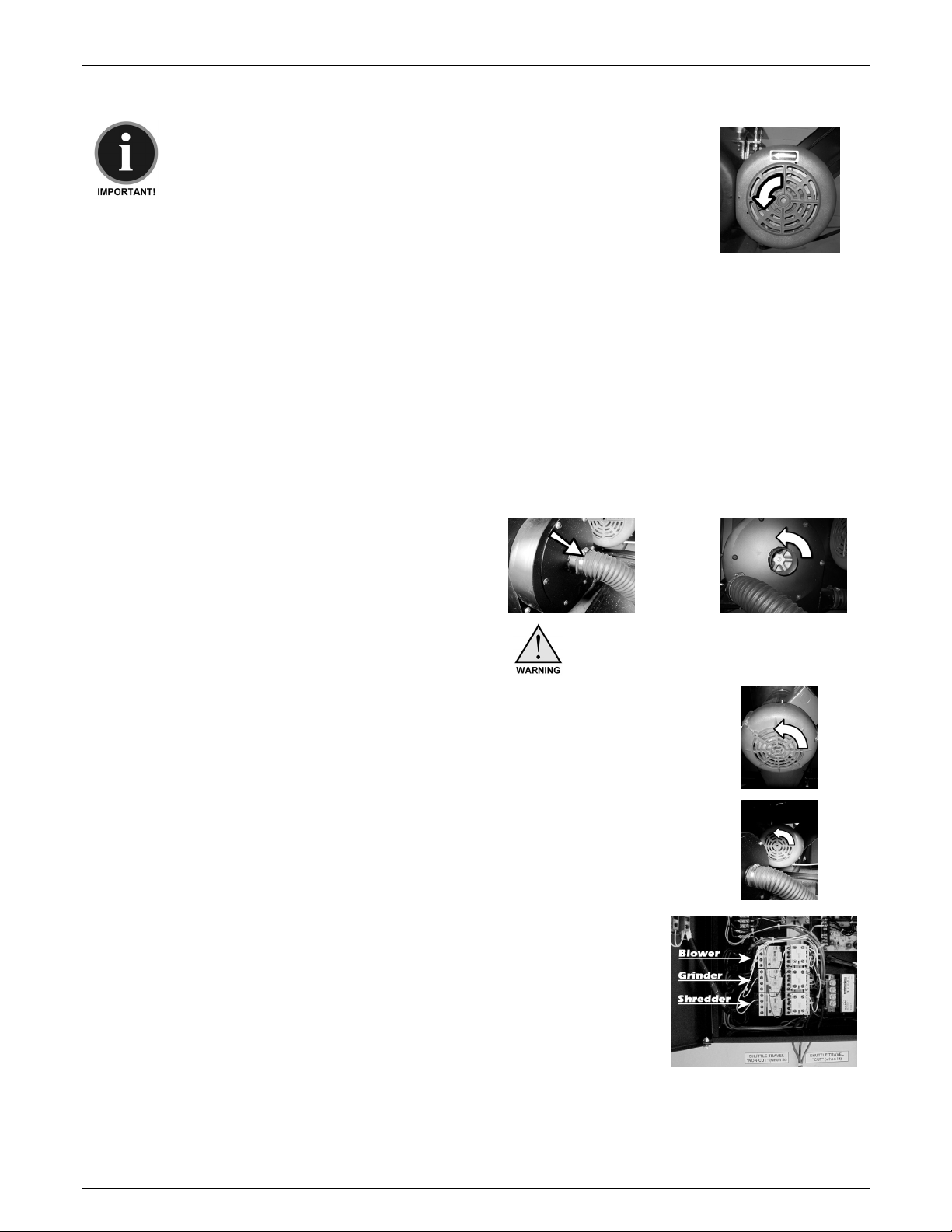
Check The Motors For Proper Rotation
Important: The blower, shredder & second stage motors all use
3-phase. Therefore, it is only necessary to assure that one
motor is turning in the correct direction. From the front of the
granulator, the shredder rotor should be turning in a
"counterclockwise" direction.
If The Motor Is Not Turning In The Correct Direction:
Maguire Products, Inc.
1. Turn Off The Grinder and follow proper lockout/tagout procedures.
2. Remove power cable from the power source.
3. DO NOT REMOVE THE GREEN GROUND WIRE.
4. Swap Any Two (2) Of The Other Three (3) Wires In The Lord Cap And Secure.
5. Reassemble Cord, Connect To Power Supply & Recheck For Proper Rotation.
If Proper Rotation Is Observe:
Supply the granulator with compressed air & assure regulator is set at 90 psi.
Follow this procedure if the PRS-20 has been serviced or it is necessary to check the
rotation of all 3 motors individually:
Blower Motor: The blower motor is located
within the front door below the
bed rails. Remove the black
convey line. Observe the
rotation during operation. It
should rotate in a counterclockwise direction.
DO NOT reach into the blower!
Grinder Motor: The grinder motor is located in the back of the PRS-
20 below the bed rails. Observe the rotation during
operation. It should rotate in a counter-clockwise
direction.
Shredder Motor: From the front of the granulator, the shredder rotor
should be turning in a "counterclockwise" direction.
If any ONE of the three motors are not turning in The Correct
Direction (counter-clockwise), then follow these steps:
1. Turn Off The Grinder, follow proper lockout/tagout procedures.
2. Remove power cable from the power source.
3. Open the Electrical cabinet and locate the motor starter
contactors / overload relays. See labeled photo at right.
4. Located the specific relay that needs to be corrected.
5. Swap any two (2) of the other three (3) wires and secure.
Connect To Power Supply & Recheck For Proper Counter-clockwise Rotation.
Edition: June 20, 2012 – PRS-20
15
 Loading...