


MAGUIRE PRODUCTS INC.
LoPro
TM
Receiver
TM
TM
LoPro
LoPro
LoProLoPro
TMTM
Receiver
Receiver
ReceiverReceiver
INSTRUCTION MANUAL
Copyright Maguire Products, Inc. 2019

L o P r o R e c e i v e r
Maguire Products Inc.
Maguire Products Inc.
Maguire Products Inc.Maguire Products Inc.
M A G U I R E P R O D U C T S , I N C .
Model
Table of Contents
Model LPR
Model Model
LPR----A7 & LPR
A7 & LPR----A12
LPRLPR
A7 & LPRA7 & LPR
A12 LoPro Receiver
LoPro Receiverssss
A12A12
LoPro ReceiverLoPro Receiver
Principle of Receiver Operation __________________________________________ 4
Principle of Controller Operation ________________________________________ 4
Description of Controls _________________________________________________ 6
Installing the LoPro Receiver ____________________________________________ 7
Filter Cleaning or Replacement __________________________________________ 9
MCP & 3rd Party Pump _________________________________________________10
Wiring Diagrams _____________________________________________________ 11
Dimensional Drawings ________________________________________________ 14
Warranty ___________________________________________________________ 12
Technical Support and Contact Information ______________________________ 13
2
Rev: January 15, 2019

L o P r o R e c e i v e r
M A G U I R E P R O D U C T S , I N C .
Copyright 2019 Maguire Products Inc.
The information contained within this manual including any translations thereof, is the property of
Maguire Products Inc. and may not be reproduced, or transmitted in any form or by any means
without the express written consent of Maguire Products Inc.
To every person concerned with use and maintenance of the Maguire LoPro Receiver it is
recommended to read thoroughly these operating instructions. Maguire Products Inc. accepts no
responsibility or liability for damage or malfunction of the equipment arising from non-observance of
these operating instructions.
To avoid errors and to ensure trouble-free operation, it is essential that these operating instructions
are read and understood by all personnel who are to use the equipment.
Should you have problems or difficulties with the equipment, please contact Maguire Products Inc.
or your local Maguire distributor.
These operating instructions only apply to the equipment described within this manual.
Accuracy of this Manual
We make every effort to keep this manual as correct and current as possible. However, technology
and product changes may occur more rapidly then the reprinting of this manual. Generally,
modifications made to the pump design or to the operation of the software are may not reflected in
the manual for several months. The date at the footer of this manual will indicate approximately how
current this manual is. Likewise, your pump may have been produced at an earlier time and the
information in this manual may not accurately describe your pump since this manual is written for
the current line of pumps in production (as of the date in the footer). We always reserve the right to
make these changes without notice, and we do not guarantee the manual to be entirely accurate. If
you question any information in this manual, or find errors, please let us know so that we may make
the required corrections or provide you with accurate information. Additionally, we will gladly provide
you with an updated copy of any manuals you need at any time. We welcome comments and
suggestions on ways we can improve this manual. For additional information, or to download the
latest copy of this manual or any other Maguire manual, please visit our website or contact us
directly.
Manufacturer’s Contact Information
Maguire Products Inc.
11 Crozerville Road
Aston, PA. 19014
Phone: 610.459.4300
Fax: 610.459.2700
Website: http://www.maguire.com
Email: info@maguire.com
Rev: January 15, 2019
3

L o P r o R e c e i v e r
M A G U I R E P R O D U C T S , I N C .
Principles of Receiver Operation
The LoPro is a material conveying receiver. Being that of a receiver, this unit requires the
addition of a stand-alone vacuum pump. The Maguire MCP pump is specially designed for this
purpose. A third-party pump control (part #: OPL-LPR-AVB) is also offered, so LoPro receivers
can be used with larger vacuum pump systems as well.
The LoPro will also require a regulated, non-lubricated 80 psi (5.5 Bar) compressed air
supply. This model incorporates a pneumatic vacuum shift valve, and filter clearing blow-off which
rely on this air supply.
A unique feature of this LoPro unit is the vertical height. While many other material loaders
and receivers can protrude 2 to 3 feet out the top of a hopper lid, the LoPro stands only 7-5/8”
(193 mm) out of a hopper lid. Despite its low clearance, it maintains a respectable capacity.
Another unique feature of the LoPro are their large opening for material discharge. This
large opening helps to provide fast, effective flow of any type of material from the receiver.
Principle of Controller Operation
The LoPro is powered with 24 VDC, which is supplied exclusively from the pump which it
is connected to via its signal cable. Multiple LoPro units can be wired to other each other so that
they all share a single pump (depending on throughput, on average up to 8 units, per pump).
The controller logic works off a first-in, first-out priority order. Adding receivers requires no
additional programming sequence or setup. Operators simply attach the next receiver’s input
connector to any other receiver’s output connector using a signal cable.
The LoPro receiver obtains its demand signal from the positioning of its counter-weighted
dump flap via a magnetic sensor. When a hopper is empty, the dump flap of the receiver will
swing shut, telling the it to run a loading cycle. When a LoPro has filled the hopper, the material
inside the hopper will hold the dump flap open, indicating not to run.
Alarm Routine
If a LoPro is running and material is not successfully being conveyed, an alarm will sound
indicating this to the operator. The receiver is able to detect this by observing the signal from
the dump flap sensor. At the end of the loading cycle, material should flow out of the receiver
causing the dump flap to temporarily swing open. The controller will see this happen; thus,
verifying material was successfully conveyed.
If the LoPro detects that material is not conveyed 5 consecutive times, the receiver will
enter an alarm routine to alert the operator. The alarm routine consists of 5 more loading
attempts with the alarm (buzzer) active, followed by a 2 min wait period. This sequence will
repeat until LoPro detects material being conveyed, or the alarm routine is exited by the
operator.
While the receiver is alarming, an operator can manually exit the alarm routine by
pressing the “set time” pushbutton twice (1st to silence the alarm, 2nd to exit the alarm routine
completely). Whether the alarm routine is exited naturally or manually, the LoPro will then
resume its standard operating procedure.
4
Rev: January 15, 2019

L o P r o R e c e i v e r
M A G U I R E P R O D U C T S , I N C .
Set Time
The “Set Time” pushbutton is primarily used to set the duration of time that the LoPro will
convey material for during a loading cycle. The time is defaulted to 25 seconds, but can be set
anywhere from 5 to 45 seconds. Depending on the material’s density, an operator may want a
duration which is longer, or shorter. Adjusting this time interval is very easy. Simply wait until the
loader begins conveying material normally. While it is doing this, press and hold the “Set Time”
pushbutton. After the desired time duration has passed, let go of the “Set Time” pushbutton.
The new conveying duration will be from when the LoPro began loading initially, to when you
released the “Set Time” pushbutton. The LoPro will save this duration even after power has
been cycled. An operator can adjust this as many times as they feel necessary.
Operational Modes
Out of the box, the Lopro receiver is set to run anytime a demand signal is present. This
demand signal is determined by the hanging position of the dump flap. For conveying
applications where material may not always available (such as regrind), the operator may want
to set the receiver to one of the 4 additional non-continuous, or “regrind” modes.
These additional modes differ from the standard operating mode such that a delay is
incorporated in between loading cycles. Additionally, the alarm routine is disabled when set to
any of the 4 regrind modes.
Properly using one of these modes can help to prevent unnecessary vacuum motor
operation.
Directions on how to set, or exit regrind mode in the Lopro are as follows:
1) Power Lopro controller off (rocker switch on front panel switched down)
2) While holding the “SET TIME” button down, turn controller power on.
3) Continue to hold the “SET TIME” button down until the status LED blinks once, then
immediately let go of the “SET TIME” button.
4) LED blinks once after a few seconds.
5) Release set time button.
6) Immediately press set time button 1 through 5 times to enter one of the 5 different
modes. Here is a list of what operating parameters are associated with:
(Pressed 1 time) - Exit Regrind mode (default, alarm active, zero delay)
(Pressed 2 times) - 2 min delay after each cycle (alarm disabled)
(Pressed 3 times) - 4 min delay after each cycle (alarm disabled)
(Pressed 4 times) - 8 min delay after each cycle (alarm disabled)
(Pressed 5 times) - 16 min delay after each cycle (alarm disabled)
After the set time button has been pressed the desired amount of times, there will be a pause
for several seconds, and then the receiver’s status light will blink back what was just set
(example: 3 blinks for 3 button presses).
Following this, nothing else is required from the operator. The receiver will boot up in the mode
that was just set. The receiver will remember this setting if power is cycled. An operator can
adjust this as many times as they feel necessary.
Rev: January 15, 2019
5
L o P r o R e c e i v e r
M A G U I R E P R O D U C T S , I N C .
Status Indicator
The LoPro’s status indicator is a green LED located on the front panel of the controller.
Primarily, this is used to indicate if the unit is powered up, but also serves several other
purposes. As mentioned earlier, the status indicator is an integral part of setting the LoPro’s
running mode.
The status indicator will provide information about the LoPro during standard operation.
This can be a useful tool for troubleshooting. At any point when the LoPro is turned on, the
status indicator should be displaying 1 of 4 conditions. The following list describes each, and
explains what each one means:
• Constantly Illuminated: Satisfied. Not calling for material, presumably hopper full.
• 1-Second flash rate: Waiting. Calling for material, but line is currently in use by
another receiver.
• ¼ Second flash rate: Loading. In the process of conveying material.
• Rapid (1/20th second) flash rate: Alarming. Could be anywhere within the alarm
routine (see description on page 4).
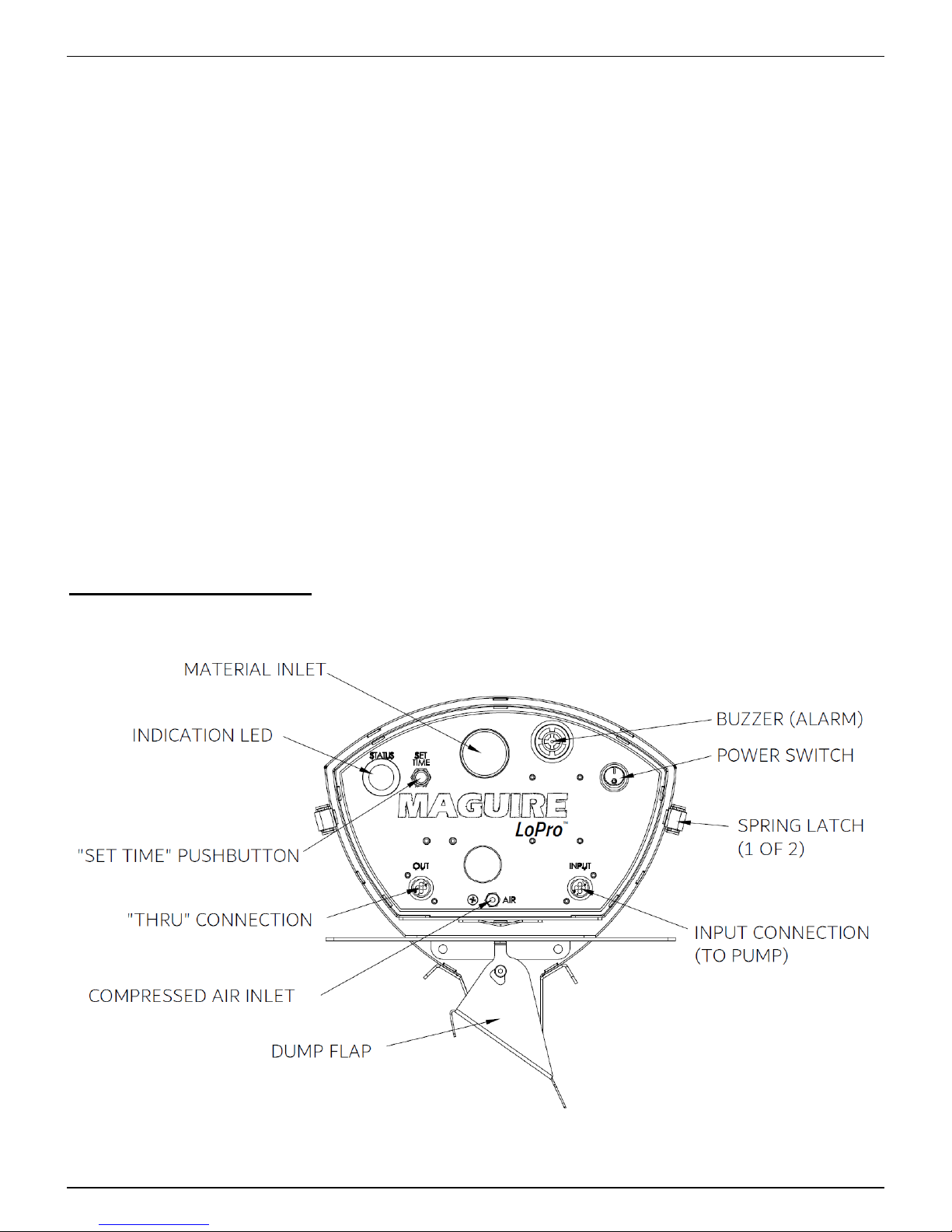
Description of Controls
6
Rev: January 15, 2019

L o P r o R e c e i v e r
M A G U I R E P R O D U C T S , I N C .
Installing the LoPro Receiver
1. Install flexible hose, secured with hose clamps at both ends, from feed tube to material inlet tube on
the front of loader (same side as controller).
2. Install flexible hose, secured with hose clamps at both ends, from vacuum pump to vacuum inlet of
receiver (opposite side as material inlet).
3. Install 5/32” (4 mm) air line into the fitting and connect to clean, dry 80 psi (5.5 bar) compressed air
supply. DO NOT apply direct air pressure to the LoPro fitting. Damage or an air leak could result.
A compressed air filter (sold separately) is recommended for protection of pneumatic components.
4. Connect the 4-pin power/signal cable to the receptacle labeled “INPUT” on the front panel of the
Lopro. Connect other end of cable to pump (or another LoPro’s “OUT” receptacle that has already
been attached to a pump).
5. Attach pump (shown with Maguire MCP) to electrical power source (120 or 230 volts AC depending
on model), then turn on.
6. Rotate the feed tube ring for the best air to material mixture. The best mixture of air and material
will allow material to flow efficiently, with the right proportion of conveying air, without clogging and
without rapid hose wear.
Rev: January 15, 2019
7

L o P r o R e c e i v e r
M A G U I R E P R O D U C T S , I N C .
Filter Cleaning or Replacement
1) Turn off power on loader.
2) Disconnect the material line, signal cable, and compressed air.
3) Release spring latches, and remove controller portion.
4) Remove / replace filter (Maguire part #: ashffd4). Dome side of filter facing toward the material
portion.
5) When reinstalling the controller portion of the receiver, make sure that the material inlet is lined up
and slides in smoothly into the respective grommet. Then, fasten the 2 spring latches.
8
Rev: January 15, 2019

L o P r o R e c e i v e r
Accessing electronics, valves for service
To access the electronics of the Lopro receiver, remove the (7) sheetmetal screws holding in the
front panel. Remove only the front panel.
M A G U I R E P R O D U C T S , I N C .
Replacement Parts:
Part Description
4.5” dia. Dacron filter with foam gasket
Solenoid, 3-way, 24 VDC
Circuit Board
“Status” Indicator LED, 22mm, 24V Green
“ON/OFF” Rocker Switch
Piezo Alarm Buzzer, 24VDC
Maguire Part Number
ashffd4
nv91
eab-LPL-R
ehl-24G
eswr06
ehb-2
Rev: January 15, 2019
9

L o P r o R e c e i v e r
M A G U I R E P R O D U C T S , I N C .
MCP Pump & 3rd Party Control Options
Maguire MCP
The MCP pump is a simple, compact vacuum system specifically designed for LoPro recieivers systems.
• Features a brushless motor which last 4 to 5 times as
long as equivalent motors with brushes.
• Capable of providing vacuum power for systems up to
1,000 lbs/hr.
• Hinged lid for quick cleanout.
• 1-1/2” Vacuum inlet
• Available in both 120V and 230V models.
3rd Party Pump Control Module
LoPro receivers can be run with a 3rd party pump by using the 3rd party pump control module.
Part number: LPR-PC-O
This module can be used to run most vacuum pumps.
It will interfaces using 24 Vdc outputs to operate a motor contactor and vacuum bypass valve.
10
Rev: January 15, 2019

L o P r o R e c e i v e r
Wiring Diagrams
LPR Controller
M A G U I R E P R O D U C T S , I N C .
Rev: January 15, 2019
11

L o P r o R e c e i v e r
MCP Pump
M A G U I R E P R O D U C T S , I N C .
12
Rev: January 15, 2019

L o P r o R e c e i v e r
3rd Party Pump Control Module
M A G U I R E P R O D U C T S , I N C .
Rev: January 15, 2019
13

L o P r o R e c e i v e r
Dimensional Drawings
M A G U I R E P R O D U C T S , I N C .
14
Rev: January 15, 2019

L o P r o R e c e i v e r
M A G U I R E P R O D U C T S , I N C .
Rev: January 15, 2019
15

L o P r o R e c e i v e r
M A G U I R E P R O D U C T S , I N C .
WARRANTY - Exclusive 5-Year
MAGUIRE PRODUCTS offers one of the MOST
COMPREHENSIVE WARRANTIES in the plastics
equipment industry. We warrant each Pump
manufactured by us to be free from defects in
material and workmanship under normal use and
service; our obligation under this warranty being
limited to making good at our factory any Feeder
which shall within FIVE (5) YEARS after delivery to
the original purchaser be returned intact to us,
transportation charges PREPAID, and which our
examination shall disclose to our satisfaction to have
been thus defective; this warranty being
expressly in lieu of all other warranties expressed or implied and of all other
obligations or liabilities on our part, and MAGUIRE PRODUCTS neither assumes
nor authorizes any other persons to assume for it any other liability in connection
with the sale of its products.
This warranty shall not apply to any Feeder which shall have been repaired or
altered outside MAGUIRE PRODUCTS factory, unless such repair or alteration was,
in our judgment, not responsible for the failure; nor which has been subject to
misuse, negligence or accident,
incorrect wiring by others, or installation or use not in accord with instructions
furnished by Maguire Products.
Our liability under this warranty will extend only to Feeders that are returned to our
factory in Aston, Pennsylvania PREPAID.
It should be noted, however, that we strive to satisfy our customers in whatever
manner is deemed most expedient to overcome any problems they may have in
connection with our equipment.
16
Rev: January 15, 2019

L o P r o R e c e i v e r
Technical Support and Contact Information
Maguire Products Inc.
11 Crozerville Road
Aston, PA 19014
Tel: 610.459.4300
Fax: 610.459.2700
Email: info@maguire.com
Web: www.maguire.com
Maguire Europe
Tame Park
Tamworth
Staffordshire
B775DY
UK
Tel: + 44 1827 265 850
Fax: + 44 1827 265 855
Email: info@maguire-europe.com
M A G U I R E P R O D U C T S , I N C .
Maguire Products Asia PTE LTD
Main Office
15 Changi North Street 1
#01-15, I-Lofts
Singapore 498765
Tel: 65 6848-7117
Fax: 65 6542-8577
E-mail: magasia@maguire-products.com.sg
Rev: January 15, 2019
17
 Loading...