

MAGUIRE LPD-30, LPD-200, LPD-100 Maintenance Manual

MAGUIRE PRODUCTS INC.
LPD® Dryer
Models:
• LPD-30
• LPD-100
• LPD-200
LPD®
Low Pressure Dryer ®
INSTALLATION • OPERATION • MAINTENANCE
Copyright © Maguire Products, Inc. 2010

LPD Dryer®
Maguire Products, Inc.
2
Edition: Nov ember 5, 2010

LPD Dryer®
Maguire Products, Inc.
Maguire LPD ® - Low Pressure Dryer ®
Copyright
© 2010 Maguire Products Inc.
The information contained withi n this manual including any translations thereof, is the property of
Maguire Products Inc. and may not be reproduced, or transmitted in any form or by any means
without the express written cons ent of Maguire Products Inc.
To every person concerned with use and maintenance of the Maguire LPD® it is recommended
to read thoroughly these operating instructions. Maguire Products Inc. accepts no responsibility
or liability for damage or malfunction of the equipment arising from non-observance of these
operating instructions.
To avoid errors and to ensure trouble-free operation, it is essential that these operating
instructions are read and understood by all personnel who are to use the equipment.
Should you have problems or difficulties with the equipment, please contact Maguire Products
Inc. or your local Maguire distributor.
These operating instructions only apply to the equipment described within this manual.
Manufacturer’s Contact Information
Maguire Products Inc.
11 Cr oze r v ille R oad
Aston, PA. 19014
Phone: 610.459.4300
Fax: 610.459.2700
Website: http://www.maguire.com
Email: info@maguire.com
Edition: Nov ember 5, 2010
3

LPD Dryer®
Accuracy of this Manual
Maguire Products, Inc.
We make every effort to k eep this manual as correct and current as possibl e.
However, technology and product changes may occur mor e rapi dly then the
reprinting of this manual. Generally, modifications made to the dryer design or to
the operation of t he sof tware are may not reflected in the manual f or sever al
months. The date at the foot er of this manual will indicate approxim ately how
current this manual is. Likewise, your Dryer may have been produced at an
earlier time and the information in this manual may not accurately describe your
Dryer since this manual is written for the current line of Dryers in pr oduc tion (as of
the date in the footer). We always reserve the right to make these changes
without notice, and we do not guarantee the manual to be entirely accurate. If you
question any information in this manual, or find er r or s, please l et us know so that
we may make the requir ed correc tions or provide you with accurate information.
Additionally we will gladly provide you with an updated copy of any manuals you
need at any time. We welcome comment s and suggestions on ways we can
improve this manual.
For additional information, or to download the l atest copy of this manual or any
other Maguir e manual , please visit our website or contact us di r ectly.
On the Web at: www.Maguire.com
Maguire Products Inc.
Main Headquarters
11 Crozerville Road
Aston, PA 19014
Tel: 610.459.4300
Fax: 610.459.2700
Email:
info@maguire.com
Maguire Europe
Tame Park
Tamworth
Staffordshire
B775DY
UK
Tel: + 44 1827 265 850
Fax: + 44 1827 265 855
Email:
info@maguire-europe.com
Maguire Products Asia PTE LTD
Main Office
No. 15 Changi North Street 1
#01-15, I-Lof t s
Singapore 498765
Tel: 65 6848-7117
Fax: 65 6542-8577
magasia@maguire-products.com.sg
Maguire Italy
Via Zancanaro 40
35020 Vigorovea (PD)
Tel: +39 049 970 54 29
Fax: +39 049 971 18 38
Email:
info@maguire-italia.it
Please e-mail c omments and suggestions to: support@maguire.com
4
Edition: Nov ember 5, 2010

LPD Dryer®
Table of Contents
PART 1 GETTING STARTED, READ THIS PAGE 7
1.1 5 Year Warranty and Disclaimers 8
1.2 SAFETY Warnings 9
PART 2 INSTALLATION
2.1 Transport and Setup 10
2.2 Dryer Installation 11
2.2.1 Hopper Installation Series 30 11
2.2.2 Hopper Installation Series 100 / 200 12
2.2.3 Canister Installation Series 200 13
2.2.5 Electrical Connection 14
2.3 Installing Maguire Receiver on Process Machine 15
2.4 Using Your Own Receiver / Loader 16
2.5 Using the Maguire Receiver to load the Dryer 17
2.6 Dual Convey Option 19
PART 3 OPERATION
Maguire Products, Inc.
10
2.2.4 Compressed Air Connection 13
23
3.1 Standard Operation 23
3.2 Recommended Cycle Times 24
3.3 Standard Operating Sequence 25
3.4 Operating Features/Options 26
3.4.1 Convey-Only Mode 27
3.5 Changing Color “On The Fly” 28
3.6 Controls Description
3.6.1 Controller & Operator Station 29
3.6.2 Keypad 34
3.6.3 Star Functions 37
3.6.4 Parameters 50
3.6.5 Changing / Saving Parameters 60
29
Edition: Nov ember 5, 2010
5

LPD Dryer®
Maguire Products, Inc.
PART 4 MAINTENANCE AND SERVICE
4.1 Clean / Replace Air Filter 63
4.2 Cleaning the Vacuum Takeoff Assembly (VTA) 64
4.3 Canister Removal / Cleaning 66
4.4 Fill Hopper and Fill Valve Cleaning 69
4.5 Clean / Inspect the silicone disk seals 71
4.6 Drain and purge Air Filter / Regulator 71
4.7 Adjustments 72
4.8 Check Out Procedure 75
4.9 Temperature and Pressure Verification 76
4.10 Control Panel Removal 77
4.11 Diagnostic / Test Mode 77
4.12 Control Inputs and outputs
4.13 Decommissioning and Disposal 80
63
78
PART 5 TROUBLESHOOTING / SOFTWARE 81
5.1 Alarms – Cause and Solution 81
5.2 Possible Service Issues 84
5.2.1 Loss of Vacuum 84
5.2.2 Damaged Vacuum Disks 84
5.2.3 Heater Safety Switches Tripped 85
5.2.4 Filter Clogged 85
5.3 Print Outputs 86
5.4 Material Not Drying Correctly 87
5.5 Dryer Software – Backup, Restore, Factory Reset 88
PART 6 General Information
6.1 - Models, Model Identification 89
6.2 - LPD Nomenclature / Order Code 90
6.3 - Features 91
6.4 - Our Design Philosophy 92
6.5 - Theory of Operation / Performance 93
6.6 - Warranty 94
6.7 – LPD wiring Diagram & Supplements 95
6.8 - Exploded View and Parts List 109
6.9 - Pneumatic Diagrams 121
6.10 - Technical Support / Contact Information 127
89
6
Edition: Nov ember 5, 2010

LPD Dryer®
1 - Getting Started – READ THIS PAGE
PLEASE READ THIS PAGE
You don't have to read the entire manual....
BUT...
PLEASE READ THE NEXT TEN PAGES.
It will take about 10 minutes.
THESE PAGES COVER:
Maguire Products, Inc.
Warranty and Disclaimers: What we Warranty and
what we ca nn ot pr om i se.
SAFETY Warnings: Safety warnings.
INSTALLATION: Assembly and setup.
OPERATION: What buttons to push.
MAGUIRE "LPD" Dryers are protected by U.S. patent 6,154,980.
Additional U.S. and International patents are pending.
GETTING STARTED:
PROCEED TO: WARRANTY AND DISCLAIMERS NEXT PAGE
Edition: Nov ember 5, 2010
7

LPD Dryer®
1.1 - Warranty – Exclusive 5-Year
MAGUIRE PRODUCTS offers THE MOST COMPREHENSIVE
WARRANTY in the plastics auxiliary equipment industry. We
warrant each MAGUI RE LPD DRYE R manufac tured by us to be
free from defects in material and workmanship under normal use
and service; excl uding only those items listed below as 'excluded
items'; our obli gation under this warranty being limited to making
good at our factory any Dryer which shall, within FIVE (5) YEARS
after deliv ery t o the ori ginal purchaser, be RETURNED intact t o us,
transportation char ges PREPAID, and which our examination shall
disclose to our satisfaction to have been thus defecti ve; this
warranty being expressly in lieu of all other warranties expressed
or implied and of all other obligations or liabilities on our part, and
MAGUIRE PRODUCTS neither assumes nor authorizes any other person s to as sume for it any other
liabilit y in connect ion with the sale of its Dryers.
This warranty shall not apply to equipment repaired or al tered outside MAGUIRE PRODUCTS INC.
factory, unless such repair or alteration was, in our judgment, not responsible for the failure; nor which
has been subject to mi suse, negl igence or accident, incorrect wiring by others,
or installation or use not in accord with instructions furnished by
Maguire Produc ts, Inc.
Our liabilit y under this warranty will extend only to equipment that is returned to our factory in Aston,
Pennsylvania, PREPAID.
Please note that we al ways strive to satisfy our customers in whatever manner is deemed most ex pedient
to overcome any pr oblem s they m ay have in connection with our equipment.
Excluded Items:
The ability of the canisters to hold vacuum will be compromi sed if the vacuum seal edge is damaged from
mishandli ng. W e do not warranty c anisters damaged from improper handl ing. We do, however, warranty
the seals.
Disclaimers – Production of faulty product
This dryer is of a new design. We have had exc ellent results in all tests performed to date, but we have
not tested every m aterial available to the plastics industry. Materials vary widel y throughout the industry.
We have not antici pated all possible materials, proc essing conditions, and requirements. We are not
certain that our equipment will perform properly in all instances. You must observe and v erify the
performance level of this equipment in your pl ant as part of your ov er all manufacturing process. You
must verify t o your own satisfaction that this lev el of performance meets your requirement s. We can not
be responsible f or losses due to produc t not dried correctly, even when due to equipment malfunction or
design incorrec t for your requirements; and/or any consequential losses due to our equipment not drying
material to your r equir em ents.
We will only be responsible to correct, repair, replace, or accept return for full refund, our equipment if it
fails to perform as designed, or we have inadvertently misrepresented our equipment for your appli cation.
If for any reason this disclaimer is not acceptabl e, we will ac c ept return of the equipment for full refund,
including freight costs both ways.
Maguire Products, Inc.
GETTING STARTED:
PROCEED TO: SAFETY WARNINGS NEXT PAGE
8
Edition: Nov ember 5, 2010
LPD Dryer®
1.2 – SAFETY WARNINGS
Maguire Products, Inc.
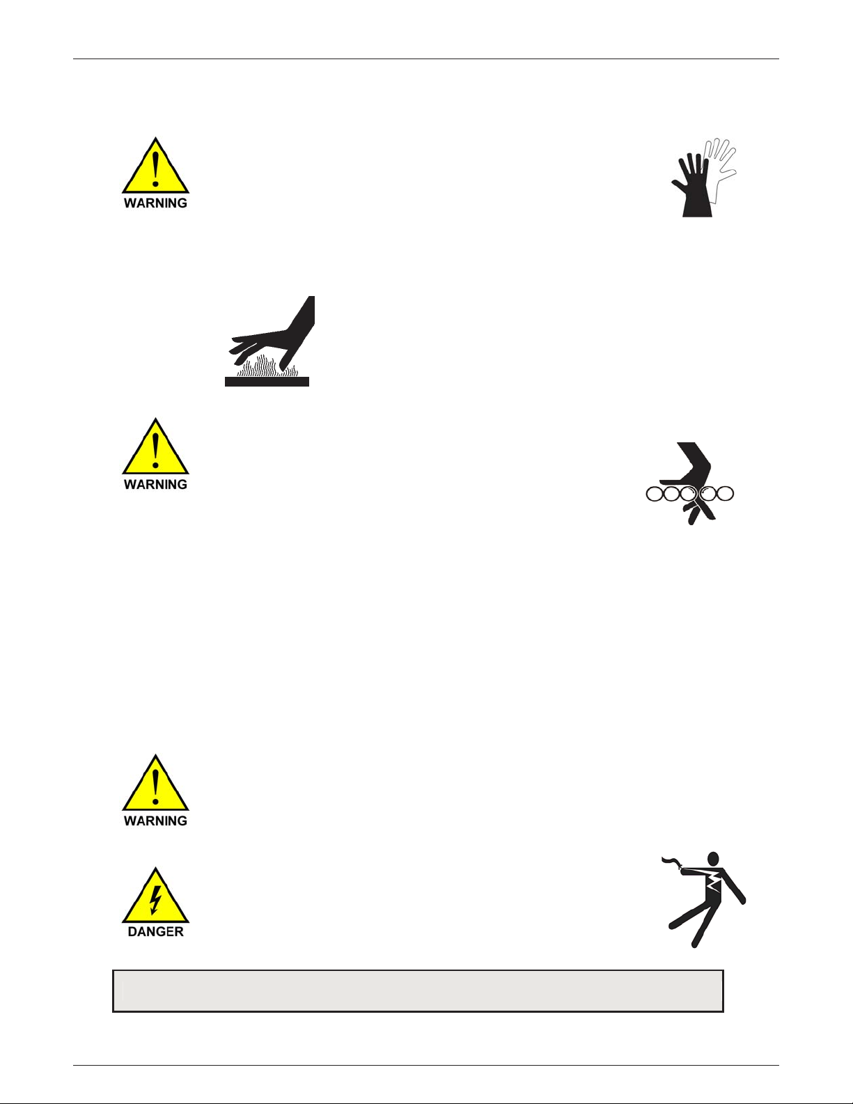
HOT SURFACES:
As with all dryers, there are HOT SURFACES to avoid. Temperatures
can reach 250F (120C), or 350F, (180C) on high temperature models.
All heated surfac es are contained within the exter nal encl osure.
When the door is opened you can access and touch hot surfaces. Typic ally these
surfaces are not at danger ous temperatures, however all hot surfaces should be
avoided.
Warning Label indicate HOT SURFACES
USE CAUTION when removing and instal li ng canisters.
USE GLOVES.
DO NOT REACH into the dryer enclosure.
INDEXING OF THE MATERIAL CANISTERS:
At the end of each cycle canisters automatically index.
The forces that cause rotation are light. However, the inertia of
already moving c anisters might cause injury. Additionally the
disks above and below each canister close automati c ally and
present a pinch poi nt. For these reasons an interlock on the access door prevents all
operations while the door is open.
DO NOT DEFEAT this in t e rloc k .
DO NOT try to index the canister s by hand, against the force of the positioni ng air
cylinder. They will swing back r apidly when released.
If you disconnect the air supply and then rotate the canisters by hand, rec onnec ting
the air will cause the c anister s to s wing r apidly back to their start position.
When connecting the air supply KEEP hands CLEAR. Have the DOOR CLOSED.
DOOR SAFETY INTERLOCK:
There is a safety interlock switch on the door. If you open the door, all oper ations will
stop. After closing the door, you will need to press START to restart the dryer.
Accumulated cycle time will not be lost.
RISK OF SHOCK:
Disconnect power supply before servicing the Dryer.
GETTING STARTED: PROCEED TO: INSTALLATION - NEXT PAGE
Edition: Nov ember 5, 2010
9
LPD Dryer®
Cut sides and top flaps, unscrew screws and washers from the sides at the skid.
Maguire Products, Inc.
2 - Installation
2.1 – Transport, Unpacking and Setup
To help you identify your Dryer see: LPD Nomenclature / Order Code on page 90.
Unpacking - Removing from Carton
There are 6 screw locations. Remove carton, remove cardboard tray at the top
of the carton. On Series 30 models, cut and remove plastic wire ties from
handles inside the dryer attached to the black frame member. On the Series 100
and 200 models, remove the packing material from around the canisters and
brackets.
Return Shipping Information
Lifting
DANGER OF INJURY!
If the weight is unevenly distributed, the Dryer may tip and injure
people when it is lifted.
Lift the Dryer with a fork truck or suitable equipment. Weights of
Dryer models range from 425 pounds (193 Kg) to 900 pounds (408
Kg). Lift points are between the wheels, oriented from front or rear.
The forks must be closest to the inside of the wheels as possible for
stability.
Remove Skid
Save the carton and cardboar d if at all possible, reuse for retur n to
factory. Use strong pl astic wire ties to affix the canister fr om tur ning on
the Series 30 units. On t he Series 100 and 200 models, it is advisable to
use packing material around the canister support br ac kets and ship t he
canisters on a separate skid or c ar ton.
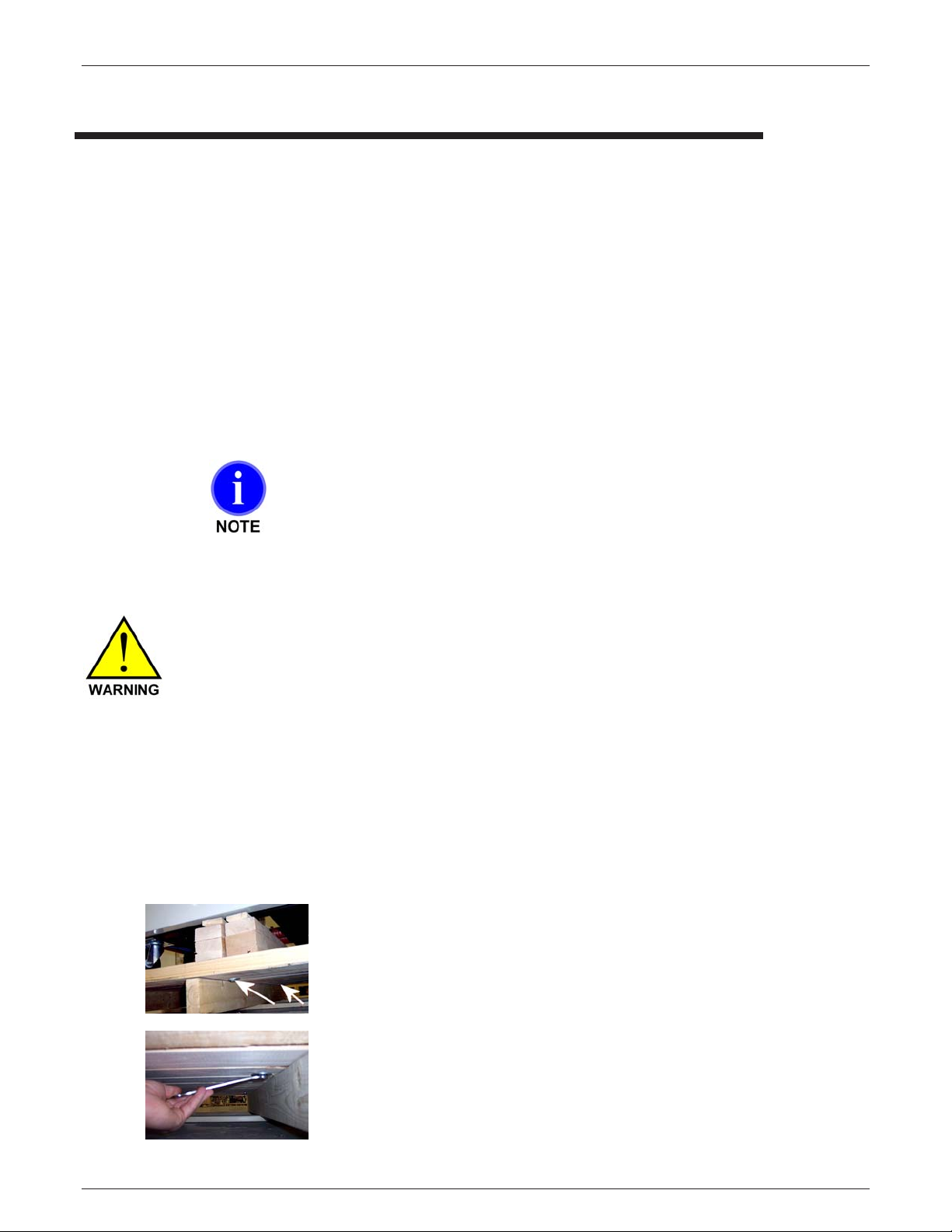
To remove the skid, unbolt the two bolts that secure the
dryer to the skid.
The bolts are located at the bottom of the Dryer and go
through the wooden skid. These bolts can be loosened
while the Dryer and the skid are on the ground. Reverse
procedure to install dryer on the skid.
10
Edition: Nov ember 5, 2010
LPD Dryer®
2.2 – Dryer Installation
2.2.1 - Hopper Installation on the Series 30 model Dryers
Maguire Products, Inc.
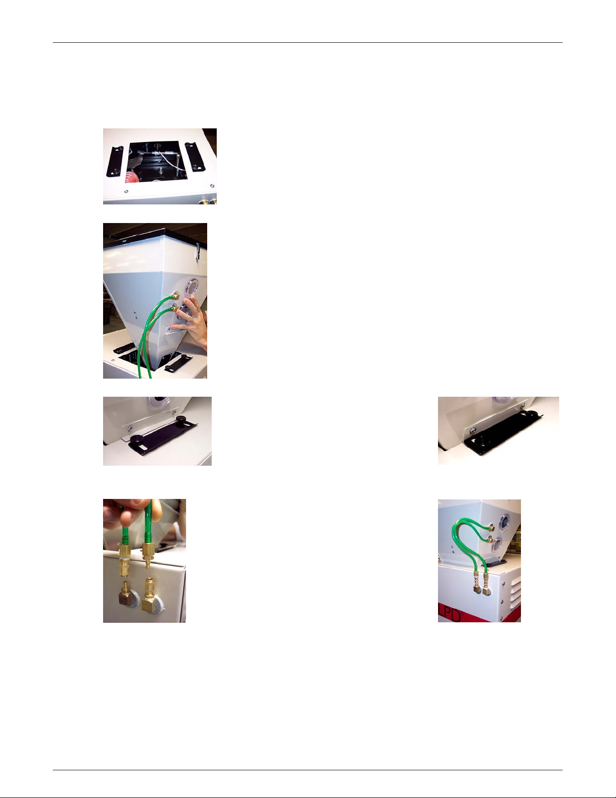
Loosen thumbscrews and slide plates away from opening.
Insert hopper into opening so that air supply hoses are
facing the same side of the Dryer as the fitting they will
attach to.
Slide both lock plates towards
hopper and over hopper flange.
Tighten thumbscrews.
Attach hopper air supply quick
connect fittings.
Edition: Nov ember 5, 2010
11
LPD Dryer®
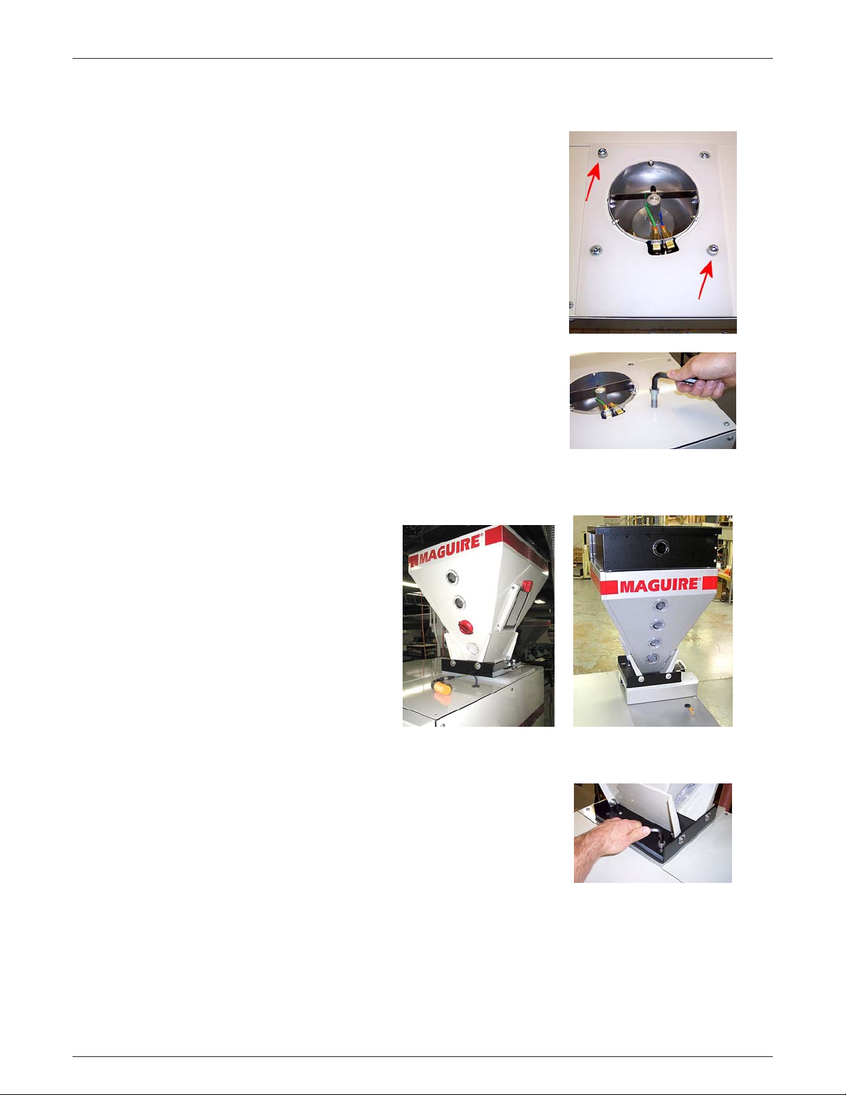
2.2.2 - Hopper Installation on the Series 100, 200, model Dryers
Locate and remove the two ½” SHCS fasteners and
washers on the fill hopper intake plate (on top of the
Dryer) using 3/8” Allen wrench.
Note: Do not remove the two recessed button head
fasteners.
Place the hopper on the dryer intake and line up the two
boltholes in the hopper with the boltholes in the fill
hopper intake plate.
For easy accessibility orientate the hopper so that the
manual slide gate handle and hopper access door are
accessible from the side or rear of the Dryer.
Maguire Products, Inc.
Note: LPD-200 Series is equipped
with a Cleanout Chute. The LPD200 hopper is elevated 2 7/8
inches higher than the LPD-100
hopper). For easy cleanout of the
LPD-200 hopper, orient the
hopper so the manual slide gate
handle is above the chute (right
side of dryer).
LPD-100
Re-install the two ½” SHCS fasteners and washers then
firmly tighten by hand using 3/8” Allen wrench.
LPD-200 Cleanout chute
12
Edition: Nov ember 5, 2010
LPD Dryer®
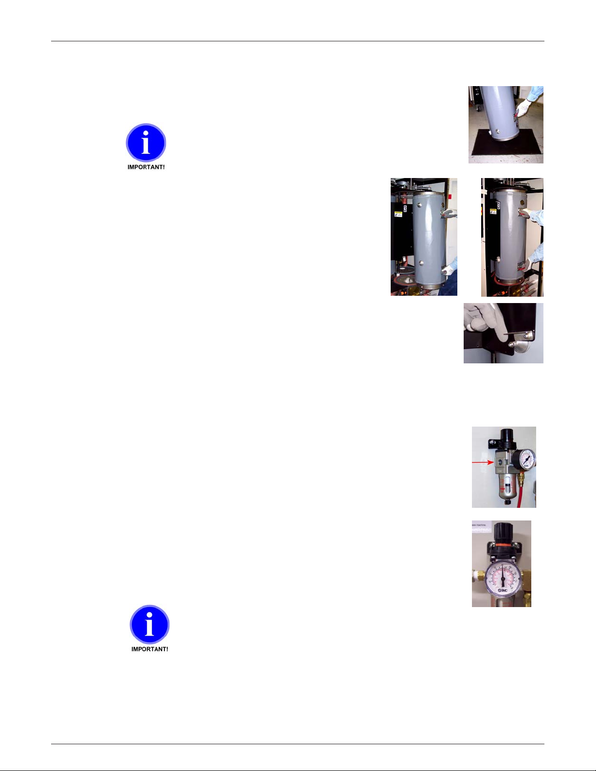
2.2.3 – Installing Canisters on Series 200 model Dryers
Maguire Products, Inc.
With 200 Series Dryers, the canisters are packaged separate from the Dryer
itself. To install the Canisters into the Dryer, follow these steps.
Do not damage the edge of the canister . Always rest the
canisters on a rubber mat or thick cardboard and take care
not to damage the edge of the canisters.
After unpacki ng the canisters, rest the canisters on a rubber
mat to protect the c anister edge. Open the Dryer door and
rotate the “Cani ster Hanger A ssembly” around to an empty
station. Grip the t wo handles of the canister firmly and lift the
canister up i nto t he Dryer, and hang the upper supports into
the “Canister Hanger A ssembly”, then swing the lower
supports back to t he lower l atches.
Hook the canister latch on each side of the canister by pushing the cani ster
back to the latch, securing the canister.
Note: Each canister hangs in one of three posi tions in the “Canister Hanger
Assembly”. These three P osi tions are labeled 1,2 and 3. The number identif ies
the canisters posit ion in the assembly.
2.2.4 - Compressed Air Connection
Connect an air suppl y to the ai r regulator’s IN port using a male ¼” NPT fitti ng.
An operating air pressure of 80 psi (5.5 bar) while the vacuum generator
is running is required for proper operation of the Dryer.
Note: The Vacuum Generate ru ns for the first few minutes of every cycle.
If your air supply has oil in it add an oil separator filter.
Oil in the air will combine with dust drawn from the canisters formi ng a paste
inside the vac uum generat or . It will stop working and require cleaning.
Observe the air pressure gauge t o be sure t he pr es sure maintains 80 psi (5. 5
bar) while the v acuum generator is running or activ ate the bl ow gun rel easing
air as you check and adjust t he r egulator. If pressure drops below 80 psi,
adjust the regulator. If the pressure cannot maintain 80 psi (5.5 bar) while the
vacuum generator is running, then the air supply line is not adequate.
Do not supply Dryer with a lubricated air supply. Damage to
Dryer may result. Use only a clean, dry , oil-free air supply.
Edition: Nov ember 5, 2010
13
LPD Dryer®
Maguire Products, Inc.
2.2.5 - Electrical Connection
To help you identify your Dryer see: LPD Nomenclature / Order Code on page 90.
RISK OF INJURY! Only qualified technicians should
make electrical connections.
Connect power to a properl y fused disconnect.
Voltage and amp ratings are speci fied on the serial num ber pl ate.
THREE PHASE UNITS are: 60 cycle 230 volts
60 cycle 480 volts
50 cycle 400 volts
or
See Wiring Diagrams on page 95 for wiring details.
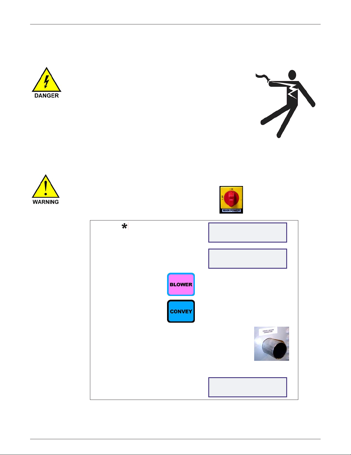
Confirm Correct Blower Rotation
On THREE PHASE units CONFIRM CORRECT BLOWER ROTATION by following these instructions:
Turn power on using main power switc h.
Press:
Display will say:
ENTER FIV E DI GI T
PASSWORD _ _ _ _ _
Press:
Press:
Press:
Place hand over the CONVEY VACUUM CONNECTION port
located on the right side of the Dryer. If there is VACUUM,
that indicates the c or r ec t rotation.
If air is blowing OUT, this is NOT correct.
Reverse any two power leads (not ground) to correct rotat ion.
Press:
22222
BLOWER
CONVEY
EXIT
Display will say:
Display will say:
TEMP=63°F v=0in
MODE=PROGRAM CAN=2
TEMP=63°F v=0in
MODE=AUTO CAN=2
14
Edition: Nov ember 5, 2010
LPD Dryer®
2.3 – Installin g th e Maguir e Re cei ver on a pr oc es s ma ch in e
If you intend to use the Maguir e Rec eiver to load your process
machine, foll ow these i nstr uc tions.
Attach the Magui re Receiver to the your process machine using the
four bolt holes located at the base of the Maguire Receiver.
Maguire Products, Inc.
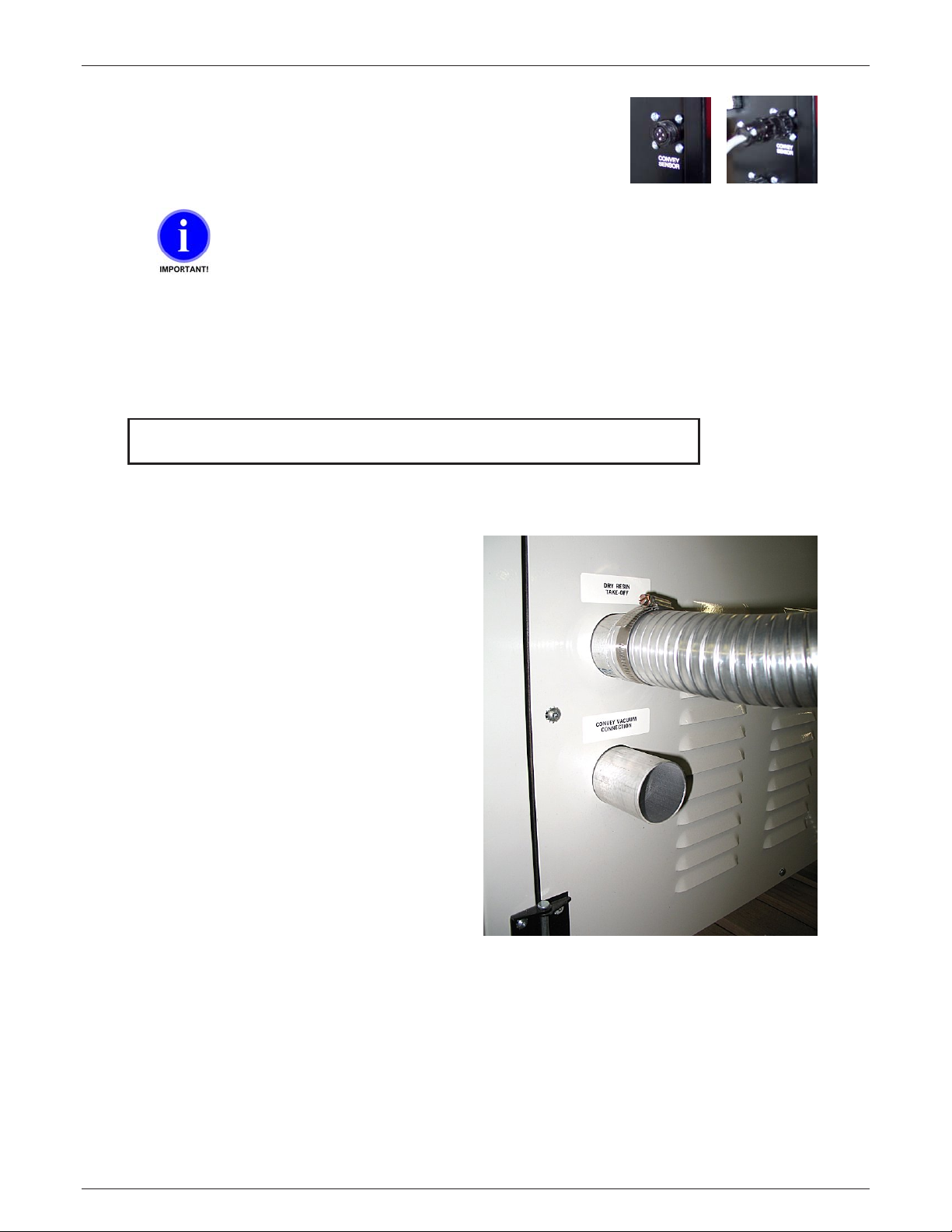
At the lower, right si de of t he Dryer ar e two ports. T he “Dry Resi n
Takeoff” port and the “ Convey Vacuum Connection” port. Using a hose
clamp, attach one end of the 2-inch vacuum line to the “Convey Vacuum
Connection” port.
Attach the other end of the 2-inch vacuum line to the port located on t op
of the Maguire Receiv er (vacuum), again using a hose clamp. Orient the
top port to face the right side of the Dryer by loosening the two clamps
and rotating it t o face the ri ght side if the Dryer for better access to the
“Convey Vacuum Connection” port.
Next, attach the mat eri al c onv ey line to the Maguire Receiver’s lower
port (materi al c onv ey ) using a hose clamp.
Next attach the ot her end of your Material Convey line to the “Dry Resin
Takeoff” port on the Dr y er .
Attach one end of the Convey Sensor Cable to the cable
port located at the base of the Maguire Receiver.
Edition: Nov ember 5, 2010
15
LPD Dryer®
Maguire Products, Inc.
Attach the other end of the Convey Sensor Cable to the
Convey Sensor port l oc ated on the left side of the Dryer’s
controller.
DO NOT wire tie the SENSOR cabl e to the MATERIAL hose. This will induce
static spik es i nto t he pr oc essor. Keep them separated.
2.4 – Using Your Own Receiver / Loa ding System on a proc es s ma ch in e
If you have installed our receiver: PROCEED TO: OPERATION
If you use your own Receiver / Loading
System:
Attach your Material Convey line to the “Dry
Resin Takeoff” port on the Dryer.
16
Edition: Nov ember 5, 2010

LPD Dryer®
2.5 - Using the Maguire Receiver to load the Dryer
If you have your own receiver/ lo ader: Proceed to the next section: OPERATION
If you intend to use the Maguire Rec eiver to load the Dryer, follow
these instructions.
Configuring the Dryer Sof tware t o u se M aguire Receiver to load
the Dryer
If you want to load the Dryer usi ng a Magui r e Rec eiv er see
the Star Functi ons section, page 42 and select the Convey Mode:
“CONVEY TO DRYER”.
Along with the Maguire Dryer, you will have been provided a Hopper
and a Hopper Lid, which incl udes a Hopper Lid Blank. The Hopper
Lid Blank will need to hav e the necessary mounting holes drilled into
it to mount the Maguir e Rec eiv er . Depending on the Maguire
Receiver you have, you will use one of two patterns to drill out the
necessary holes in t he Hopper Lid Blank. Note: The Hopper Lid
Blank can be supplied pr e- dr illed if requested. Patter ns are for
ADR-1 or ADR-4 and are located in this manual on page 119.
39 in
Maguire Products, Inc.
First remove t he two retaining screws from the Hopper Lid Blank, then using the appropriate
pattern, mark and dri ll the holes in the Hopper Lid Blank. Then re-attac h the Hopper Lid Blank to
the Hopper Lid.
Attach the Magui re Receiver to the Hopper
Lid before installing the Hopper Lid onto the
Hopper. Using the 4 bolthol es at the base of
the Receiver, install four ¼ inch bolts and
locknuts. See pi ctur e to t he ri ght.
After the Maguire Receiver has been attached
to the Hopper Lid, plac e the Hopper Lid on top
of the Hopper. Be sure to align t he exi sting
screw holes in the Hopper Lid with the screw
holes in the hopper. Secure the Hopper Lid to
the Hopper by installing 2 screws into the
screw holes. See pictur e to the right.
Edition: Nov ember 5, 2010
17
LPD Dryer®
At the lower, right si de of t he Dryer ar e two ports. T he “Dry Resi n
Takeoff” port and the “ Convey Vacuum Connection” port. Using a hose
clamp, attach one end of the 2-inch vacuum line to the “Convey Vacuum
Connection” port.
Attach the other end of the 2-inch vacuum line to the port located on t op
of the Maguire Receiv er (vacuum), again using a hose clamp. Orient the
top port to face the right side of the Dryer by loosening the two clamps
and rotating it t o face the ri ght side if the Dryer for better access to the
“Convey Vacuum Connection” port.
Maguire Products, Inc.
Next, attach the mat erial convey line to the
Maguire Receiver’s lower port (material
convey) using a hose clam p. The other end
of the material convey line will attach to
your material source such a s a Mat er ial
Pick-Up Lances as pictur ed to the right.
Attach one end of the Convey Sensor Cable to the cable
port located at the base of the Maguire Receiver.
Attach the other end of the Convey Sensor Cable to the
Convey Sensor port l oc ated on the left side of the Dryer’s
controller.
DO NOT wire tie the SENSOR cabl e to the MATERIAL hose. This will induce
static spik es i nto t he pr oc essor. Keep them separated.
18
Edition: Nov ember 5, 2010
LPD Dryer®
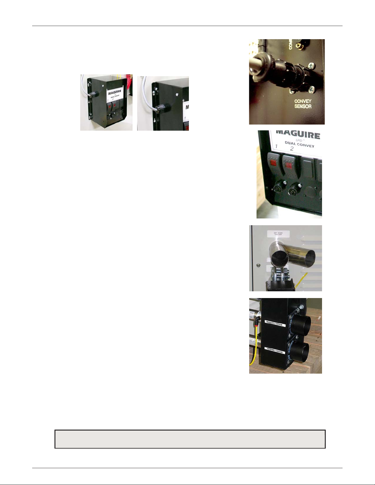
2.6 - Dual Convey Option
The Dual Convey Option all ows for one Dryer to supply material to two processes using two
Maguire Receivers. Using Dual convey requires the purchase of the Dual Convey Kit, which
includes:
• Dual Convey Receiv er Selector Control
• Dual Convey Solenoid
• Dual Convey Shifti ng Valve
• Y Resin Takeoff Pipe
• Nylon Air line
• NP T ¼” T fitting with Nylon Quick Connect
The following instr uc tions describe the installation of the Dual Convey Option on LPD 100 and
LPD 200 Series Dryers.
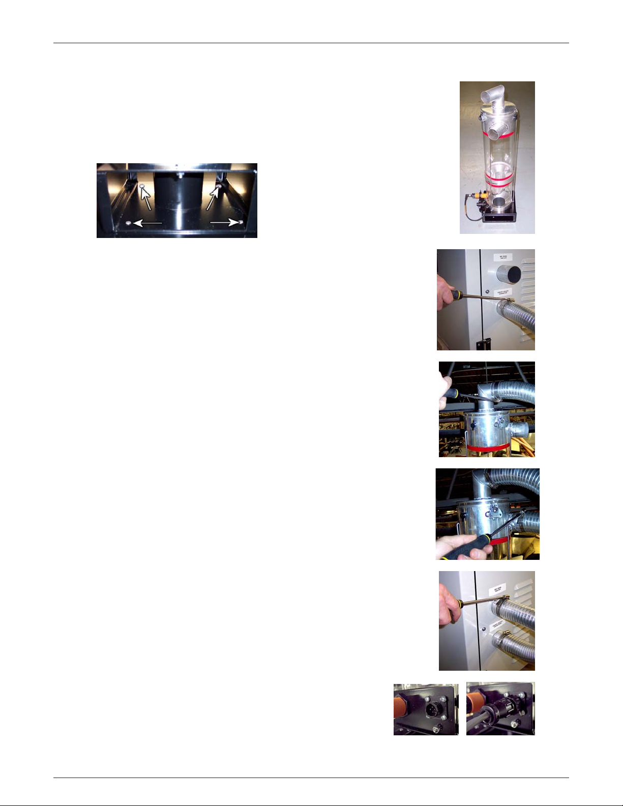
Maguire Products, Inc.
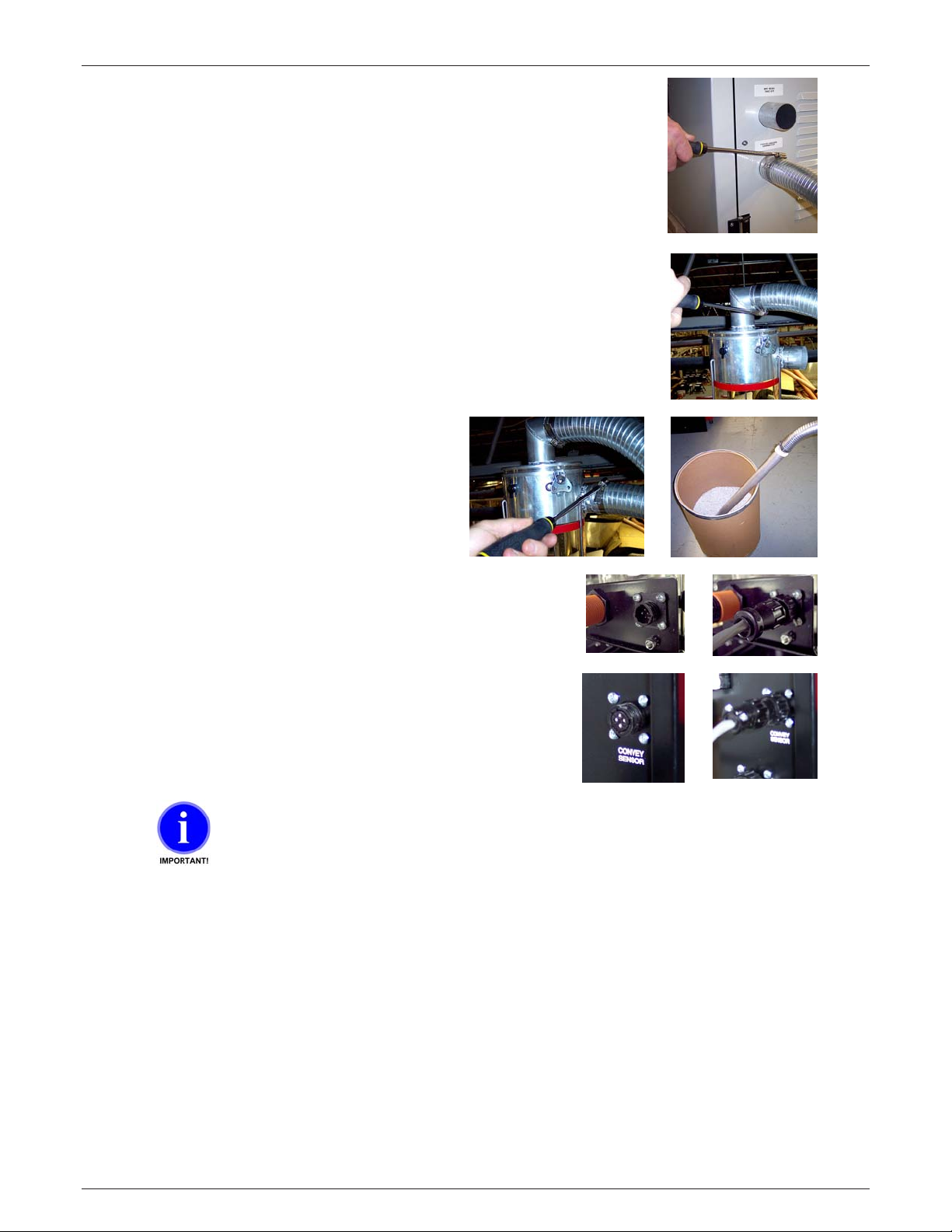
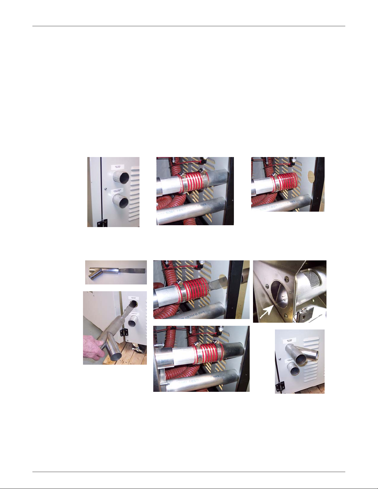
1. Open the front access door of the Dryer, loosen the hose clamp that secures the short
pipe labeled Dry Resi n Takeoff Pi pe ( top pipe). Remove the short stock pipe as shown
above.
2. Insert the “Y Resin Takeoff Pi pe” into the short connector hose and into the V ac uum
takeoff Assembl y (VT A ). Fitment may be tight, use a rubber mallet or block of wood to
gently tap the new “Y Resin Takeoff Pipe” into the Vacuum takeoff Assembly. The flange
of the Y Resin takeoff Pi pe shoul d c om e to t he end of the pipe wit hin the VTA.
CAUTION: Do Not stri k e a steel hammer directly on the Y Pipe as this may damage the
pipe.
Edition: Nov ember 5, 2010
19
LPD Dryer®
Maguire Products, Inc.
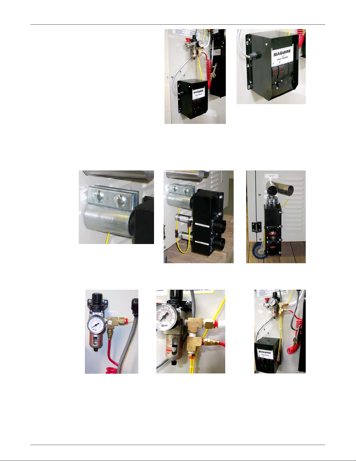
3.
Install the “Dual Conv ey
Receiver Selector Control
Box” below the air regulator.
You will have to drill four
holes in the panel of the
Dryer.
Caution: Remove the rear
panel of the dryer and
visually inspect to ensure
clearance befo re drilling
any holes in the cabinet
wall.
If you have been supplied a hole pattern, you may use the pattern, otherwise, center
punch the holes using the holes in the control box. Locati on of the up per left hole
should be approximately: On 200 Series Dryers - 2 inch in from the lef t edge of the
panel and 41 inches up fr om the bott om of t he panel. On 100 Series Dryers - 2 inch in
from the left edge of t he panel and 37 inc hes up fr om the bottom of t he panel.
4. Usi ng the supplied pipe clam p, secure the “Dual Convey Shifting V alv e” to the Convey
Vacuum Connection pipe located below the “Y” pipe (installed previously).
5. Remove the blowgun air hose from the ¼ inc h NPT “T ” fitti ng and install the new “T”
fitting as shown above. Re-install the blowgun facing out and t he Nyl on Quick Connect
facing down. Use Teflon thread tape to seal the threads. Connect a short lengt h of
nylon airli ne from the Nylon Quick Connect on the air supply down to the rear Nyl on
Quick Connect on the “Dual Convey Receiver Selector Control Box”. See image above
and image with Step 6.
20
Edition: Nov ember 5, 2010
LPD Dryer®
Maguire Products, Inc.
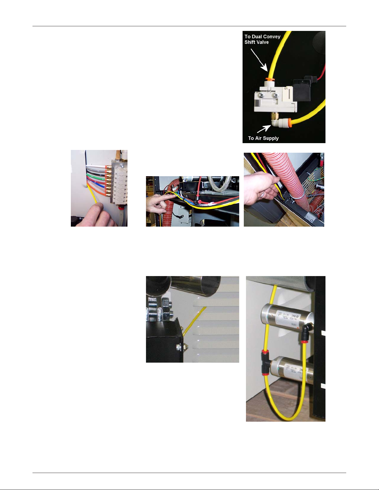
6. Route a nylon airline from t he top nylon quick
disconnect on the “D ual Convey Receiver Selector
Control Box” through the Dryer to the opposite side to
the “Dual Convey Shif ting Valve” as described below:
a. Insert on end of a long nylon airli ne in the front
nylon quick disconnect . This line will be run
though the Dryer. See im age to the right.
b. Route the nylon airli ne
up to the louver located to
the left of the air manifold
and run the line into the
lo uver.
e. Route the airline out
bottom louver to the “Dual
Convey Shifting Valve” as
pictured to the right.
f. Connect the nylon airl ine to the nylon quick disconnect on the
“Dual Convey Shifting Valve”. See image to the right.
c. With the back, upper panel
removed, rout e the airline along
with the existi ng air lines and
wires. Run the airline through
the existing wire loops to hold
the airline in place.
d. Route the airline down the
inside corner, through the
access hole. Route the
airline insi de the Dryer
towards the front and out t he
lower louver.
Edition: Nov ember 5, 2010
21
LPD Dryer®
Maguire Products, Inc.
7. Loc ated on the side of the “Dual Convey Receiv er Selector
Control Box” is a Conv ey Sensor cable. Connect that cable
to the Convey Sensor port located on the left side of the
Dryer’s controller.
8. Loc ated on the front of the “Dual Convey Receiver Selector
Control Box” is 2 ports for 2 Conv ey Sensor cables. A
Convey Sensor cable will run to each Maguire Receiver on
your process.
9. Run a m aterial convey line from each of the two outlets of
the Y tube at the Dry Resin takeoff por t to each of the two
Maguire Receivers on the process machines.
10. Run a Vac uum Convey Line from each of the Maguire
Receivers on the proc ess mac hines to the appropriate
Receiver Vacuum port on the Dual Convey Shifting Valve.
The assigned number (Rec eiver, Receiver 2) depends on
how you want to refer to and assign your rec eivers. Note:
Be sure that you run the BOTH the Convey S ensor cable
(for Receiver 1 and Receiver 2) and the Vacuum Convey
Lines to the same Receiver.
Usage: To supply material to a Maguire Receiver (Receiver 1, Receiver 2), turn the Receiver
Switch on the “Dual Conv ey Rec eiv er Sel ector Control Box” in the ON position. The “Dual
Convey Receiver S elec tor Control Box” will automatically supply material on demand t o the
Maguire Receivers.
PROCEED TO: OPERATION NEXT PAGE
22
Edition: Nov ember 5, 2010
LPD Dryer®
3 - Operation
3.1 - Standar d Operation
For a detailed descri ption of Dryer controls see “Controls Description” on page 29.
To help you identify your Dryer see: LPD Nomenclature / Order Code on page 90.
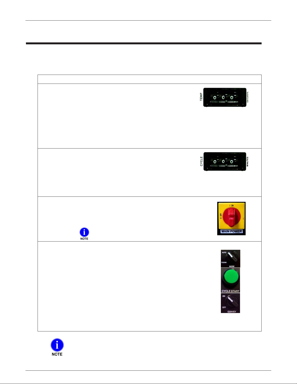
1. Fill the hopper on top of the dryer with material.
2. Set the TEMPERATURE - (TEMP thumbwheel switches)
USE THE SAME temperature setting recommended by the
resin manuf actur er for conventional desicc ant dry er s.
DO NOT exceed the manufactur er s recom m ended dr y ing temperature unl ess you are
sure the materi al will not soften and stick together.
Standard heat models can be set as high as 250 f (120c).
High heat models can be set to 300f (150c).
3. Set the CYCLE TIME - (CYCLE thumbwheel switc hes)
See RECOMMENDED CYCLE TIMES, next page.
These are suggested start ing points only. Run moisture t ests
to determine cor r ect c y cl e times, or submit your material to us for determinati on. See form on
page 87 for material testing.
Maguire Products, Inc.
4. OPERATOR STATION - Left Side
On the POWER box:
a. Turn MAIN POWER on. (RED switch)
On power up, the cani ster s will index to a starting
position based on the position when last shut down.
On the CONTROLLER:
b.
c.
d.
Turn MODE switch to AUTO.
Press CYCLE START.
Two timed cycles must be completed before material is
availabl e to be conv e y e d. When mat er ial is av ail a bl e, tur n
the CONVEY switch to the ON position (if applicable).
For a more indepth ex plaination of the operating sequence, please see Standard Operati ng
Sequence on page 25.
If you ever run material that does not require drying, set both Temperature and Cycle
time to 000. This keeps the heater off and allows indexing as required.
Edition: Nov ember 5, 2010
23

LPD Dryer®
DRYING TEMPERATURE***
3.2 – Recommended Cycle Times
MATERIAL
FINAL
MOISTURE % *
CYCLE TIME
(MINUTES)**
Maguire Products, Inc.
ºC ºF
ABS
ABS/PC
LCP
PA
PBT
PC
PC/PBT
PEEK
PEI
PES
PET (Mold ing Grade)
PET (Preform, Extrusion)
PMMA (Acrylic)
POM (Acetal)
PPO
PPS
PUR
PSU
SAN
* Final moisture c ontent as recommended by the raw material manufacturer.
** Recommended cycle time is based on average initial moisture content. For high initial
moisture cont ent cycle time should be extended 5 minutes. When in doubt contact Maguire
Service.
0.10 20 - 25 80 - 85 180 – 190
0.02 25 - 30 100 210
0.02 20 - 50 150 300
0.20 - 0.10 20 - 30 80 - 85 180 – 190
0.02 20 - 25 120 250
0.02 20 - 25 125 250
0.02 20 - 25 125 250
0.20 - 0.10 25 - 30 150 300
0.02 30 - 40 150 300
0.05 - 0.02 25 - 30 150 300
0.010 30 - 35 150 300
0.005 30 - 35 150 300
0.02 - 0.04 30 85 185
0.20 - 0.10 25 80 - 110 180 – 230
0.02 25 100 - 120 210 – 250
0.02 25 150 300
0.02 25 125 - 140 260 – 280
0.02 25 - 30 150 300
0.20 - 0.10 20 - 40 80 180
*** Drying temperature as recommended by the material manufacturer.
Drying is accomplished when all material reaches the proper temperature, and is then
placed under s u fficient vacuum for a suffici e nt per i od o f time.
Measurement of moisture content of material, both prior to and after drying, is
accomplished by using a moisture analyzer such as one manufactured by Arizona
Instruments.
If you are not obtaining the results you want or if you would like us to test your material
to determine the optimal drying cycle time, please see form on page 87 for material
testing.
24
Edition: Nov ember 5, 2010
LPD Dryer®
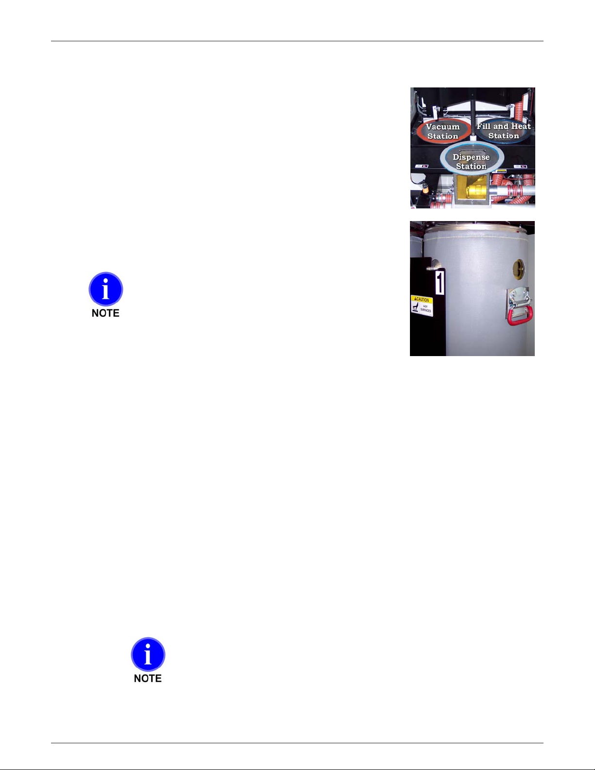
3.3 – Standard Operating Sequence
This section will help you understand what the dryer is doi ng as i t runs.
Inside the dryer encl osure are three identical m aterial cani ster s, whi c h
rotate through 3 st ations:
Fill and Heat Station (right rear)
•
Vacuum Station (left rear)
•
Dispense Station (front)
•
Each canister hangs i n one of t hr ee posi tions in the “Canister Hanger
Assembly”. These three posi tions are labeled 1,2 and 3. T he num ber
identifies the canisters position in t he assembly .
With the material in the hopper above the Fill and Heat station, press
CYCLE START to begin the sequence.
On power up, the cani ster s will index to a starting
position based on the position when last shut down.
"Operation" means the following actions occur:
1. The disks above and below each canister close.
2. The Blower turns on.
3. The vacuum generator turns on.
4. The air cylinder over the Disp ense Station extends to open the canister dispense valve located
inside the canister at the bottom, to deliver material to the process. If the bottom sensor was not
uncovered at the time of indexing, the fill valve will delay opening until the sensor becomes
uncovered.
5. The canister fill valv e ov er the Fill and Heat Station opens, filling the canister. A sensor located
under the Fill and Heat S t ation confirms the canister is in place before the fill valve will open.
6. The heater turns on.
7. With the opening of the Fill valve, the canister in the F ill and Heat Statio n begins to fill. Hot air
enters the canister to heat the material as it fills. The heati ng pr oc ess continues for the cycle time
set on the Cycle Time thumbwheel. At the same time, a vacuum is pulled on the canis ter in the
Vacuum Station.
8. After the cycle time elapses, the cycle ends and the canisters index count erclockwise to t he nex t
station. The heated material that was in the Fill and Heat Station has now moved to the
Vacuum Station. Here the vacuum dries the full charge of heated material.
The CYCLE TIMER only count s tim e when the heat ed air temper ature is within 20
degrees of target, and the vacuum has reached 25 inches. Therefor e, t he first
minute or so of each cycle does not count toward cycle time.
Maguire Products, Inc.
Edition: Nov ember 5, 2010
25

LPD Dryer®
9. After the cycle time elapses, the cycle ends and the canisters index counterclockwise again to the
next station. The dried m aterial that was in the Vacuum Station has now mov ed to t he
Dispense Station. Two cycles have passed and the dried material is ready for production.
From now on, indexing oc c ur s at the end of eac h cycl e time. This is the standard mode,
"advance on time". if you have sel ected the "advance when empty" opti on, then indexing occurs
only when the level sensor below the Di spense Station indi c ates the dispensing canister is
empty.
If you are using "advance when empty" option you have the ability to set a short fill time. If the time to use
the material in the canister is more then double the mini mu m cycle time set on the cycle time thu mbwheel,
we suggest you decrease the Fill time so that the canister does not hold so much material. Excessively long
cycle times may allow dried material to begin to re-absorb moisture.
Maguire Products, Inc.
3.4 – Operating Features/Options
Auto Start 22 - Allows for entry of a date/time to automatically start the dryer heating and vacuum cycle.
Aut o Stop
Material Alarm
Index Complete Alarm
Cycle Time Alarm
Convey Options
Convey Alarm
Advance Options Time/Empty
Dispense Valve Option s
Fill Valve Options
Hopper Fill Alarm
Key Functions - See the Keypad description of func tions on page 34 for more information.
See Star Functions on page 37 for more information.
24 - Allows for entry of a date/time to automatically stop the dry er heating and vacuum cycle.
See Star Functions on page 37 for more information.
33 - Alarm to alert an operator that dry material is ready to be conveyed after a cold start
of the dryer. See Star Functions on page 37 for more information.
34 – Alarm after every index and continue running. Thi s is int ended for lab
environment s where som eone has to m anually empty the canisters after each index. See Star
Functions on page 37 for mor e information.
36 – Alarm to alert an operat or that m aterial has run out before end of cycle.
39 – Material convey options are “Standard Convey”, “Convey and Purge” and “Convey
to Dryer”. See Star Functions on page 37 for more informati on.
40 - After initial fill ing of the Maguire receiver, the dryer will alarm if the Maguire receiver
conveying mat erial to your process does not fill on the 3rd attempt. See Star Functions on page
37 for more information.
44 - "Advance on Time" will adv anc e the canisters (index) when the cycl e timer
times out, even if canister is not empty. "Advance on Empty" will advance only after the canister
is empty. See Star Functi ons on page 37 for more information.
52 - Options for dispensing the front canister. Choose between “Enabled”, “Disabl ed”
and “Pulsed”. Enabled for normal operation, disable will not dispense, and pulsed will pulse the
dispense valve on and off when dispensing. See Star Functions on page 37 for more information.
53 - Options for filli ng the canister. Choose between “Enabled” and “D isabled”.
Enabled for normal operation, disable will not fill the canister automatically. See Star Functions on
page 37 for more information.
74 - When enabled, the Dryer alarms if the Hopper fails to fill withi n the time specified.
See Star Functions on page 37 for more information.
Empty key - Manually opens the bott om v alv e at t he “Dispense Station” to empty a canister.
Fill key - Manually opens the fill valve, above the “FILL and HEAT stati on”.
Convey Key – Manuall y shif t hot air flow v alv es to c onv ey mat eri al.
26
Edition: Nov ember 5, 2010

LPD Dryer®
Maguire Products, Inc.
3.4.1 – Convey-Only Mode
In this convey-only mode, the LPD dos not heat, pressurize, fill, or index. This mode will only
convey material to a Maguire ADR (Maguire Dryer Receiver).
To use this mode:
Remove the material hose from the dryer and insert into a container of material. A material
lance is recommended.
Set the temperature thumbwheel set to 000
Set the time thumbwheel to 999
Set the Convey Switch to ON.
Pressing the start button will activate this mode.
Press and hold the “Set Convey Time” button to set the convey time. When conveying starts,
immediately press the "convey time" button and hold until the desired level in the receiver is
reached; then release. This load time will be saved by the software.
Once started, the LPD will only process convey requests from the convey signal/sensor on the
ADR.
Exit convey-only mode, press the STOP button and reset the thumbwheels.
Auto-start and auto-stop functions will work, as well as pausing the mode by opening the door
(closing the door resumes where it left off).
If no convey signal is seen for 10 minutes the blower is turned off. The blower will be turned
back on before starting the next convey request.
Edition: Nov ember 5, 2010
27

LPD Dryer®
cycle. Canisters always wait until the canisters are empty, sensor uncovered.
3.5 – Changin g Col or s “On T he Fl y” U sin g th e Clean Mode
Canisters and surrounding parts may be hot. Use of gloves
is recommended.
To CHANGE COLORS without stopping production:
PLAN AHEAD!
If your canister s are f ull, you have at least ONE hour of material in the pipe li ne. So, you must plan far
enough ahead to allow time to consume this material. So....
ONE hour before the change is required:
1. S et the MODE switch to "CLEAN". In this mode, canisters DO NOT INDEX automatically.
2. S hut off your feed system and clean t he dr y er hopper and t he r ec eiver or blender supplying
material. Be sure to clear the fill valve area under the dryer hopper. The fill v alv e is accessible
and removable by r em ovi ng one bolt f r om the hopper base and rotating the hopper out of
position.
Perform a full clean out and colo r change up to this point, the fill point above the canister.
See section 4.13, Canister Removal / Cleaning on page 66 under the Maintenance and
Service section.
In the CLEAN mode CANISTERS DO NOT INDEX at the end of the cycle. The ALARM sounds
and the display says ( CLEAN ).
When the ALARM sounds:
1. P r ess "Al arm Silence" to preserve your sanity.
2. Remove, clean, and repl ac e the cani ster ; close door.
3. P r ess the INDE X button.
4. After Indexing occurs, begin the filling of the newly cleaned cani st er with the new color blend.
Repeat these 4 steps as each of the remaining canisters empt y.
After the final canister is cleaned:
1. Clear the conveying line t o the proc ess m ac hine.
2. B egin conveying the new color blend to the process.
In the CLEAN mode, canister s do not advance on the time out of the TIME
Maguire Products, Inc.
If the time exceeds double t he normal cycle time, the alarm will sound. Either
silence, or press advance if you are concerned that material may be picking
up moisture.
28
Edition: Nov ember 5, 2010
LPD Dryer®
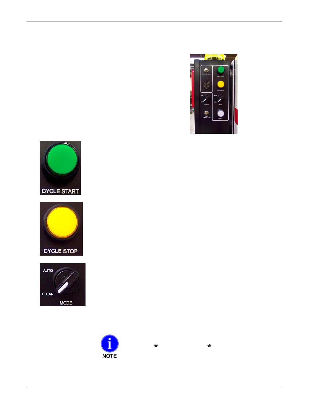
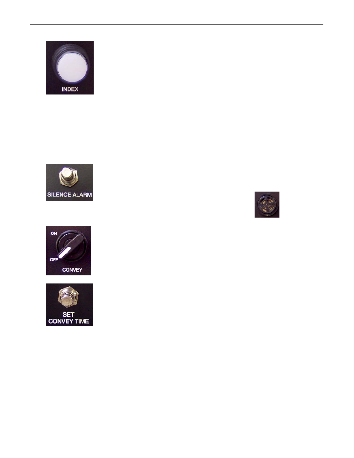
3.6 – Controls Description
3.6.1 – Controller & Operator Station
Controller - Right Side
• CYCLE START
• CYCLE STOP
• MODE
• INDEX
• SILENCE ALAR M
• CONVEY: ON /OFF
• SET CONVEY TIME
CYCLE START
Press to START the cycle.
Lights when the unit is running automatically.
Maguire Products, Inc.
CYCLE STOP
Press to STOP the cycle.
Lights when the unit has been stopped by t he oper ator or has stopped
between cycles in the "clean out" mode.
MODE - AUTO / CLEAN
Select AUTO for norm al automatic indexing of canisters.
Select CLEAN to PREVENT AUTOMATIC INDEXING.
This is for COLOR CHANGES. INDEXING will NOT occur
automatic all y . Instead the A LA RM wil l sound, and the operator
knows to CLEAN OUT the empty cani ster for the next color.
With a CLEANED CANISTER in place, the door is closed and the
INDEX button is pressed to restart the cycle.
When in Clean Mode, the cycle will continue until the
time set in
information. Star Functions begin on page 37.
Edition: Nov ember 5, 2010
37 has elapsed. See 37 for more
29
LPD Dryer®
Maguire Products, Inc.
INDEX
Press to MANUALLY ADVANCE the canisters (with Dryer stopped).
In the CLEAN mode,
you must press the INDEX button t o adv anc e the canisters. The next
cycle starts as soon as INDEXING is complete.
In the AUTO mode,
the index button does not work unless you press CYCLE
STOP first. INDEX then serv es to m anually advance the canisters. After
INDEXING, press CYCLE START to start the next cycle.
When blinking in combination with the GREEN Cycle Start Button:
Cycle has stopped in t he "clean" mode, the operator must press the
INDEX button to advanc e the canisters after cleaning.
SILENCE ALARM
This button sil enc es the STROBE and BEEPER ALARMS, but does not
remedy the cause of t he alarm.
ALARM SPEAKER
CONVEY: ON/OF F
Operates only if a Maguir e v ac uum receiver is connected to the Dryer
controls. Turn ON to enable conveying of dried material to your process
machine.
SET CONVEY TIME
Operates only if we provi de a v ac uum receiver connected to the dryer
controls. Press and hold to set the convey time. When conveying star ts,
immediately pr ess the "convey time" button and hold until the desi r ed
level in the receiver is reached; then release. This load time will be
saved by the software. The minimum possible time, as well as initi al
default setti ng, is two seconds.
30
Edition: Nov ember 5, 2010
 Loading...