

Magtrol HD-505, HD-700, HD-500, HD-705, HD-710 User Manual
...
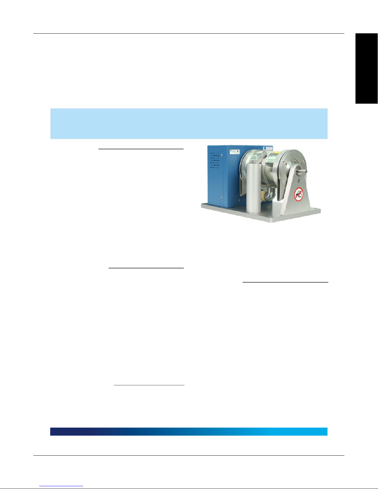
HD and ED Series
Hysteresis Dynamometers
User’s Manual

Purchase Record
Please record all model numbers and serial numbers of your
Magtrol equipment, along with the general purchase information.
The model number and serial number can be found on either
a silver identification plate or white label affixed to each unit.
Refer to these numbers whenever you communicate with a
Magtrol representative about this equipment.
Model Number: _____________________________
Serial Number: _____________________________
Purchase Date: _____________________________
Purchased From: _____________________________
While every precaution has been exercised in the compilation of this document to ensure
the accuracy of its contents, Magtrol, Inc./Magtrol SA assumes no responsibility for
errors or omissions. Additionally, no liability is assumed for any damages that may result
from the use of the information contained within this publication.
COPYRIGHT
Copyright ©2002-2018 Magtrol, Inc. All rights reserved.
Copying or reproduction of all or any part of the contents of this manual without the
express permission of Magtrol is strictly prohibited.
TRADEMARKS
LabVIEW™ is a trademark of National Instruments Corporation.
Microsoft® is a registered trademark of Microsoft Corporation.
National Instruments™ is a trademark of National Instruments Corporation.
Windows® is a registered trademark of Microsoft Corporation.
4th Edition, revision O – May 2018
CAUTION
BRAKE SURFACES MAY BECOME HOT
CAUTION
LIFTING BY BRAKE ASSEMBLY
MAY CAUSE DAMAGE TO
TORQUE SENSOR
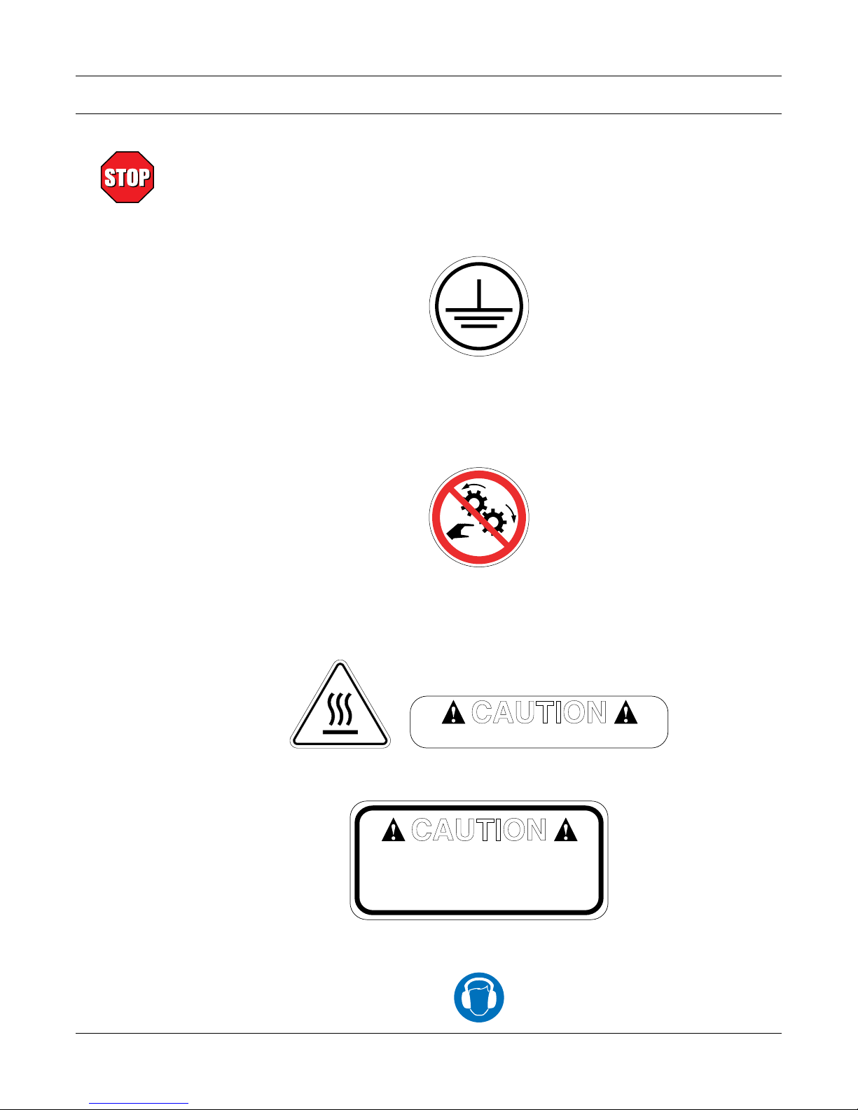
Safety Precautions
Several warning labels are affixed directly to the dynamometer. These warnings are discussed in
further detail below. Please take the time to read this page thoroughly before connecting and using
your dynamometer.
1. Make sure that all Magtrol dynamometers and electronic products are earth-grounded, to ensure
personal safety and proper operation.
2. Check line voltage before operation on any dynamometer that uses AC input power.
3. Make sure that dynamometers are equipped with a protective cover to prevent contact with the
rotating shaft and coupling. The protective cover must be equipped with a safety interlock to
disable the test motor if the cover is removed.
4. Make sure that all motors under test are equipped with appropriate safety guards.
5. Use caution with exposed brake surfaces. They have a tendency to become very hot during long
periods of operation.
6. Do not lift the unit by the brake assembly, as it may cause damage to the torque sensor.
7. When operating dynamometers with blowers, hearing protection must be worn.
i

Revisions To This Manual
The contents of this manual are subject to change without prior notice. Should revisions be necessary, updates to all
Magtrol User’s Manuals can be found at Magtrol’s web site at www.magtrol.com/support/manuals.htm.
Please compare the date of this manual with the revision date on the web site, then refer to the manual’s Table of
Revisions for any changes/updates that have been made since this edition.
REVISION DATE
4th Edition, revision O – May 2018
TABLE OF REVISIONS
Date Edition Change Section(s)
05/22/18 4th Edition - rev. O
02/18/16 4th Edition - rev. N
06/11/15 4th Edition - rev. M
05/11/15 4th Edition - rev. L Compressed air regulator setting changed for HD-800 dynamometer. 1.3, 4.1.3.2.1
09/04/14 4th Edition - rev. K Updated description of booster power amplier. 5.6.1
06/09/14 4th Edition - rev. J
02/26/14 4th Edition - rev. I All referneces to DSP6001 changed to DSP7000 throughout manual
06/01/12 4th Edition - rev. H
05/21/12 4th Edition - rev. G
10/07/08 4th Edition - rev. F Temperature conditions for maximum power absorption 4.1.3.1
08/31/07 4th Edition - rev. E Updated electrical power and fuse ratings 1.3
08/31/07 4th Edition - rev. E New resistance and current values for HD-106 8.1.3.1, 8.1.3.2
08/31/07 4th Edition - rev. E Added note about circuitry between connector and brake coil 8.1.3.1
06/11/07 4th Edition - rev. D Deleted: Analog Outputs 7.2, 1.3
03/12/07 4th Edition - rev. C Updated calibration drawings and procedure 6.4
03/12/07 4th Edition - rev. C Added new section: "Calibration Beams and Weights" 6.2
02/02/07 4th Edition - rev. B New "A", "P" and "Q" dimensions for HD-700 series dynamometers 1.3
02/02/07 4th Edition - rev. B Change in torque, speed and power ratings. 1.3, 4.1.3.1
06/28/06 4th Edition - rev. A Change in power and speed ratings for HD-805. 1.3, 4.1.3.1
01/23/06 4th Edition All HD and ED data sheets condensed to one single data sheet. 1.3
01/23/06 4th Edition HD-515 (compressed air cooled) dynamometer added to product line.
01/23/06 4th Edition New resistance and current values for HD-500 and HD-505 8.1.3.1, 8.1.3.2
10/12/05 3rd Edition - rev. D Note to "call factory" for HD-805 power and speed ratings 1.3.3, 4.1.3.1
10/12/05 3rd Edition - rev. D Change in power rating (5 minutes) for HD-800 1.3.3, 4.1.3.1
02/24/05 3rd Edition - rev.C Hearing safety warnings added
12/09/04 3rd Edition - rev.B Electrical power and fuse ratings added to data sheets 1.3.1–1.3.4
03/11/04 3rd Edition - rev. A
12/08/03 3rd Edition HSD Series High Speed Dynamometers discontinued throughout manual
10/27/03 2nd Edition - rev. E Change in maximum torque rating for HSD-710-8N 1.3.5, 4.1.3.1
6510e/6530 Power Analyzer references changed to 7500 Series
Power Analyzer.
HD-805 Dynamometer regulator setting updated for maximum air ow
cooling.
Speed sensor board schematic added for 2015 and later
dynamometers.
Note added concerning operation at continuous power rating for long
intervals and high temperatures.
Dimensions were updated on the data sheet for the HD-800 and HD810 model dynamometers
Part number for the 88M007 and 88M070 cables was changed to
88M007-0150 and 88M070-0150
5410 Torque/Speed Readout and 5200/5210 Power Supply removed
from manual/open-loop test system congurations
throughout manual
4.1.3.2.1
B.2
4.3.1
1.3
1.3, 3.3.1, 3.3.2
1.3, 2.2, 3.3.3,
3.3.3.2, 4.1.3.1,
4.1.3.2.1, 8.1.3.1,
8.1.3.2
2.2, 3.3.3.1, 4.1.1,
4.1.3.2.2
1.3.1–1.3.4, 3.3.1
ii

10/27/03 2nd Edition - rev. E Added short base plate option 1.3.1–1.3.3
10/27/03 2nd Edition - rev. E Change in speed encoder options 1.3.1–1.3.4
10/02/03 2nd Edition - rev. D New dimensions for HD-700 series dynamometers 1.3.2
09/25/03 2nd Edition - rev. C New "B" dimension for HD-400 1.3.1
09/25/03 2nd Edition - rev. C New "B" and "E" dimensions for HD-106 1.3.1
08/19/03 2nd Edition - rev. B New schematic drawing for HD-800–815 Brake Control Supply B.4
03/17/03 2nd Edition - rev. A New "F" dimension for HSD-610M 1.3.5
03/17/03 2nd Edition - rev. A New Dynamometer Table added to System Options and Accessories 1.3.1–1.3.5
01/03/03 2nd Edition
Added more information about air cooling – air ow sensor now
standard
3.3.3
01/03/03 2nd Edition Inserted new chapter about optional features chapter 7
01/03/03 2nd Edition HSD High Speed Dynamometer information added throughout manual
iii

Table of Contents
SAFETY PRECAUTIONS .........................................................................................................................I
REVISIONS TO THIS MANUAL ...............................................................................................................II
TABLE OF CONTENTS ......................................................................................................................... IV
TABLE OF FIGURES ........................................................................................................................................................ VI
PREFACE ............................................................................................................................................... VI
PURPOSE OF THIS MANUAL ........................................................................................................................................VI
WHO SHOULD USE THIS MANUAL .............................................................................................................................VI
MANUAL ORGANIZATION ............................................................................................................................................ VI
CONVENTIONS USED IN THIS MANUAL ..................................................................................................................VII
1. INTRODUCTION ................................................................................................................................1
1.1 UNPACKING YOUR HYSTERESIS DYNAMOMETER ...........................................................................................1
1.2 FEATURES OF THE HYSTERESIS DYNAMOMETER ............................................................................................ 2
1.2.1 HD SERIES ..................................................................................................................................................... 2
1.2.2 ED SERIES ..................................................................................................................................................... 2
1.3 DATA SHEET ................................................................................................................................................................ 3
2. INPUTS/OUTPUTS ...........................................................................................................................16
2.1 REAR PANEL ............................................................................................................................................................. 16
2.2 REAR PANEL INPUTS AND OUTPUTS.................................................................................................................. 16
3. INSTALLATION/CONFIGURATION ..................................................................................................18
3.1 REMOVAL OF THE LOAD CELL SHIPPING/RESTRAINING BOLT .................................................................. 18
3.1.1 HD-100, -400 AND -500 SERIES ................................................................................................................ 18
3.1.2 HD-700 SERIES ........................................................................................................................................... 19
3.1.3 HD-800 SERIES ........................................................................................................................................... 19
3.1.4 ED-715 .......................................................................................................................................................... 19
3.1.5 ED-815 .......................................................................................................................................................... 19
3.2 EARTH GROUND ...................................................................................................................................................... 20
3.3 SYSTEM CONFIGURATIONS ..................................................................................................................................21
3.3.1 MANUAL TEST SYSTEMS ........................................................................................................................ 21
3.3.2 PC-BASED TEST SYSTEMS ...................................................................................................................... 22
3.3.3 AIR COOLING ............................................................................................................................................. 23
4. TESTING ...........................................................................................................................................25
4.1 TESTING CONSIDERATIONS .................................................................................................................................25
4.1.1 SAFETY ........................................................................................................................................................ 25
4.1.2 ACCURACY ................................................................................................................................................. 25
4.1.3 POWER DISSIPATION ................................................................................................................................ 26
4.1.4 FIXTURES AND COUPLINGS ................................................................................................................... 38
4.1.5 WINDAGE .................................................................................................................................................... 38
4.1.6 FRICTION .................................................................................................................................................... 39
4.1.7 VIBRATION ................................................................................................................................................. 39
4.1.8 COGGING .................................................................................................................................................... 40
4.1.9 EDDY CURRENTS ...................................................................................................................................... 40
iv

Magtrol Hysteresis Dynamometers
4.1.10 TEMPERATURE RISE ................................................................................................................................ 41
Table of Contents
5. OPERATING PRINCIPLES ...............................................................................................................42
5.1 SPEED ......................................................................................................................................................................... 42
5.2 TORQUE ..................................................................................................................................................................... 42
5.3 TORQUE SIGNAL AMPLIFICATION ...................................................................................................................... 43
5.4 DECIMAL POINT CONTROL .................................................................................................................................. 43
5.5 DAMPER CYLINDER ............................................................................................................................................... 44
5.6 BRAKE CONTROL POWER ..................................................................................................................................... 44
5.6.1 HD-800/815 AND ED-815 ........................................................................................................................... 44
5.6.2 HD-825 .......................................................................................................................................................... 44
6. CALIBRATION ..................................................................................................................................45
6.1 INITIAL CALIBRATION ........................................................................................................................................... 45
6.2 CALIBRATION BEAMS AND WEIGHTS ............................................................................................................... 45
6.3 CALIBRATION PREPARATION ............................................................................................................................... 46
6.4 CALIBRATION PROCEDURE .................................................................................................................................. 46
6.5 CALIBRATION FREQUENCY.................................................................................................................................. 48
7. OPTIONAL FEATURES ....................................................................................................................49
7.1 SPEED ENCODER ..................................................................................................................................................... 49
8. TROUBLESHOOTING .......................................................................................................................50
8.1 TORQUE READOUT PROBLEMS ........................................................................................................................... 50
8.1.1 NEW DYNAMOMETER ............................................................................................................................. 50
8.1.2 ZERO BALANCE ......................................................................................................................................... 50
8.1.3 FULL SCALE TORQUE .............................................................................................................................. 51
8.1.4 MECHANICAL (ROTATIONAL) ALIGNMENT ....................................................................................... 53
8.2 SPEED READOUT PROBLEMS ............................................................................................................................... 54
APPENDIX A: CALIBRATION RECORD .............................................................................................55
APPENDIX B: SCHEMATICS ...............................................................................................................56
B.1 TORQUE AMPLIFICATION BOARD ....................................................................................................................... 56
B.2 SPEED SENSOR BOARD ......................................................................................................................................... 57
B.3 LOAD CELL SCHEMATIC........................................................................................................................................ 58
B.4 HD-800–815 BRAKE CONTROL SUPPLY .............................................................................................................. 59
B.5 HD-825 BRAKE CONTROL SUPPLY ...................................................................................................................... 60
INDEX .....................................................................................................................................................61
SERVICE INFORMATION ......................................................................................................................63
RETURNING MAGTROL EQUIPMENT FOR REPAIR AND/OR CALIBRATION ..................................................... 63
RETURNING EQUIPMENT TO MAGTROL, INC. (UNITED STATES) ................................................................ 63
RETURNING EQUIPMENT TO MAGTROL SA (SWITZERLAND) ..................................................................... 63
v

Magtrol Hysteresis DynamometersTable of Contents
TABLE OF FIGURES
2. INPUTS/OUTPUTS
Figure 2–1 Rear Panel ..............................................................................................................................................16
Figure 2–2 Dynamometer Brake Input .....................................................................................................................16
Figure 2–3 Dynamometer Connector .......................................................................................................................16
Figure 2–4 Calibration Potentiometers.....................................................................................................................17
Figure 2–5 Speed Encoder Switch ............................................................................................................................17
Figure 2–6 Blower Input ...........................................................................................................................................17
Figure 2–7 Compressed Air Input .............................................................................................................................17
3. INSTALLATION/CONFIGURATION
Figure 3–1 HD 100–500 Series Shipping/Restraining Bolt Location .......................................................................18
Figure 3–2 HD-700 Series Shipping/Restraining Bolt Location ..............................................................................19
Figure 3–3 ED-715 Shipping/Restraining Bolt Location .........................................................................................19
Figure 3–4 HD 100–500 Series Top View ................................................................................................................20
Figure 3–5 HD-800 Series Top View .........................................................................................................................20
Figure 3–6 Dynamometer with 6200 Controller .......................................................................................................21
Figure 3–7 Dynamometer with DSP7001 Controller and M-TEST Software ...........................................................22
Figure 3–8 Dynamometer with 6510e Power Analyzer, DSP7001 Controller and M-TEST Software .....................22
Figure 3–9 Air Flow Sensor Schematic ....................................................................................................................23
Figure 3–10 Dynamometer with Blower Connection ...............................................................................................24
Figure 3–11 Dynamometer with Compressed Air Connection .................................................................................24
4. TESTING
Figure 4–1 Power Absorption Curve Parameters .....................................................................................................27
Figure 4–2 HD 106 Power Absorption Curve ...........................................................................................................28
Figure 4–3 HD 100 Power Absorption Curve ...........................................................................................................28
Figure 4–4 HD 400 Power Absorption Curve ...........................................................................................................29
Figure 4–5 HD 500 Power Absorption Curve ..........................................................................................................29
Figure 4–6 HD 510 Power Absorption Curve ...........................................................................................................30
Figure 4–7 HD 505 Power Absorption Curve ...........................................................................................................30
Figure 4–8 HD 515 Power Absorption Curve ...........................................................................................................31
Figure 4–9 HD 700 Power Absorption Curve ...........................................................................................................31
Figure 4–10 HD 710 Power Absorption Curve .........................................................................................................32
Figure 4–11 HD 705 Power Absorption Curve .........................................................................................................32
Figure 4–12 HD 715 Power Absorption Curve .........................................................................................................33
Figure 4–13 HD 800 Power Absorption Curve .........................................................................................................33
Figure 4–14 HD 810 Power Absorption Curve .........................................................................................................34
Figure 4–15 HD 805 Power Absorption Curve .........................................................................................................34
Figure 4–16 HD 815 Power Absorption Curve .........................................................................................................35
Figure 4–17 HD 825 Power Absorption Curve .........................................................................................................35
Figure 4–18 ED 715 Power Absorption Curve .........................................................................................................36
Figure 4–19 ED 815 Power Absorption Curve .........................................................................................................36
Figure 4–20 Dynamometer with Compressed Air Connection .................................................................................37
Figure 4–21 Dynamometer with Blower Connection ...............................................................................................37
Figure 4–22 Examples of Possible Shaft Misalignment ............................................................................................38
Figure 4–23 Hysteresis Brake Cross-Section ............................................................................................................40
5. OPERATING PRINCIPLES
Figure 5–1 Mechanical Layout of a Load Cell .........................................................................................................42
6. CALIBRATION
Figure 6–1 Calibration Label ...................................................................................................................................45
Figure 6–2 Calibration Setup ...................................................................................................................................46
Figure 6–3 Calibration Potentiometers.....................................................................................................................47
Figure 6–4 Calibration Calculation .........................................................................................................................47
7. OPTIONAL FEATURES
Figure 7–1 Speed Encoder Schematic.......................................................................................................................49
8. TROUBLESHOOTING
Figure 8–1 Damper Connection ...............................................................................................................................53
vi

PURPOSE OF THIS MANUAL
This manual contains all the information required for the setup and general use of Magtrol’s Hysteresis
Dynamometers. To achieve maximum capability and ensure proper use of the dynamometer, please
read this manual in its entirety before operating. Keep the manual in a safe place for quick reference
whenever a question should arise.
WHO SHOULD USE THIS MANUAL
This manual is intended for those operators who are planning to use any of Magtrol’s Hysteresis
Dynamometers.
MANUAL ORGANIZATION
This section gives an overview of the structure of the manual and the information contained within it.
Some information has been deliberately repeated in different sections of the document to minimize
cross-referencing and to facilitate understanding through reiteration.
The structure of the manual is as follows:
Chapter 1: INTRODUCTION – Contains the technical data sheets for Magtrol’s Hysteresis
Dynamometers, which describe the units and provide detailed technical
characteristics.
Preface
Chapter 2: INPUTS/OUTPUTS – Description of the elements located on the rear panel of the
dynamometer.
Chapter 3: INSTALLATION/CONFIGURATION – Provides information needed for setup of
the dynamometer. This includes load cell shipping/restraining bolt removal, earth
ground instruction and configurations for manual, computer-controlled and aircooled test setups.
Chapter 4: TESTING – Provides information on how to run a test along with considerations
that should be taken when operating the dynamometer.
Chapter 5: OPERATING PRINCIPLES – Information pertaining to theory of operation including
speed, torque, torque signal amplification, decimal point control, damper cylinder
and brake control power.
Chapter 6: CALIBRATION – Provides recommended calibration schedules along with step-
by-step instructions for the calibration procedure.
Chapter 7: OPTIONAL FEATURES – Provides information regarding various optional features
available to enhance the capability of Magtrol’s Hysteresis Dynamometers including
speed encoders and analog outputs.
Chapter 8: TROUBLESHOOTING – Solutions to common problems encountered during setup
and testing.
Appendix A: CALIBRATION RECORD – Data sheet for tracking calibration results.
Appendix B: SCHEMATICS – For the torque amplification board, speed sensor board, load cell
and brake control power supplies.
vi

Magtrol Hysteresis Dynamometers
CONVENTIONS USED IN THIS MANUAL
The following symbols and type styles may be used in this manual to highlight certain parts of the
text:
Preface
Note: This is intended to draw the operator’s attention to complementary
information or advice relating to the subject being treated. It
introduces information enabling the correct and optimal function
of the product.
Caution: this is used to draw the operator’s attention to information,
direCtives, proCedures, etC. whiCh, if ignored, may result in damage
to the material being used. the assoCiated text desCribes the
neCessary preCautions to take and the ConsequenCes that may
arise if these preCautions are ignored.
WARNING! THIS INTRODUCES DIRECTIVES, PROCEDURES,
PRECAUTIONARY MEASURES, ETC. WHICH MUST
BE EXECUTED OR FOLLOWED WITH THE UTMOST
CARE AND ATTENTION, OTHERWISE THE PERSONAL
SAFETY OF THE OPERATOR OR THIRD PARTY MAY
BE AT RISK. THE READER MUST ABSOLUTELY
TAKE NOTE OF THE ACCOMPANYING TEXT, AND
ACT UPON IT, BEFORE PROCEEDING FURTHER.
WHEN HEARING PROTECTION IS REQUIRED, THE STOP
SIGN IS REPLACED WITH THE EAR MUFF SYMBOL.
vii

1. Introduction
1.1 UNPACKING YOUR HYSTERESIS DYNAMOMETER
Your Hysteresis Dynamometer was packaged in reusable, shock resistant packing material that will
protect the instrument during normal handling.
1. Make sure the carton contains the following:
INFORMATION
GENERAL
Magtrol User Manual CD-Rom
Hysteresis Dynamometer
2. Inspect the contents for any evidence of damage in shipping. In the event of shipping damage,
immediately notify the carrier and Magtrol’s Customer Service Department.
Note: Save all shipping cartons and packaging material for reuse when
returning the instrument for calibration or servicing.
3. Remove the Shipping Bolt
Before proceeding any further, you will need to remove the load cell shipping/restraining
bolt if you have just unpacked a new:
PLEASE TAKE NOTICE!
Line Cord
(not included with 700
series or HD-825)
Brake Cable14-Pin Instrument Cable
Calibration Certificate
HD-100 HD-500 HD-515 HD-710
HD-106 HD-505 HD-700 HD-715
HD-400 HD-510 HD-705 ED-715
This does not apply to HD-800, HD-805, HD-810, HD-815, HD-825 or ED-815
Dynamometers. For further instruction see Section 3.1 Removal of the Load Cell
Shipping/Restraining Bolt.
Note: Retain the shipping/restraining bolt for future use when
moving or shipping your Magtrol Dynamometer.
8

Magtrol Hysteresis Dynamometers
Chapter 1 – Introduction
1.2 FEATURES OF THE HYSTERESIS DYNAMOMETER
All Magtrol Hysteresis Dynamometers (HD and ED Series) feature the following:
• Hysteresis Braking System: The dynamometers do not require speed to create torque, and
therefore can provide a full motor ramp from free-run to locked rotor along with precise
torque loading.
• Air Flow Sensor: Any Magtrol Hysteresis Dynamometer that is internally ported for
compressed air and/or blower cooling contains an air flow sensor that provides protection
against overheating and operator error
• Standard Torque Units: English, metric and SI are available.
• Easy Calibration
Unique features of each series are listed below.
1.2.1 HD SerieS
Magtrol’s HD Series Dynamometers are versatile and ideal for testing in low to medium power
ranges. Features include:
• Accuracy: ±0.25% to ±0.5% full scale, depending on size and system configuration.
• Custom Dynamometers: For special torque and speed requirements.
• Encoder Switch: Optional feature that allows the user to switch between a 60 and 600-bit
encoder or a 60 and 6000-bit encoder.
INFORMATION
GENERAL
1.2.2 eD SerieS
Magtrol’s ED Series Dynamometers are high performance dynamometers specifically designed to
address the severe, high vibration conditions inherent in internal combustion engine testing. Features
include:
• Accuracy: ±0.25% full scale.
• High Speed Capabilities: 12,000 to 25,000 rpm, depending on model.
• Rugged Stainless Steel Shaft: Larger shaft for additional strength.
• Specially Reinforced Load Cell: Stainless steel pin used at contact point to prevent
premature wear from excess vibration.
• Gusseted Pillow Blocks: Adds additional front and rear support.
• Brake Cooling: Blower cooled to maximize heat dissipation.
9
Magtrol Hysteresis DynamometersChapter 1 – Introduction
www.magtrol.comDATASHEET
Page 1 / 16
© 2016 MAGTROL | Due to continual product development, Magtrol reserves the right to modify specifications without forewarning.
HD
SERIES
HD
SERIES
HYSTERESIS DYNAMOMETERS
HD FEATURES
▪ 16 Standard Models with Maximum Torque from
2.5 oz·in to 500 lb·in (18 mN·m to 56.5 N·m)
▪ Hysteresis Braking System: provides precise
torque loading independent of shaft speed
▪ Motor Testing: from no load to locked rotor
▪ Standard Torque Units: English, Metric and SI
▪ Accuracy: ±0.25% to ± 0.5% (full scale)
▪ Air Flow Sensor: For protection against
overheating and operator error
▪ Base Plates: available in long or short versions
▪ Custom Dynamometers: for special torque and
speed requirements
▪ Easy Calibration
Fig.1 : HD-700 Series Hysteresis Dynamometer
HD DESCRIPTION
Hysteresis Brake Dynamometers (HD Series) are versatile and
ideal for testing in the low to medium power range (maximum
14 kW intermittent duty). With a Hysteresis Braking system,
the Dynamometers do not require speed to create torque, and
therefore can provide a full motor ramp from free-run to locked
rotor. Brake cooling is provided by convection (no external
source), by compressed air or by dedicated blower, depending
on the model. All Magtrol Hysteresis Dynamometers have
accuracy ratings of ± 0.25% to ± 0.5% full scale — depending
on size and system configuration.
To better integrate dynamometers into systems, Magtrol offers
both long and short base plates. The shorter base plate
facilitates easier motor mounting when used with T-slot tables
and Magtrol Adjustable Motor Fixtures, where as the long base
plates are better suited for table top testing.
HD APPLICATIONS
Magtrol motor test systems can be found in test labs, at
inspection stations, and on the manufacturing floors of most of
the world’s leading manufacturers, users and certifiers of small
to medium sized electric, pneumatic and hydraulic motors, as
ED FEATURES
▪ Maximum Torque: from 55 lb·in to 250 lb·in
(6.5 N·m to 28 N·m)
▪ Hysteresis Braking System
▪ Motor Testing: from no load to locked rotor
▪ Standard Torque Units: English, Metric & SI
available
▪ Accuracy: ±0.25% (full scale)
▪ Blower Cooled: to maximize heat dissipation
▪ Air Flow Sensor: for protection against overheating
and operator error
▪ Specially Reinforced Load Cell: stainless steel pin at
contact point prevents premature wear from excess
vibration
▪ Larger Shaft: for additional strength
▪ Gusseted Pillow Blocks: for additional front and
rear support
▪ Easy Calibration
Magtrol offers three types of dynamometer brakes to absorb load: Hysteresis, Eddy Current and Magnetic Powder. Each type
of Dynamometer has advantages and limitations and choosing the correct one will depend largely on the type of testing to be
performed. With over 50 models to choose from, Magtrol Sales professionals are readily available to assist in selecting the
proper Dynamometer to meet your testing needs.
well as internal combustion engines. Magtrol supplies motor
test systems for a wide array of industries including: Appliance,
Automotive, Aviation, Computer, HVAC, Lawn and Garden,
Medical and Dental, Electric Motor, Office Equipment and
Power Tools.
1.3 DATA SHEET
10
INFORMATION
GENERAL
Magtrol Hysteresis Dynamometers
FIELD COIL
R
(Drag Cup)
Chapter 1 – Introduction
INFORMATION
GENERAL
HD SERIES
ED DESCRIPTION
With Magtrol’s Engine Dynamometers, high performance
motor testing is available to manufacturers and users of small
engines. Magtrol’s Engine Dynamometers have been designed
to address the severe, high vibration conditions inherent in
internal combustion engine testing.
Magtrol’s Engine Dynamometers are highly accurate (± 0.25%
of full scale) and can be controlled either manually or via a PC
based Controller. For a small engine test stand, Magtrol offers
a full line of controllers, readouts and software.
As with all Magtrol Hysteresis Dynamometers, engine loading is
provided by Magtrol’s Hysteresis Brake, which provides: torque
independent of speed, including full load at 0 rpm; excellent
repeatability; frictionless torque with no wearing parts (other
than bearings); and long operating life with low maintenance.
ED APPLICATIONS
The Engine Dynamometers are ideally suited for emissions
testing as set forth in CARB and EPA Clean Air Regulations. The
Dynamometers will offer superior performance on the production
line, at incoming inspection or in the R&D lab.
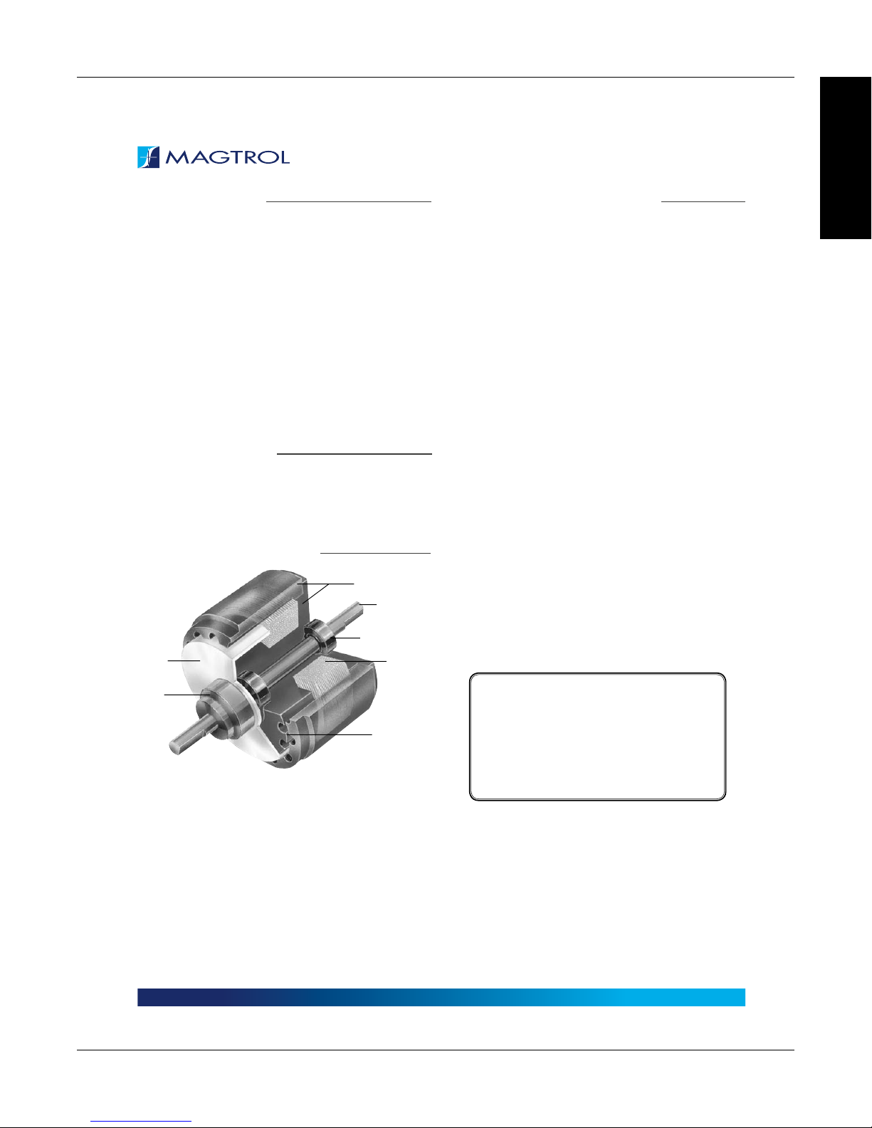
OPERATING PRINCIPLES
POLE STRUCTURE
SHAFT
BALL BEARINGS
OTOR
HUB
AIR GAP
Magtrol Hysteresis Dynamometers absorb power with a
unique Hysteresis Braking System which provides frictionless
torque loading independent of shaft speed. The Hysteresis
Brake provides torque by the use of two basic components—a
reticulated pole structure and a specialty steel rotor/shaft
assembly—fitted together but not in physical contact. Until the
pole structure is energized, the drag cup can spin freely on its
shaft bearings. When a magnetizing force from the field coil is
applied to the pole structure, the air gap becomes a flux field
and the rotor is magnetically restrained, providing a braking
action between the pole structure and rotor.
DYNAMOMETER SELECTION
Magtrol’s Hysteresis Dynamometers cover a wide range of
Torque, Speed and Mechanical Power ratings. To select the
appropriate size Dynamometer for your motor testing needs,
you will need to determine the Maximum Torque, Speed and
Power applied to the Dynamometer.
MAXIMUM TORQUE
The Magtrol Hysteresis Absorption Dynamometer will develop
braking torque at any speed point, including low speed and stall
conditions (“0” rpm). It is important to consider all torque points
that are to be tested, not only rated torque, but also locked
rotor and breakdown torque. Dynamometer selection should
initially be based on the maximum torque requirement, subject
to determining the maximum power requirements.
MAXIMUM SPEED
This rating is to be considered independent of torque and
power requirements, and is the maximum speed at which the
Dynamometer can be safely run under free-run or lightly loaded
conditions. It is not to be considered as the maximum speed at
which full braking torque can be applied.
MAXIMUM POWER RATINGS
These ratings represent the maximum capability of the
Dynamometer Braking System to absorb and dissipate heat
generated when applying a braking load to the motor under
test. The power absorbed and the heat generated by the
Dynamometer is a function of the Torque (T) applied to the motor
under test, and the resulting Speed (n) of the motor. This is
expressed in these power (P) formulas:
SI: P (watts) = T (N·m) × n (rpm) × (1.047 × 10
English: P (watts) = T (lb·in) × n (rpm) × (1.183 × 10
Metric: P (watts) = T (kg·cm) × n (rpm) × (1.027 × 10
All of Magtrol’s controllers, readouts and software
calculate horsepower as defined by 1 hp = 550 lb·ft / s.
Using this definition:
hp = P (watts) / 745.7
The Dynamometer’s ability to dissipate heat is a function of
how long a load will be applied. For this reason, the maximum
power ratings given are based on continuous operation under
load, as well as a maximum of 5 minutes under load.
To safely dissipate heat and avoid Dynamometer failure, the
maximum power rating is the most important consideration
in selecting a Dynamometer.
-1
)
-2
)
-2
)
|
Due to continual product development, Magtrol reserves the right to modify specifications without forewarning.
Page 2 / 16© 2016 MAGTROL
www.magtrol.comDATASHEET
11

Magtrol Hysteresis DynamometersChapter 1 – Introduction
HD SERIES
COMPLETE PC CONTROL
Magtrol’s M-TEST 7 Software is a state-of-the-art motor testing program for Windows®-based data acquisition. Used with a Magtrol
Programmable Dynamometer Controller, Magtrol M-TEST 7 Software provides the control of any Magtrol Dynamometer and runs test
sequences in a manner best suited to the overall accuracy and efficiency of the Magtrol Motor Test System. The data that is generated
by Magtrol’s Motor Testing Software can be stored, displayed and printed in tabular or graphic formats, and can be easily imported into
a spreadsheet.
Written in LabVIEW™, M-TEST 7 has the flexibility to test a majority of motor types in a variety of ways. Because of LabVIEW’s
versatility, obtaining data from other sources (e.g. thermocouples), controlling motor power and providing audio/visual indicators
is relatively easy.
Magtrol’s M-TEST 7 Software is ideal for simulating loads, cycling the unit under test and motor ramping. Because it is easy to gather
data and duplicate tests, the software is ideal for use in engineering labs. Tests can be programmed to run on their own and saved
for future use allowing for valuable time savings in production testing and incoming/outgoing inspection.
SPECIFICATIONS
HD HYSTERESIS DYNAMOMETER RATINGS
MODEL
TORQUE
MEASURE
UNIT CODE
HD-106 5N
HD-100
HD-400
HD-500
HD-510
HD-505
HD-515
HD-700
HD-710
HD-705
HD-715
a) All -5N(A) dynamometers are 5 Volt Output. Contact Magtrol for 6N (English), 7N (Metric) and 8N (SI) Specications.
b) Note: Operating at the continuous power rating for periods of up to 4 hours is acceptable. However, operating for extended periods at high temperatures will
result in premature component and bearing failure. Limiting the length of the cycle and the component temperatures will guard against premature failure. Where
continuous duty is desired for longer time intervals, component temperatures should be maintained less than 100°C; monitoring the outside brake surface
temperature is a sufcient reference.
c) Requires air cooling provided by user. Regulator and lter package is provided as standard equipment on these units.
5N
5N
5N
5N
5N
5N
5N
5N
5N
5N
MAXIMUM
TORQUE
RANGE
a)
N·m
0.018 0.056 mN·m 7.04 × 10-79.54 × 10
0.08 0.64 mN·m 3.40 × 10-64.61 × 10
0.28 2 mN·m 1.55 × 10-52.10 × 10
0.85 5 mN·m 8.05 × 10-51.09 × 10
0.85 5 mN·m 8.05 × 10-51.09 × 10
1.70 10 mN·m 1.61 × 10-42.18 × 10
1.70 10 mN·m 1.61 × 10-42.18 × 10
3.10 0.013 N·m 5.51 × 10-47.47 × 10
3.10 0.013 N·m 5.51 × 10-47.47 × 10
6.20 0.023 N·m 1.10 × 10-31.49 × 10
6.20 0.023 N·m 1.10 × 10-31.49 × 10
DRAG TORQUE
DE-ENERGIZED AT
1,000 RPM
NOMINAL INPUT INERTIA
2
lb·ft·s
kg·m
MAX. POWER RATINGS
5 MINUTE CONTINUOUS
2
W W
-7
35 7
-6
75 20 25,000
-5
200 55 25,000
-4
400 80 25,000
-4
750 375 25,000
-4
800 160 25,000
-4
1,500 900 25,000
-4
700 150 25,000
-4
1,500 935 25,000
-3
1,400 300 25,000
-3
3,400 3,000 25,000
MAXIMUM
b)
SPEED
30,000
RPM
BRAKE
COOLING
METHOD
Convection
Convection
Convection
Convection
Compressed
c)
Air
(7 CFM @
1.75 PSI)
Convection
Compressed
c)
Air
(10 CFM @
4 PSI)
Convection
Blower
(included)
Convection
Blower
(included)
INFORMATION
GENERAL
|
Due to continual product development, Magtrol reserves the right to modify specifications without forewarning.
Page 3 / 16© 2016 MAGTROL
www.magtrol.comDATASHEET
12

Magtrol Hysteresis Dynamometers
SPECIFICATIONS
HD-800
HD-810
HD-805
HD-815
HD-825
a) All -5N(A) dynamometers are 5 Volt Output. Contact Magtrol for 6N (English), 7N (Metric) and 8N (SI) Specications.
b) Note: Operating at the continuous power rating for periods of up to 4 hours is acceptable. However, operating for extended periods at high temperatures will
result in premature component and bearing failure. Limiting the length of the cycle and the component temperatures will guard against premature failure. Where
continuous duty is desired for longer time intervals, component temperatures should be maintained less than 100°C; monitoring the outside brake surface
temperature is a sufcient reference.
c) Requires air cooling provided by user. Regulator and lter package is provided as standard equipment on these units.
5N
5N
5N
5N
5N
14.00 0.10 N·m 4.43 × 10-36.01 × 10
14.00 0.10 N·m 4.43 × 10-36.01 × 10
28.00 0.14 N·m 8.81 × 10-31.19 × 10
28.00 0.14 N·m 8.81 × 10-31.19 × 10
56.50 0.22 N·m 1.85 × 10-22.51 × 10
-3
2,800 1,800 12,000
-3
3,500 3,000 12,000
-2
5,300 3,000 12,000
-2
7,000 6,000 12,000
-2
14,000 12,000 8,000
Chapter 1 – Introduction
HD SERIES
Compressed
c)
Air
(13 CFM @
10 PSI)
Blower
(included)
Compressed
c)
Air
(15 CFM @
14 PSI)
Blower
(included)
Blower
(included)
INFORMATION
GENERAL
ED ENGINE DYNAMOMETER RATINGS
MAXIMUM
TORQUE
a)
RANGE
N·m
MODEL
TORQUE
MEASURE
UNIT CODE
ED-715 5N
ED-815
a) All -5N(A) dynamometers are 5 Volt Output. Contact Magtrol for 6N (English), 7N (Metric) and 8N (SI) Specications.
b) Note: Operating at the continuous power rating for periods of up to 4 hours is acceptable. However, operating for extended periods at high temperatures will
result in premature component and bearing failure. Limiting the length of the cycle and the component temperatures will guard against premature failure. Where
continuous duty is desired for longer time intervals, component temperatures should be maintained less than 100°C; monitoring the outside brake surface
temperature is a sufcient reference.
c) The maximum speed will depend on what type of keyway (if any) is used on the shaft. Unless specied, the dynamometer shaft will be made without a keyway.
5N
28.0 0.14 N·m 9.61 × 10-31.30 × 10
DRAG TORQUE
DE-ENERGIZED AT
1,000 RPM
NOMINAL INPUT INERTIA
2
lb·ft·s
kg·m
6.20 0.035 N·m 1.27 × 10-31.72 × 10
MAX. POWER RATINGS
5 MINUTE CONTINUOUS
2
W W
-3
3,400 3,000
-2
7,000 6,000 12,000
MAXIMUM
b)
SPEED
25,000
RPM
c)
BRAKE
COOLING
METHOD
Blower
(included)
Blower
(included)
|
Due to continual product development, Magtrol reserves the right to modify specifications without forewarning.
Page 4 / 16© 2016 MAGTROL
www.magtrol.comDATASHEET
13

SPECIFICATIONS
Ø A
ELECTRICAL POWER AND FUSES
MODEL
HD-1XX-XN
HD-1XX-XNA
HD-4XX-XN
HD-4XX-XNA
HD-5XX-XN
HD-5XX-XNA
HD-800-XN
HD-800-XNA
HD-810-XN
HD-810-XNA
HD-805-XN
HD-805-XNA
HD/ED-815-XN
HD/ED-815-XNA
HD-825-XN
HD-825-XNA
VOLTAGE VA
120 V 30 UL/CSA 300 mA 250 V SB
240 V 30 IEC 125 mA 250 V T
120 V 30 UL/CSA 300 mA 250 V SB
240 V 30 IEC 125 mA 250 V T
120 V 30 UL/CSA 300 mA 250 V SB
240 V 30 IEC 125 mA 250 V T
120 V 65 UL/CSA 800 mA 250 V SB
240 V 65 IEC 315 mA 250 V T
120 V 65 UL/CSA 800 mA 250 V SB
240 V 65 IEC 315 mA 250 V T
120 V 130 UL/CSA 1.25 A 250 V SB
240 V 130 IEC 630 mA 250 V T
120 V 130 UL/CSA 1.25 A 250 V SB
240 V 130 IEC 630 mA 250 V T
120 V
240 V
Magtrol Hysteresis DynamometersChapter 1 – Introduction
INFORMATION
GENERAL
HD SERIES
STYLE RATING
N/A N/A N/A
N/A N/A N/A
BLOWER POWER AND FUSES
MODEL
BL-001
BL-001A
BL-002
BL-002A
VOLTAGE VA
120 V
240 V
120 V
240 V
1,000
1,000
600
500
BLOWER DIMENSIONS
MODEL
Ø A 6 152
A 11 279
B 6 152
C 8 203
D 4 102
E 8 203
F 1 25
Weight 8.5 lb 3.9 kg
BL-001
in mm in mm
11
15
12
18 lb
BL-002
6
6
4
1
STYLE RATING
6.3 A 250 V SB
3.15 A 250 V T
15 A 250 V SB
6.3A 250 V T
Air Filter
Dyno. Brake
Air Outlet
On/Off
Switch
D
152
279
152
381
102
302
25
8.1 kg
UL/CSA
IEC
UL/CSA
IEC
120 VAC 60 Hz
▪ Models HD-710, HD-715, HD-810 and
ED-715 include the BL-001 blower.
▪ Models HD-815 and ED-815 include the
BL-002 blower.
▪ Model HD-825 uses two BL-002 blowers
for cooling its two brake sets.
Allow approximately 6 in to 8 in
E
(152 mm to 203 mm) between rear
of dynamometer base plate and
B
C
blower for connection hardware.
Required hardware is supplied with
the dynamometer.
BL-002 Blower has two filter elements.
FG
|
Due to continual product development, Magtrol reserves the right to modify specifications without forewarning.
Page 5 / 16© 2016 MAGTROL
www.magtrol.comDATASHEET
14
Magtrol Hysteresis Dynamometers
F
D
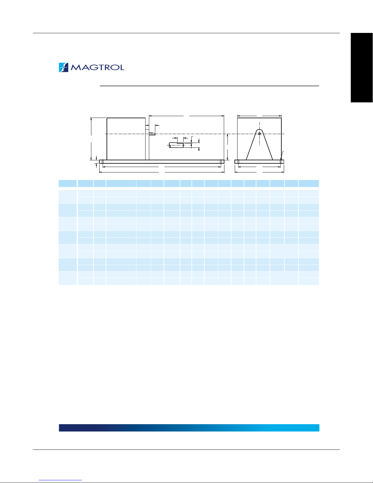
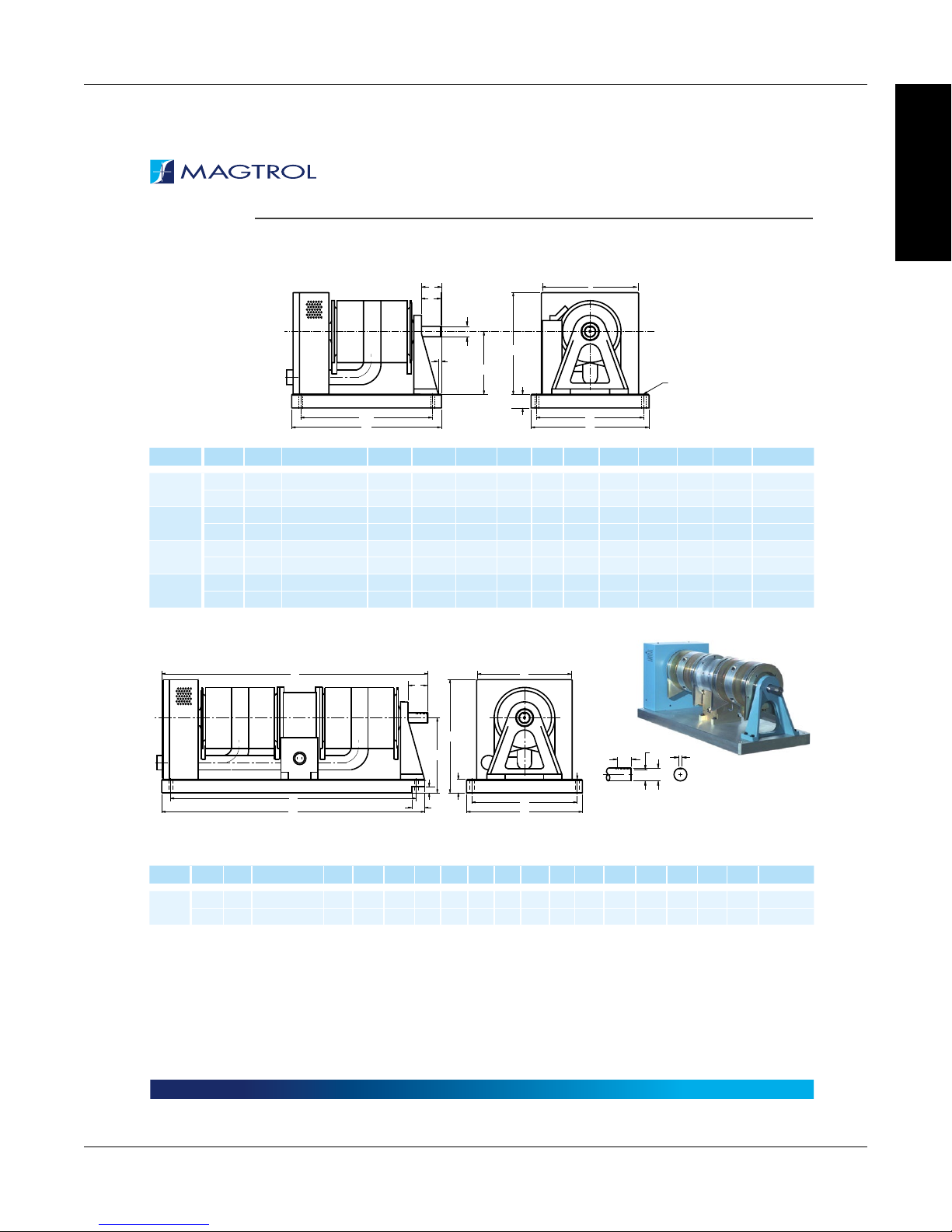
DIMENSIONS
NOTE: Original dimensions are in English units. Dimensions converted to Metric units have been rounded and are for reference only.
HD-100/400/500 SERIES WITH LONG BASE PLATE
Chapter 1 – Introduction
INFORMATION
GENERAL
HD SERIES
E
A
(FLAT)
P
ØB
C
a)Ma)
H
G
B
MODEL UNITS A
in
HD-106
HD-100
HD-400
HD-500
HD-510
HD-505
HD-515
a) These dimensions represent the distance between mounting holes. There are four (4) mounting holes on each base plate.
0.50 0.1245/0.1247 3.5 17 9.38 10 0.5 6.3 8.5 15.5 8.5 0.37 0.015 0.375
mm
12.7 3.162/3.167 88.9 432 238.3 254 12.7 159 216 394 216 9.4 0.38 9.53
in
0.75 0.1870/0.1875 3.5 17 9.13 10 0.5 6.3 8.5 15.5 8.5 0.37 0.025 0.375
mm
19.1 4.750/4.763 88.9 432 231.9 254 12.7 159 216 394 216 9.4 0.64 9.53
in
0.67 0.2495/0.2497 3.5 17 9.13 10 0.5 6.3 8.5 15.5 8.5 0.37 0.03 0.438
mm
17.0 6.337/6.342 88.9 432 231.9 254 12.7 159 216 394 216 9.4 0.76 11.13
in
0.88 0.3745/0.3750 4.0 17 9.13 10 0.5 6.3 8.5 15.5 8.5 0.37 0.047 0.375
mm
22.2 9.512/9.525 101.6 432 231.9 254 12.7 159 216 394 216 9.4 1.19 9.53
in
0.88 0.3745/0.3750 4.0 17 9.13 10 0.5 6.3 8.5 15.5 8.5 0.37
mm
22.2 9.512/9.525 101.6 432 231.9 254 12.7 159 216 394 216 9.4
in
0.88 0.3745/0.3750 4.0 20 9.64 10 0.5 6.3 8.5 18.5 8.5 0.37 0.05 0.375
mm
22.2 9.512/9.525 101.6 508 244.9 254 12.7 159 216 470 216 9.4 1.27 9.53
in
0.88 0.3745/0.3750 4.0 20 9.64 10 0.5 6.3 8.5 18.5 8.5 0.37
mm
22.2 9.512/9.525 101.6 508 244.9 254 12.7 159 216 470 216 9.4
Ø
C D E F G H J L
Q
SHAFT END DETAIL (2:1)
L
J
M
Ø N
ØN
P Q WEIGHT
12.0 lb
5.4 kg
12.5 lb
5.7 kg
15.0 lb
6.8 kg
16.0 lb
7.3 kg
N/A
N/A
16.0 lb
7.3 kg
18.0 lb
8.1 kg
18.0 lb
8.1 kg
|
Due to continual product development, Magtrol reserves the right to modify specifications without forewarning.
Page 6 / 16© 2016 MAGTROL
www.magtrol.comDATASHEET
15
Magtrol Hysteresis DynamometersChapter 1 – Introduction
HD SERIES
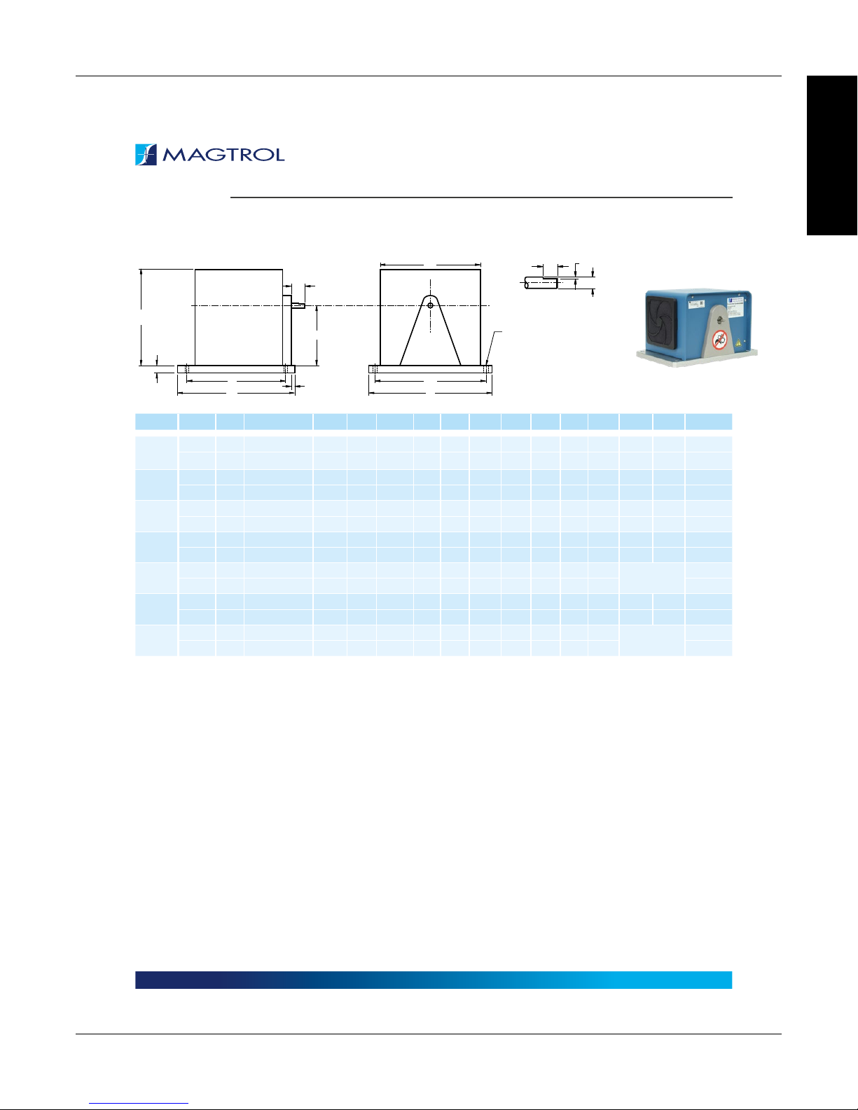
DIMENSIONS
NOTE: Original dimensions are in English units. Dimensions converted to Metric units have been rounded and are for reference only.
HD-100/400/500 SERIES WITH SHORT BASE PLATE
INFORMATION
GENERAL
J
A
H
C
G
L
D
MODEL UNITS A
in
HD-106
HD-100
HD-400
HD-500
HD-510
HD-505
HD-515
a) These dimensions represent the distance between mounting holes. There are four (4) mounting holes on each base plate.
0.50 0.1245/0.1247 3.5 7.0
mm
12.7 3.162/3.167 88.9 177.8
in
0.75 0.1870/0.1875 3.5 7.0
mm
19.1 4.750/4.763 88.9 177.8
in
0.67 0.2495/0.2497 3.5 7.0
mm
17.0 6.337/6.342 88.9 177.8
in
0.88 0.3745/0.3750 4.0 7.0
mm
22.2 9.512/9.525 101.6 177.8
in
0.88 0.3745/0.3750 4.0 8.0
mm
22.2 9.512/9.525 101.6 203.2
in
0.88 0.3745/0.3750 4.0 9.5
mm
22.2 9.512/9.525 101.6 241.3
in
0.88 0.3745/0.3750 4.0 10.25
mm
22.2 9.512/9.525 101.6 260.4
E
B
Ø
C D E F G H J L
0.33 11
8.4 279.4
0.08 11
2.1 279.4
0.08 11
2.1 279.4
0.08 11
2.1 279.4
0.13 11
3.2 279.4
0.10 11
2.6 279.4
0.10 11
2.6 279.4
M
F
0.5 6.3 8.5
12.7 159 216
0.5 6.3 8.5
12.7 159 216
0.5 6.3 8.5
12.7 159 216
0.5 6.3 8.5
12.7 159 216
0.5 6.3 8.5
12.7 159 216
0.5 6.3 8.5
12.7 159 216
0.5 6.3 8.5
12.7 159 216
Q
SHAFT END DETAIL (2:1)
ØN
152.4 250 9
152.4 250 9
152.4 250 9
152.4 250 9
177.8 250 9 5.7 kg
215.9 250 9
9.25 9.84 0.35
234.9 250 9 5.9 kg
P
(FLAT)
a)Ma)
6.0 9.84 0.35
6.0 9.84 0.35
6.0 9.84 0.35
6.0 9.84 0.35
7.0 9.84 0.35
8.5 9.84 0.35
ØB
Ø N
P Q WEIGHT
0.015 0.375
0.38 9.53
0.025 0.375
0.64 9.53
0.03 0.438
0.76 11.13
0.047 0.375
1.19 9.53
N/A
0.05 0.375
1.27 9.53
N/A
7.5 lb
3.4 kg
8.0 lb
3.6 kg
11.0 lb
5.0 kg
12.0 lb
5.4 kg
12.5 lb
13.0 lb
5.9 kg
13.0 lb
|
Due to continual product development, Magtrol reserves the right to modify specifications without forewarning.
Page 7 / 16© 2016 MAGTROL
www.magtrol.comDATASHEET
16
Magtrol Hysteresis Dynamometers
F
D
F
D
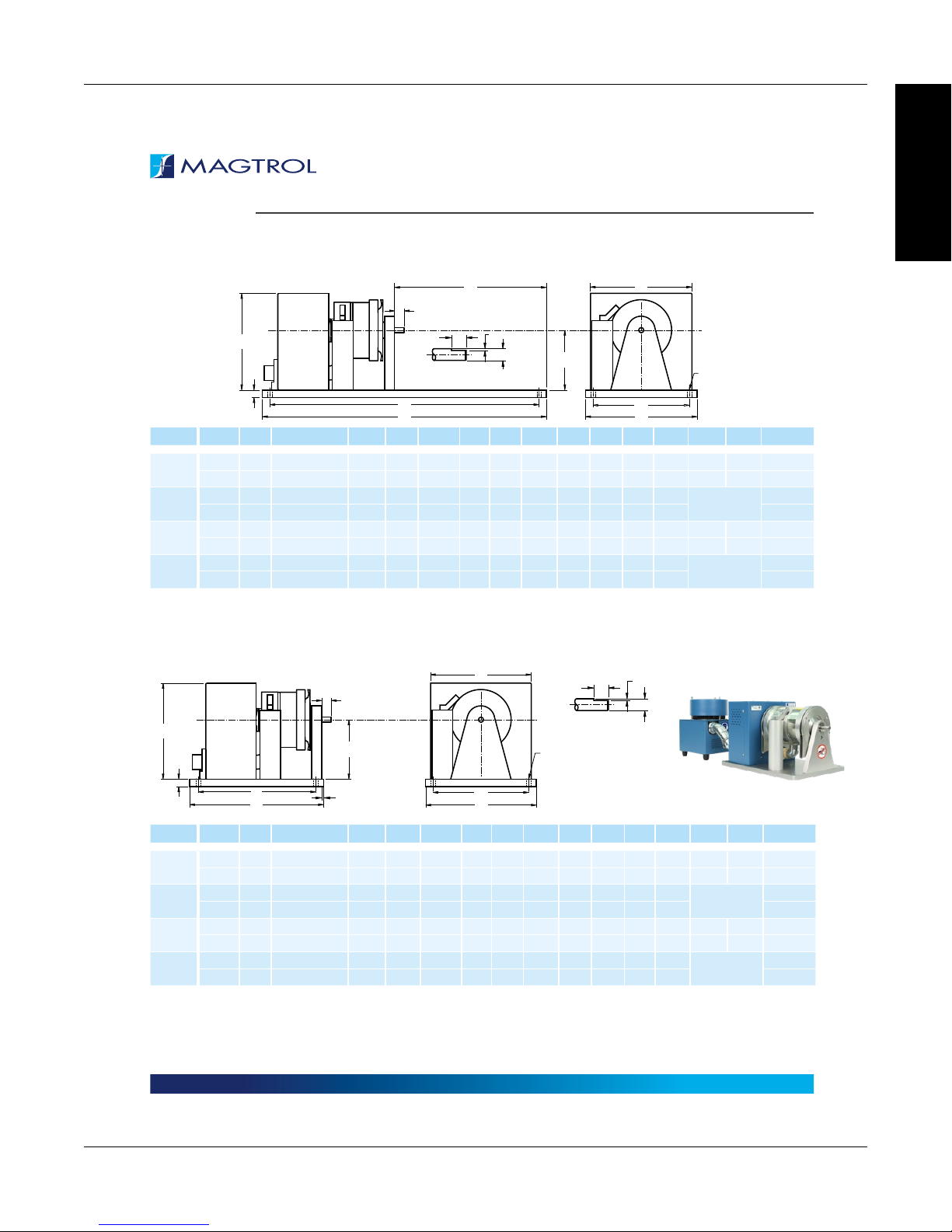
DIMENSIONS
NOTE: Original dimensions are in English units. Dimensions converted to Metric units have been rounded and are for reference only.
HD-700 SERIES WITH LONG BASE PLATE
H
G
E
A
Q
SHAFT END DETAIL (2:1)
(FLAT)
L
Chapter 1 – Introduction
INFORMATION
GENERAL
HD SERIES
J
P
ØB
C
ØN
M
B
MODEL UNITS A
HD-700
HD-710
HD-705
HD-715
a) These dimensions represent the distance between mounting holes. There are four (4) mounting holes on each base plate.
in 1.25 0.4995/0.4999 5.875 24 12.75 11 0.625 9.5 10 22.5 723.9 0.375 0.06 0.63 39 lb
mm 31.8 12.687/12.692 149.2 609.6 323.9 279.4 15.9 241.3 254 571.5 241.3 9.5 1.6 15.9 17.63 kg
in 1.25 0.4995/0.4999 5.875 26 13.59 11 0.625 9.5 10 24.5 9.5 0.375
mm 31.8 12.687/12.692 149.2 660.4 345.2 279.4 15.9 241.3 254 622.3 241.3 9.5 20.30 kg
in 1.25 0.4995/0.4999 5.875 28 13.62 11 0.625 9.5 10 26.5 9.5 0.375 0.06 0.63 52 lb
mm 31.8 12.687/12.692 149.2 711.2 346.0 279.4 15.9 241.3 254 673.1 241.3 9.5 1.6 15.9 23.50 kg
in 1.25 0.4995/0.4999 5.875 30 14.29 11 0.625 9.5 10 28.5 9.5 0.375
mm 31.8 12.687/12.692 149.2 762.0 363.0 279.4 15.9 241.3 254 723.9 241.3 9.5 26.60 kg
Ø
C D E F G H J L
a)Ma)
HD-700 SERIES WITH SHORT BASE PLATE
J
A
H
C
G
L
MODEL UNITS A
HD-700
HD-710
HD-705
HD-715
a) These dimensions represent the distance between mounting holes. There are four (4) mounting holes on each base plate.
in 1.25 0.4995/0.4999 5.875 11.34 0.09 11 0.625 9.5 10 9.84 9.84 0.375 0.06 0.63 30 lb
mm 31.8 12.687/12.692 149.2 288.0 2.2 279.4 15.9 241.3 254 250.0 250 9.5 1.6 15.9 13.6 kg
in 1.25 0.4995/0.4999 5.875 12.50 0.09 11 0.625 9.5 10 11.00 9.84 0.375
mm 31.8 12.687/12.692 149.2 317.5 2.2 279.4 15.9 241.3 254 279.5 250 9.5 16.3 kg
in 1.25 0.4995/0.4999 5.875 14.45 0.09 11 0.625 9.5 10 12.95 9.84 0.375 0.06 0.63 43 lb
mm 31.8 12.687/12.692 149.2 367.0 2.2 279.4 15.9 241.3 254 329.0 250 9.5 1.6 15.9 19.5 kg
in 1.25 0.4995/0.4999 5.875 15.75 0.09 11 0.625 9.5 10 14.25 9.84 0.375
mm 31.8 12.687/12.692 149.2 400.0 2.2 279.4 15.9 241.3 254 362.0 250 9.5 22.7 kg
E
B
Ø
C D E F G H J L
M
Q
SHAFT END DETAIL (2:1)
ØN
P
ØB
(FLAT)
a)Ma)
Ø N
P Q WEIGHT
Ø N
P Q WEIGHT
N/A
N/A
N/A
N/A
45 lb
59 lb
36 lb
50 lb
|
Due to continual product development, Magtrol reserves the right to modify specifications without forewarning.
Page 8 / 16© 2016 MAGTROL
www.magtrol.comDATASHEET
17
Magtrol Hysteresis DynamometersChapter 1 – Introduction
E
J
ØN
F
D
HD SERIES
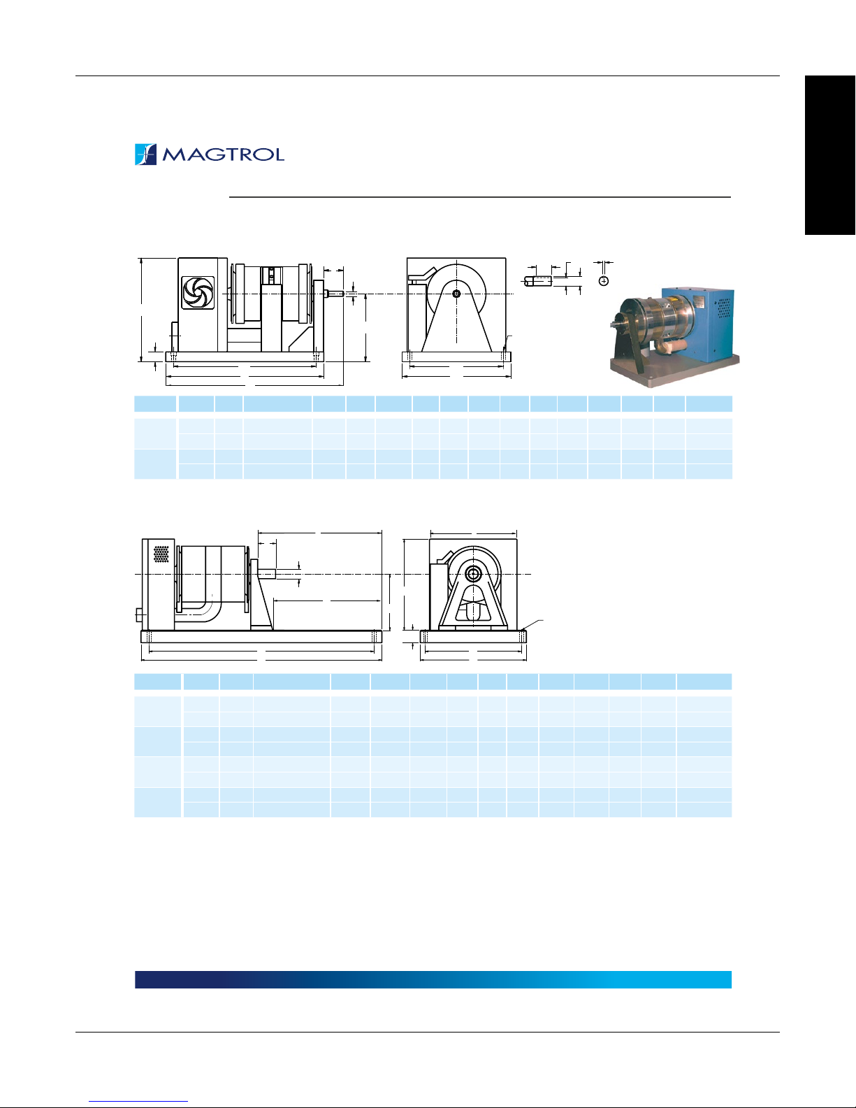
DIMENSIONS
NOTE: Original dimensions are in English units. Dimensions converted to Metric units have been rounded and are for reference only.
ED-SERIES ENGINE DYNAMOMETERS
A
H
G
B
C
Q
SHAFT END DETAIL (2:1)
ØN
P
(SQUARE KEY)
R
ØB
INFORMATION
GENERAL
L
D
B
MODEL UNITS A
ED-715
ED-815
a) These dimensions represent the distance between mounting holes. There are four (4) mounting holes on each base plate.
in 1.72 0.7490/0.7495 6.87 16.00 18.13 11.00 1.00 10.50 14.50 9.50 0.37 0.64 1.00 0.187 75 lb
mm 43.7 19.025/19.037 174.5 406.4 460.5 279.4 25.4 266.7 368.3 241.3 9.4 16.35 25.4 4.83 34 kg
in 3.02 1.4995/1.5000 11.00 23.00 23.27 17.00 2.00 16.63 20.80 15.00 5/8-11 1.287 2.00 0.375 285 lb
mm 76.7 38.087/38.100 279.4 584.2 591.1 431.8 50.8 422.4 528.3 381.0 THD 32.7 50.8 9.53 129.3 kg
Ø
C D E F G H L
M
F
a)Ma)
Ø N
HD-800 SERIES WITH LONG BASE PLATE
A
ØB
K
L
B
MODEL UNITS A
HD-800
HD-810
HD-805
HD-815
a) These dimensions represent the distance between mounting holes. There are four (4) mounting holes on each base plate.
in 2.13 0.9995/1.0000 9 38.5 23.81 17 2 14.6 14 36.5 15 0.53 237.0 lb
mm 54 25.387/25.400 228.6 978 605 432 50.8 371 356 927 381 13.5 107.2 kg
in 2.05 0.9995/1.0000 9 38.5 23.09 17 2 14.6 14 36.5 15 0.53 233.0 lb
mm 52 25.387/25.400 228.6 978 587 432 50.8 371 356 927 381 13.5 105.3 kg
in 2.13 0.9995/1.0000 9 38.5 20.57 17 2 14.6 14 36.5 15 0.54 287.0 lb
mm 54 25.387/25.400 228.6 978 522 432 50.8 371 356 927 381 13.7 129.7 kg
in 2.12 0.9995/1.0000 9 38.5 18.19 17 2 14.6 14 36.5 15 0.54 288.0 lb
mm 54 25.387/25.400 228.6 978 462 432 50.8 371 356 927 381 13.7 130.1 kg
Ø
C D E F G H J L
H
C
G
M
NOTE: For detailed dimension
drawings of dynamometers with
the T-slot base plate option, visit
Magtrol’s Web site.
P Q R WEIGHT
a)Ma)
Ø N
WEIGHT
|
Due to continual product development, Magtrol reserves the right to modify specifications without forewarning.
www.magtrol.comDATASHEET
Page 9 / 16© 2016 MAGTROL
18
Magtrol Hysteresis Dynamometers
ØN
F
D
F
D
DIMENSIONS
NOTE: Original dimensions are in English units. Dimensions converted to Metric units have been rounded and are for reference only.
HD-800 SERIES WITH SHORT BASE PLATES
Chapter 1 – Introduction
INFORMATION
GENERAL
HD SERIES
E
A
ØB
J
K
L
B
MODEL UNITS A
HD-800
HD-810
HD-805
HD-815
a) These dimensions represent the distance between mounting holes. There are four (4) mounting holes on each base plate.
in 2.13 0.9995/1.0000 9 17.25 2.56 17 2 14.6 14 13.78 15.75 0.35 168.0 lb
mm 54 25.387/25.400 228.6 438 65 432 50.8 371 356 350 400 9 76.2 kg
in 2.05 0.9995/1.0000 9 18.00 2.59 17 2 14.6 14 14.06 15.75 0.35 164.0 lb
mm 52 25.387/25.400 228.6 457 66 432 50.8 371 356 357 400 9 74.4 kg
in 2.13 0.9995/1.0000 9 20.50 2.57 17 2 14.6 14 15.75 15.75 0.35 228.0 lb
mm 54 25.387/25.400 228.6 520 65 432 50.8 371 356 400 400 9 103.4 kg
in 2.12 0.9995/1.0000 9 23.00 2.59 17 2 14.6 14 19.09 15.75 0.35 236.0 lb
mm 54 25.387/25.400 228.6 584 66 432 50.8 371 356 485 400 9 107.0 kg
Ø
E
L
C D E F G H J L
A
H
C
G
T
S
H
C
G
J
M
M
Q
ØN
SHAFT END DETAIL (2:1)
(SQUARE KEY)
a)Ma)
P
ØB
Ø N
WEIGHT
R
An HD-825 Dynamometer with long base plate is available if ordered with the accompanying dynamometer table (TAB 0825L).
Contact Magtrol for details.
MODEL UNITS A
B
Ø
C D E F G H J L
a)Ma)
Ø N
P Q R S T WEIGHT
HD-800
a) These dimensions represent the distance between mounting holes. There are four (4) mounting holes on each base plate.
in 2.83 1.4995/1.5000 11 38.5 38.93 17 2 16.6 14 36.5 15 0.54 1.287 2 0.376 2 1 400.0 lb
mm 72 38.087/38.100 279.4 978 989 432 50.8 422 356 927 381 13.7 32.69 50.8 9.53 50.8 25.4 181.4 kg
|
Due to continual product development, Magtrol reserves the right to modify specifications without forewarning.
Page 10 / 16© 2016 MAGTROL
www.magtrol.comDATASHEET
19
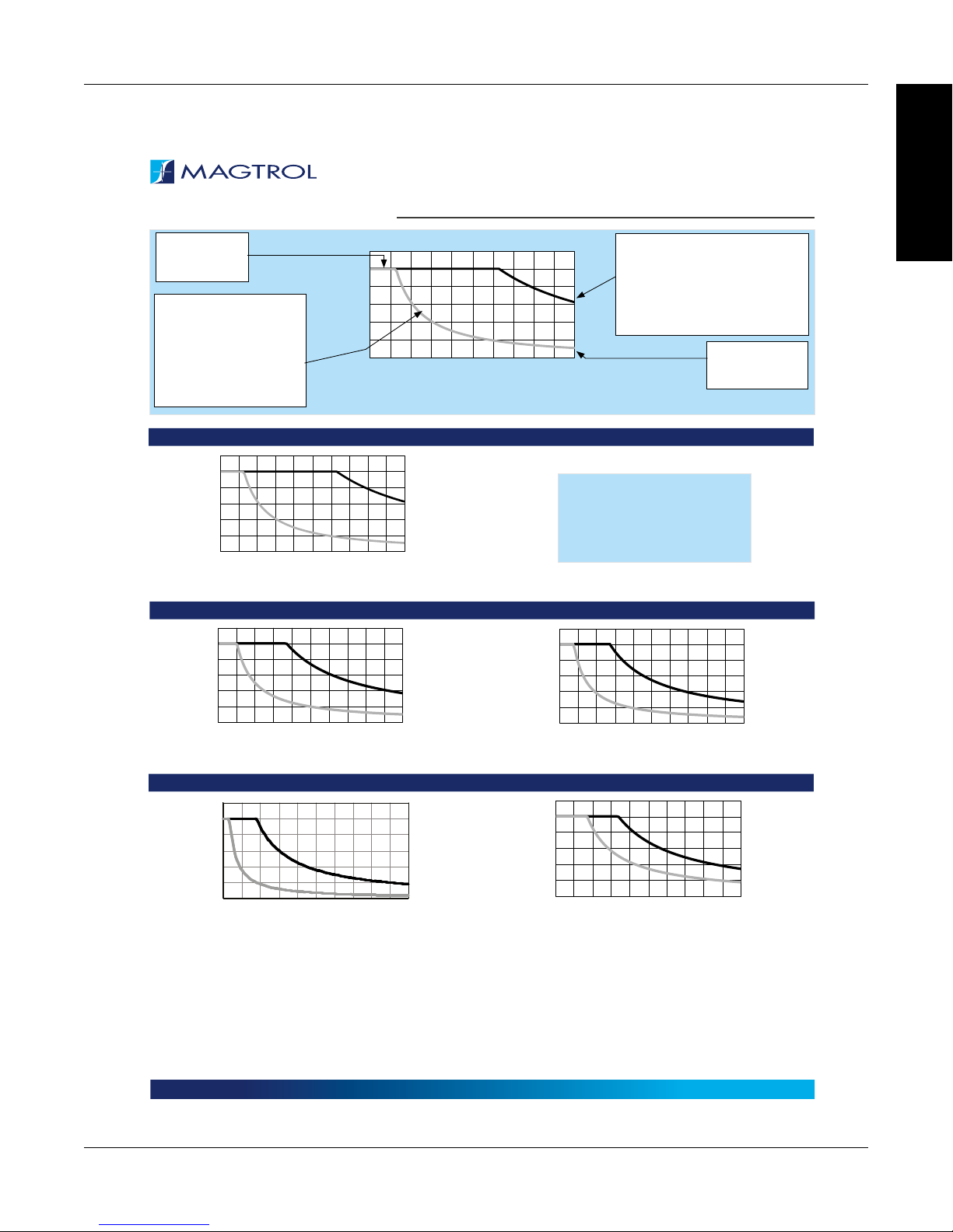
POWER ABSORPTION CURVES
Magtrol Hysteresis DynamometersChapter 1 – Introduction
INFORMATION
GENERAL
HD SERIES
Maximum Rated
Speed for
Dynamometer
Maximum Kinetic
Power Rating Curve for
Continuous Duty: Area
under curve equals the
maximum speed and
torque combinations for a
continuous duty motor test.
36000
30000
24000
18000
12000
SPEED (rpm)
6000
0
000.5
3.617.2
30000
25000
20000
15000
10000
SPEED (rpm)
5000
0
002.2164.4326.6488.86411
30000
25000
20000
15000
10000
SPEED (rpm)
5000
0
0024
170483407251096680
36000
30000
24000
18000
12000
SPEED (rpm)
6000
0
000.5
3.617.2
1.5
10.8214.4
2.5
18
Maximum Kinetic Power Rating
Curve for Less Than Five Minutes:
Area under curve equals the
maximum speed and torque
combinations for a motor test of
less than five minutes.
(oz·in)
(mN·m)
TORQUE
HD-106
The power absorption curves
represent the maximum power
(heat) that the dynamometer can
dissipate over time.
10.8214.4
TORQUE
1.5
2.5
18
(oz·in)
(mN·m)
HD-100 HD-400
30000
25000
20000
15000
10000
SPEED (rpm)
5000
0
0
085616112241683222440280
TORQUE
TORQUE
80
(oz·in)
(mN·m)
HD-500 HD-510
30000
25000
20000
15000
10000
SPEED (rpm)
5000
0
0024
170483407251096680
TORQUE
TORQUE
120
850
(oz·in)
(mN·m)
Maximum Torque
for Dynamometer
(oz·in)
(mN·m)
(oz·in)
120
(mN·m)
850
|
Due to continual product development, Magtrol reserves the right to modify specifications without forewarning.
Page 11 / 16© 2016 MAGTROL
www.magtrol.comDATASHEET
20
Magtrol Hysteresis Dynamometers
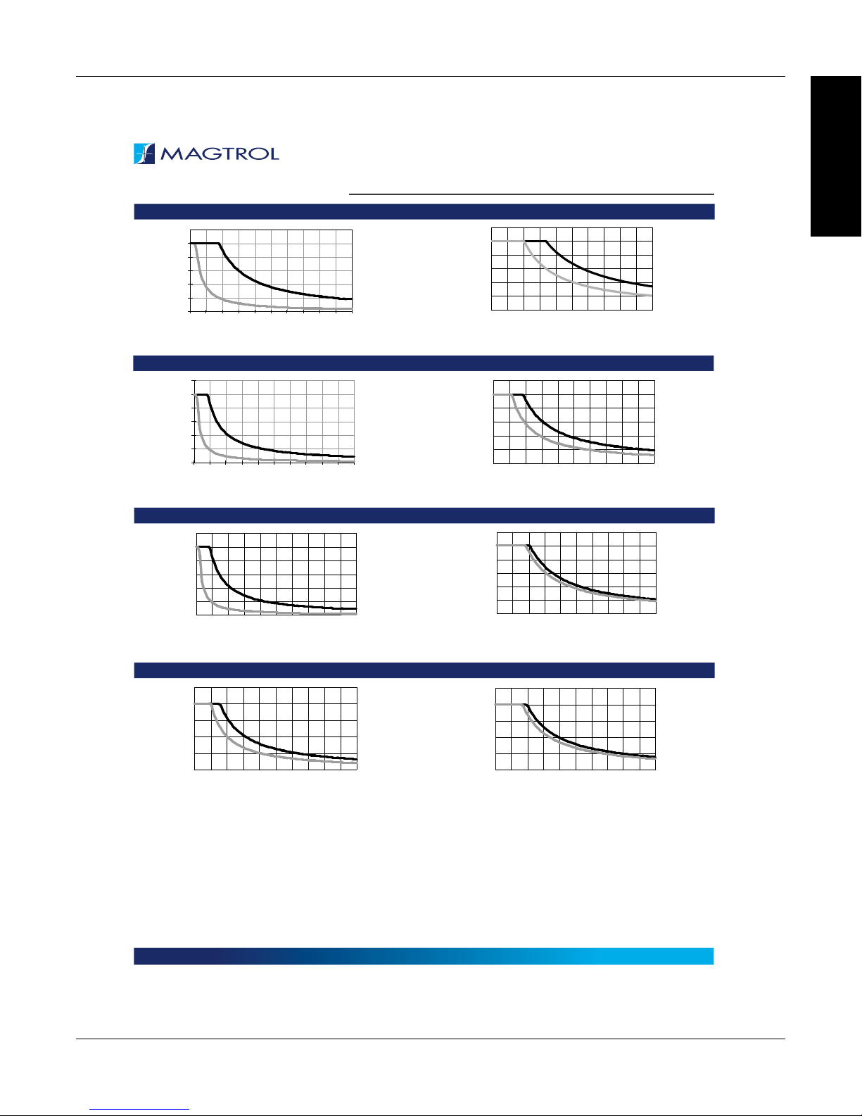
POWER ABSORPTION CURVES
HD-505 HD-515
30000
25000
20000
15000
10000
SPEED (rpm)
5000
0
0048
34096680
TORQUE
HD-700 HD-710
30000
25000
20000
15000
10000
SPEED (rpm)
5000
0
0088
30000
25000
20000
15000
10000
SPEED (rpm)
5000
0
0011
176
0.62
1.24
TORQUE
HD-705 HD-715 AND ED-715
1.24222.48333.72444.96556.20
TORQUE
144
1020
264
1.86
192
1360
352
2.48
240
1700
440
3.10
(oz·in)
(mN·m)
(oz·in)
(N·m)
(lb·in)
(N·m)
30000
30000
25000
25000
20000
20000
15000
15000
10000
10000
SPEED (rpm)
5000
5000
0
0
0048
30000
25000
20000
15000
10000
SPEED (rpm)
5000
0
0088
30000
25000
20000
15000
10000
SPEED (rpm)
5000
0
0011
Chapter 1 – Introduction
144
34096680
TORQUE
176
0.62
1.24
TORQUE
1.24222.48333.72444.96556.20
TORQUE
1020
264
1.86
192
1360
352
2.48
1700
HD SERIES
240
(oz·in)
(mN·m)
(oz·in)
440
(N·m)
3.10
(lb·in)
(N·m)
INFORMATION
GENERAL
15000
12000
9000
6000
SPEED (rpm)
3000
0
0025
|
Due to continual product development, Magtrol reserves the right to modify specifications without forewarning.
HD-800 HD-810
2.8505.6758.4
TORQUE
100
11.2
125
14.0
(lb·in)
(N·m)
21
15000
12000
9000
6000
SPEED (rpm)
3000
0
0025
2.8505.6758.4
TORQUE
100
11.2
www.magtrol.comDATASHEET
125
14.0
(lb·in)
(N·m)
Page 12 / 16© 2016 MAGTROL
 Loading...