

Model DSP7000
High Speed Programmable
Dynamometer Controller
User’s Manual

Purchase Record
Please record all model numbers and serial numbers of your
Magtrol equipment, along with the general purchase information.
The model number and serial number can be found on either
a silver identification plate or white label affixed to each unit.
Refer to these numbers whenever you communicate with a
Magtrol representative about this equipment.
Model Number: _____________________________
Serial Number: _____________________________
Purchase Date: _____________________________
Purchased From: _____________________________
While every precaution has been exercised in the compilation of this document to
ensure the accuracy of its contents, Magtrol, Inc. assumes no responsibility for errors or
omissions. Additionally, no liability is assumed for any damages that may result from the
use of the information contained within this publication.
COPYRIGHT
Copyright ©2011-2017 Magtrol, Inc. All rights reserved.
Copying or reproduction of all or any part of the contents of this manual without the
express permission of Magtrol is strictly prohibited.
TRADEMARKS
LabVIEW™ is a trademark of National Instruments Corporation.
Microsoft® is a registered trademark of Microsoft Corporation.
National Instruments™ is a trademark of National Instruments Corporation.
Windows® is a registered trademark of Microsoft Corporation.
2nd Edition rev. L – January 2017

Safety Precautions
1. Make sure that all Magtrol dynamometers and electronic products are earth-grounded, to ensure
personal safety and proper operation.
2. Check line voltage before operating the DSP7000.
3. Make sure that dynamometers and motors under test are equipped with appropriate safety
guards.
i

Revisions To This Manual
The contents of this manual are subject to change without prior notice. Should revisions be necessary, updates to all
Magtrol User’s Manuals can be found at Magtrol’s web site at www.magtrol.com/support/manuals.htm.
Please compare the date of this manual with the revision date on the web site, then refer to the manual’s Table of
Revisions for any changes/updates that have been made since this edition.
REVISION DATE
2nd Edition revision L– January 2017
TABLE OF REVISIONS
Date Edition Change Section(s)
01/05/17 2 nd Edition rev. L I/O Card specications updated. 8.1
04/05/16 2 nd Edition rev. K Torque Commands updated. 7.4.6
08/10/15 2 nd Edition rev. J USB driver setup for Windows operating system updated. 7.1.1
07/07/15 2 nd Edition rev. H Installation instructions and commands updated
throughout chapter.
07/07/15 2 nd Edition rev. H Setting tare function instructions updated. 6.7.1
07/07/15 2 nd Edition rev. H Alarm instuctions and commands updated throughout
chapter.
06-09-15 2 nd Edition rev. G Figure 2-12 RS-232 Interface drawing updated. 2.4.4
06/19/14 2 nd Edition rev. F A/D Sample Rate changed from 7812.5 KHz to 7812.5 Hz. 10.3
03/27/14 2 nd Edition rev. E Miscellaneous Commands updated. 7.4.7
10/28/13 2 nd Edition rev. D Speed commands table updated.
Chapter 7
Chapter 5
7.4.5
Figure 4-1 updated for new rmware.
Section updated for new rmware.
07/11/13 2 nd Edition rev. C Note added to Calibration Frequency procedure. 9.3.4
07/03/13 2 nd Edition rev. B Step number 5 updated in Calibration Procedure of Digital
to Analog Converters.
07/03/13 2 nd Edition rev. B Step number 4 updated in Calibration Prodedure of
Analog to Digital Converters.
05/23/13 2 nd Edition rev. A Calibration procedure of Analog to Digital Converters
updated.
05/23/13 2 nd Edition rev. A Digital input and output added to specications. 8.1
03/09/13 2 nd Edition Torque invert signal added. B.3.4
03/09/13 2 nd Edition Prcedure for setting the scale factor updated. 10.2.1.1, 10.2.1.2,
03/09/13 2 nd Edition Calibration Procedure updated. 9.3, 9.3.3
03/09/13 2 nd Edition New drawing added. 8.2.3, 8.2.4
03/09/13 2 nd Edition Pin 25 updated to Alarm Relay 2 Common. 8.1.2
03/09/13 2 nd Edition QDS1,xx.xx, QDS2,xx.xx; QIS1,xx.xx, QIS2,xx.xx;
QPS1,xx.xx, QPS2,xx.xx commands updated.
03/09/13 2 nd Edition NDSI1,#, NDSI2,#; NISI1,#, NISI2,#; NPSI1,#, NPSI2,#
commands updated.
4.3.1
6.6
9.3.3
9.3.2
9.3.2
10.2.1.3
7.4.6
7.4.5
ii

Date Edition Change Section(s)
03/09/13 2 nd Edition Din1,#, Din2,# command updated.
7.4.4
TAC1,#, TAC2,# command updated.
03/09/13 2 nd Edition Drawing updated 3.2.4.1, 3.2.5.1,
3.2.7.1, 3.2.8.1,
3.2.9.1, 3.2.10.1
03/09/13 2 nd Edition Note updated with correct section number for the Torque
3.2.1
Filter information.
03/09/13 2 nd Edition New features updated. 1.2
02/20/13 1st Edition - rev. Q One “x” added to the OD1, OD2 command to show a
7.4.2
return of 6 speed digits.
02/13/13 1st Edition - rev. P Section 6.8 How to Set the TM/TF Invert Flag added.
6.8
DINØ, DIN1 changed to DIRØ, DIR1 in the note section.
7.5
01/31/13 1st Edition - rev. O Step added to the setup instructions. 4.3.1
01/25/13 1st Edition - rev. N TMV1,# and TMV2,# command added.
A note was added to the DSP6001 Mode instructions.
01/04/13 1st Edition - rev. M F1,xx.xx and F2,xx.xx command function and denition
7.4.7
7.5
7.4.5
updated.
11/14/12 1st Edition - rev. L OS,# miscellaneous command added.
Calibration of Frequency added to the calibration
7.4.7
9.3.4
procedures.
10/26/12 1st Edition - rev. K The Supply 1/Supply 2 pin descriptions updated. 2.4.1
05/29/12 1st Edition - rev. J Power Supply connector description changed to include
1.3
HD 825 dynamometers.
04/25/12 1st Edition - rev. I Brake fuse changed to 1.25 Amps.
Congure Output Binary table descriptions updated.
1.3
7.2.2
03/14/12 1st Edition - rev. H OV,# command updated for both channels. 7.4.7
01/12/12 1st Edition - rev. G Section 6.6 How to Set Preload Control and section 6.7
6.6, 6.7
How to Set and Reset Tare Function was added.
The ALC,# Alarm Command was added to section 7.4.1.
7.4.1, 7.4.7
The TS1, TS2, TR1 and TR2 Commands were added to
section 7.4.7.
01/09/12 1st Edition - rev. F Driver and Tera Term location changed to Magtrol Manual CD7.1.1, 7.1.2, 8.4.2
12/27/11 1st Edition - rev. E USB Driver setup updated. 7.1.1, 7.1.2
12/13/11 1st Edition - rev D “Open or 8 Volts” was changed to “Open collector” for pin
9 in section 8.1.2. Function was changed for ALR1,# and
ALR2,# in section 7.4.1.
12/06/11 1st Edition - rev C RPM vs PPR Chart added 3.4
12/02/11/ 1st Edition - rev B STAT command was updated in section 7.4.7 to include
ramp down, ramp up, and mode input. The OP command
was added in section 7.4.8.
11/14/11 1st Edition - rev A Contact Rating changed from 1 amp, 24 VDC to 24 VDC,
1 amp max.
8.1.2, 7.4.1
7.4.7, 7.4.8
5.1.1, 8.1.2
iii

Table of Contents
SAFETY PRECAUTIONS ......................................................................................................................... I
REVISIONS TO THIS MANUAL ............................................................................................................... II
REVISION DATE ................................................................................................................................................................. II
TABLE OF REVISIONS ...................................................................................................................................................... II
TABLE OF CONTENTS .......................................................................................................................... IV
TABLE OF FIGURES .............................................................................................................................. IX
PREFACE ............................................................................................................................................... XII
PURPOSE OF THIS MANUAL ........................................................................................................................................XII
WHO SHOULD USE THIS MANUAL .............................................................................................................................XII
MANUAL ORGANIZATION ............................................................................................................................................XII
CONVENTIONS USED IN THIS MANUAL ................................................................................................................. XIII
1. INTRODUCTION ................................................................................................................................ 1
1.1 UNPACKING YOUR DSP7000 ..................................................................................................................................... 1
1.2 NEW FEATURES OF THE DSP7000 ........................................................................................................................... 1
1.3 DATA SHEET .................................................................................................................................................................2
2. CONTROLS ....................................................................................................................................... 10
2.1 FRONT PANEL ............................................................................................................................................................ 10
2.2 FRONT PANEL CONTROLS AND BUTTONS ......................................................................................................... 10
2.2.1 Enabling Secondary Functions ....................................................................................................................... 11
2.2.2 Enabling Saving Function .............................................................................................................................. 11
2.2.3 How to Use Front Panel Controls and Buttons .............................................................................................. 12
2.3 VACUUM FLUORESCENT DISPLAY (VFD) ........................................................................................................... 13
2.3.1 Contrast Settings ............................................................................................................................................ 14
2.3.2 Status Display Messages ................................................................................................................................ 14
2.4 REAR PANEL .............................................................................................................................................................. 15
2.4.1 Rear Panel Inputs and Outputs ....................................................................................................................... 15
2.4.2 Optional IO..................................................................................................................................................... 17
2.4.3 Optional GPIB ................................................................................................................................................ 18
2.4.4 Optional RS-232............................................................................................................................................. 18
3. INSTALLATION/CONFIGURATION .................................................................................................. 19
3.1 POWERING UP THE DSP7000 .................................................................................................................................. 19
3.1.1 Self-Test ......................................................................................................................................................... 19
3.1.2 Main Menu ..................................................................................................................................................... 20
3.2 INSTRUMENTATION SETUP (TORQUE) ................................................................................................................ 20
3.2.1 Dynamometer Configuration Menu ............................................................................................................... 21
3.2.2 Hysteresis Dynamometer Setup ..................................................................................................................... 22
3.2.3 Hysteresis Dynamometer with Transducer Setup .......................................................................................... 23
3.2.4 Hysteresis Dynamometer with Eddy-Current or Powder Brake Setup .......................................................... 24
3.2.5 Eddy-Current or Powder Brake Dynamometer Setup .................................................................................... 25
3.2.6 Eddy-Current or Powder Brake Dynamometer with Torque Transducer Setup ............................................. 27
3.2.7 Two Eddy-Current/Powder Brake Dynamometers (Independent Setup) ....................................................... 28
3.2.8 Two Eddy-Current/Powder Brake Dynamometers (Tandem Setup) .............................................................. 29
3.2.9 Eddy-Current Dynamometer with Powder Brake Dynamometer (Tandem Setup) ........................................ 31
3.2.10 In-Line Torque Transducer with Brake .......................................................................................................... 32
iv

3.3 TORQUE FILTER SETUP ........................................................................................................................................... 33
3.4 INSTRUMENTATION SETUP (SPEED) .................................................................................................................... 33
3.4.1 TACH A .......................................................................................................................................................... 35
3.4.2 QUAD DEG ................................................................................................................................................... 35
3.4.3 AI 1................................................................................................................................................................. 35
3.5 CONFIGURE COMMUNICATION ............................................................................................................................ 36
3.5.1 GPIB Address ................................................................................................................................................. 36
3.5.2 RS-232 Interface ............................................................................................................................................ 36
4. PID SETTINGS .................................................................................................................................. 37
4.1 ABOUT THE PID LOOP ............................................................................................................................................. 37
4.1.1 P (Proportional Gain) ..................................................................................................................................... 37
4.1.2 I (Integral) ...................................................................................................................................................... 37
4.1.3 D (Derivative) ................................................................................................................................................. 37
4.2 SETTING PID VALUES .............................................................................................................................................. 37
4.2.1 How To Set P (Proportional Gain) Value ....................................................................................................... 37
4.2.2 How to Set I (Integral) Value .......................................................................................................................... 37
4.2.3 How to Set D (Derivative) Value .................................................................................................................... 37
4.3 SETTING THE CORRECT PID’S FOR YOUR MOTOR .......................................................................................... 38
4.3.1 Setting the PID with an Unknown Motor or System ..................................................................................... 38
4.3.2 Setting the PID for Torque Control ................................................................................................................ 38
4.3.3 Setting the PID for Speed Control ................................................................................................................. 41
4.3.4 Setting the PID for Ramp Down .................................................................................................................... 43
5. ALARM SYSTEM .............................................................................................................................. 45
5.1 GENERAL INFORMATION ....................................................................................................................................... 45
5.1.1 Alarm Relay (IO Card Option) ...................................................................................................................... 45
5.1.2 Alarm Operation............................................................................................................................................. 46
5.1.3 Alarm Priority ................................................................................................................................................ 47
5.2 POWER ALARM ......................................................................................................................................................... 47
5.2.1 Instructions for Power Alarm Setup ............................................................................................................... 47
5.2.2 Power Alarm Action ....................................................................................................................................... 47
5.2.3 To Reset Power Alarm .................................................................................................................................... 48
5.3 GLOBAL POWER ALARM ........................................................................................................................................ 48
5.3.1 Instructions for Global Power Alarm Setup ................................................................................................... 48
5.3.2 Global Power Action ...................................................................................................................................... 49
5.3.3 to reset global power alarm ............................................................................................................................ 49
5.4 MAXIMUM SPEED ALARM .................................................................................................................................... 49
5.4.1 Instructions for Maximum Speed Alarm Setup .............................................................................................. 49
5.4.2 Maximum Speed Alarm Action ...................................................................................................................... 50
5.4.3 To Reset Maximum Speed Alarm .................................................................................................................. 50
5.5 MAXIMUM TORQUE ALARM ................................................................................................................................ 50
5.5.1 Instructions for Maximum Torque Alarm Setup ............................................................................................50
5.5.2 Maximum Torque Alarm Action .................................................................................................................... 51
5.5.3 To Reset Maximum Torque Alarm ................................................................................................................. 51
5.6 GLOBAL TORQUE ALARM ...................................................................................................................................... 52
5.6.1 Instructions for Global Torque Alarm Setup .................................................................................................. 52
5.6.2 Global Torque Action ..................................................................................................................................... 52
5.6.3 To Reset Global Torque Alarm ....................................................................................................................... 52
v

5.7 AIR FLOW ALARM .................................................................................................................................................... 52
5.7.1 Instructions for Air Flow Alarm Setup ........................................................................................................... 52
5.7.2 Air Flow Alarm Action ................................................................................................................................... 53
5.7.3 To Reset Air Flow Alarm ............................................................................................................................... 53
5.8 WATER FLOW ALARM ............................................................................................................................................. 54
5.8.1 Instructions for Water Flow Alarm Setup ....................................................................................................... 54
5.8.2 Water Flow Alarm Action .............................................................................................................................. 54
5.8.3 To Reset Water Flow Alarm ........................................................................................................................... 54
5.9 EXTERNAL ALARM (I/O CARD OPTION) ............................................................................................................. 55
5.9.1 Instructions for External Alarm Setup............................................................................................................55
5.9.2 External Alarm Action....................................................................................................................................55
5.9.3 To Reset External Alarm ................................................................................................................................ 55
5.10 TEMPERATURE ALARM (WB/PB ONLY) .............................................................................................................. 56
5.10.1 Instructions for Temperature Alarm Setup ..................................................................................................... 56
5.10.2 Temperature Alarm Action ............................................................................................................................. 56
5.10.3 To Reset Temperature Alarm .......................................................................................................................... 56
5.11 ELECTRICAL ALARM .............................................................................................................................................. 56
5.11.1 Instructions for Electrical Alarm Setup .......................................................................................................... 56
5.11.2 Electrical Alarm Action .................................................................................................................................. 56
5.11.3 To Reset Electrical Alarm .............................................................................................................................. 57
5.12 CLUTCH ALARM (WB/PB ONLY) ........................................................................................................................... 57
5.12.1 Clutch Alarm Action ...................................................................................................................................... 57
5.12.2 To Reset Clutch alarm .................................................................................................................................... 57
6. MANUALLY CONTROLLED OPERATION ....................................................................................... 58
6.1 HOW TO SET DESIRED POWER UNITS ................................................................................................................ 58
6.2 HOW TO SET DESIRED TORQUE UNITS .............................................................................................................. 58
6.3 HOW TO SET TORQUE CONTROL .......................................................................................................................... 59
6.4 HOW TO SET SPEED CONTROL .............................................................................................................................60
6.5 HOW TO SET OPEN LOOP CONTROL .................................................................................................................... 61
6.6 HOW TO SET PRELOAD CONTROL ....................................................................................................................... 61
6.7 HOW TO SET AND RESET TARE FUNCTION ........................................................................................................ 62
6.7.1 Setting the Tare Function ............................................................................................................................... 62
6.7.2 Resetting the Tare Function ............................................................................................................................ 62
6.8 HOW TO SET THE TM/TF INVERT FLAG .............................................................................................................. 63
7. COMPUTER CONTROLLED OPERATION ...................................................................................... 64
7.1 ABOUT THE USB INTERFACE ................................................................................................................................ 64
7.1.1 USB Driver Setup for Windows Operation System ....................................................................................... 64
7.1.2 Checking the DSP7000-To-PC Connection for GPIB Setup .........................................................................70
7.2 DATA FORMAT ........................................................................................................................................................... 71
7.2.1 Output Data (OD) ........................................................................................................................................... 71
7.2.2 Output Binary Command (OB) ...................................................................................................................... 72
7.3 PROGRAMMING ....................................................................................................................................................... 73
7.3.1 Data Termination Characters .......................................................................................................................... 73
7.3.2 Timeout .......................................................................................................................................................... 74
7.4 DSP7000 COMMAND SET ........................................................................................................................................ 74
7.4.1 Alarm Commands .......................................................................................................................................... 75
7.4.2 Communication Commands ........................................................................................................................... 76
7.4.3 Ramp Commands ........................................................................................................................................... 77
vi

7.4.4 Setup Commands ........................................................................................................................................... 78
7.4.5 Speed Commands ........................................................................................................................................... 79
7.4.6 Torque Commands .........................................................................................................................................81
7.4.7 Miscellaneous Commands ............................................................................................................................. 82
7.4.8 Quadrature Commands................................................................................................................................... 83
7.5 6001 MODE ................................................................................................................................................................. 84
8. OPTIONAL EQUIPMENT .................................................................................................................. 85
8.1 I/O CARD 1 AND I/O CARD 2 ................................................................................................................................... 85
8.1.1 I/O Card Installation ....................................................................................................................................... 85
8.1.2 I/O Card Interface .......................................................................................................................................... 87
8.1.3 I/O Card Configuration .................................................................................................................................. 89
8.1.4 I/O Card 1/Card 2 Command Set ................................................................................................................... 92
8.2 GPIB INTERFACE ......................................................................................................................................................93
8.2.1 GPIB Card Installation ................................................................................................................................... 93
8.2.2 About the GPIB Interface ............................................................................................................................... 94
8.2.3 Installing the GPIB (IEEE-488) Connector Cable ......................................................................................... 95
8.2.4 Changing the GPIB Primary Address ............................................................................................................ 95
8.3 RS232 INTERFACE ..................................................................................................................................................... 96
8.3.1 RS-232 Installation......................................................................................................................................... 96
8.3.2 Connection ..................................................................................................................................................... 97
8.3.3 Communication Parameters ........................................................................................................................... 98
8.3.4 Baud Rate ....................................................................................................................................................... 98
8.4 CHECKING THE DSP7000-TO-PC CONNECTION ................................................................................................. 98
8.4.1 GPIB Communication check.......................................................................................................................... 98
8.4.2 RS232 Communication Check ..................................................................................................................... 101
9. CALIBRATION ................................................................................................................................ 107
9.1 CLOSED-BOX CALIBRATION ............................................................................................................................... 107
9.2 CALIBRATION SCHEDULE ....................................................................................................................................107
9.3 BASIC CALIBRATION PROCESS ........................................................................................................................... 107
9.3.1 Initial Calibration Procedure ........................................................................................................................ 107
9.3.2 Calibration of Analog to Digital Converters ................................................................................................ 108
9.3.3 Calibration of Digital to Analog Converters ................................................................................................ 109
9.3.4 Calibration Frequency .................................................................................................................................. 111
10. THEORY ........................................................................................................................................ 112
10.1 HOW THE PID LOOP WORKS ................................................................................................................................ 112
10.1.1 Scale Factors for Hysteresis, Eddy-Current and Powder Brake Dynamometers ......................................... 112
10.1.2 Speed Correction for WB (Eddy-Current Brake) Dynamometer ................................................................. 112
10.1.3 Equations ...................................................................................................................................................... 113
10.2 ADDITIONAL SCALE FACTOR ............................................................................................................................. 113
10.2.1 How To Set Additional Scale Factor ............................................................................................................113
10.3 FILTER PARAMETERS ........................................................................................................................................... 114
11. TROUBLESHOOTING ................................................................................................................... 115
APPENDIX A: INERTIA CORRECTION ............................................................................................. 116
A.1 INERTIAL EFFECT ON MOTOR TEST DATA ....................................................................................................... 116
A.2 PROCEDURE FOR INERTIA CORRECTION ........................................................................................................ 116
A.2.1 Key Conditions ............................................................................................................................................. 117
vii

APPENDIX B: FRONT PANEL/DISPLAY MENU FLOW CHARTS ..................................................... 118
B.1 PRIMARY KEY FUNCTIONS.................................................................................................................................. 118
B.2 SECONDARY KEY FUNCTIONS ...........................................................................................................................119
B.2.1 Display Both................................................................................................................................................. 119
B.2.2 Setup ............................................................................................................................................................. 119
B.2.3 Power Units .................................................................................................................................................. 124
B.2.4 Torque Units ................................................................................................................................................. 125
B.2.5 Max Speed .................................................................................................................................................... 125
B.2.6 Scale P .......................................................................................................................................................... 126
B.2.7 Scale I ........................................................................................................................................................... 127
B.2.8 Scale D ......................................................................................................................................................... 128
B.3 TEST INSTRUMENT SETUP ................................................................................................................................... 129
B.3.1 Hysteresis Dynamometer Setup Menu ......................................................................................................... 129
B.3.2 Eddy-Curennt Dynamometer Setup Menu ................................................................................................... 130
B.3.3 Powder Brake Dynamometer Setup Menu ................................................................................................... 131
B.3.4 Torque Transducer/Torque Flange Sensor Setup Menu ............................................................................... 132
B.3.5 HD5 Setup Menu.......................................................................................................................................... 133
B.3.6 Eddy-Current Dynamometer with Eddy-Current Dynamometer (Tandem Setup) ...................................... 134
B.3.6 Powder Brake Dynamometer with Powder Brake Dynamometer (Tandem Setup) ..................................... 135
B.3.7 Eddy-Current Dynamometer with Powder Brake Dynamometer (Tandem Setup) ......................................136
APPENDIX C: SCHEMATICS .............................................................................................................. 137
C.1 DSP7000 CORE BLOCK ........................................................................................................................................... 137
C.2 DSP7000 ANALOG INPUTS .................................................................................................................................... 138
C.3 DSP7000 DIGITAL INPUTS ..................................................................................................................................... 139
C.4 DSP7000 ENCODER IN ............................................................................................................................................ 140
C.5 DSP7000 ANALOG OUTPUT................................................................................................................................... 141
C.6 DSP7000 DIGITAL OUTPUT ................................................................................................................................... 142
APPENDIX D: ADDITIONAL SCALE FACTOR TABLE ...................................................................... 143
SERVICE INFORMATION .................................................................................................................... 144
RETURNING MAGTROL EQUIPMENT FOR REPAIR AND/OR CALIBRATION .................................................... 144
Returning Equipment to Magtrol, Inc. (United States) .............................................................................................. 144
Returning Equipment to Magtrol SA (Switzerland) ................................................................................................... 144
viii

Table of Figures
2. CONTROLS
Figure 2–1 Front Panel ............................................................................................................................................10
Figure 2–2 Secondary Function Menu ......................................................................................................................11
Figure 2–3 Saving Function Menu ............................................................................................................................11
Figure 2–4 DSP7001 Rear Panel ..............................................................................................................................15
Figure 2–5 DSP7002 Rear Panel ..............................................................................................................................15
Figure 2–6 Dynamometer Brake Output ...................................................................................................................15
Figure 2–7 TSC1/TSC2 Connector ...........................................................................................................................16
Figure 2–8 Supply 1/Supply 2 Connector .................................................................................................................16
Figure 2–9 USB Connector .......................................................................................................................................16
Figure 2–10 I/O Interface Card 1 and Card 2 ..........................................................................................................17
Figure 2–11 GPIB Interface .....................................................................................................................................18
Figure 2–12 RS-232 Interface ...................................................................................................................................18
3. INSTALLATION/CONFIGURATION
Figure 3–1 Program Download Display ...................................................................................................................19
Figure 3–2 Revision Display .....................................................................................................................................19
Figure 3-3 Alarm Warning Display ...........................................................................................................................19
Figure 3–4 Main Menu .............................................................................................................................................20
Figure 3–5 Setup Menu ............................................................................................................................................21
Figure 3-6 Dyno Setup Menu ....................................................................................................................................21
Figure 3–7 Dynamometer Configuration Menu .........................................................................................................21
Figure 3–8 Hysteresis Dynamometer Setup ..............................................................................................................22
Figure 3–9 Hysteresis Setup Menu ...........................................................................................................................22
Figure 3–10 Hysteresis Dynamometer with Torque Transducer Setup .....................................................................23
Figure 3–11 Torque Transducer Setup Menu ............................................................................................................23
Figure 3–12 Hysteresis Dynamometer with Eddy-Current or Powder Brake Setup .................................................24
Figure 3–13 TSC2 Eddy-Current Setup Menu ..........................................................................................................24
Figure 3–14 TSC2 Powder Brake Setup Menu ..........................................................................................................25
Figure 3–15 Eddy-Current or Powder Brake Dynamometer Setup ..........................................................................25
Figure 3–16 TSC1 Eddy-Current Setup Menu ..........................................................................................................26
Figure 3-17 TSC1 Powder Brake Setup Menu ..........................................................................................................26
Figure 3–18 Eddy-Current or Powder Brake Dynamometer with Torque Transducer Setup ...................................27
Figure 3-19 TSC2 torque transducer setup menu .....................................................................................................27
Figure 3–20 Two Eddy-Current/Powder Brake Dynamometers (Independent Setup) ..............................................28
Figure 3-21 Tandem Setup Menu ..............................................................................................................................28
Figure 3–22 Tandem Configuration Menu ................................................................................................................29
Figure 3–22 Two Eddy-Current/Powder Brake Dynamometers (Tandem Setup) .....................................................29
Figure 3–23 Eddy-Current Dynamometer with Powder Brake Dynamometer (Tandem Setup) ...............................31
Figure 3–24 Maximum Speed Excited Menu ............................................................................................................32
Figure 3-25 In-Line Torque Transducer with Brake .................................................................................................32
Figure 3–26 TSC1 Setup Menu .................................................................................................................................33
Figure 3–27 RPM vs PPR Chart ...............................................................................................................................34
Figure 3–28 Encoder Menu ......................................................................................................................................35
Figure 3–29 QUAD DEG Menu ................................................................................................................................35
Figure 3–30 AI 1 Menu .............................................................................................................................................36
Figure 3–31 System Setup Menu ................................................................................................................................36
ix

4. PID SETTINGS
Figure 4–1 Open Loop Control Menu .......................................................................................................................38
Figure 4–2 Initial P Setting for Torque Control at 25% ...........................................................................................39
Figure 4–3 High Initial P Setting for Torque Control .............................................................................................39
Figure 4–4 Initial I Setting for Torque Control .........................................................................................................40
Figure 4–5 Initial D Setting for Torque Control .......................................................................................................40
Figure 4–6 Initial P Setting for Speed Control at 25% ..............................................................................................41
Figure 4–7 Initial I Setting for Speed Control ..........................................................................................................42
Figure 4–8 Initial D Setting for Speed Control .........................................................................................................42
Figure 4–9 Ramp Down Low I ..................................................................................................................................43
Figure 4–10 Ramp Down High I ...............................................................................................................................44
Figure 4–11 Ramp Down Dynamic I ........................................................................................................................44
5. ALARM SYSTEM
Figure 5–1 Normal Condition “Energized Relay” ...................................................................................................45
Figure 5–2 Alarm Condition “De-Energized Relay” ...............................................................................................45
Figure 5–3 Typical Application .................................................................................................................................46
Figure 5–4 Alarm Enable/Disable Menu ..................................................................................................................46
Figure 5–5 Max Power Menu ....................................................................................................................................47
Figure 5–6 Power -OL- Display ................................................................................................................................48
Figure 5–7 Power Alarm Display .............................................................................................................................48
Figure 5–8 Global Power Alarm Setup .....................................................................................................................48
Figure 5–9 Global Power Alarm Disply ...................................................................................................................49
Figure 5–10 Speed Alarm Setup Menu......................................................................................................................49
Figure 5–11 -OL- Speed Alarm Display ...................................................................................................................50
Figure 5–12 Over Speed Alarm Message Display ....................................................................................................50
Figure 5–13 Torque Alarm Setup Menu ....................................................................................................................51
Figure 5–14 -OL- Torque Alarm Display ..................................................................................................................51
Figure 5–15 Over Torque Alarm Message Display ...................................................................................................51
Figure 5 –16 Global Torque Alarm Setup .................................................................................................................52
Figure 5–17 Air Flow Alarm Setup Display .............................................................................................................53
Figure 5–18 Air Flow Alarm Message Display ........................................................................................................53
Figure 5–19 Water Flow Alarm Setup Display .........................................................................................................54
Figure 5–20 Water Flow Alarm Message Display ....................................................................................................54
Figure 5–21 External Alarm Setup Display ..............................................................................................................55
Figure 5–22 External Alarm Message Display .........................................................................................................55
Figure 5–23 Temperature Alarm Message Display ...................................................................................................56
Figure 5–24 Electrical Alarm Message Display .......................................................................................................57
Figure 5–25 Clutch Alarm Message Display ............................................................................................................57
6. MANUALLY CONTROLLED OPERATION
Figure 6–1 Power Units Menu ..................................................................................................................................58
Figure 6–2 Torque Units Menu .................................................................................................................................58
Figure 6–3 Torque Control Menu ..............................................................................................................................59
Figure 6–4 Max Speed Menu ....................................................................................................................................60
Figure 6–5 Preload Function enabled ......................................................................................................................61
Figure 6–6 Tare function enabled ............................................................................................................................62
Figure 6–7 Torque Invert Flag Screen ......................................................................................................................63
7. COMPUTER CONTROLLED OPERATION
Figure 7–1 Setup Menu .............................................................................................................................................84
Figure 7–2 System Setup Menu .................................................................................................................................84
x

8. OPTIONAL EQUIPMENT
Figure 8–1 DSP7000 Top Cover ...............................................................................................................................86
Figure 8–2 IO Card Installation ...............................................................................................................................86
Figure 8–3 I/O Card Interface ..................................................................................................................................87
Figure 8–4 Filter Channel Setup Menu.....................................................................................................................90
Figure 8-5 Offset and Gain Setup Menu ...................................................................................................................90
Figure 8–6 External Alarm Setup .............................................................................................................................90
Figure 8–7 Alarm Contact Setup...............................................................................................................................90
Figure 8–8 Torque/Speed Setup ................................................................................................................................91
Figure 8–9 Torque/Speed DAC Setup Menu ..............................................................................................................91
Figure 8–10 GPIB Card Installation ........................................................................................................................94
Figure 8–11 GPIB Installation ................................................................................................................................95
Figure 8–12 Setup Menu Display ...............................................................................................................................95
Figure 8–13 RS-232 Interface ...................................................................................................................................96
Figure 8–15 Straight Through Pin-to-Pin Cable Connection ...................................................................................97
Figure 8–18 Connected Instruments Window .........................................................................................................100
Figure 8–19 Communication with Instrument Window ..........................................................................................100
Figure 8–20 Query Window ....................................................................................................................................101
Figrue 8–21 Tera Term Setup Window ....................................................................................................................101
Figure 8–22 Tera Term Licence Agreement Window ...............................................................................................102
Figure 8–23 Tera Term Destination Location Window ...........................................................................................102
Figure 8–24 Tera Term Select Components Window ...............................................................................................103
Figure 8–25 Tera Term Language Selection Window ..............................................................................................103
Figure 8–26 Tera Term Start Menu Folder Window ................................................................................................104
Figure 8–27 Tera Term Additional Tasks Window ...................................................................................................104
Figure 8–28 Tera Term Window ..............................................................................................................................105
Figure 8–29 Terminal Setup Window ......................................................................................................................105
Figure 8–30 Serial Port Setup Window ...................................................................................................................106
Figure 8–31 Tera Term Window with a Command ..................................................................................................106
10. THEORY
Figure 10–1 System Block Diagram........................................................................................................................112
Figure 10–2 Transposed Direct Form II Architecture .............................................................................................114
xi

PURPOSE OF THIS MANUAL
This manual contains all the information required for the installation and general use of the Model
DSP7000 Dynamometer Controller. To ensure proper use of the instrument, please read this manual
thoroughly before operating it. Keep the manual in a safe place for quick reference whenever a
question arises.
WHO SHOULD USE THIS MANUAL
This manual is intended for bench test operators who are going to use the Model DSP7000
Dynamometer Controller in conjunction with any Magtrol Hysteresis, Eddy-Current or Powder
Brake Dynamometer, Magtrol In-Line Torque Transducer or auxiliary instrumentation.
MANUAL ORGANIZATION
This section gives an overview of the structure of the manual and the information contained within it.
Some information has been deliberately repeated in different sections of the document to minimize
cross-referencing and to facilitate understanding through reiteration.
Preface
The structure of the manual is as follows:
Chapter 1: INTRODUCTION - Contains the technical data sheet for the DSP7000 Dynamometer
Controller, which describes the unit and provides its technical characteristics.
Chapter 2: CONTROLS - Description of the elements located on the front and rear panels of
the unit.
Chapter 3: INSTALLATION/CONFIGURATION - Provides setup options available with the
DSP7000 Dynamometer Controller. Illustrates and outlines the hardware connection
setup and software configurations for each option.
Chapter 4: PID SETTINGS - Describes the Proportional Integral Derivative (PID) Loop and
provides information on theory, setup and use.
Chapter 5: ALARM SYSTEM - Describes the new built-in alarm feature providing the user
with information on how each different alarm operates along with instructions for
setup and use.
Chapter 6: MANUALLY CONTROLLED OPERATION - How to run a test when the DSP7000
is used as a stand-alone unit. Includes information on setting power and torque
units, torque and speed control and open loop control.
Chapter 7: COMPUTER CONTROLLED OPERATION - How to run a test when the DSP7000
is used with a PC. Includes information on data format, programming and command
set.
Chapter 8: OPTIONAL EQUIPMENT - Information on the optional I/O cards, GPIB Interface,
RS-232 Interface,
Chapter 9: CALIBRATION - Provides recommended calibration schedules along with step-
by-step instructions for the calibration procedure.
xii

Magtrol Model DSP7000 Dynamometer Controller
Chapter 10: THEORY
Chapter 11: TROUBLESHOOTING - Solutions to common problems encountered during setup
and testing.
Appendix A: INERTIA CORRECTION - Describes the inertial effect on motor test data providing
solutions for correction.
Appendix B: FRONT PANEL/DISPLAY MENU FLOW CHARTS - A visual display of various
setup procedures.
Appendix C: SCHEMATICS - For Encoder/Switch Board, Power Supply, DSP & Memory and
Analog I/O.
Appendix D: ADDITIONAL SCALE FACTOR TABLE - Provides additional scale factor values
based on test instrument selection.
CONVENTIONS USED IN THIS MANUAL
The following symbols and type styles may be used in this manual to highlight certain parts of the
text:
Preface
Note: This is intended to draw the operator’s attention to complementary
information or advice relating to the subject being treated. It
introduces information enabling the correct and optimal functioning
of the product to be obtained.
Caution : this is used to draw the operator's attention to information,
direCtives, proCedures, etC. whiCh, if ignored, may result in damage
being Caused to the material being used. the assoCiated text
desCribes the neCessary preCautions to take and the ConsequenCes
that may arise if the preCautions are ignored.
WARNING! THIS INTRODUCES DIRECTIVES, PROCEDURES,
PRECAUTIONARY MEASURES, ETC. WHICH MUST BE
EXECUTED OR FOLLOWED WITH THE UTMOST CARE
AND ATTENTION, OTHERWISE THE PERSONAL SAFETY
OF THE OPERATOR OR THIRD PARTIES MAY BE PUT
AT RISK. THE READER MUST ABSOLUTELY TAKE NOTE
OF THE ACCOMPANYING TEXT, AND ACT UPON IT,
BEFORE PROCEEDING FURTHER.
xiii
1. Introduction
1.1 UNPACKING YOUR DSP7000
Your DSP7000 was packaged carefully for shipping. Please notify your carrier and Magtrol Customer
Service if you believe your unit was damaged in shipping.
1. Save all shipping cartons and packaging material until you inspect the DSP7000.
2. Inspect the DSP7000 for any evidence of damage in shipping.
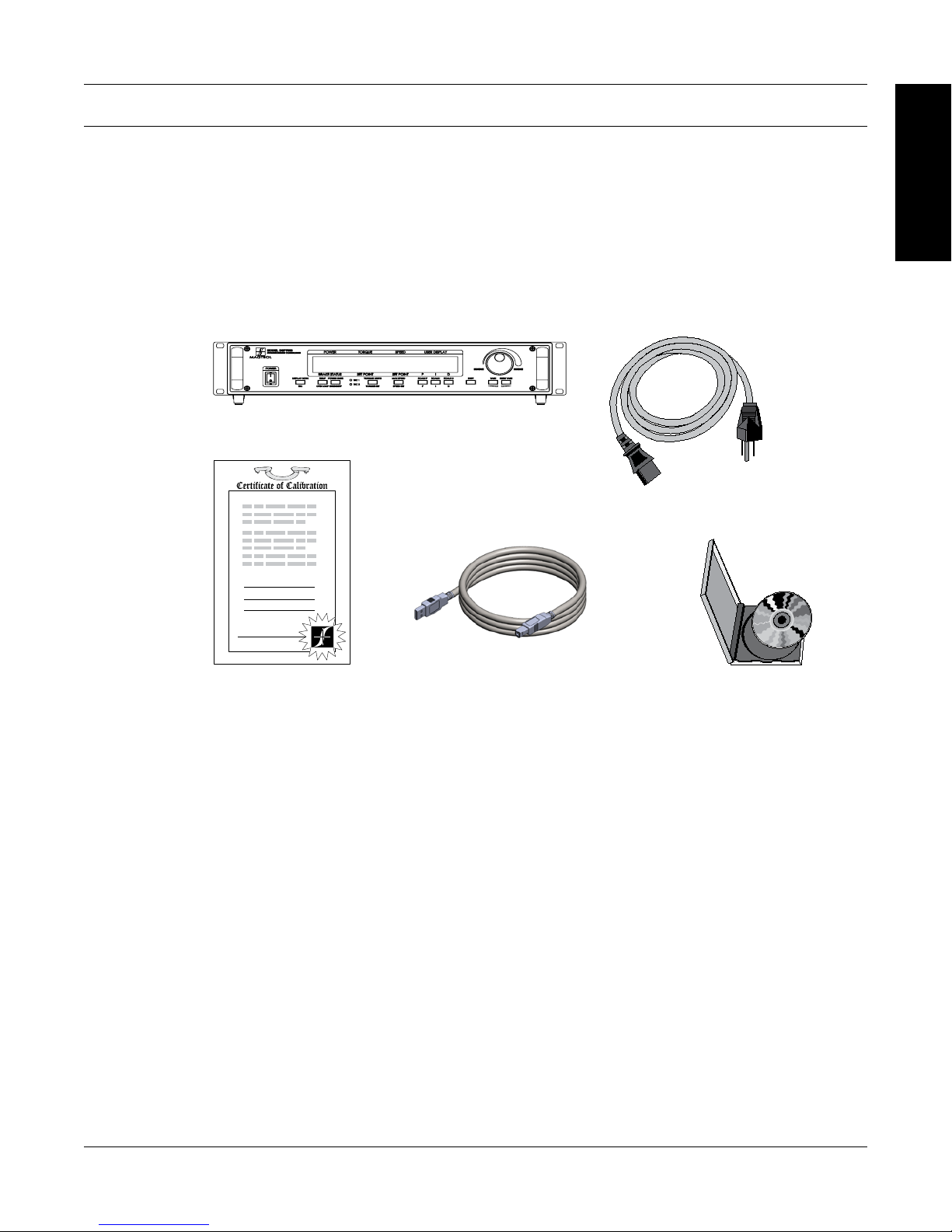
3. Make sure the carton contains the following:
DSP7000 Dynamometer Controller
INFORMATION
GENERAL
Line cord
Calibration Certificate
USB Cord
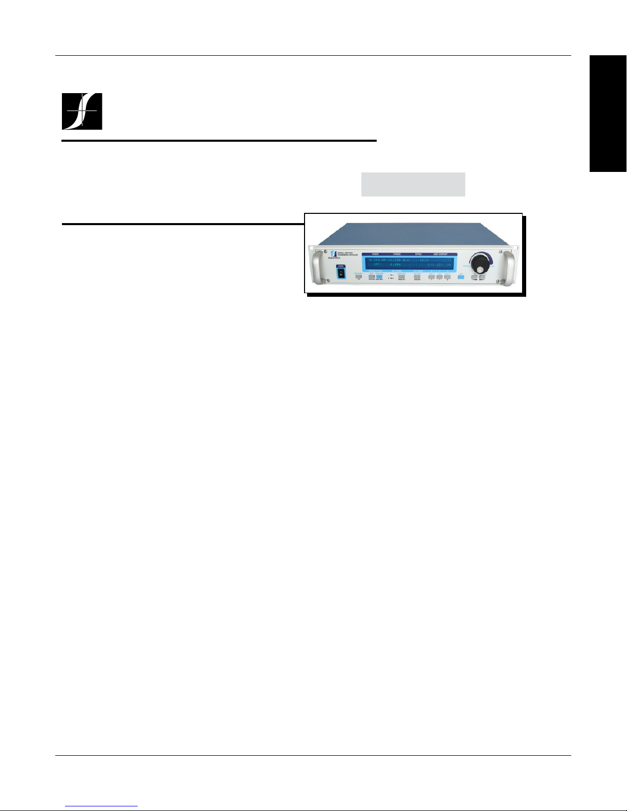
1.2 NEW FEATURES OF THE DSP7000
Magtrol’s new Model DSP7000 Dynamometer Controller is an upgraded version of the DSP6001,
providing superior motor testing capabilities by using state-of-the-art digital signal processing
technology. Designed for use with any Magtrol Hysteresis, Eddy-Current or Powder Brake
Dynamometer, Magtrol In-Line Torque Transducer or auxiliary instrumentation, the DSP7000 both
controls the dynamometer and provides digital readouts on the front panel. The features that make
the DSP7000 unique include:
• TwoChannels-Enablesunittosupportacombinationofuptotwotestinginstrumentswith
independent or tandem configurations.
• Built-InAlarm System - To caution the user when problems occur,there are automatic
electrical and temperature alarms programmed into the unit. Also inherent to the unit are
optional power, speed, torque, air flow, water flow and external input alarms that become
active when enabled by the user.
• Torque/SpeedAnalogOutputs-Abletointerfacewithadataacquisitionsystem
• DigitalFilter-Removesundesirednoisefromtorquesignals.
• Saving-Allowsusertosaveprogrammedvalueswithintheircongurations.
Magtrol User Manual CD-Rom
1
Magtrol Model DSP7000 Dynamometer ControllerChapter 1 – Introduction
DSP7000
Data Sheet
DSP7000 Series High-Speed Programmable
Dynamometer Controllers
MAGTROL
FEATURES
• DSP7001 Single Channel:Lowcostandeasytouse
• DSP7002 Dual Channel:Enablesthesupportof
twotestinginstrumentswithindependentortandem
configurationsandtwofullyindependentcontrolloops
• Built-in Alarm System: Forpower,speed,torque,
temperature,airflow,waterflow,electricaloverload
andexternalinputs
• High Speed Data Acquisition:Upto500torqueand
speedpointspersecondofbothchannelswithtime
stamp
• High Quality, Easy-to-Read Vacuum Fluorescent
Readout: Displaystorque,speed,power,auxiliaryand
PID(proportionalgain,integralandderivative)values
• Fast Full-Curve Data Acquisition:Free-runto
lockedrotorinseconds
• Speed & Torque Operating Modes:PIDsettingsfor
exceptionaldynamometercontrol
• Programmable Digital PID Values:Controlledand
storedviaM-TestSoftwareorcontrolledmanually
• Built-in Current-Regulated Supply: Forusewith
HysteresisDynamometerorbrakesupto1amp
• Adjustable Torque Units:English,MetricandSIare
standard
• Digital Filter: Removesundesirednoisefromtorque
signals
• Saving:Currentlyusedconfigurationcanbesavedand
recalledatpowerup
• Single or Multi-point Torque and Speed Stabilized
Testing: ViaM-TEST7.0Software
• ClosedBoxCalibration
• Rack Mounting:19"(482.6mm)withhandles
• Backwards Compatible:Compatiblewiththe
DSP6001(inDSP6001mode)
• HD5 dynamometers: Supported
• USB: Standard
• Low RPM:calculationfromangle(quadraturesignal)
andtimedesignedtocaptureRPM’saslowas.001
RPM
• Position Measurement:Twoquadraturedecoders
OPTIONS
• Interfaces:RS-232andIEEE-488
• I/Ocardaccessibleprogrammatically(LabVIEW™,
VisualC)
DESCRIPTION
Magtrol’s Model DSP7000 High Speed Programmable
Dynamometer Controller employs state-of-the-art Digital
SignalProcessingTechnologytoprovidesuperiormotortesting
capabilities.Designed for use with any Magtrol Hysteresis,
Eddy-Current or Powder Dynamometer, Magtrol In-Line
TorqueTransducerorauxiliaryinstrumentation,theDSP7000
can provide complete PC control via the USB or optional
IEEE-488orRS-232interface.Withup to 500 readings per
second,theDSP7000isideallysuitedforboththetestlaband
theproductionline.
APPLICATIONS
Inthe laboratory,theDSP7000’shighsamplerate provides
superior resolution for data acquisition and curve plotting.
Thisallowsforcapturingmoreusablemotortestdataduring
switching, breakdown and other transitional areas of the
motor test curve. For production and incoming inspection,
theDSP7000displaystorque,speedandpoweratall times,
allowingthe Controller tobeusedasamanualstand alone
unitoraspartofacompletePCsystem.
MOTOR TESTING SOFTWARE
Magtrol’sM-TEST 7 Software (sold separately) is a stateof-the-artmotortesting program forWindows®-baseddata
acquisition.Used with the Magtrol DSP7000 Controller,
Magtrol M-TEST 7 Software provides the control of any
MagtrolDynamometerandrunstestsequencesinamanner
bestsuited
totheoverallaccuracyandefficiencyoftheMagtrol
MotorTestSystem.ThedatathatisgeneratedbyMagtrol’s
MotorTestingSoftwarecanbestored,displayedandprinted
intabularorgraphicformats,andcanbeeasilyimportedinto
aspreadsheet.
WritteninLabVIEW™,M-TEST7hastheflexibilitytotest
amajority ofmotortypes inavarietyofways.Becauseof
LabVIEW’sversatility,obtainingdatafromothersources(e.g.
thermocouples),controllingmotorpowerandprovidingaudio/
visualindicatorsisrelativelyeasy.
Magtrol’sM-TEST7Softwareisidealforsimulatingloads,
cyclingtheunitundertestandmotorramping.Becauseitis
easytogatherdataandduplicatetests,thesoftwareisideal
foruseinengineeringlabs,productiontestingandincoming/
outgoinginspection.
DSP7001 - single channel
DSP7002 - dual channel
1.3 DATA SHEET
2
INFORMATION
GENERAL
Magtrol Model DSP7000 Dynamometer Controller
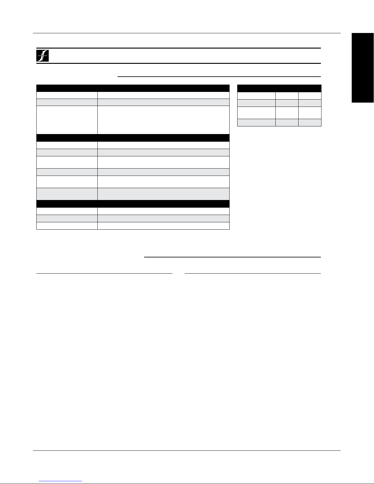
Specifications
sPecIFIcatIONs
Chapter 1 – Introduction
INFORMATION
GENERAL
DSP7000
MEASUREMENT CHARACTERISTICS
Maximum Torque 99,999 units
Maximum Speed 199,999 rpm
Speed: 0.01% of reading from 5 rpm to 200,000 rpm
Accuracy
ELECTRICAL CHARACTERISTICS
Voltage Requirements 85-264 VAC 50/60 Hz
Power Requirements 210 VA
Fuses (5 × 20 mm)
Max. Compliance Voltage 48 V DC, Brake Output
Max. Brake Output
Current
TSC1 and TSC2 User
Power Supplies
ENVIRONMENT
Operating Temperature 5 ºC to 40 ºC
Relative Humidity < 80%
Temperature Coefficient 0.004% of range/°C of 5 V DC for both channels
Torque: 2 volt range ± 0.05% of range (±1 mV)
10 volt range ± 0.05% of range (±5 mV)
Brake: IEC 1.25 A 250 V T
Main Power: IEC 2.5 A 250 V T
1 Amp, Calibrated that 100% OL = 1 Amp
24 Volt DC 450 mA (power supply fault protected)
5 Volt DC 200 mA (internal fuse at 500 mA)
(used on all HD Series other than HD5 Series)
(used on all except HD Series)
Optionalequipmentmaybefactoryinstalledorpurchasedseparatelyanduserinstalled.
OPtIONal equIPMeNt
DIMENSIONS
Width 19.0 in 483 mm
Height 3.5 in 89 mm
Depth
with handles
Weight 15.2 lb 6.9 kg
12.4 in
13.8 in
315 mm
351 mm
COMMUNICATIONS
RS-232 Interface
TheRS-232Interfaceprovidesbackwardscompatibilityfor
oldersystems.300,600,1200,2400,4800,9600,19200and
115200Baudratesaresupported.
GPIB IEEE-488 Interface
The GPIB IEEE-488 Interface provides standard GPIB
communications.
I/O CARD
• Torque/SpeedAnalogOutputs:Forinterfacewitha
dataacquistionsystem
• AnalogSignalsuchastachometercanberoutedtoPID
loop
• Externalalarminput
• Alarmrelaycontacts
• 2Relays
• 3Digitalinputs
• 2Digitaloutputs
• 2Analoginputs
• 2Analogoutputs
• 5Voltsavailabletouserfusedat500mA.Nominal200
mA
• AllI/OdatacanbeaccessedbyLabVIEW™
3
Specifications
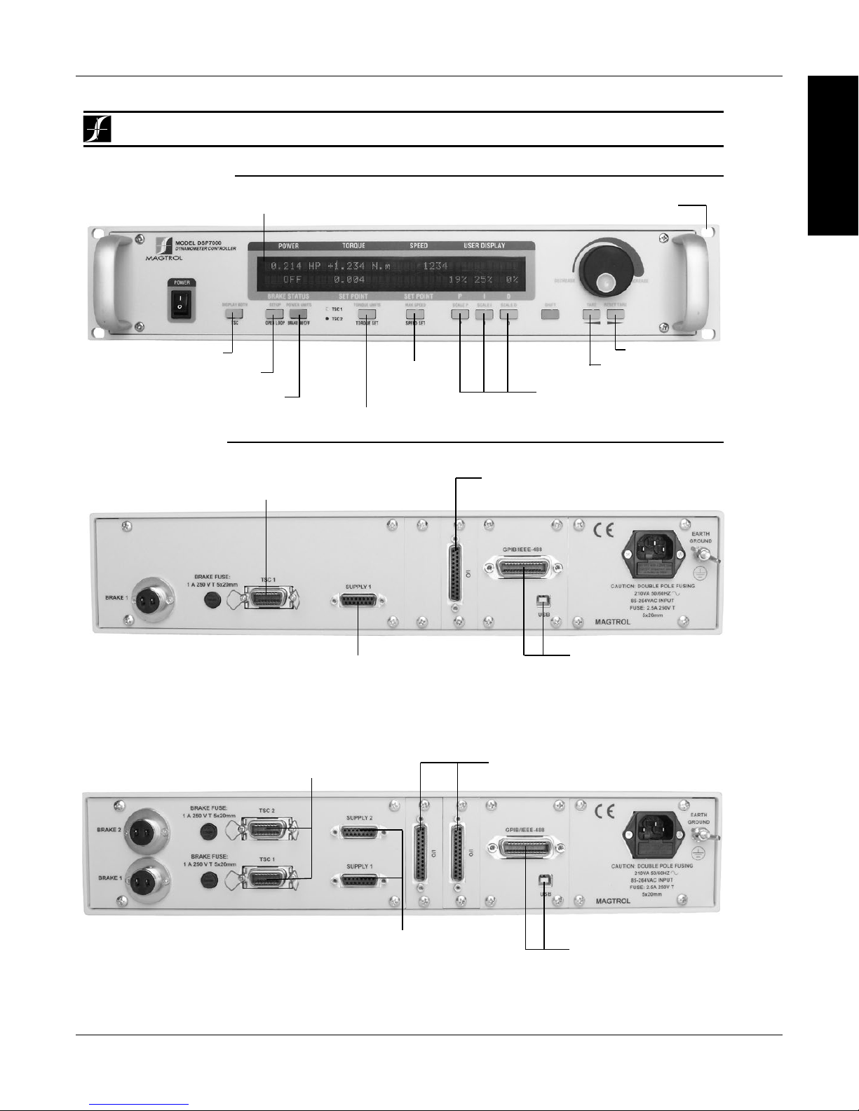
FrONt Pa Nel
Displays Torque, Speed, Power
and PID Values
•
•
• • • • • • •
Magtrol Model DSP7000 Dynamometer ControllerChapter 1 – Introduction
INFORMATION
GENERAL
DSP7000
Ready for Rack Mounting
•
• •
Select Display Format
Setup Menu/Open Loop Mode
Set Desired Power
Units/Brake on/off
rear PaNels
For use with any Magtrol Dynamometer
(Hysteresis, Eddy-Current, Powder Brake),
Magtrol Torque Transducer
For use with any Magtrol Dynamometer
(Hysteresis, Eddy-Current, Powder Brake),
Magtrol Torque Transducer
Speed Control/
Set Point Speed
Set Desired Torque Units/Set Point Torque
•
•
Connector for Model
DES Power Supplies
(for WB/PB and HD 825 Dynamometers only)
•
DSP7001 Rear Panel
Reset Tare
Tare
PID Scale/Adjustable PID
(Proportional Gain,
Integral and Derivative)
Optional I/O Card
•
•
USB (standard) and Optional
GPIB/IEEE-488 Interface
or RS-232 Interface for
Connection to PC
(GPIB Shown)
Optional I/O Card 1 and I/O Card 2
•
•
(for WB/PB and HD 825 Dynamometers only)
•
•
Connectors for Models
DES Power Supplies
DSP7002 Rear Panel
• •
4
•
•
USB (standard) and Optional
GPIB/IEEE-488 Interface
or RS-232 Interface for
Connection to PC
(GPIB Shown)
Magtrol Model DSP7000 Dynamometer Controller
DSP7000
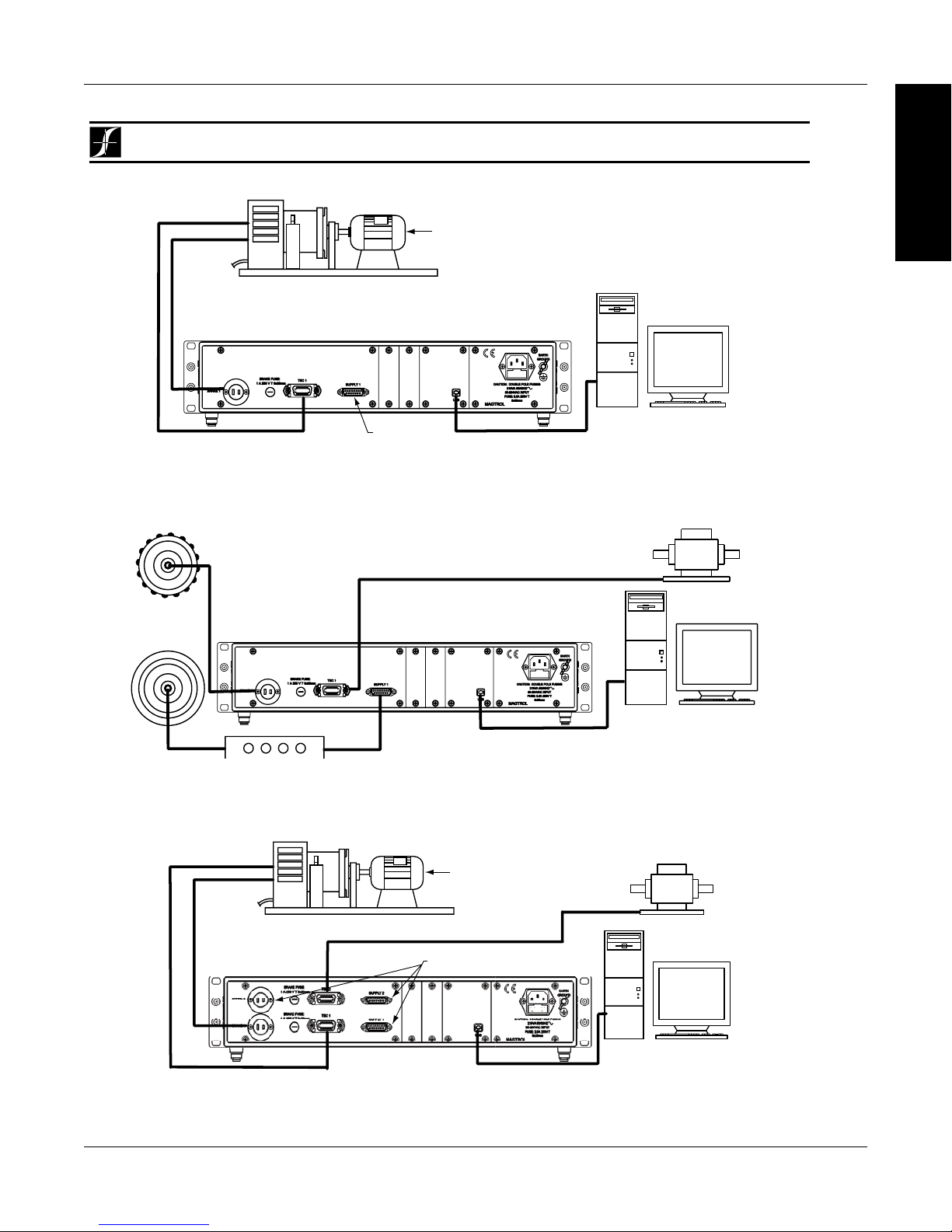
System Configurations
DSP7002 Connected to Hysteresis Dynamometer with In-Line Torque Transducer
Motor
Under
Test
TM Torque Transducer
AC Mains
Hysteresis Dynamometer (HD)
DSP
7002
DYNAMOMETER
CONTROLLER
No Connection
USB
PC
M-TEST
AC Mains
Motor
Under
Test
Hysteresis Dynamometer (HD)
DSP
7001
DYNAMOMETER
CONTROLLER
USB
PC
M-TEST
No Connection
DSP7001 Connected to Hysteresis Dynamometer
Torque Transducer
(TM)
DES Power Supply
Hysteresis
Brake
(<1 Amp)
Hysteresis Brake
(<5 Amp)/
Eddy-Current/
Powder Brake
OR
DSP
7001
DYNAMOMETER
CONTROLLER
USB
M-TEST
PC
DSP7001 Connected to a Hysteresis or Eddy-Current/Powder Brake with In-Line Torque Transducer
Chapter 1 – Introduction
INFORMATION
GENERAL
5
Magtrol Model DSP7000 Dynamometer ControllerChapter 1 – Introduction
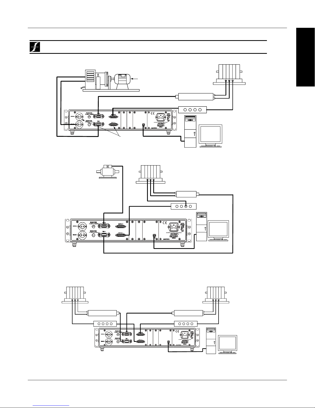
DSP7000
System Configurations
DSP7002 Connected to Eddy-Current or Powder Brake Dynamometer (WB/PB)
with In-Line Torque Transducer
TM Torque
Transducer
USB
PC
M-TEST
DSP7002 Dynamometer Controller
Excitation
Torque
TSC 401
Torque-Speed
Conditioner
DES Power Supply
Speed
Eddy-Current (WB)
OR Powder Brake (PB)
Dynamometer
DSP7002 Connected to Hysteresis Dynamometer and Eddy-Current or Powder Brake Dynamometer
No Connection
Eddy-Current (WB)
OR Powder Brake (PB)
Dynamometer
AC Mains
Hysteresis Dynamometer (HD)
Excitation
Torque
Speed
TSC 401
Torque-Speed
Conditioner
DES Power Supply
Motor
Under
Test
USB
PC
M-TEST
DSP7002
DYNAMOMETER
CONTROLLER
DSP7002 Connected to 2 Eddy-Current or Powder Brake Dynamometers (Independent Setup)
Eddy-Current (WB)
OR Powder Brake (PB)
Dynamometer
Excitation
Torque
Speed
TSC 401 Torque-Speed
Conditioner
DES Power Supply
Eddy-Current (WB)
OR Powder Brake (PB)
Dynamometer
Excitation
Torque
Speed
TSC 401 Torque-Speed
Conditioner
DES 31x Power Supply
DSP
7002
DYNAMOMETER CONTROLLER
USB
PC
M-TEST
INFORMATION
GENERAL
6
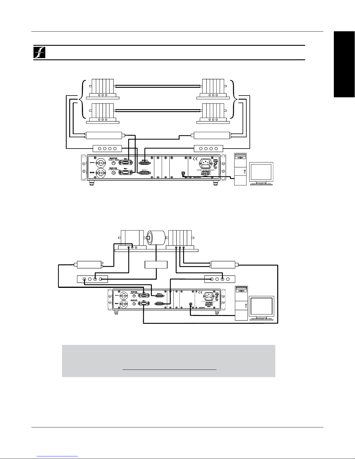
Magtrol Model DSP7000 Dynamometer Controller
Powder Brake
Eddy-Current Brake
Eddy-Current (WB)
Eddy-Current (WB)
System Configurations
Chapter 1 – Introduction
INFORMATION
GENERAL
DSP7000
Dynamometer
Dynamometer
OR
DSP
7002
Powder Brake (PB)
Dynamometer
Torque-Speed Conditioner
DES Power Supply
TSC 401
Speed
Torque
Excitation
PC
M-TEST
USB
Torque-Speed Conditioner
Speed
Torque
Excitation
DES Power Supply
TSC 401
Powder Brake (PB)
Dynamometer
DYNAMOMETER CONTROLLER
DSP7002 Connected to 2 Eddy-Current or 2 Powder Brake Dynamometers (Tandem Setup)
Dynamometer (PB)
TSC 401
Torque/Speed
Conditioner
DES Power Supply
Torque
Excitation
Clutch
(EK)
Transformer
Dynamometer (WB)
Speed
Torque
Excitation
TSC 401
Torque-Speed
Conditioner
DES Power Supply
DSP
7002
Dynamometer
Controller
DSP7002 Connected to Eddy-Current and Powder Brake Dynamometer (Tandem Setup)
TheUSBDriverrequiredforcommunicationbetweenthePCandDSP7000isavailablefor
downloadatMagtrol’swebsite:
www.magtrol.com/support/downloads.html
7
PC
M-TEST
USB
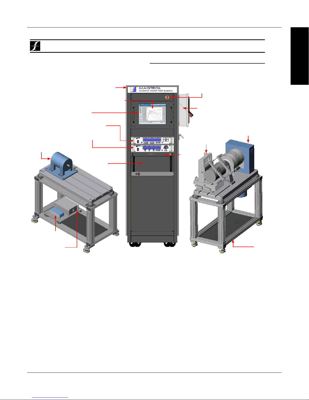
Magtrol Model DSP7000 Dynamometer ControllerChapter 1 – Introduction
DSP7000
custOM MOtOr test systeM
TheDSPcanbeincorporatedintoaCustomizedMotorTestSystem.ThesePCbased,turn-keysystemsarecustomdesigned
andbuilttomeetspecificuserrequirements.
System Configurations
heavy-duty equipment rack
M-TEST Motor Testing Software
WB Eddy-Current
Dynamometer
DES Power Supply
TSC Torque Signal
Conditioner
AMF Adjustable
Motor Fixture
Dynamometer
Table
HD Hysteresis
Dynamometer
DSP7000 Dynamometer
Controller
6530 Power Analyzer
keyboard
drawer
side panel connectors allow
for easy hook-up
space for rackmounted
third-party power supply
and computer
LCD monitor
emergency stop button
INFORMATION
GENERAL
8

Magtrol Model DSP7000 Dynamometer Controller
Ordering Information
Chapter 1 – Introduction
DSP7000
ORDERING INFORMATION
DSP7001 High-Speed Programmable Dynamometer Controller - single channel
DSP7002 High-Speed Programmable Dynamometer Controller - dual channel
Model Number: DSP700X – X – X
CHANNEL TYPE
• Single Channel 1
• Dual Channel 2
COMMUNICATION OPTIONS
• none (standard USB) 0
• USB port and GPIB 1
• USB port and RS-232 2
I/O Options
• None (standard) 0
• I/O card in slot1 (7001) 1
• I/O card in slot 1 and 2 (7002) 3
SYSTEM OPTIONS AND ACCESSORIES
CATEGORY DESCRIPTION MODEL / PART #
Hysteresis Dynamometers HD series
TESTING
DEVICES
POWER
ANALYZERS
SOFTWARE
POWER
SUPPLIES
MISC.
CARDS &
CABLES
Due to the continual development of our products, we reserve the right to modify specifications without forewarning.
Eddy-Current Dynamometers WB series
Powder Brake Dynamometers PB series
In-Line Torque Transducers TM/TMHS/TMB series
High-Speed Single-Phase Power Analyzer
High-Speed Three-Phase Power Analyzer 6530
M-TEST 7.0 Motor Testing Software SW-M-TEST7.0-WE
EM-TEST 2.0 Endurance Motor Testing Software SW-EM-TEST2.0-WE
Closed-Loop Speed Control/Power Supply 6100
Power Supply 5200
Current-Regulated Power Supply 5210
Power Amplifier (required for HD-825 Dynamometer only) 5241
Power Supply for WB & PB Dynamometers DES 410 & DES 411
Torque/Speed Conditioner
(required for connecting WB/PB Series Dynamometers to DSP6001)
Temperature Testing Hardware HW-TTEST
GPIB Interface Card (PCI) 73M023
GPIB Cable, 1 meter 88M047
GPIB Cable, 2 meters 88M048
Torque Transducer Connector Cable ER 113/01
DSP7000 GPIB Card
DSP7000 RS-232 Card 006578
DSP7000 I/O Card 006577
6510e
TSC 401
006579
INFORMATION
GENERAL
9
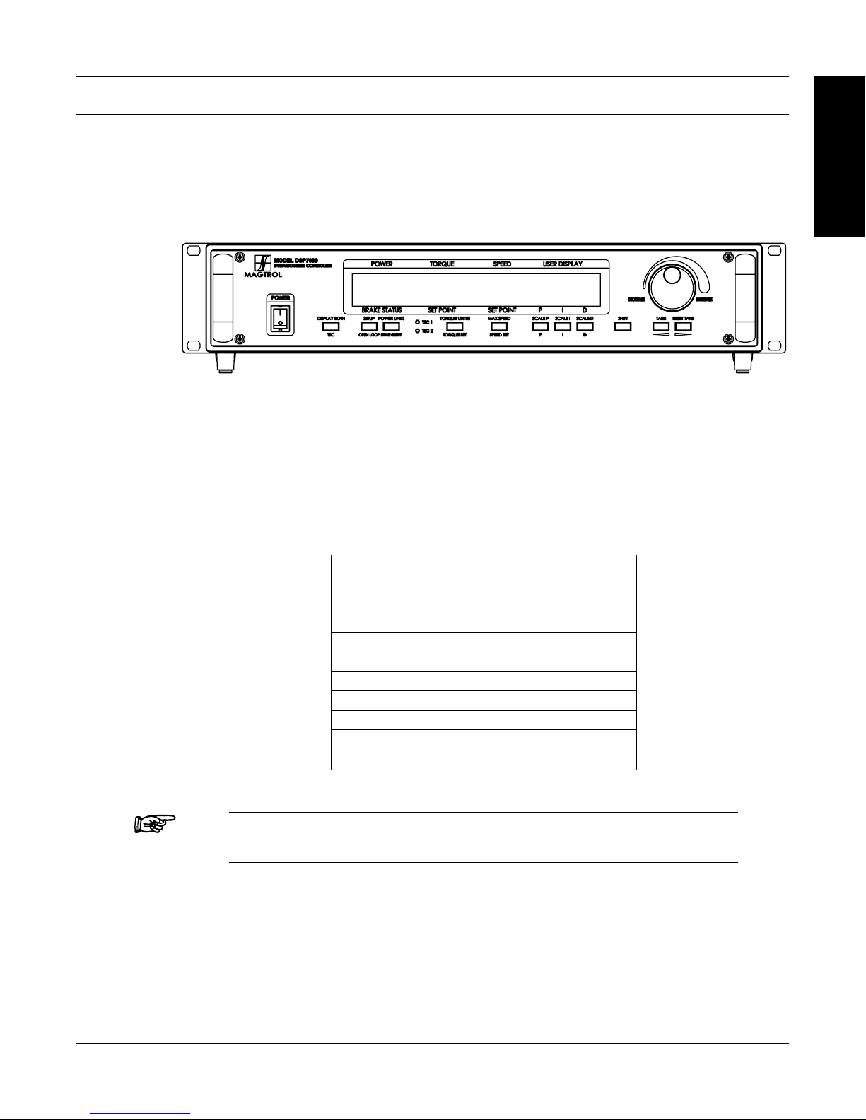
2. Controls
2.1 FRONT PANEL
The front panel provides a power switch, eleven control buttons, a Decrease/Increase Dial, and
Vacuum Fluorescent Display (VFD).
Figure 2–1 Front Panel
2.2 FRONT PANEL CONTROLS AND BUTTONS
The front panel controls and buttons, from left to right, are:
• Powerswitch
• Tendouble-functioncontrolbutton:
INFORMATION
GENERAL
Primary Function Secondary Function
TSC DISPLAY BOTH
OPEN LOOP SETUP
BRAKE ON/OFF POWER UNITS
TORQUE SET TORQUE UNITS
SPEED SET MAX SPEED
P SCALE P
I SCALE I
D SCALE D
TARE
RESET TARE
Note: The TSC/DISPLAY BOTH button has no function on the DSP7001
Programmable Controller.
• Onesingle-functioncontrolbutton:
• SHIFT(enablessavingfunctionandsecondaryfunctionsprintedinblueabovecontrol
buttons)
• Decrease/IncreaseDial(decreasesorincreasestheselectedparameter)
10
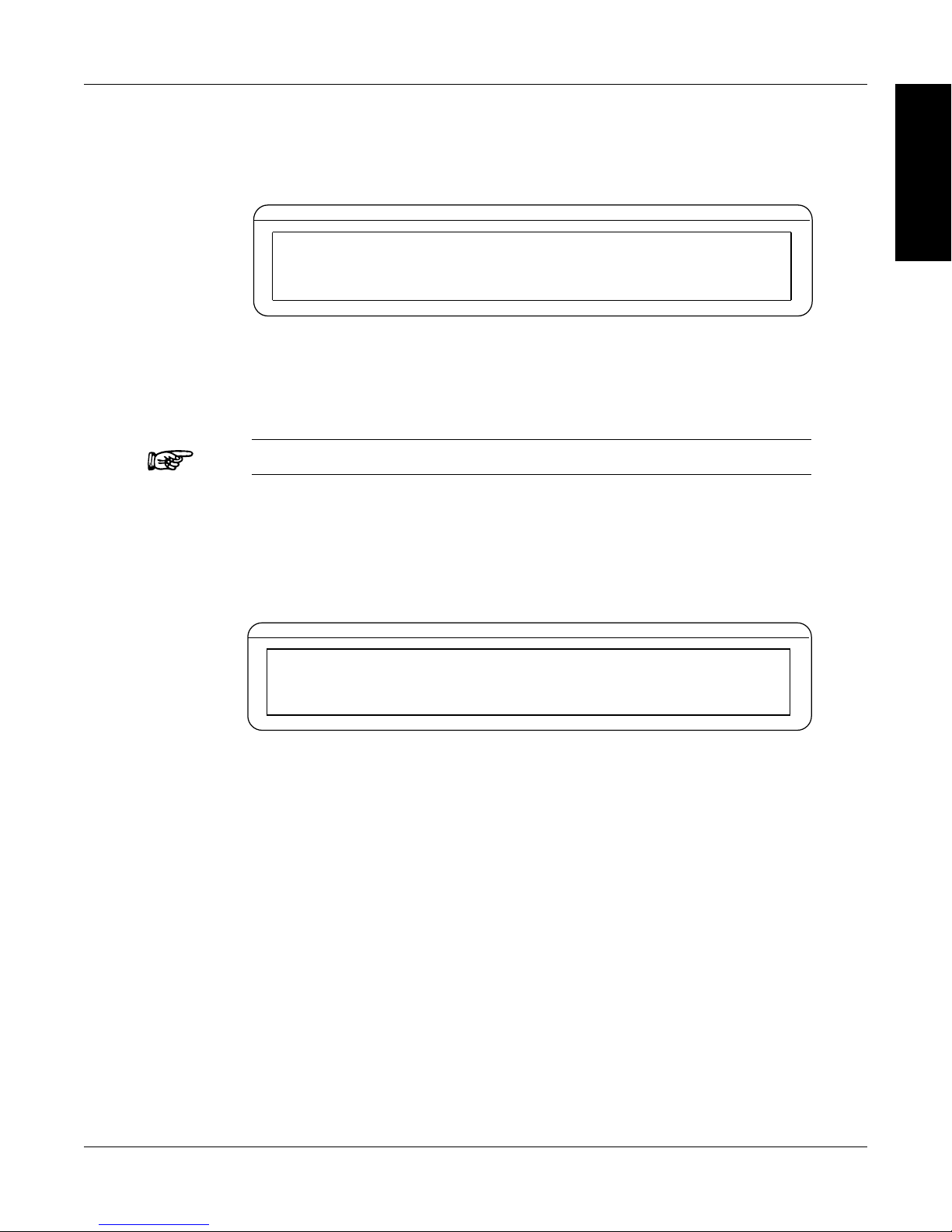
Magtrol Model DSP7000 Dynamometer Controller
POWER
BRAKE STATUS SET POINT SET POINT PID
TORQUE SPEED USER DISPLAY
0.000 W
OFF
0.000 OZ.IN
0000
0%
0% 0%
0 SHIFT
POWER
TORQUE SPEED USER DISPLAY
Chapter 2 – Controls
2.2.1 Enabling SEcondary FunctionS
To enable the secondary function of the double-function control buttons:
1. Press the blue SHIFT button and release it. The word “SHIFT” appears in the display:
Figure 2–2 Secondary Function Menu
2. Press any control button to enable the function shown in blue letters above the button.
3. Press the SHIFT button again to exit the secondary function and return to main menu.
Note: If the brake status is ON, the SHIFT button will be ignored.
2.2.2
Enabling Saving Function
To save all current programmed settings:
1. Press the SHIFT button two times. The word “SAVING” will appear in the display, as shown
in Figure 2–3 Saving Function Menu.
INFORMATION
GENERAL
0.000 W
OFF
BRAKE STATUS SET POINT SET POINT PID
2. After a few seconds, the menu will automatically return to the main menu display and all
configurations of the unit will be saved into a non-volatile memory.
0.000 OZ.IN
0000
Figure 2–3 Saving Function Menu
0 SAVING
0%
0% 0%
11

Magtrol Model DSP7000 Dynamometer ControllerChapter 2 – Controls
2.2.3 How to uSE Front PanEl controlS and buttonS
2.2.3.1 Controls/Single-Function Buttons
Button To Use Function
POWER Press I to turn power ON Press O
to turn power OFF.
SHIFT Press this button and release; then
press desired control button.
Press this button two times and
release.
DECREASE /
INCREASE DIAL
Turn clockwise or
counterclockwise.
INFORMATION
GENERAL
Turns power ON or OFF.
Enables the function written in blue
above control button.
Saves current conguration of unit
to non-volatile memory.
Increases or decreases the
parameter selected.
12

Magtrol Model DSP7000 Dynamometer Controller
Chapter 2 – Controls
2.2.3.2 Double-Function Buttons
Button To Use Function
DISPLAY BOTH Press SHIFT and release; then
press this button.
TSC Press this button Switches between TSC1 and
SETUP Press SHIFT and release; then
press this button.
OPEN LOOP Press this button Enables Open Loop mode (if brake
POWER UNITS Press SHIFT and release; then
press this button.
BRAKE ON/OFF Press this button. Turns brake ON or OFF.
TORQUE UNITS Press SHIFT and release; then
press this button.
TORQUE SET Press this button. Enables adjustment of set point for
MAX SPEED Press SHIFT and release; then
press this button.
SPEED SET Press this button. Enables adjustment of set point for
SCALE P Press SHIFT and release; then
press this button.
SCALE I Press SHIFT and release; then
press this button.
SCALE D Press SHIFT and release; then
press this button.
TARE/LEFT
RESET TARE/
RIGHT
Press SHIFT and release; then
press this button.
Press SHIFT and release; then
press this button.
INFORMATION
GENERAL
Displays both TSC1 and TSC2
measurments.
TSC2 setup.
Displays setup menu for
dynamometer, autotune, I/O,
system, and user.
is off).
Sets desired unit of power. Press
UP or DOWN button to see
options. Press SHIFT to enable
option.
Sets desired unit of measure.
Press UP or DOWN button
to see options. Press SHIFT to
enable option.
torque loading.
Sets the speed range of the
Controller.
speed loading.
Turns auxiliary/torque transducer
display ON or OFF. Enables
adjustment of scale factors for
torque and speed DAC’S.
Adjusts GPIB primary address and
RS-232 baud rate. Also adjusts
display contrast.
Provides options to set maximum
power, dynamometer settings
(input units, maximum torque and
scale factor), speed encoders and
alarms.
2.3 VACUUM FLUORESCENT DISPLAY (VFD)
The VFD provides information about the control functions, the motor under test, and an auxiliary
input device or In-Line Torque Transducer (if connected). The displays, from left to right, are:
13

Top Row Bottom Row
POWER BRAKE STATUS (ON or OFF)
TORQUE SET POINT (TORQUE)
SPEED SET POINT (SPEED)
USER DISPLAY
2.3.1 contraSt SEttingS
The DSP7000 is shipped with the Contrast Setting at zero (lowest) in order to prolong display life.
If it is necessary to increase the Contrast for improved readability, execute the following steps:
1. Press SHIFT.
2. Press SETUP button.
3. Select SYSTEM
3. Select CONTR until desired brightness is reached.
4. Press SHIFT 2 times to return to main menu.
Note: Make sure the lowest possible setting is used to achieve desired
Magtrol Model DSP7000 Dynamometer ControllerChapter 2 – Controls
INFORMATION
GENERAL
P
I
D
result. Using a setting higher than necessary may cause display
segments to burn-in over a period of time, resulting in uneven
illumination from segment to segment.
2.3.2
StatuS diSPlay MESSagES
Message Meaning
SHIFT Shift button was pressed.
MAX SPEED Maximum motor RPM.
UNITS Torque unit of measurement.
REMOTE Remote control via PC enabled.
RAMP DOWN Decrease motor speed by increasing load on motor.
RAMP UP Increase motor speed by decreasing load on motor.
SAVING Saves current conguration of unit to non-volatlie memory.
RAMP DU Decrease motor speed and then increase motor speed
POWER UNITS
UNITS Torque units
14
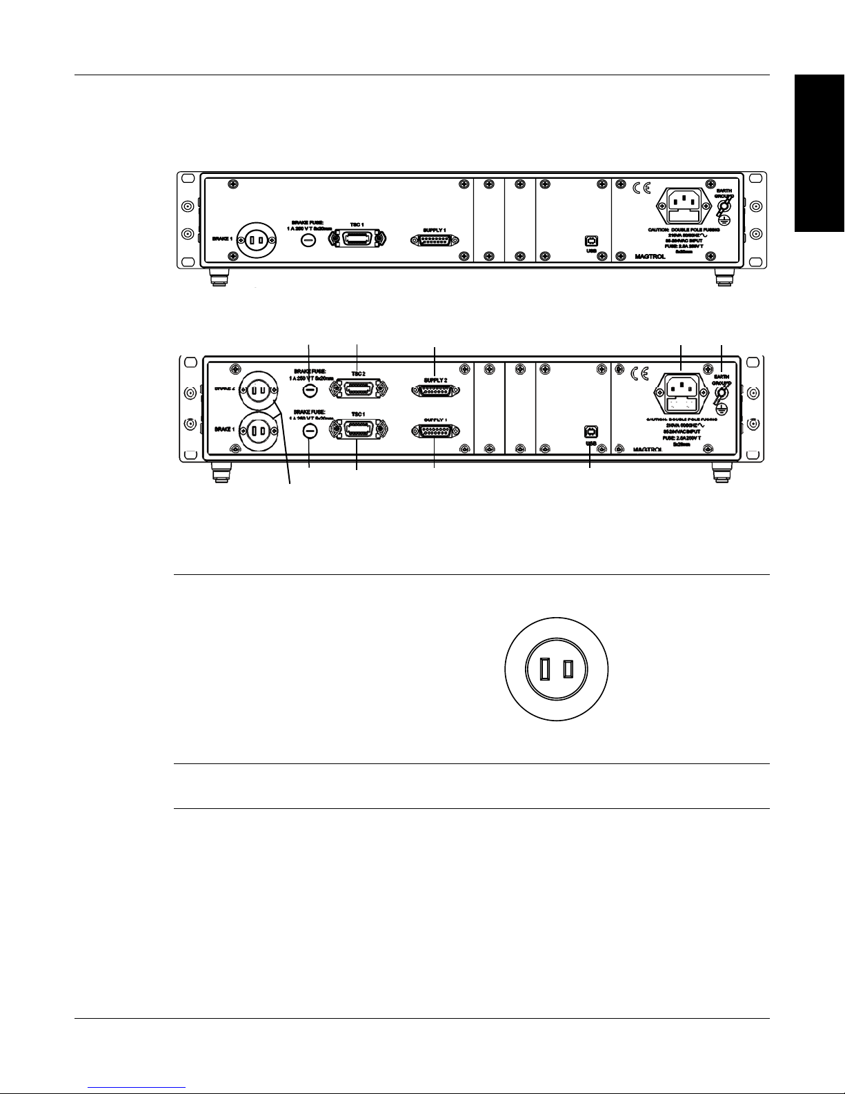
Magtrol Model DSP7000 Dynamometer Controller
Chapter 2 – Controls
2.4 REAR PANEL
The rear panel provides connectors and receptacles for connecting to appropriate equipment.
Figure 2–4 DSP7001 Rear Panel
Figure 2–5 DSP7002 Rear Panel
INFORMATION
GENERAL
2.4.1 rEar PanEl inPutS and outPutS
BRAKE 1/BRAKE 2 Connect dynamometer brake cable here.
BRAKE
Contains brake fuse (1A 250 VT 5 x 20 mm)
FUSE
Current
Regulation
-
Figure 2–6 Dynamometer Brake Output
+
+ 48 V
(fused)
15

Magtrol Model DSP7000 Dynamometer ControllerChapter 2 – Controls
1. FLOW/CLUTCH
2. TA CH. B
3. +24 VDC
4. +24 VDC COM
5. -24 VDC COM
6. -24 VDC
7. +5.0 VDC
8. +5.0 VDC COM
9. D.P. A
10. TACH. A
11. NC
12. D.P. B
13. TORQUE COMMON
14. TORQUE SIGNAL
1. SHIELD (EARTH)
2. ELECTRICAL ALARM
3. SUPPLY 1-N/C / SUPPLY 2-CLUTCH
4. SUPPLY +24VDC
5. N/C
6. +24 VDC COM
7. CURRENT SET POINT (SIGNAL)
8. WATER FLOW ALARM
9. N/C
10. TEMPERATURE ALARM
11. STAND-BY
12. N/C
13. +24 VDC COM
14. CURRENT SET POINT (ANALOG OV)
15. N/C
TSC1/TSC2 Connect torque signal cable here.
Figure 2–7 TSC1/TSC2 Connector
SUPPLY 1/SUPPLY 2 Connect WB/PB DES supply for TSC1/TSC2 here.
INFORMATION
GENERAL
USB Connect PC USB cable here.
POWER Attach power cord here.
EARTH GROUND Attach earth ground here.
Figure 2–8 Supply 1/Supply 2 Connector
Figure 2–9 USB Connector
16

Magtrol Model DSP7000 Dynamometer Controller
1.
Analog
out
OR user
2.
Analog Speed
out
OR user
3. AIN1+
4. AIN2+
5. 5
6. Ex
7. DI
8. DI
9. DOUT1
10. Relay1 NO
11. Relay1 NC
12. Relay2 NO
13. Relay2 NC
ommon
ommon
ommon
2.4.2 oPtional io
1. IO Card 1 and IO Card 2
Chapter 2 – Controls
INFORMATION
GENERAL
DAC 1
Torque
DAC 1
DAC 2
DAC 2
Volts
ternal Alarm
1
2
14. DAC 1 common
15. DAC 2 common
16. AIN1-
17. AIN2-
18. 5 Volts C
19. External Alarm
Common
20. 5 Volts C
21. 5 Volts C
22. DOUT2
23. Relay1 Common
24. 5 Volts Common
25. Relay2 Common
Figure 2–10 I/O Interface Card 1 and Card 2
17

Magtrol Model DSP7000 Dynamometer ControllerChapter 2 – Controls
12. SHIELD
11. ATN
10. SRQ
9. IFC
8. NDAC
7. NRFD
6. DAV
5. E01
4. D4
3. D3
2. D2
1. D1
24. SIGNAL GROUND
23. ATN-COM
22. SRQ-COM
21. IFC-COM
20. NDAC-COM
19. NRFD-COM
18. DAV-COM
17. REN
16. D8
15. D7
14. D6
13. D5
9. RI
2.4.3 oPtional gPib
2.4.4 oPtional rS-232
INFORMATION
GENERAL
Figure 2–11 GPIB Interface
1. DCD
2. TX
3. RX
4. DTR
5. GND
6. DSR
7. RTS
8. CTS
Figure 2–12 RS-232 Interface
18

3. Installation/Configuration
POWER
TORQUE SPEED USER DISPLAY
POWER
TORQUE SPEED USER DISPLAY
POWER
TORQUE SPEED USER DISPLAY
Note: Before installing the DSP7000, you should become familiar with
the front and rear panels, as outlined in Chapter 2–Controls.
3.1 POWERING UP THE DSP7000
3.1.1
WARNING! TO REDUCE THE RISK OF ELECTRIC SHOCK, MAKE
SURE THE DSP7000 IS EARTH GROUNDED BEFORE
STARTING!
Self-TeST
After turning the power on to the DSP7000, the display panel will show the message “SERIAL KEY
PAD REV X.X” while the DSP7000 is downloading the program.
SERIAL KEY PAD REV X.X
BRAKE STATUS SET POINT SET POINT PID
Figure 3–1 Program Download Display
When the program download is complete, the message “MAGTROL MODEL DSP700X, FW
REV:XX, FPGA REV:XX” appears.
SETUP
FW REV:XX
BRAKE STATUS SET POINT SET POINT PID
If the alarms are disabled, the following display message will appear at this time.
BRAKE STATUS SET POINT SET POINT PID
To activate the alarms, refer to Chapter 6 - Alarm System.
MAGTROL
MODEL DSP700X
Figure 3–2 Revision Display
FPGA REV:XX
WARNING ALL ALARMS ARE DISABLED
ON TSCX
Figure 3-3 Alarm Warning Display
19

3.1.2 Main Menu
POWER
TORQUE SPEED USER DISPLAY
When the DSP7000 is completely powered up and ready for use, the main menu will appear on the
display.
Magtrol Model DSP7000 Dynamometer ControllerChapter 3 – Installation/Configuration
0.000 W
0.000 OZ.IN
OFF
BRAKE STATUS SET POINT SET POINT PID
Figure 3–4 Main Menu
3.2 INSTRUMENTATION SETUP (TORQUE)
The DSP7000 has the ability to support a combination of up to two testing instruments with
independent or tandem configurations.
Note: In the TSC1 (WB/PB) and TSC2 (WB/PB) combination, the
instruments can be configured independently or as a tandem unit.
The setup of your unit will depend on which option you choose. The following sections will illustrate
and outline the hardware connection and software configurations needed to begin your testing, based
on your selection. For additional reference, see Appendix C: Front Panel/Display Menu Flow Charts.
Each channel of the DSP7000 can support the following dynamometers:
0000
0
0%
0% 0%
SETUP
TSC 1/TSC 2
HD
WB
PB
TM/TF
HD5
20

Magtrol Model DSP7000 Dynamometer Controller
POWER
BRAKE STATUS SET POINT SET POINT PID
TORQUE SPEED USER DISPLAY
DYNO
I/OSYSTEM
USER
POWER
TORQUE SPEED USER DISPLAY
3.2.1 DynaMoMeTer ConfiguraTion Menu
To reach the dynamometer configuration menu:
1. Turn on DSP7000 power. See Section 3.1 – Powering Up the DSP7000.
2. Press SHIFT. The word “SHIFT” will appear in the display.
3. Press the SETUP button. The display should appear as follows:
4. Select DYNO. The display should appear as follows:
Chapter 3 – Installation/Configuration
SETUP
Figure 3–5 Setup Menu
MAXPOWER
BRAKE STATUS SET POINT SET POINT PID
5. Select DYNAMOMETER. The display should appear as follows:
POWER
DYNAMOMETER
Figure 3-6 Dyno Setup Menu
TORQUE SPEED USER DISPLAY
TSCX
HD
BRAKE STATUS SET POINT SET POINT PID
Figure 3–7 Dynamometer Configuration Menu
6. Pressing the POWER UNITS button allows selection of the preferred testing device (HD,
WB, PB or HD5) for TSC1. Pressing the MAX SPEED button allows selection of the input
units (N·m, oz·in, oz·ft, lb·in, lb·ft, g·cm, kg·cm, mN·m, cN·m). Pressing SCALE I allows
selection of a filter if desired. Refer to the remainder of this chapter for more detailed
instructions on setup and configuration of the different testing devices.
ENCODERS
ALARMS
INPUT UNITS FILTER
N.m
NONE
NOTE: For information on Filters, see Section 3.3 – Torque Filter Setup.
21

3.2.2 HySTereSiS DynaMoMeTer SeTup
Hysteresis Dynamometer (HD)
POWER
BRAKE STATUS SET POINT SET POINT PID
TORQUE SPEED USER DISPLAY
TSC1 MAX TORQUE
XXXX
3.2.2.1 Hardware Connection
AC Mains
Magtrol Model DSP7000 Dynamometer ControllerChapter 3 – Installation/Configuration
Motor
Under
Test
DSP7001
DYNAMOMETER
CONTROLLER
3.2.2.2 Software Conguration
1. Turn on the DSP7000 and proceed to the dynamometer configuration menu. See Section
3.2.1 – Dynamometer Configuration Menu.
2. Press POWER UNITS until HD is reached.
3. Press MAX SPEED until the desired input unit for TSC.
4. Press SCALE I to add a filter if desired.
5. Press SHIFT. The display should appear as follows:
PC
SETUP
M-TEST
USB
No Connection
Figure 3–8 Hysteresis Dynamometer Setup
Figure 3–9 Hysteresis Setup Menu
6. Press TORQUE UNITS button and use and buttons and Decrease/Increase dial to set
desired max torque for TSC1.
7. Press SHIFT 3 times to complete the initial setup and return to the main menu.
22

Magtrol Model DSP7000 Dynamometer Controller
Hysteresis Dynamometer (HD)
POWER
BRAKE STATUS SET POINT SET POINT PID
TORQUE SPEED USER DISPLAY
TSC2 MAX TORQUE NOMINAL SPEED
X.XXX XXXX.X
3.2.3 HySTereSiS DynaMoMeTer wiTH TranSDuCer SeTup
3.2.3.1 Hardware Connection
Chapter 3 – Installation/Configuration
AC Mains
DSP7002
DYNAMOMETER
CONTROLLER
Figure 3–10 Hysteresis Dynamometer with Torque Transducer Setup
3.2.3.2 Software Conguration
1. Turn on the DSP7000. Set up TSC1 as described in section 3.2.2 - Hysteresis Dynamometer
Setup. Press TSC to switch to TSC2 setup and proceed to the dynamometer configuration
menu. See Section 3.2.1 – Dynamometer Configuration Menu.
2. Press POWER UNITS until TM/TF is reached for TSC2.
3. Press TORQUE UNITS until HB is reached.
4. Press MAX SPEED button and use and buttons and Decrease/Increase dial to set
desired scale factor for TSC2.
5. Press SCALE I to add a filter if desired.
6. Press SHIFT. The display should appear as follows:
Motor
Under
Test
No Connection
TM Torque Transducer
SETUP
PC
M-TEST
USB
Figure 3–11 Torque Transducer Setup Menu
7. Press the TORQUE UNITS button and use and buttons and Decrease/Increase dial to
set desired max torque. Press the SCALE P button and use and buttons and Decrease/
Increase dial to set desired nominal speed.
8. Press SHIFT 3 times to return to the main menu.
23

Magtrol Model DSP7000 Dynamometer ControllerChapter 3 – Installation/Configuration
Eddy-Current (WB)
Hysteresis Dynamometer (HD)
POWER
TORQUE SPEED USER DISPLAY
3.2.4 HySTereSiS DynaMoMeTer wiTH eDDy-CurrenT or powDer Brake SeTup
3.2.4.1 Hardware Connection
AC Mains
DSP7002
DYNAMOMETER
CONTROLLER
Figure 3–12 Hysteresis Dynamometer with Eddy-Current or Powder Brake Setup
3.2.4.2 Software Conguration
1. Turn on the DSP7000. Set up TSC1 as described in section 3.2.2 - Hysteresis Dynamometer
Setup. Press TSC to swtich to TSC2 setup and proceed to the dynamometer configuration
menu. See Section 3.2.1 – Dynamometer Configuration Menu.
2. Press POWER UNITS until WB or PB is reached.
3. Press MAX SPEED button and use and buttons and Decrease/Increase dial to set
desired scale factor for TSC2.
4. Press SCALE I to add a filter if desired.
5.a. If using an Eddy Current Dynamometer, press SHIFT. The display should appear as follows:
No Connection
Motor
Under
Test
OR Powder Brake (PB)
Dynamometer
TSC 401
Torque-Speed
Conditioner
DES Power Supply
PC
M-TEST
USB
Speed
Torque
Excitation
SETUP
TSC2 MAX TORQUE NOMINAL SPEED
BRAKE STATUS SET POINT SET POINT PID
Press the TORQUE UNITS button and use and buttons and Decrease/Increase dial to
set desired max torque. Press the SCALE P button and use and buttons and Decrease/
Increase dial to set desired nominal speed. Press SHIFT 4 times to complete the initial setup
and return to the main menu.
X.XXX XXXX.X
Figure 3–13 TSC2 Eddy-Current Setup Menu
24

Magtrol Model DSP7000 Dynamometer Controller
POWER
TORQUE SPEED USER DISPLAY
Eddy-Current (WB)
5.b. If using a Powder Brake Dynamometer, press SHIFT. The display should appear as follows:
TSC2 MAX TORQUE
BRAKE STATUS SET POINT SET POINT PID
Figure 3–14 TSC2 Powder Brake Setup Menu
Chapter 3 – Installation/Configuration
X.XXX
Press the TORQUE UNITS button and use and buttons and Decrease/Increase dial to
set desired max torque. Press SHIFT 3 times to complete the initial setup and return to the
main menu.
3.2.5 eDDy-CurrenT or powDer Brake DynaMoMeTer SeTup
3.2.5.1 Hardware Connection
OR Powder Brake (PB)
Dynamometer
Torque-Speed
Speed
Torque
Excitation
DSP
7001 Dynamometer Controller
Conditioner
SETUP
TSC 401
DES Power Supply
PC
M-TEST
USB
3.2.5.2 Software Conguration
1. Turn on the DSP7000 and proceed to the dynamometer configuration menu. See Section
3.2.1 – Dynamometer Configuration Menu.
2. Press POWER UNITS until WB or PB is reached.
3. Press the MAX SPEED button and use and buttons and Decrease/Increase dial to set
desired scale factor. Press SCALE I to add a filter if desired.
Figure 3–15 Eddy-Current or Powder Brake Dynamometer Setup
25

Magtrol Model DSP7000 Dynamometer ControllerChapter 3 – Installation/Configuration
POWER
TORQUE SPEED USER DISPLAY
POWER
TORQUE SPEED USER DISPLAY
4.a If using an Eddy Current Dynamometer, press SHIFT. The display should appear as follows:
TSC1 MAX TORQUE NOMINAL SPEED
XXXX XXXX.X
BRAKE STATUS SET POINT SET POINT PID
Figure 3–16 TSC1 Eddy-Current Setup Menu
Press the TORQUE UNITS button and use and buttons and Decrease/Increase dial to
set desired max torque. Press the SCALE P button and use and buttons and Decrease/
Increase dial to set desired nominal speed. Press SHIFT 3 times to complete the initial setup
and return to the main menu.
4.b If using a Powder Brake Dynamometer, press SHIFT. The display should appear as follows:
TSC1 MAX TORQUE
XXXX
BRAKE STATUS SET POINT SET POINT PID
Figure 3-17 TSC1 Powder Brake Setup Menu
Press the TORQUE UNITS button and use and buttons and Decrease/Increase dial to
set desired max torque. Press SHIFT 3 times to complete the initial setup and return to the
main menu.
SETUP
26

Magtrol Model DSP7000 Dynamometer Controller
Eddy-Current (WB)
POWER
TORQUE SPEED USER DISPLAY
Chapter 3 – Installation/Configuration
3.2.6 eDDy-CurrenT or powDer Brake DynaMoMeTer wiTH Torque TranSDuCer SeTup
3.2.6.1 Hardware Connection
OR Powder Brake (PB)
Dynamometer
TM Torque
Transducer
Figure 3–18 Eddy-Current or Powder Brake Dynamometer with Torque Transducer Setup
3.2.6.2 Software Conguration
1. Turn on the DSP7000. Set up TSC1 as described in section 3.2.5 Eddy-Current or Powder
Brake Dynamometer Setup. Press TSC to swtich to TSC2 setup and proceed to the
dynamometer configuration menu. See Section 3.2.1 – Dynamometer Configuration Menu.
2. Press POWER UNITS until TM/TF is reached.
3. Press TORQUE UNITS until WB or PB is reached.
4. Press MAX SPEED button and use and buttons and Decrease/Increase dial to set
desired scale factor.
5. Press SCALE I to add a filter if desired.
6. Press SHIFT. The display should appear as follows:
TSC 401
Torque-Speed
Speed
Torque
Excitation
DSP7002 Dynamometer Controller
Conditioner
SETUP
DES Power Supply
PC
M-TEST
USB
TSC2 MAX TORQUE NOMINAL SPEED
BRAKE STATUS SET POINT SET POINT PID
Press the TORQUE UNITS button and use and buttons and Decrease/Increase dial to
set desired max torque. Press the SCALE P button and use and buttons and Decrease/
Increase dial to set desired nominal speed. Press SHIFT 3 times to complete the initial setup
and return to the main menu.
X.XXX XXXX.X
Figure 3-19 TSC2 torque transducer setup menu
27

Magtrol Model DSP7000 Dynamometer ControllerChapter 3 – Installation/Configuration
Eddy-Current (WB)
Eddy-Current (WB)
POWER
TORQUE SPEED USER DISPLAY
3.2.7 Two eDDy-CurrenT/powDer Brake DynaMoMeTerS (inDepenDenT SeTup)
3.2.7.1 Hardware Connection
OR Powder Brake (PB)
Dynamometer
TSC 401 Torque-Speed
Speed
Torque
Excitation
Conditioner
DES 31x Power Supply
Figure 3–20 Two Eddy-Current/Powder Brake Dynamometers (Independent Setup)
3.2.7.2 Software Conguration
1. Turn on the DSP7000. Set up TSC1 as described in section 3.2.5 Eddy-Current or Powder
Brake Dynamometer Setup. Press TSC to swtich to TSC2 setup and proceed to the
dynamometer configuration menu. See Section 3.2.1 – Dynamometer Configuration Menu.
2. Press POWER UNITS until WB or PB is reached.
3. Press MAX SPEED button and use and buttons and Decrease/Increase dial to set
desired scale factor for TSC2.
4. Press SCALE I to add a filter if desired.
5.a. If using an Eddy Current Dynamometer, press SHIFT. The display should appear as shown
in Figure 3–13 TSC2 Eddy-Current Setup Menu. Press the TORQUE UNITS button and use
and buttons and Decrease/Increase dial to set desired max torque. Press the SCALE
P button and use and buttons and Decrease/Increase dial to set desired nominal speed.
Press SHIFT 2 times to return to the setup menu. The display will appear as follows:
7002
DYNAMOMETER CONTROLLER
DSP
OR Powder Brake (PB)
Dynamometer
TSC 401 Torque-Speed
Conditioner
DES Power Supply
Speed
Torque
Excitation
PC
USB
SETUP
M-TEST
DYNO
BRAKE STATUS SET POINT SET POINT PID
TANDEM
I/OSYSTEM
Figure 3-21 Tandem Setup Menu
28
USER

Magtrol Model DSP7000 Dynamometer Controller
POWER
TORQUE SPEED USER DISPLAY
Eddy-Current (WB)
Eddy-Current (WB)
5b. If using a Powder Brake Dynamometer, press SHIFT. The display should appear as shown
in Figure 3-14 TSC2 Powder Brake Setup Menu. Press the TORQUE UNITS button and
use and buttons and Decrease/Increase dial to set desired max torque. Press SHIFT 2
times to return to the setup menu. See Figure 3-21 Tandem Setup Menu.
6. Press POWER UNITS to select tandem.
7. The menu will appear as follows:
Chapter 3 – Installation/Configuration
IS THIS A TANDEM CONFIGURATION XXX
BRAKE STATUS SET POINT SET POINT PID
Figure 3–22 Tandem Configuration Menu
8. Press the SCALE I button until the menu says “NO”.
9. Press SHIFT 2 times to complete the initial setup and return to the main menu.
3.2.8 Two eDDy-CurrenT/powDer Brake DynaMoMeTerS (TanDeM SeTup)
3.2.8.1 Hardware Connection
Dynamometer
Powder Brake (PB)
Dynamometer
Torque-Speed Conditioner
DES Power Supply
TSC 401
Torque-Speed Conditioner
Speed
Torque
Excitation
DES Power Supply
TSC 401
Dynamometer
Powder Brake (PB)
Dynamometer
OR
SETUP
Speed
Torque
Excitation
Figure 3–22 Two Eddy-Current/Powder Brake Dynamometers (Tandem Setup)
Note: This particular tandem configuration is only applicable to a WB-
DSP7002
DYNAMOMETER CONTROLLER
WB or PB-PB combination.
29
PC
M-TEST
USB

3.2.8.2 Software Conguration
1. Turn on the DSP7000. Set up TSC1 as described in section 3.2.5 Eddy-Current or Powder
Brake Dynamometer Setup. Press TSC to swtich to TSC2 setup and proceed to the
dynamometer configuration menu. See Section 3.2.1 – Dynamometer Configuration Menu.
2. Press POWER UNITS until WB or PB is reached.
3. Press MAX SPEED button and use and buttons and Decrease/Increase dial to set
desired scale factor for TSC2.
4. Press SCALE I to add a filter if desired.
5.a. If using an Eddy Current Dynamometer, press SHIFT. The display should appear as shown
in Figure 3–13 TSC2 Eddy-Current Setup Menu. Press the TORQUE UNITS button and use
and buttons and Decrease/Increase dial to set desired max torque. Press the SCALE
P button and use and buttons and Decrease/Increase dial to set desired nominal speed.
Press SHIFT 2 times to return to the setup menu. See Figure 3-21 Tandem Setup Menu.
5b. If using a Powder Brake Dynamometer, press SHIFT. The display should appear as shown
in Figure 3-14 TSC2 Powder Brake Setup Menu. Press the TORQUE UNITS button and
use and buttons and Decrease/Increase dial to set desired max torque. Press SHIFT 2
times to return to the setup menu. See Figure 3-21 Tandem Setup Menu.
6. Press POWER UNITS to select tandem. See Figure 3-22 Tandem Configuration Menu.
7. Press the SCALE I button until the menu says “YES”.
8. Press SHIFT 2 times to complete the initial setup and return to the main menu.
Magtrol Model DSP7000 Dynamometer ControllerChapter 3 – Installation/Configuration
SETUP
30

Magtrol Model DSP7000 Dynamometer Controller
Powder Brake
Eddy-Current Brake
Chapter 3 – Installation/Configuration
3.2.9 eDDy-CurrenT DynaMoMeTer wiTH powDer Brake DynaMoMeTer (TanDeM SeTup)
3.2.9.1 Hardware Connection
Dynamometer (PB)
TSC 401
Torque/Speed
Conditioner
DES Power Supply
Dynamometer
Controller
DSP
Torque
7002
Figure 3–23 Eddy-Current Dynamometer with Powder Brake Dynamometer (Tandem Setup)
3.2.9.2 Software Conguration
1. Turn on the DSP7000 and proceed to the dynamometer configuration menu. See Section
3.2.1 – Dynamometer Configuration Menu.
2. Select POWER UNITS until WB is reached for TSC1.
3. Press MAX SPEED button and use and buttons and Decrease/Increase dial to set
desired scale factor.
4. Press SCALE I to add a filter if desired.
5. Press SHIFT to get to the TSC1 Eddy-Current Setup Menu. See Figure 3-16 TSC1 Eddy-
Current Setup Menu.
6. Press TORQUE UNITS button and use and buttons and Decrease/Increase dial to set
desired max torque. Press SCALE P button use and buttons and Decrease/Increase
dial to set desired nominal speed. Press SHIFT 3 times to complete setup and return to the
main menu.
7. Press TSC to switch to TSC2 setup and proceed to the dynamometer configuration menu.
8. Select POWER UNITS until PB is reached for TSC2.
9. Press MAX SPEED button and use and buttons and Decrease/Increase dial to set
desired scale factor.
10. Press SCALE I to add a filter if desired.
11. Press SHIFT to get to the TSC2 Powder Brake Setup Menu. See Figure 3-14 TSC2 Powder
Brake Setup Menu.
12. Press TORQUE UNITS button and use and buttons and Decrease/Increase dial to set
desired max torque.
13. Press SHIFT 2 times. The menu will appear as shown in Figure 3–21 Tandem Setup Menu.
Excitation
Clutch
(EK)
Transformer
Dynamometer (WB)
Speed
Torque
Excitation
TSC 401
Torque-Speed
Conditioner
SETUP
DES Power Supply
PC
M-TEST
USB
31

Magtrol Model DSP7000 Dynamometer ControllerChapter 3 – Installation/Configuration
POWER
TORQUE SPEED USER DISPLAY
Hysteresis
14. Select TANDEM. The display will appear as shown in Figure 3-22 Tandem Configuration
Menu.
14. Press the SCALE I button until the menu says “YES”.
15. Press SHIFT once to reach the Maximum Speed Excited Menu as shown below.
MAXIMUM SPEED EXCITED OF PB
(CLUTCH DEACTIVATION)
BRAKE STATUS SET POINT SET POINT PID
Figure 3–24 Maximum Speed Excited Menu
16. Press the SCALE P button and use and buttons and Decrease/Increase dial to set
maximum speed excited of PB.
17. Press SHIFT 3 times to complete initial setup and return to the main menu.
Note: The TSC key is disabled in tandem configuration.
XXXXX
SETUP
3.2.10 in-line Torque TranSDuCer wiTH Brake
3.2.10.1 Hardware Connection
Brake
(<1 Amp)
OR
Hysteresis Brake
(<5 Amp)/
Eddy-Current/
Powder Brake
DES Power Supply
DSP7001
DYNAMOMETER
CONTROLLER
Figure 3-25 In-Line Torque Transducer with Brake
3.2.10.2 Software Conguration
1. Turn on the DSP7000 and proceed to the dynamometer configuration menu. See Section
3.2.1 – Dynamometer Configuration Menu.
2. Press POWER UNITS until TM/TF is reached.
3. Press TORQUE UNITS until the desired brake is selected.
4. Press MAX SPEED button and use and buttons and Decrease/Increase dial to set the
Scale Factor.
Torque Transducer
(TM)
PC
USB
M-TEST
32

Magtrol Model DSP7000 Dynamometer Controller
POWER
TORQUE SPEED USER DISPLAY
5. Press SCALE I to add a filter if desired.
6. Press SHIFT. The display should appear as follows:
TSC1 MAX TORQUE
BRAKE STATUS SET POINT SET POINT PID
Chapter 3 – Installation/Configuration
XXXX
7. Press the TORQUE UNITS button and use and buttons and Decrease/Increase dial to
set maximum torque.
8. Press SHIFT 3 times to complete the setup and return to the main menu.
3.3 TORQUE FILTER SETUP
Note: Filter setup should take place after hardware installation and software
configuration of the chosen testing instruments has been completed.
See Chapter 3 – Installation/Configuration.
There are six different Filter settings to choose from including 2 Hz, 5 Hz, 10 Hz, 20 Hz, 50 Hz, 100
Hz and NONE. The following instructions show how to select the desired Filter for each channel:
1. Starting from the main menu, press SHIFT.
2. Press SETUP button.
3. Select DYNO.
4. Select DYNAMOMETER.
5. Press SCALE I button until the desired filter setting is reached.
6. Press SHIFT repeatedly until the main menu is reached. The number of times will vary
depending on testing instrument selection.
7. To setup a filter for TSC2, press TSC to switch to TSC2 setup and follow the instructions
above.
Figure 3–26 TSC1 Setup Menu
SETUP
3.4 INSTRUMENTATION SETUP (SPEED)
Note: Regardless of the input selected for the speed, the speed calculated
Tach A is designed to be used with a single output speed transducer. The maximum frequency into
the system when using the Tach A selection is 200 kHz. The pulse per revolution (ppr) can be set
from 1 to 99999 ppr.
is made available to the USB/GPIB/RS-232 control loop at a rate
of 488 samples per second and to the display at a slower rate of
about 1/4 second.
33

Magtrol Model DSP7000 Dynamometer ControllerChapter 3 – Installation/Configuration
SETUP
Figure 3–27 RPM vs PPR Chart
Figure 3–27 provides a reference for allowable maximum RPMs when using an encoder with a given
PPR. Theses combinations keep the input frequency within the allowable limits for the DSP7000.
Quad Deg is designed to be used with very slow RPM applications with a quadrature encoder in the
system. The speed of the system is limited to 100 RPM. The pulse per revolution (ppr) can be set
from 1000 to 99999 ppr. The angle to perform the measurement can be set from 10 to 90 degrees.
The maximum frequency from the encoder can be as high as 200 kHz.
AI 1 is designed to take the analog voltage from the IO card associated with the channel being setup
and use that analog voltage as the speed input. A scale factor can be applied to the input.
1. Starting from main menu, press SHIFT.
2. Press SETUP to display the setup menu.
3. Select DYNO to display the dynamometer setup menu.
4. Select ENCODERS. The display should appear as follows:
34

Magtrol Model DSP7000 Dynamometer Controller
POWER
TORQUE SPEED USER DISPLAY
POWER
TORQUE SPEED USER DISPLAY
Chapter 3 – Installation/Configuration
5. Press POWER UNITS button until the desired source selection for the TSC is reached (TACH
A, QUAD DEG, AI 1).
3.4.1 TaCH a
1. From the main menu follow the instrumentation setup instructions. See Section 3.4 Instrumentation Setup (Speed) and Figure 3–28 Encoder Menu.
2. Press TORQUE UNITS button and use and buttons and Decrease/Increase dial to set
the PPR.
3. Press SCALE P button and use and buttons and Decrease/Increase dial to set the Speed
Alarm.
4. Press SHIFT 3 times to complete the setup and return to the main menu.
3.4.2 quaD Deg
1. From the main menu follow the instrumentation setup instructions. See Section 3.4 Instrumentation Setup (Speed). The display should appear as follows:
SOURCE
XXXX
BRAKE STATUS SET POINTSET POINTPID
PPR
XX
Figure 3–28 Encoder Menu
SPEED ALARM
XXXX
SETUP
3.4.3 ai 1
SOURCE
QUAD DEG
BRAKE STATUS SET POINT SET POINT PID
2. Press TORQUE UNITS button and use and buttons and Decrease/Increase dial to set
the PPR.
3. Press MAX SPEED button and use and buttons and Decrease/Increase dial to set the
Angles.
4. Press SCALE P button and use and buttons and Decrease/Increase dial to set the Speed
Alarm.
5. Press SHIFT 3 times to complete the setup and return to the main menu.
1. From the main menu follow the instrumentation setup instructions. See Section 3.4 -
Instrumentation Setup (Speed). The display should appear as follows:
PPR
XX
Figure 3–29 QUAD DEG Menu
ANGLE
XX
SPEED ALARM
XXXX
35

Magtrol Model DSP7000 Dynamometer ControllerChapter 3 – Installation/Configuration
POWER
TORQUE SPEED USER DISPLAY
POWER
TORQUE SPEED USER DISPLAY
SOURCE
AI 1
BRAKE STATUS SET POINTSET POINTPID
Figure 3–30 AI 1 Menu
2. Press SCALE P button and use and buttons and Decrease/Increase dial to set the Speed
Alarm.
3. Press SHIFT 3 times to complete the setup and return to the main menu.
3.5 CONFIGURE COMMUNICATION
3.5.1 gpiB aDDreSS
1. Starting from the main menu, press SHIFT.
2. Press SETUP to display the setup menu.
3. Press SCALE P to display the System setup menu. The display should appear as follows:
CONTR
GPIB ADDR RS232
SPEED ALARM
XXXX
SETUP
MODE
BRAKE STATUS SET POINTSET POINTPID
4. Press TORQUE UNITS button to select the desired GPIB Address.
5. Press SHIFT 2 times to complete the setup and return to the main menu.
3.5.2 rS-232 inTerfaCe
1. Starting from the main menu, press SHIFT.
2. Press SETUP to display the setup menu.
3. Press SCALE P to display the System Setup Menu. See figure 3-31 System Setup Menu.
4. Press MAX SPEED button to select the desired RS-232 interface.
5. Press SHIFT 2 times to complete the setup and return to the main menu.
XX
Figure 3–31 System Setup Menu
XXXXXX XXXX
36

4. PID Settings
4.1 ABOUT THE PID LOOP
The DSP7000 has PID adjustment capability for both the speed and torque modes to provide the
best system response. The PID Loop comprises the following three variables:
P = proportional gain
I = integral
D = derivative
Other important variables include:
• Setpoint-desiredloadorspeed
• Error-differencebetweenthesetpointandtheactualmeasurement
SETUP
4.1.1 p (
4.1.2 i (
4.1.3 D (
proporTional gain)
With proportional gain, the controller output is proportional to the error or to a change in measurement.
Deviation from the set point is usually present. Increasing the proportional gain will make the PID
loop unstable. Increasing the integral value will eliminate this instability. For best loop control, set
the proportional gain as high as possible without causing the loop to become unstable.
inTegral)
With integral, the controller output is proportional to the amount of time the error is present. Increasing
the integral value eliminates the offset from the set point. If the response becomes oscillatory
increase the derivative value.
DerivaTive)
With derivative, the controller output is proportional to the rate of change of measurement or error.
Derivative can compensate for a changing measurement. Derivative takes action to inhibit more
rapid changes of the measurement than proportional gain.
4.2 SETTING PID VALUES
4.2.1 How To SeT p (proporTional gain) value
1. Starting at the main menu press the P button.
2. Use the Decrease/Increase dial until the desired percentage is reached (ranges from 0-99).
4.2.2 How To SeT i (inTegral) value
1. Starting at the main menu press the I button.
2. Use the Decrease/Increase dial until the desired percentage is reached (ranges from 0-99).
4.2.3 How To SeT D (DerivaTive) value
1. Starting at the main menu press the D button.
2. Use the Decrease/Increase dial until the desired percentage is reached (ranges from 0-99).
37

Magtrol Model DSP7000 Dynamometer ControllerChapter 4 – PID Settings
POWER
TORQUE SPEED USER DISPLAY
4.3 SETTING THE CORRECT PID’S FOR YOUR MOTOR
Note: Each type of motor will have it’s own optimum PID setting at
different load points.
4.3.1 SeTTing THe piD wiTH an unknown MoTor or SySTeM
If the user is unfamiliar with the characteristics of the motor under test, it is recommended to
begin in Open Loop Control mode. In doing so, the user can safely get an idea of the motor’s
performance.
1. To enter Open Loop Control mode, begin with the motor and brake OFF. Press the OPEN
LOOP button. The display will appear as follows:
SETUP
4.3.2
0.000 X
0.000 XX.XX 0
OFF 0.00 %
BRAKE STATUS SET POINT SET POINT PID
Figure 4–1 Open Loop Control Menu
2. Set the percent excitation to zero using the decrease/increase dial.
3. Start the motor.
4. Turn on the brake power.
5. Slowly increase the excitation current to the brake.
6. Make a note of the torque and speed values of which the motor is capable.
7. To exit the Open Loop Control mode and return to the main menu, turn the motor and brake
OFF and press the OPEN LOOP button.
SeTTing THe piD for Torque ConTrol
1. With the motor and brake OFF, set the desired Torque Set Point by pressing the TORQUE
SET button and using the and buttons and Decrease/Increase dial.
2. Set the P, I and D values to zero.
3. Turn the motor ON.
4. Turn the brake ON.
5. Slowly increase the P term until the torque read is about 25% of the desired load point.
OPEN LOOP
PRELOAD
38

Magtrol Model DSP7000 Dynamometer Controller
Chapter 4 – PID Settings
SETUP
Figure 4–2 Initial P Setting for Torque Control at 25%
6. Turn the brake OFF.
7. Increase the I term to 10%.
8. Turn the brake ON and observe response, then turn the brake OFF. Desired Result is a fast
response with some over shoot.
Figure 4–3 High Initial P Setting for Torque Control
39

Magtrol Model DSP7000 Dynamometer ControllerChapter 4 – PID Settings
a. If the response was too slow, increase the I term in 1-5% increments and repeat #8.
b. If the response was too fast, decrease the I term in 1-5% increments and repeat #8.
SETUP
Figure 4–4 Initial I Setting for Torque Control
c. If there is too much over shoot, increase the D term in 1% increments and repeat #8. For
each incremental increase of the D term, reduce the P term by a proportional amount.
Figure 4–5 Initial D Setting for Torque Control
40

Magtrol Model DSP7000 Dynamometer Controller
4.3.3 SeTTing THe piD for SpeeD ConTrol
1. With the motor and brake OFF, set the desired Speed Set Point by pressing the SPEED SET
button and using the TARE and RESET TARE buttons and Decrease/Increase dial.
2. Set the P, I and D values to zero.
3. Turn the motor ON.
4. Turn the brake ON.
5. Slowly increase the P term until the speed read is about 25% of the desired load point.
Chapter 4 – PID Settings
SETUP
Figure 4–6 Initial P Setting for Speed Control at 25%
6. Turn the brake OFF.
7. Increase the I term to 10%.
8. Turn the brake ON and observe response, then turn the brake OFF. Desired Result is a fast
response with some over shoot.
a. If the response was too slow, increase the I term in 1-5% increments and repeat #8.
b. If the response was too fast, decrease the I term in 1-5% increments and repeat #8.
41

Magtrol Model DSP7000 Dynamometer ControllerChapter 4 – PID Settings
SETUP
Figure 4–7 Initial I Setting for Speed Control
c. If there is too much over shoot, increase the D term in 1% increments and repeat #8. For
each incremental increase of the D term, reduce the P term by a proportional amount.
Figure 4–8 Initial D Setting for Speed Control
42

Magtrol Model DSP7000 Dynamometer Controller
4.3.4 SeTTing THe piD for raMp Down
It is nearly impossible to select a PID value that optimizes the control loop over a wide range of speed.
With Magtrol’s experience in motor test, their engineers have developed a dynamic PID algorithm.
The PID values change with the Speed Set Point. In most cases, the PID values are high when the
motor is lightly loaded and tend to decrease at higher loads.
Magtrol’s M-TEST Software provides a setup PID function in the setup for the ramp test. In the
M-TEST Software, the dynamic scaling can be enabled or disabled and the span of the scaling can
also be selected.
Chapter 4 – PID Settings
SETUP
Figure 4–9 Ramp Down Low I
Ramp shows low value for I term. Note “bump” at beginning of ramp and good results toward end
of ramp.
43

Magtrol Model DSP7000 Dynamometer ControllerChapter 4 – PID Settings
SETUP
Figure 4–10 Ramp Down High I
Ramp shows higher value for I term. Note “bump” at beginning of ramp has been reduced but there
are poor results toward end of ramp.
Ramp shows Dynamic Scale effect. Note “bump” at beginning of ramp has been reduced and there
are good results toward end of ramp. DIL was set to .01. At the end of the ramp, the I term is
1/100th of the starting value.
Figure 4–11 Ramp Down Dynamic I
44

5. Alarm System
COMMON
N.O.
N.C.
Normal Operation
“CLOSED”
COMMON
N.O.
N.C.
Alarm Condition
“OPEN”
5.1 GENERAL INFORMATION
New to the DSP7000 is a built-in alarm system, designed to caution the user when problems occur.
An automatic electrical and temperature alarm is programmed into the unit to protect against electrical
overloads and overheating equipment when using a Magtrol DES 3XX Power Supply. There are
also power, speed, torque, air flow, water flow and external input alarms internal to the unit, which
only become active when enabled by the user. Instructions on how to set up and activate these
alarms are included in this chapter.
5.1.1
alarM relay (io CarD opTion)
One of the two relays on the optional IO card can be set to operate in conjunction with the alarms.
Relay Specifications:
•ContactConguration:1FORMCSPDT
•ContactRating:24VDC,1ampmax
•ManufacturerP/N:OMRONG5V-2-H1-DC24
The relay has normally open and normally closed contacts. Under normal conditions, the relay is
energized as shown in Figure 5–1.
SETUP • OPERATION
In an alarm condition (or power failure), the relay is de-energized as shown in Figure 5–2.
Figure 5–1 Normal Condition “Energized Relay”
Figure 5–2 Alarm Condition “De-Energized Relay”
45

Magtrol Model DSP7000 Dynamometer ControllerChapter 5 – Alarm System
COMMON
N.O.
N.C.
24VDC
Contactor coil
AC Mains
Motor
Under
Test
POWER
BRAKE STATUS SET POINT SET POINT PID
TORQUE SPEED USER DISPLAY
ENABLE ALL ALARMS?
XXX
The relay contacts are made accessible on the IO Card connector. See Figure 2–10 I/O Interface
Card 1 and Card 2.
Figure 5–3 Typical Application
SETUP • OPERATION
5.1.2 alarM operaTion
The DSP7000 gives the user the ability to enable or disable the alarms in the unit. The default is set
in the OFF position. In order for the alarms to be operative the user must enable them.
5.1.2.1 How to Enable/Disable Alarms
1. Starting from main menu, press SHIFT.
2. Press SETUP button.
3. Select DYNO.
4.. Select ALARMS.
5. Press SHIFT 2 times. The display should appear as follows:
Figure 5–4 Alarm Enable/Disable Menu
6. Press SCALE I button until you reach desired selection (YES or NO).
7. Press SHIFT 3 times to return to the main menu.
Note: Once the alarms are activated on both channels, they are monitored
on both channels.
46

Magtrol Model DSP7000 Dynamometer Controller
POWER
BRAKE STATUS SET POINT SET POINT PID
TORQUE SPEED USER DISPLAY
TSC1 MAX POWER
000.0KILOWATTS
5.1.3 alarM prioriTy
While in an alarm condition, a higher priority alarm will be acknowledged, while lower priority
alarms are ignored. The priority order is as follows.
Priority Alarm
1 Temperature Alarm N/A X
2 Electrical Alarm N/A X
3 External Alarm X X
4 Air Flow Alarm X N/A
5 Water Flow Alarm N/A X
6 Clutch Alarm N/A
7 Maximum Torque X X
8 Maximum Speed X X
9 Power X X
5.2 POWER ALARM
Hysteresis
Dynamometer
Chapter 5 – Alarm System
Availability
Eddy-Current/Powder
Brake Dynamometer
SETUP • OPERATION
• Usedtoindicateanoverpowercondition
• Defaultissetat1kW
5.2.1 inSTruCTionS for power alarM SeTup
1. Starting from main menu, press SHIFT.
2. Press SETUP button.
3. Select DYNO.
4. Select MAXPOWER. The display should appear as follows:
Figure 5–5 Max Power Menu
5. Press TORQUE UNITS button and use and buttons and Decrease/Increase dial to set
desired maximum power value for TSC1.
6. Press SHIFT 3 times to complete Power Alarm setup and return to the main menu.
7. To setup power alarm for TSC2, press TSC button to switch to TSC2 setup and follow the
instructions above.
5.2.2 power alarM aCTion
A. When the power exceeds that of the maximum power setting, the message -OL- will appear
and blink in the power section of the display (as indicated in Figure 5–6).
47

Magtrol Model DSP7000 Dynamometer ControllerChapter 5 – Alarm System
POWER
BRAKE STATUS SET POINT SET POINT PID
TORQUE SPEED USER DISPLAY
-OLOFF
0.000 OZ.IN
0000
0%
0% 0%
0
POWER
TORQUE SPEED USER DISPLAY
POWER
TORQUE SPEED USER DISPLAY
Figure 5–6 Power -OL- Display
B. If power is greater than 120% of the maximum power setting or in condition A for greater
than 5 seconds, the display will flash “POWER ALARM TSCx” (as indicated in Figure 5–7)
The alarm relay will open, excitation current will hold at last value for 3 seconds then drop
to zero. Standby signal is not cycled.
**** POWER ALARM TSCX ****
TORQUE=XXX.XX XX
BRAKE STATUS SET POINT SET POINT PID
Figure 5–7 Power Alarm Display
RPM=X XXXX
SETUP • OPERATION
5.2.3 To reSeT power alarM
Press any front panel button other than SHIFT. If the alarm condition is clear, the unit will return
to normal operation. Although not recommended, another option would be to disable the alarm by
following the alarm setup instructions in Section 5.2.1 – Instructions for Power Alarm Setup.
5.3 GLOBAL POWER ALARM
5.3.1 inSTruCTionS for gloBal power alarM SeTup
1. Starting from main menu, press SHIFT.
2. Press SETUP button.
3. Select TANDEM.
4. Press “SCALE I” button to select “YES” and then press SHIFT.
GLOBAL POWER TORQUE ALARMS
XXX.XXKW XXX.XX Nm
BRAKE STATUS SET POINT SET POINT PID
Figure 5–8 Global Power Alarm Setup
NOTE: Global power alarm is only enabled when WB/WB or PB/PB dyno
tandem configuration.
48

Magtrol Model DSP7000 Dynamometer Controller
POWER
TORQUE SPEED USER DISPLAY
POWER
TORQUE SPEED USER DISPLAY
5. Press TORQUE UNITS button and use and buttons and Decrease/Increase dial to set
desired global power value.
6. Press SHIFT 2 times to complete Global Power Alarm setup and return to the main menu.
5.3.2 gloBal power aCTion
If power is greater than the maximum setting the display will flash “GLOBAL POWER ALARM”
(as indicated in Figure 5–9) The alarm relay will open, excitation current will hold at last value for
3 seconds then drop to zero. Standby signal is not cycled.
Chapter 5 – Alarm System
**** GLOBAL POWER ALARM ****
TORQUE=XXX.XX XX
BRAKE STATUS SET POINT SET POINT PID
Figure 5–9 Global Power Alarm Disply
5.3.3 To reSeT gloBal power alarM
Press any front panel button other than SHIFT. If the alarm condition is clear, the unit will return
to normal operation. Although not recommended, another option would be to disable the alarm by
following the alarm setup instructions in Section 5.3.1 – Instructions for Global Power Alarm Setup.
5.4 MAXIMUM SPEED ALARM
• Usedtolimitspeedofsystem(motor,dynamometer,couplings,etc.)
• Defaultissetat4000rpm
5.4.1 inSTruCTionS for MaxiMuM SpeeD alarM SeTup
1. Starting from main menu, press SHIFT.
2. Press SETUP button.
3. Select DYNO.
4. Select ENCODERS. The display should appear as follows:
SETUP • OPERATION
RPM=X XXXX
SOURCE
BRAKE STATUS SET POINTSET POINTPID
5. Press SCALE P button and use and buttons and Decrease/Increase dial to set desired
maximum speed for TSC1.
6. Press SHIFT 3 times to complete Maximum Speed Alarm setup and return to the main menu
XXXX
PPR
SPEED ALARM
XX
Figure 5–10 Speed Alarm Setup Menu
49
XXXX

7. To setup maximum speed alarm for TSC2, press TSC to switch to TSC2 setup and follow
POWER
TORQUE SPEED USER DISPLAY
POWER
TORQUE SPEED USER DISPLAY
the instructions above.
5.4.2 MaxiMuM SpeeD alarM aCTion
A. If speed is greater than the maximum speed setting but less than 120%, -OL- will flash on
the display where the speed reading was (as indicated in Figure 5–11)
Magtrol Model DSP7000 Dynamometer ControllerChapter 5 – Alarm System
0.000 W
0.000 OZ.IN
OFF
BRAKE STATUS SET POINT SET POINT PID
Figure 5–11 -OL- Speed Alarm Display
B. If speed is greater than 120% of the maximum speed setting or in condition A for greater
than 5 seconds, the display will flash “OVER SPEED ALARM TSCx” (as indicated in Figure
5–12) The alarm relay will open, excitation current will hold at last value for 3 seconds then
drop to zero. Standby signal is not cycled.
**** OVER SPEED ALARM TSCX ****
TORQUE=XXX.XX XX
BRAKE STATUS SET POINT SET POINT PID
Figure 5–12 Over Speed Alarm Message Display
5.4.3 To reSeT MaxiMuM SpeeD alarM
Press any front panel button other than SHIFT. If the alarm condition is clear, the unit will return
to normal operation. Although not recommended, another option would be to disable the alarm by
following the alarm setup instructions in Section 5.4.1 – Instructions for Maximum Speed Alarm Setup.
0000
-OL0%
0% 0%
RPM=X XXXX
SETUP • OPERATION
5.5 MAXIMUM TORQUE ALARM
• Used to protect the system (motor,dynamometer,couplings, etc.) from overtorque
condition
• Defaultissetat1inputunit
5.5.1 inSTruCTionS for MaxiMuM Torque alarM SeTup
1. Starting from main menu, press SHIFT.
2. Press SETUP button.
3. Select DYNO.
4. Select DYNAMOMETER.
5. Press SHIFT. The display should appear as follows:
50

Magtrol Model DSP7000 Dynamometer Controller
POWER
TORQUE SPEED USER DISPLAY
POWER
TORQUE SPEED USER DISPLAY
POWER
TORQUE SPEED USER DISPLAY
TSC1 MAX TORQUE
BRAKE STATUS SET POINT SET POINT PID
Figure 5–13 Torque Alarm Setup Menu
6. Press TORQUE UNITS button and use and buttons and Decrease/Increase dial to set
desired maximum torque for TSC1.
7. To complete Maximum Torque alarm setup, continue pressing SHIFT until main menu is
reached.
8. To setup the torque alarm for TSC2, press TSC to switch to TSC2 setup and follow instructions
above.
5.5.2 MaxiMuM Torque alarM aCTion
A. If torque is greater than the maximum torque setting but less than 120%, -OL- will flash on
the display where the torque reading was.
Chapter 5 – Alarm System
XXXX
SETUP • OPERATION
0.000 W
OFF
BRAKE STATUS SET POINT SET POINT PID
B. If torque is greater than 120% of the maximum torque setting or in condition A for greater
than 5 seconds, the display will flash “OVER TORQUE ALARM TSCx”. The alarm relay
will open, excitation current will hold at last value for 3 seconds then drop to zero. Standby
signal is not cycled.
0000
Figure 5–14 -OL- Torque Alarm Display
**** OVER TORQUE ALARM TSCX ****
TORQUE=XXX.XX XX
BRAKE STATUS SET POINT SET POINT PID
Figure 5–15 Over Torque Alarm Message Display
5.5.3 To reSeT MaxiMuM Torque alarM
Press any front panel button other than SHIFT. If the alarm condition is clear, the unit will return
to normal operation. Although not recommended, another option would be to disable the alarm by
following the alarm setup instructions in Section 5.5.1 – Instructions for Maximum Torque Alarm
Setup.
-OL-
0
0%
0% 0%
RPM=X XXXX
51

5.6 GLOBAL TORQUE ALARM
POWER
TORQUE SPEED USER DISPLAY
5.6.1 inSTruCTionS for gloBal Torque alarM SeTup
1. Starting from main menu, press SHIFT.
2. Press SETUP button.
3. Select TANDEM.
4. Press SCALE I button to select “YES” and then press SHIFT.
Magtrol Model DSP7000 Dynamometer ControllerChapter 5 – Alarm System
GLOBAL POWER TORQUE ALARMS
XXX.XXKW XXX.XX Nm
BRAKE STATUS SET POINT SET POINT PID
Figure 5 –16 Global Torque Alarm Setup
NOTE: Global torque alarm is only enabled when WB/WB or PB/PB dyno
tandem configuration.
5. Press MAX SPEED button and use and buttons and Decrease/Increase dial to set
desired global torque value.
6. Press SHIFT 2 times to complete Global Torque Alarm setup and return to the main menu.
5.6.2 gloBal Torque aCTion
If torque is greater than the maximum setting the display will flash “GLOBAL TORQUE ALARM”
(as indicated in Figure 5–9) The alarm relay will open, excitation current will hold at last value for
3 seconds then drop to zero. Standby signal is not cycled
5.6.3 To reSeT gloBal Torque alarM
SETUP • OPERATION
Press any front panel button other than SHIFT. If the alarm condition is clear, the unit will return
to normal operation. Although not recommended, another option would be to disable the alarm by
following the alarm setup instructions in Section 5.6.1 – Instructions for Global Torque Alarm Setup.
5.7 AIR FLOW ALARM
• Usedtoindicatealackofairowfromablowerorairline
• OnlyforusewithHysteresisDynamometers
• MonitoredonlywhenthebrakeisON
• Defaultissetin“OFF”mode
5.7.1 inSTruCTionS for air flow alarM SeTup
1. Starting from main menu, press SHIFT.
2. Press SETUP button.
3. Select DYNO.
4. Select ALARMS. The display should appear as follows:
52

Magtrol Model DSP7000 Dynamometer Controller
POWER
BRAKE STATUS SET POINT SET POINT PID
TORQUE SPEED USER DISPLAY
DO YOU WANT AN AIR FLOW ALARM?
XXX
POWER
TORQUE SPEED USER DISPLAY
Figure 5–17 Air Flow Alarm Setup Display
5. Press SCALE I button to select YES.
6. Press SHIFT 5 times to complete Air Flow Alarm setup and return to the main menu.
Chapter 5 – Alarm System
5.7.2 air flow alarM aCTion
When there is a lack of air flow, the display will flash “LOW AIR FLOW” (as indicated in Figure
5–18) . The alarm relay will open and the excitation current will automatically drop to 10% of the
last excitation current. Standby signal is not cycled.
TORQUE=XXX.XX XX
BRAKE STATUS SET POINT SET POINT PID
5.7.3 To reSeT air flow alarM
Press any front panel button other than SHIFT. If the alarm condition is clear, the unit will return
to normal operation. Although not recommended, another option would be to disable the alarm by
following the alarm setup instructions in Section 5.7.1 – Instructions for Air Flow Alarm Setup.
SETUP • OPERATION
**** LOW AIR FLOW ****
RPM=X XXXX
Figure 5–18 Air Flow Alarm Message Display
53

5.8 WATER FLOW ALARM
POWER
TORQUE SPEED USER DISPLAY
POWER
TORQUE SPEED USER DISPLAY
• Usedtoindicatelackofwaterow
• OnlyforusewithEddy-CurrentorPowderBrakeDynamometers
• Defaultissetin“OFF”mode
• Monitoredonlywhenthebrakeis“ON”
5.8.1 inSTruCTionS for waTer flow alarM SeTup
1. Starting from main menu, press SHIFT.
2. Press SETUP button.
3. Select DYNO.
4. Select ALARMS.
5. Press SHIFT. The display should appear as follows:
Magtrol Model DSP7000 Dynamometer ControllerChapter 5 – Alarm System
SETUP • OPERATION
DO YOU WANT WATER FLOW ALARM?
BRAKE STATUS SET POINT SET POINT PID
6. Press SCALE I button to select YES.
7. Press SHIFT 4 times to complete Water Flow Alarm setup and return to the main menu.
5.8.2 waTer flow alarM aCTion
When there is a lack of water flow, the display will flash “LOW WATER FLOW” (as indicated in
Figure 5–20. The alarm relay will open and the excitation current will automatically drop to 10%
of the last excitation current. Standby signal is not cycled.
TORQUE=XXX.XX XX
BRAKE STATUS SET POINT SET POINT PID
Figure 5–20 Water Flow Alarm Message Display
XXX
Figure 5–19 Water Flow Alarm Setup Display
**** LOW WATER FLOW ****
RPM=XXXXX
5.8.3 To reSeT waTer flow alarM
Press any front panel button other than SHIFT. If the alarm condition is clear, the unit will return
to normal operation. Although not recommended, another option would be to disable the alarm by
following the alarm setup instructions in Section 5.8.1 – Instructions for Water Flow Alarm Setup.
54

Magtrol Model DSP7000 Dynamometer Controller
POWER
TORQUE SPEED USER DISPLAY
POWER
TORQUE SPEED USER DISPLAY
5.9 EXTERNAL ALARM (I/O CARD OPTION)
• Usedtoshutdownsystembasedonadditionaluserinput
• Defaultissetin“OFF”mode
5.9.1 inSTruCTionS for exTernal alarM SeTup
1. Starting from main menu, press SHIFT.
2. Press SETUP button.
3. Select I/O.
4. Press SHIFT 3 times. The display should read as follows:
**** ELECTRICAL ALARM TSCX ****
TORQUE=XXX.XX XX
BRAKE STATUS SET POINT SET POINT PID
Figure 5–21 External Alarm Setup Display
Chapter 5 – Alarm System
SETUP • OPERATION
RPM=X XXXX
6. Press SCALE I button to select YES.
7. Press SHIFT 4 times to complete External Alarm setup and return to the main menu.
5.9.2 exTernal alarM aCTion
If the external input is at a high level, the display will flash “EXTERNAL ALARM” (as indicated in
Figure 5–22). The alarm relay will open and the excitation current will automatically drop to 10%
of the last excitation current. Standby signal is not cycled
TORQUE=XXX.XX XX
BRAKE STATUS SET POINT SET POINT PID
5.9.3 To reSeT exTernal alarM
Press any front panel button other than SHIFT. If the alarm condition is clear, the unit will return
to normal operation. Although not recommended, another option would be to disable the alarm by
following the alarm setup instructions in Section 5.9.1 – Instructions for External Alarm Setup.
**** EXTERNAL ALARM ****
RPM=X XXXX
Figure 5–22 External Alarm Message Display
55

5.10 TEMPERATURE ALARM (WB/PB ONLY)
POWER
TORQUE SPEED USER DISPLAY
• Toalertuserwhendynamometergetstoohotandthermalswitchopens
• OnlyavailableforusewithWBorPBdynamometers
• Default-alwaysactive
5.10.1 inSTruCTionS for TeMperaTure alarM SeTup
No setup needed.
5.10.2 TeMperaTure alarM aCTion
Magtrol Model DSP7000 Dynamometer ControllerChapter 5 – Alarm System
When the dynamometer in use becomes too hot, the display will flash “TEMPERATURE ALARM
TSCx”. The alarm relay will open and the excitation current will immediately decrease to 10%. After
approximately 3 seconds, the current will drop to 0. Standby signal is cycled for approximately one
second after resetting of the alarm.
**** TEMPERATURE ALARM TSCX ****
TORQUE=XXX.XX XX
BRAKE STATUS SET POINT SET POINT PID
Figure 5–23 Temperature Alarm Message Display
5.10.3 To reSeT TeMperaTure alarM
Press any front panel button other than SHIFT. The alarm condition must be cleared before the unit
will return to normal operation.
5.11 ELECTRICAL ALARM
• UsedtoprotecttheDESsupply
• Monitorselectricalinput(mains)andcircuitryoftheDES
• OnlyavailableforusewithWBorPBdynamometers
• Default-alwaysactive
SETUP • OPERATION
RPM=X XXXX
5.11.1 inSTruCTionS for eleCTriCal alarM SeTup
No setup needed.
5.11.2 eleCTriCal alarM aCTion
When there is an electrical overload, the display will flash “ELECTRICAL ALARM TSCx”. The
alarm relay will open and the excitation current will immediately decrease to zero. Standby signal
is cycled for approximately one second after resetting of the alarm.
56

Magtrol Model DSP7000 Dynamometer Controller
POWER
TORQUE SPEED USER DISPLAY
POWER
BRAKE STATUS SET POINTSET POINTPID
TORQUE SPEED USER DISPLAY
**** ELECTRICAL ALARM TSCX ****
TORQUE=XXX.XX XX
BRAKE STATUS SET POINT SET POINT PID
Figure 5–24 Electrical Alarm Message Display
5.11.3 To reSeT eleCTriCal alarM
Press any front panel button other than SHIFT. The alarm condition must be cleared before the unit
will return to normal operation.
5.12 CLUTCH ALARM (WB/PB ONLY)
In tandem setup, the clutch close signal will be sent. After 0.5 seconds, check the clutch closed
signal. If the clutch is open try resending the clutch close signal two more times. If the clutch is
still open go to the alarm.
Chapter 5 – Alarm System
RPM=X XXXX
SETUP • OPERATION
5.12.1 CluTCH alarM aCTion
When there is a clutch failure, the display will flash “CLUTCH FAILURE” (as indicated in Figure
5–25).
TORQUE=XXX.XX XX
5.12.2 To reSeT CluTCH alarM
Press any front panel button other than SHIFT. The alarm condition must be cleared before the unit
will return to normal operation.
**** CLUTCH FAILURE ****
RPM=X XXXX
Figure 5–25 Clutch Alarm Message Display
57

6. Manually Controlled Operation
POWER
TORQUE SPEED USER DISPLAY
POWER
TORQUE SPEED USER DISPLAY
6.1 HOW TO SET DESIRED POWER UNITS
To select the desired power units (W, kW or HP):
Note: Using the DSP7000 without a computer will limit its testing
capabilities.
1. Press the TSC button to select the desired channel.
2. Press SHIFT.
3. Press POWER UNITS button. The display should appear as follows:
0.000 X
XXX
BRAKE STATUS SET POINT SET POINT PID
4. Use and buttons to select desired Power Units.
5. Press SHIFT to return to main menu.
0.000 XX.XX
0000
Figure 6–1 Power Units Menu
0POWER UNITS
0%
0% 0%
OPERATION
6.2 HOW TO SET DESIRED TORQUE UNITS
To select the desired torque units (N·m, cN·m, mN·m, kg·cm., g·cm., lb·ft., lb·in., oz·ft., oz·in.):
1. Press SHIFT.
2. Press TORQUE UNITS button. The display should appear as follows:
0.000 X
XXX
BRAKE STATUS SET POINT SET POINT PID
3. Use and buttons to select desired Torque Units.
4. Press SHIFT to return to main menu.
0.000 XX.XX
0000
Figure 6–2 Torque Units Menu
0
0%
UNITS
0% 0%
58

Magtrol Model DSP7000 Dynamometer Controller
POWER
TORQUE SPEED USER DISPLAY
6.3 HOW TO SET TORQUE CONTROL
1. Beginning with the brake in the OFF position, press the TORQUE SET button. The display
should appear as follows:
Chapter 6 – Manually Controlled Operation
0.000 X
OFF
BRAKE STATUS SET POINT SET POINT PID
2. Use and buttons and the Decrease/Increase dial to adjust the setpoint to zero.
Note: PID values should be set at this time. See Section 4.3 – Setting the
3. Use the BRAKE ON/OFF button to turn the brake ON.
4. Start the motor under test.
5. Press the TORQUE SET button and adjust the set point to the desired load.
6. Check the torque display to make sure that the dynamometer loads the motor under test to
that torque load.
Desired Results
The dynamometer should load the motor under test to the load point quickly
with little or no overshoot when the BRAKE function cycles ON or OFF.
0.000 XX.XX
000.0 0%
Figure 6–3 Torque Control Menu
Correct PID’s for Your Motor.
0
0% 0%
OPERATION
Caution: do not exCeed the Capabilities of the dynamometer or the power
Note: If the response is too slow or oscillatory, adjust the values for P,
I and D. (For more detailed instruction, refer to Chapter 4– PID
Settings.)
sourCe in use. motors draw very large Currents when held at
loCked rotor and overheating may result. when using torque
Control, induCtion motors Cannot be tested beyond breakdown,
exCept at loCked rotor. refer to Section 6.4 – How to Set Speed
control.
59

6.4 HOW TO SET SPEED CONTROL
POWER
TORQUE SPEED USER DISPLAY
Magtrol Model DSP7000 Dynamometer ControllerChapter 6 – Manually Controlled Operation
Note: When using speed control, motors between 0 and 100 rpm cannot
be tested unless the dynamometer is equipped with an optional,
high resolution speed encoder.
1. Beginning with the brake in the OFF position, press SHIFT.
2. Press MAX SPEED button. The display should appear as follows:
0.000 X
OFF
BRAKE STATUS SET POINT SET POINT PID
3. Use and buttons and the Decrease/Increase dial to set a value equal to or slightly greater
than the free-run speed of the motor under test.
4. Press the SHIFT button to exit the MAX SPEED function.
5. Press the SPEED SET button.
6. Use and buttons and the Decrease/Increase dial to set a speed equal to the max speed.
0.000 XX.XX
Figure 6–4 Max Speed Menu
0000
0 MAX SPEED
0%
0% 0%
OPERATION
Note: PID values should be set at this time. See Section 4.3 – Setting the
Correct PID’s for Your Motor.
7. Use the Brake ON/OFF button to turn the brake ON.
8. Start the motor under test.
9. Press the SPEED SET button and adjust the set point to the desired speed.
Desired Results
The dynamometer should load the motor under test to the desired speed quickly
with little or no overshoot when the BRAKE button is cycled ON or OFF.
60

Magtrol Model DSP7000 Dynamometer Controller
POWER
TORQUE SPEED USER DISPLAY
Chapter 6 – Manually Controlled Operation
Note: If the response is too slow or oscillatory, adjust the values for P,
I and D. For more detailed instruction, refer to Chapter 4 – PID
Settings.
6.5 HOW TO SET OPEN LOOP CONTROL
1. Beginning with the brake in the OFF position, press the OPEN LOOP button. The open
loop control menu should appear. See Figure 4–1 Open Loop Control Menu.
2. Use and buttons and the Decrease/Increase dial to set a value of current equal to the
percent of full scale output.
3. If needed, POWER UNITS and DISPLAYED UNITS can be changed while in OPEN LOOP
mode. (For further instruction, refer to Section 6.1 – How to Set Desired Power Units.)
4. Use the BRAKE ON/OFF button to turn the brake ON. (Note: When the brake is on, the
only thing that can be adjusted is the set point. There are no other active settings at this
time.)
5. To exit the Open Loop Control mode and return to the main menu, turn the brake OFF and
press the OPEN LOOP button.
OPERATION
Desired Results
The dynamometer should load the motor under test. Because the mode is
open loop, the controller will not stabilize on speed or torque, but will apply
a constant current to the dynamometer brake. The actual loading will change
as the brake heats up or as other external factors change. The PID’s have no
effect in this mode.
6.6 HOW TO SET PRELOAD CONTROL
1. Beginning with the brake in the OFF position, press the OPEN LOOP button. The open loop
control menu should appear. See Figure 4–1 Open Loop Control Menu.
2. Use and buttons and the Decrease/Increase dial to set the preload value of current equal
to the percent of full scale output.
3. Enable or disable PRELOAD function by pressing Scale D button.
4. If the preload function is enabled, “*” indicator will be displayed as shown in Figure 6–5
Preload function enabled.
0.000 X
0.000 XX.XX 0
OFF 0.00 %
*
BRAKE STATUS SET POINT SET POINT PID
OPEN LOOP
PRELOAD
Figure 6–5 Preload Function enabled
61

Magtrol Model DSP7000 Dynamometer ControllerChapter 6 – Manually Controlled Operation
POWER
BRAKE STATUS SET POINT SET POINT PID
TORQUE SPEED USER DISPLAY
0.000 W
OFF
0.000 OZ.IN
0000
0%
0% 0%
0
*
5. After the preload function has been enabled, and the preload value has been set, the set
point the open loop will be initialized to 0.00 % and preload settings is saved to non-volatile
memory.
6. If Scale D button is pressed and the preload function is disabled, the last preload percentage
value will be displayed in set point.
6.7 HOW TO SET AND RESET TARE FUNCTION
6.7.1 SeTTing THe Tare funCTion
1. Press SHIFT button.
2. Press TARE button.
3. “*” indicator will be displayed as in Figure 6–6 Tare function enabled.
OPERATION
Note: If the tare value is greater than 10% of full scale, the tare function
cannot be enabled.
6.7.2 reSeTTing THe Tare funCTion
1. Press SHIFT button.
2. Press RESET TARE button.
3. “*” indicator will disappear.
Figure 6–6 Tare function enabled
62

Magtrol Model DSP7000 Dynamometer Controller
POWER
TORQUE SPEED USER DISPLAY
6.8 HOW TO SET THE TM/TF INVERT FLAG
1. See Section 3.2.1 - Dynamometer Configuration. When the TM/TF torque sensor is chosen,
after the max torque screen, the TM/TF torque reading invert flag screen will be displayed
as in Figure 6–7 Torque Invert Flag Screen.
Chapter 6 – Manually Controlled Operation
TM/TF TORQUE INVERT?
XXX
BRAKE STATUS SET POINT SET POINT PID
Figure 6–7 Torque Invert Flag Screen
2. Press SCALE I button to select yes or no.
3. Press SHIFT three times to complete configuration and return to the main menu.
OPERATION
63

7. Computer Controlled Operation
The DSP7000 can be used with a computer to control a dynamometer and to transmit data from the
motor testing device directly to the computer. Using the DSP7000 with a computer enables the unit
to perform at its full capacity.
7.1 ABOUT THE USB INTERFACE
The USB interface is standard on the DSP7000. There is no need to set up. The USB interface will
be converted to a serial port in the PC. The USB driver must be installed in order for the DSP7000
to communicate with the PC.
7.1.1 uSB Driver SeTup for winDowS operaTion SySTeM
Copy the dsp7000Vx.inf or dsp7000Vx.xp.inf from the Magtrol website at www.magtrol.com/support/
downloads.html into local drive of your PC.
NOTE: If your PC is 64 bit operation system, then you need dsp7000Vx.
inf to setup USB driver. If your PC is 32 bit operation system, then
you need dsp7000Vx.xp.inf to setup USB driver.
OPERATION
1. 1. Power on the DSP7000. A window in the right corner will show “Installing device driver
software”.
2. Click on the balloon depicted below will show which drivers did not install successfully.
64

Magtrol Model DSP7000 Dynamometer Controller
3. DSP7000 is a composite device (Versions of 7000 prior to AD0 will only offer a single USB
interface), meaning that it offers more than one USB interface to your PC. The first device is
a communications device class, also known as a virtual COM port. This interface allows the
USB to act as a legacy RS-232 device, and allows you to use programs such as Hyperterminal
to control the DSP7000. The second interface is a USB Test and Measurement device. Drivers
for this interface may already be installed on your computer. They are included as part of
the MTEST 7 software. LabVIEW installations also include a version of compatible drivers
to use with a test and measurement class interface. If you have either of these programs
installed on your computer, when you click on the aforementioned balloon, the following
window will appear.
Chapter 7 – Computer Controlled Operation
OPERATION
4. Go to Control Panel and choose “System”, and then “Device Manager.” In the Other Devices
Options”, right click “DSP7000 Serial Port” and select “Update Driver Software”.
65

Magtrol Model DSP7000 Dynamometer ControllerChapter 7 – Computer Controlled Operation
5. Select Browse my computer for driver software …
C:\DSP7000 USB DRIVER\WINDOWS XP
6. Select “Let me pick from a list of device drivers on my computer ….”.
OPERATION
66

Magtrol Model DSP7000 Dynamometer Controller
7. Select Ports (COM &LPT) and click “next” button.
Chapter 7 – Computer Controlled Operation
OPERATION
8. Select Have Disk…
67

Magtrol Model DSP7000 Dynamometer ControllerChapter 7 – Computer Controlled Operation
9. Locate the dsp7000Vx.inf on your file system and select it to install.
OPERATION
10. 10. Choose DSP7000 Controller and click “Next” button.
68

Magtrol Model DSP7000 Dynamometer Controller
11. Ignore the warning and click yes to continue installation.
12. This successfully installs the Virtual COM port drivers to your DSP7000.
Chapter 7 – Computer Controlled Operation
OPERATION
69

Magtrol Model DSP7000 Dynamometer ControllerChapter 7 – Computer Controlled Operation
7.1.2 CHeCking THe DSp7000-To-pC ConneCTion for gpiB SeTup
Note: Make sure that the DSP7000 and its host computer are communicating
before acquiring data.
1. Make sure the primary GPIB address is set correctly for the DSP7000.
2. Set the input variable to 15 characters (13 variable characters and the two required data
termination characters CR and LF. See Section 7.3 – Programming.)
3. Issue output data command “OD” and read 15 characters according to the instructions for
your GPIB interface or serial.
Desired Results
• Torque/speeddatawillbereturned.
• TheerrormessageI/OERRORdoesnotappearonthedisplaypanel.
Note: If the desired results did not occur, please see Chapter 11 –
Troubleshooting.
OPERATION
70

Magtrol Model DSP7000 Dynamometer Controller
7.2 DATA FORMAT
7.2.1 ouTpuT DaTa (oD)
OD (output data) Speed-torque data is a fixed-length string in ASCII format with a floating point
decimal. Use the following string format:
Where…
S = Speed in rpm. (No leading zeroes are used.)
d = Decimal digit 0 through 9.
T = Torque in units selected during setup. (The torque value always contains a decimal point.)
L = Counterclockwise dynamometer shaft rotation (left).
R = Clockwise dynamometer shaft rotation (right).
. = Decimal point. (The decimal point location depends on the specific dynamometer and
torque range in use.)
Chapter 7 – Computer Controlled Operation
SddddddTdddd.R(cr)(lf)
Or
SddddddTdddd.L(cr)(lf)
OPERATION
Note: When an “A” is in the R/L position (e.g. SdddddTdddd.A(cr)(lf)),
it is an indication that the unit is in an alarm condition.
Note: The (cr) and (lf) characters will not display.
71

If a motor is running at 1725 rpm clockwise, with the dynamometer loading the motor to
22.6 oz.in., the DSP7000 will return:
By manipulating the string, the speed-torque and shaft direction (if required) can be extracted.
Then separate numerical variables can be assigned to them for data processing.
7.2.2 ouTpuT Binary CoMManD (oB)
A list of paramaters can be created using the COB (Configure Output Binary) Table. The list can be
retrieved at a rate of 488 samples per second. Up to 35 paramaters can be added to the list making
it possible to read 488 × 35 = 17080 parameters per second all synchronized in time.
Magtrol Model DSP7000 Dynamometer ControllerChapter 7 – Computer Controlled Operation
EXAMPLE
S 1725T22.60R
1. The user used the COB table to configure the DSP7000 to package the required data.
Minimum command is the return of the timers (COB,0,1).
Number Data Description Data Type
0. TimeH Time Stamp HIGH Integer
1. TimeL Time Stamp LOW Integer
2. CNL1 Speed Channel 1 speed Float
3. CNL1 Torque Channel 1 torque Float
4. CNL1 Speed SET POINT Channel 1 set speed Float
5. CNL1 Torque SET POINT Channel 1 set torque Float
6. CNL2 Speed Channel 2 speed Float
7. CNL2 Torque Channel 2 torque Float
8. CNL2 Speed SET POINT Channel 2 set speed Float
9. CNL2 Torque SET POINT Channel 2 set torque Float
10. AI11 I/O card 1 analog input 1 Float
11. AI12 I/O card 1 analog input 2 Float
12. AI21 I/O card 2 analog input 1 Float
13. AI22 I/O card 2 analog input 2 Float
14. Not Dened Float
15. Not Dened Float
16. Not Dened Float
17. Not Dened Float
18. Status 1 Mix channel 1 of DIs and
alarms … TBD
19. Status 2 Mix channel 1 of DIs and
alarms … TBD
20. Filter_out1 Float
21. Filter_out2 Float
Integer
Integer
OPERATION
72

Magtrol Model DSP7000 Dynamometer Controller
Number Data Description Data Type
22. Quad_cnt_1 Quadrature position
23. Quad_time_1 Quadrature position time 1Integer
Chapter 7 – Computer Controlled Operation
Integer
counter 1
24. Quad_cnt_2 Quadrature position
25. Quad_time_2 Quadrature position time 2Integer
26. Display speed1 Channel 1 display speed Float
27. Display speed2 Channel 2 display speed Float
28.-35 PA DATA (13) Power analyzer data Not Dened
2. Second the user used the OB command to retrieve the data. The data received from the Ob
command is all the data acquired since the last OB command. The user must read the data
before 0.5 seconds elapses to avoid missing any data. The data can be read in intervals
as small as 50 ms to as long as 500 ms relieving the data acquisition system from timing
problems
Note: The OB command is only applicable to the USB Configuration.
7.3 PROGRAMMING
Integer
counter 2
OPERATION
EXAMPLE
COB,0,1,2,3
Note: Check the manual provided with your software for full instructions.
7.3.1 DaTa TerMinaTion CHaraCTerS
Use the following information to answer the formatting questions asked when installing
your GPIB software. All GPIB data acquisition systems require the use of data termination
characters. The DSP7000 uses the GPIB standard termination characters Carriage Return
(CR) and Line Feed (LF). Provide them in that order.
7.3.1.1 Codes for CR - LF
CR =
LF =
BASIC HEX DEC
CHR$(13) 0D 13
CHR$(10) 0A 10
73

7.3.2 TiMeouT
Set the timeout for at least one second if asked to set a communication fault delay timeout.
Magtrol Model DSP7000 Dynamometer ControllerChapter 7 – Computer Controlled Operation
Note: If the communication fault delay timeout is too short, or if the
computer resets the interface too quickly, the host instrument may
stop responding.
7.4 DSP7000 COMMAND SET
When entering a command code:
1. Type all characters in uppercase ASCII format.
2. End all commands with a CR-LF (hex 0D-0A).
3. Do not string multiple commands together in one line.
The character # represents a floating-point numerical value following the command. Leading zeroes
are not required.
Note: If a command is not recognized, the I/O ERROR message will
appear in the Status Display accompanied by a beep.
OPERATION
74

Magtrol Model DSP7000 Dynamometer Controller
7.4.1 alarM CoMManDS
Chapter 7 – Computer Controlled Operation
Command
Code
Channel 1-
ALA1,# ALA2,# Enables or disables air ow
Command
Code
Channel 2
alarm.
Function Explanation
Values for # are:
0 = disable
1 = enable
ALC,# ALC,# Enables or disables clutch
alarm.
Values for # are:
0 = disable
1 = enable
ALE1,# ALE2,# Enables or disables external
alarm.
Values for # are:
0 = disable
1 = enable
ALL1,# ALL2,# Enables or disables all alarms. Values for # are:
0 = disable
1 = enable
ALP1,xx.xx ALP2,xx.xx Sets power alarm. Sets maximum power in
kilowatts. Range is 0 to
99,999. Setting is applied to
current channel.
ALS1,xx.xx ALS2,xx.xx Sets speed alarm point. Sets maximum speed in rpm.
Range is 0 to 99,999. Setting
is applied to current channel.
ALT1,xx.xx ALT2,xx.xx Sets torque alarm point. Sets maximum torque in input
units. Range is 0 to 10,000.
Setting is applied to current
channel.
ALW1,# ALW2,# Enables or disables water ow
alarm.
Values for # are:
0 = disable
1 = enable
ALR1,# ALR2,# Set up the Relay 1 on the IO
card, either channel one or two,
to be used in conjunction with
Values for # are:
0 = disable
1 = enable
that channels alarm system.
See section 5.1.1 Alarm Relay
GP, xx.xx Set up the global power alarm
on WB/WB or PB/PB tandem
conguration.
GT, xx.xx Set up the global torque alarm
on WB/WB or PB/PB tandem
conguration.
Set maximum global power in
Kilowatts. Range is from 0 to
99,999..
Set maximum global torque
in N·m. Range is from 0 to
99,999..
OPERATION
75

7.4.2 CoMMuniCaTion CoMManDS
Magtrol Model DSP7000 Dynamometer ControllerChapter 7 – Computer Controlled Operation
Command
Code
Channel 1
Command
Code
Channel 2
Function Explanation
*IDN? *IDN? Returns Magtrol Identication
and software revision.
OD1 OD2 Prompts to return speed-
torque-direction data string.
Output Data prompt to return
data string with this format:
SxxxxxxTxxxxxRcrlf
or
SxxxxxxTxxxxxLcrlf
or
SxxxxxxTxxxxxAcrlf
R or L is the shaft direction
indicator, as viewed looking at
the dynamometer shaft where:
R = right; clockwise (CW)
L = left; counterclockwise
(CCW)
A = alarm condition
The speed will equal the
displayed value and the torque
will be in the same units as
displayed on the front panel.
OB OB Output Binary Data Please see section 7.2.2 for
details
OPERATION
76

Magtrol Model DSP7000 Dynamometer Controller
7.4.3 raMp CoMManDS
Chapter 7 – Computer Controlled Operation
Command
Code
Channel 1
Command
Code
Channel 2
Function Explanation
DIL1,xx.xx DIL2,xx.xx Sets dynamic scale coefcient. When using dynamic scaling,
XX.XX is multiplied by the I
term to give the end I value.
DPL1,xx.xx DPL2,xx.xx Sets dynamic scale coefcient. When using dynamic scaling,
XX.XX is multiplied by the P
term to give the end P value.
DS1,# DS2,# Enable or disables dynamic
scaling.
Values for # are:
0 = disable
1 = enable
PD1,#,xx.xx PD2,#,xx.xx Program Down (Linear or
Cosin)
Values for # are:
0 = linear
xx.xx = rpm/sec
1 = cosin
xx.xx = length of test in
seconds
PDU1,#,xx.xx PDU2,#,xx.xx Program Down Up (Linear or
Cosin)
Values for # are:
0 = linear
xx.xx = rpm/sec
1 = cosin
xx.xx = length of test in
seconds
PR1 PR2 • Resets ramp up or down.
• Sets speed to maximum
speed.
• Turns brake off.
This command resets the ramp
function, halting the ramp’s
progress, and returns the
motor to free run.
PU1,#,xx.xx PU2,#,xx.xx Program Up (Linear or Cosin) Values for # are:
0 = linear
xx.xx = rpm/sec
1 = cosin
xx.xx = length of test in
seconds
S1,xx.xx S2,xx.xx Sets start or stop speed for
ramp to #RPM.
When this command is used
with the PD (Program Down)
command, the Controller will
ramp down to this speed and
halt. When this command is
used with the PU (Program Up)
command, the Controller will
load immediately to this speed
and ramp up to free-run.
OPERATION
77

7.4.4 SeTup CoMManDS
Magtrol Model DSP7000 Dynamometer ControllerChapter 7 – Computer Controlled Operation
Command
Code
Channel 1
AF1,# AF2,# Sets the analog lter for
Command
Code
Channel 2
Function Explanation
channel 1 or channel 2.
Values for # are:
0 = NONE
1 = 2 Hz
2 = 5 Hz
3 = 10 Hz
4 = 20 Hz
5 = 50 Hz
6 = 100 Hz
BT1,# BT2,# Sets the brake type. Values for # are:
0 = HD
1 = WB
2 = PB
COB,X,X COB,X,X Congures output binary
DIN1,# DIN2,# Selects insturment type
connected to channel 1 or
channel 2.
Values for # are:
0 = HD
1 = WB
2 = PB
3 = TM/TF
4 = HD5
M# M# Enables or disables front
panel controls.
Values for # are:
0 = disable
1 = enable
NOTE: The brake ON/OFF
switch on the front panel still
functions.
NS1,xx.xx NS2,xx.xx Sets nominal speed for WB
Dynamometer.
R1 R2 Resets as follows:
• Manual control ON.
• Brake OFF.
Range is 0 to 99,999. Setting
is applied to current channel.
Use this command to cancel
any previous commands.
Note: These settings are the
power-on default settings.
SFT,# Enables or disables tandem
function
Values for # are:
0 = disable
1 = enable
TAC1,# TAC2,# Selects the tachometer
source for the PID loop
Values for # are:
0 = TachA
1 = Quad RPM
2 = AI1 (I/O Card)
OPERATION
TQS1,xx.xx TQS2,xx.xx
TSC,# TSC,# Selects the TSC channel to
TSF1,xx.xx Sets scale factor for TSC1 Range is 0 to 99,999.
TSF2,xx.xx Sets scale factor for TSC2 Range is 0 to 99,999.
UE1,xx.xx UE2,xx.xx xx.xx is the number of slots on
be displayed
78
Values for # are:
1 = display CNL1
2 = display CNL2
3 = display CNL1 &2
the bit wheel

Magtrol Model DSP7000 Dynamometer Controller
Chapter 7 – Computer Controlled Operation
Command
Code
Channel 1
UI1,# UI2,# Sets dynamometer torque
Command
Code
Channel 2
units to #.
Function Explanation
NOTE: For Hp and watts
calculations to be correct, the
correct dynamometer torque
units must be specied.
Values for # are:
0 = oz.in.
1 = oz.ft.
2 = lb.in.
3 = lb.ft.
4 = g.cm.
5 = kg.cm.
6 = mN.m.
7 = cN.m.
8 = N.m.
Torque units default to 0 (oz.
in.) if out of range.
Programmed value # is not
saved at power down.
UR1,# UR2,# Sets readout torque units to #. This command sets the torque
unit conversion for the torque
readout.
Values for # are
0 = oz.in.
1 = oz.ft.
2 = lb.in.
3 = lb.ft.
4 = g.cm.
5 = kg.cm.
6 = mN.m.
7 = cN.m.
8 = N.m.
Torque units default to 0 (oz.
in.) if out of range.
Programmed value # is not
saved at power down.
OPERATION
7.4.5 SpeeD CoMManDS
Command
Code
Channel 1
F1,xx.xx F2,xx.xx Sets maximum speed to
CO,xx.xx Sets maximum excited
Command
Code
Channel 2
Function Explanation
xx.xx rpm.
speed of PB dynamometer.
79
Sets a speed range for the
controller. Must be specied
before using the speed or ramp
mode.
Sets maximum excited speed
of PB dynamometer for clutch
deactivation on WB and
PB dynamometer tandem
application.

Magtrol Model DSP7000 Dynamometer ControllerChapter 7 – Computer Controlled Operation
Command
Code
Channel 1
N1 N2 • Resets speed point to
N1,xx.xx N2,xx.xx • Sets speed point to #.
Command
Code
Channel 2
Function Explanation
maximum speed.
• Sets speed mode OFF.
• Sets brake OFF.
• Sets brake ON.
Use this command, sent
alone, to reset any previous
speed-stabilized setting to the
maximum speed range.
Use this command to load the
motor under test to a specic
speed value #. Issue a speed
range command (F#) rst for
best dynamic response. The
Controller is functioning with the
dynamometer as a closed loop
system. Adjust the speed PID
values to tune the response.
ND1,xx ND2,xx Sets speed derivative to #. Derivative value # can be any
number from 0 to 99.
NDS1,# NDS2,# Used as a multiplier for
the D coefcient in the PID
Values for # are A, B, C, D, E,
F, G, H or I.
equation.
NI1,xx NI2,xx Sets speed integral to #. Integral value # can be any
number from 0 to 99.
NIS1,# NIS2,# Used as a multiplier for
the I coefcient in the PID
Values for # are A, B, C, D, E,
F, G, H or I.
equation.
NP1,xx NP2,xx Sets speed proportional to
# gain.
NPS1,# NPS2,# Used as a multiplier for
the P coefcient in the PID
Proportional gain value # can
be any number from 0 to 99.
Values for # are A, B, C, D, E,
F, G, H or I.
equation.
OPERATION
80

Magtrol Model DSP7000 Dynamometer Controller
7.4.6 Torque CoMManDS
Chapter 7 – Computer Controlled Operation
Command
Code
Channel 1
Q1 Q2 • Resets torque to 0.0.
Command
Code
Channel 2
Function Explanation
• Turns torque mode OFF.
• Turns brake OFF.
This command resets any
previous torque-stabilized
command, and returns the
motor to free run.
Q1,xx.xx Q2,xx.xx • Sets torque point to #.
• Turns brake ON.
This is a closed loop command
with its own set of PID
parameters. The units dened
will be the same as those
displayed by the Controller.
QD1,xx QD2,xx Sets torque derivative to #. Derivative value # can be any
number from 0 to 99.
QDS1,# QDS2,# Used as a multiplier for
the D coefcient in the PID
Values for # are A, B, C, D, E,
F, G, H or I.
equation.
QI1,xx QI2,xx Sets torque integral to #. Integral value # can be any
number from 0 to 99.
QIS1,# QIS2,# Used as a multiplier for
the I coefcient in the PID
Values for # are A, B, C, D, E,
F, G, H or I.
equation.
QP1,xx QP2,xx Sets torque proportional to
# gain.
QPS1,# QPS2,# Used as a multiplier for
the P coefcient in the PID
Proportional gain value # can
be any number from 0 to 99.
Values for # are A, B, C, D, E,
F, G, H or I.
equation.
OPERATION
81

7.4.7 MiSCellaneouS CoMManDS
Magtrol Model DSP7000 Dynamometer ControllerChapter 7 – Computer Controlled Operation
Command
Code
Channel 1
Command
Code
Channel 2
Function Explanation
FRZ1,# FRZ2,# Freezes the PID loop. Values for # are:
0 = off
1 = freeze PID
I1 I2 Reset Current output to 0.00%
I1,xx.xx I2,xx.xx Sets current output to xx.xx%. The power supply outputs a
xed value of current. Use
any value # between 0 and
99.99%. (99.99% = 1 Amp).
IO1,xx.xx IO2,xx.xx Sets current offset. (sums
xx.xx% to output of DAC)
SAVE,# SAVE,# Saves present conguration of
unit to non-volatile memory.
Values for # range from 0 to
99.99.
Values for # are:
0 = main board
1 = DSP7002 board
2 = I/O Card 1
3 = I/O Card 2
MODE# MODE# Allows the user to swtich from
7000 mode to 6001 mode and
back.
OS,# OS,# Read speed in four decimal
digits.
Values for # are:
0 = 7000 mode
1 = 6001 mode
Values for # are:
1 = Channel 1
2 = Channel 2
OV,# OV,# Reads voltage applied to A/D
channel in mV.
Values for # are:
1 = Channel 1
2 = Channel 2
3 = I/O Card 1 channel 1
4 = I/O Card 1 channel 2
5 = I/O Card 2 channel 1
6 = I/O Card 2 channel 2
TS1 TS2 Enables tare function.
TR1 TR2 Disable tare function.
TMV1,# TMV2,# TM torque reading invert ag Values for # are:
0 = Normal
1 = Invert
OPERATION
82

Magtrol Model DSP7000 Dynamometer Controller
Chapter 7 – Computer Controlled Operation
Command
Code
Channel 1
Command
Code
Function Explanation
Channel 2
STAT Read up to 32 bits status ags 0 = DPA1
1 = DPB1
2 = DPA2
3 = DPB2
4 = External Alarm 1
5 = DSP7002
6 = IO Card 1
7 = IO Card 2
8 = Electrical Alarm 1
9 = Electrical Alarm 2
10= Water Alarm 1
11= Water Alarm 2
12= Temperature Alarm 1
13= Temperature Alarm 2
14= Airow Alarm 1
15= Airow Alarm 2
(Clutch Alarm)
16= Alarm Contact 1
17= Alarm Contact 2
18= Ramp Down
Complete 1
19= Ramp Down
Complete 2
20= Ramp Up
Complete 1
21= Ramp Up
Complete 2
22= Mode Input (6001 or 7000)
23 = Speed Alarm 1
24 = Speed Alarm 2
25 = Torque Alarm 1
26 = Torque Alarm 2
27 = Power Alarm 1
28 = Power Alarm 2
29 = Global Power Alarm
30 = Global Torque Alarm
31 = External Alarm 2
OPERATION
7.4.8 quaDraTure CoMManDS
Command Code
Channel 1
QR1 QR2 Resets the position
OP1 OP2 Sets the output of the
Command Code
Channel 2
83
Function Explanation
The zero of the
counter. Timer is not
reset.
system will be set to
the position at the
time of this command.
Quadrature position
quadrature position
counter
counter will be used
to calculate the angle
position

Magtrol Model DSP7000 Dynamometer ControllerChapter 7 – Computer Controlled Operation
POWER
TORQUE SPEED USER DISPLAY
POWER
BRAKE STATUS SET POINTSET POINTPID
TORQUE SPEED USER DISPLAY
Command Code
Channel 1
OB* OB* User can read position
7.5 6001 MODE
1. Turn on the DSP7000 power. See section 3.1 – Powering Up the DSP7000.
2. Press SHIFT. The word “SHIFT” will appear in the display.
3. Press the SETUP button. The display should appear as follows:
DYNO
BRAKE STATUS SET POINT SET POINT PID
Command Code
Channel 2
Figure 7–1 Setup Menu
Function Explanation
*Use COB and OB
counter and position
time at a rate of 488
times per second.
Timing is accurate to
25 ns.
commands to get
position and time
data.
I/OSYSTEM
USER
OPERATION
4. Press SCALE P button. The display should appear as follows:
CONTR
XX
5. Press SCALE P button to switch to 6001 mode.
6. Press SHIFT 2 times to save and return to the main menu.
Refer to the DSP6001 users manual for operation of the DSP7000 in 6001 mode. For further support
in 6001 mode contact Magtrol.
NOTE: The DSP7000 in DSP6001 mode no longer supports the following
configurations: Cross loop function (both channels can now support
TM’s and any brake type) and Angle Measurement (the DSP7000
now has 32 bit counters as opposed to the 24 bit counter in the
DSP6001). The DIR0, DIR1 and OH1 commands will result in a
“Command Error.”
GPIB ADDR RS232
XXXXXX XXXX
Figure 7–2 System Setup Menu
MODE
84

8. Optional Equipment
8.1 I/O CARD 1 AND I/O CARD 2
Specifications:
I/O Analog input:
16 bit convertor +/-10 VDC (0.3 mV resolution)
Accuracy 0.1% of range (I/O card range is 10 volts. 0.1 % of 10 volts = 0.010 volts or 10 mV)
I/O Analog output:
16 bit convertor +/-10 VDC (0.3 mV resolution)
Accuracy 0.1% of range (I/O card range is 10 volts. 0.1 % of 10 volts = 0.010 volts or 10 mV)
Digital Outputs:
Open collector type 30 volts/20 mA (100 ohm internal protection resistor)
Digital Inputs:
Internally pulled to 5 volts DC using a 10K resistor
Refer to Appendix C for detailed I/O circuitry
8.1.1 i/o CarD inSTallaTion
1. Turn off the device. Remove the two Philips pan head screws at each side of the cover of
DSP7000 as shown in Figure 8–1 DSP7000 Top Cover, and then remove the cover.
operation
85
 Loading...